Author Contributions
Conceptualization, R.L., X.X. and L.P.; methodology, R.L., J.Z.; software, R.L., H.X.; validation, R.L., X.X. and L.P.; formal analysis, R.L.; investigation, R.L.; resources, J.Z.; data curation, R.L., H.X; writing—original draft preparation, R.L.; writing—review and editing, X.X.; visualization, R.L., X.X.; supervision, H.X.; project administration, H.X.; funding acquisition, H.X. All authors have read and agreed to the published version of the manuscript.
Figure 1.
(a–d) Stress analysis of gate under different operating conditions.
Figure 1.
(a–d) Stress analysis of gate under different operating conditions.
Figure 2.
(a) Diagram of the herringbone gate. (b) Schematic diagram of the her-ringbone gate subjected to wind pressure.
Figure 2.
(a) Diagram of the herringbone gate. (b) Schematic diagram of the her-ringbone gate subjected to wind pressure.
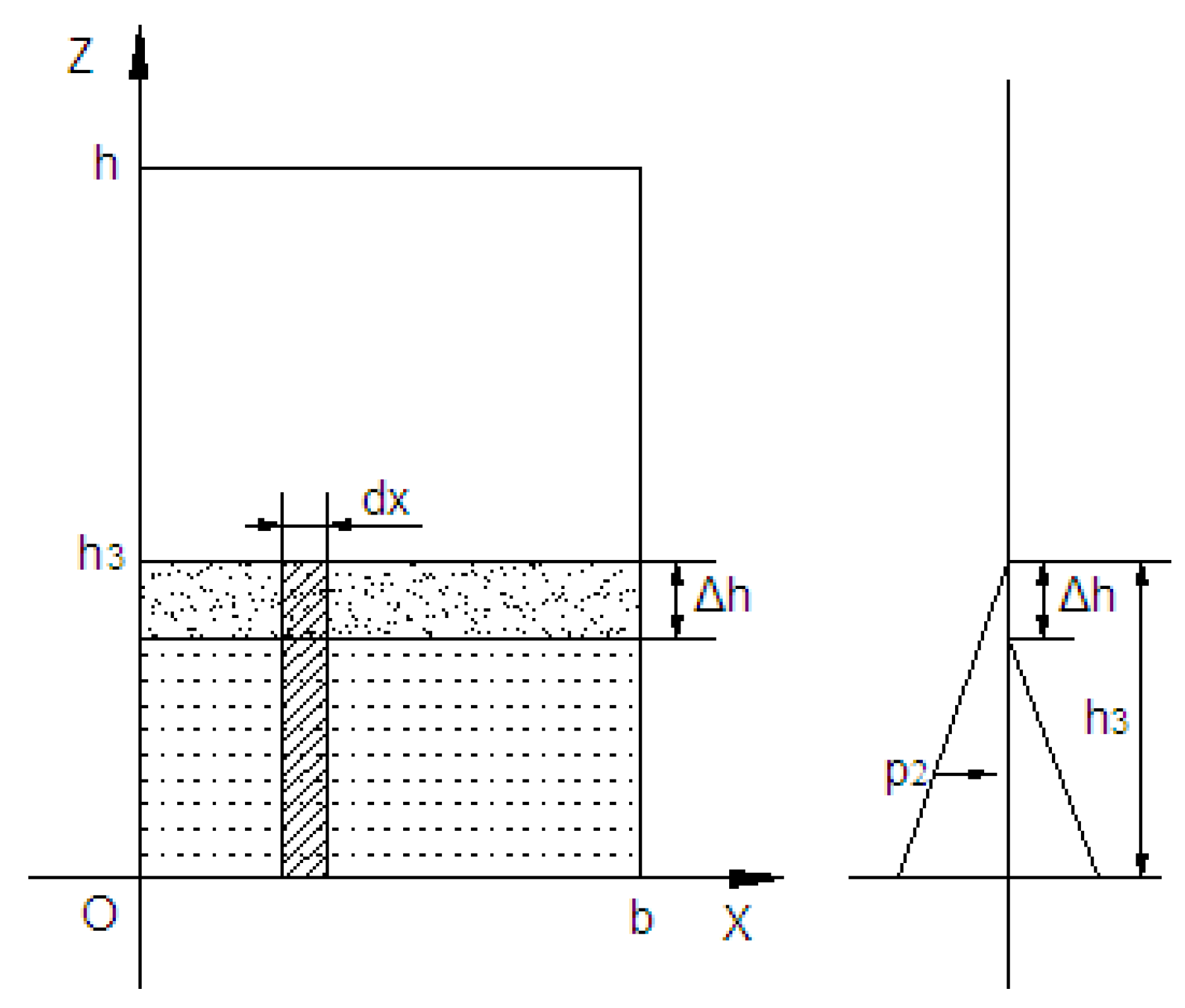
Figure 3.
Schematic diagram of the herringbone gate subjected to wind pressure.
Figure 3.
Schematic diagram of the herringbone gate subjected to wind pressure.
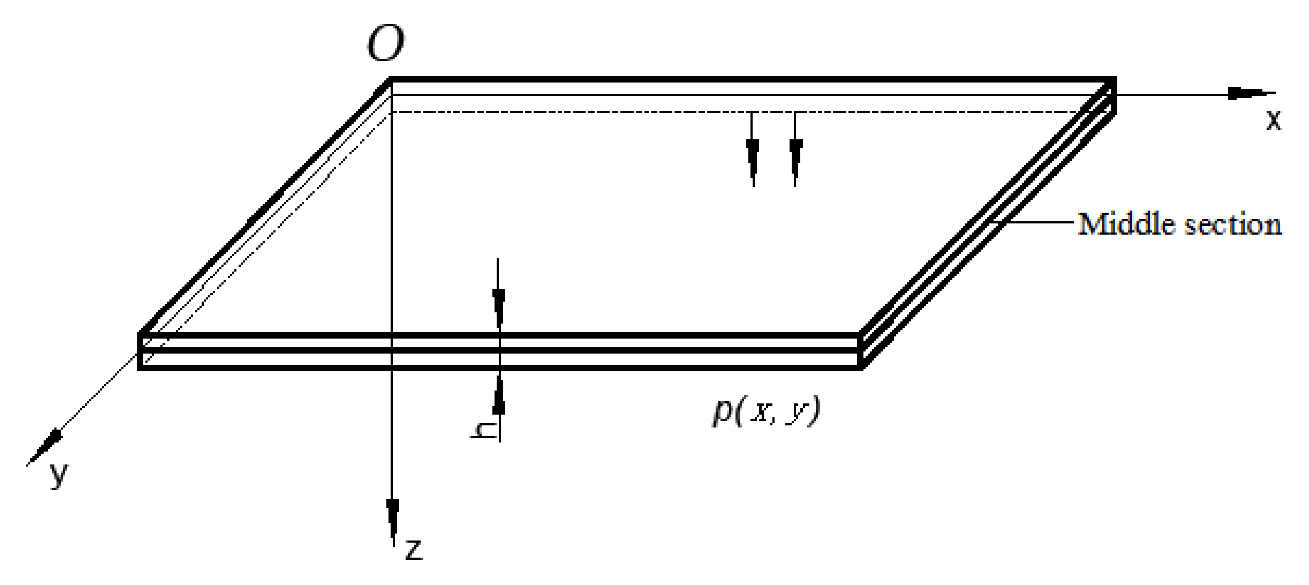
Figure 4.
Middle section of a thin plate in a rectangular coordinate system.
Figure 4.
Middle section of a thin plate in a rectangular coordinate system.
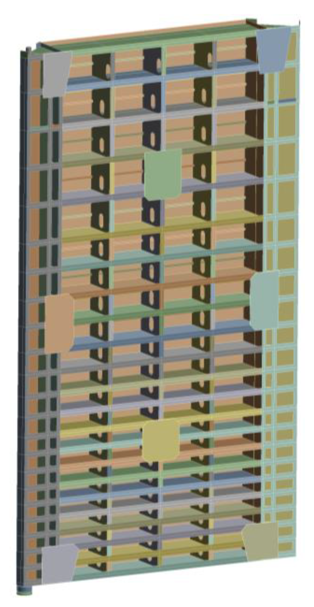
Figure 5.
Three-dimensional solid model of gate Pro E.
Figure 5.
Three-dimensional solid model of gate Pro E.
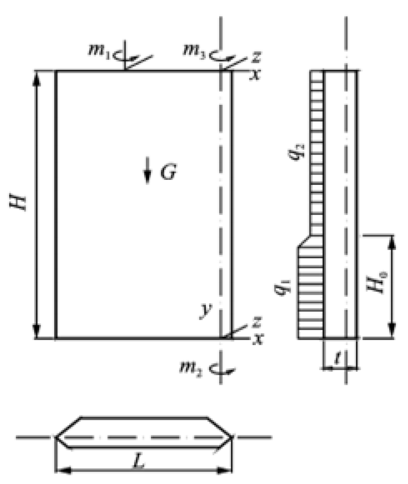
Figure 6.
Schematic diagram of the force under the operation of the herringbone door.
Figure 6.
Schematic diagram of the force under the operation of the herringbone door.
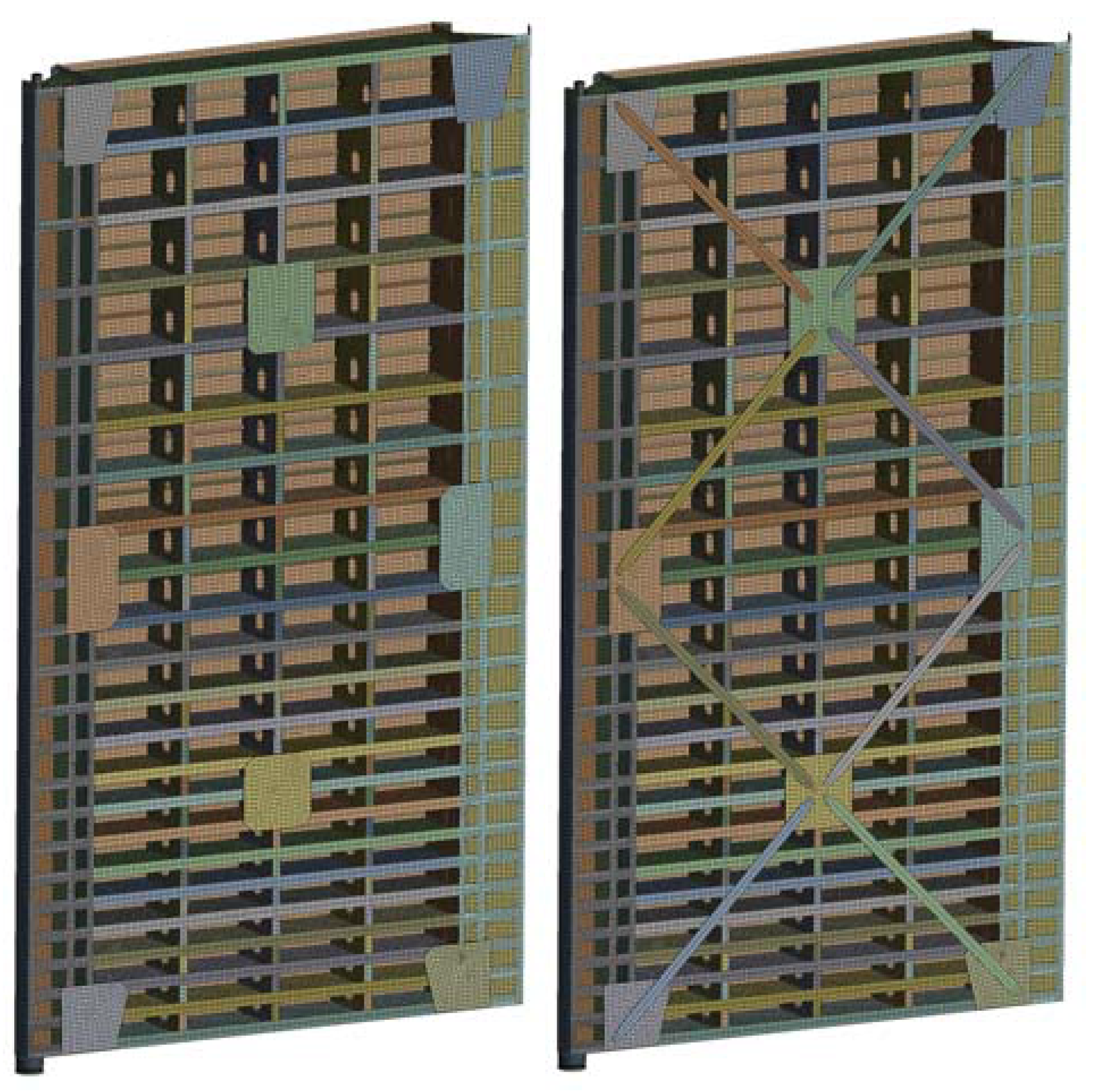
Figure 7.
Finite element model of gate without and with back tie rods.
Figure 7.
Finite element model of gate without and with back tie rods.
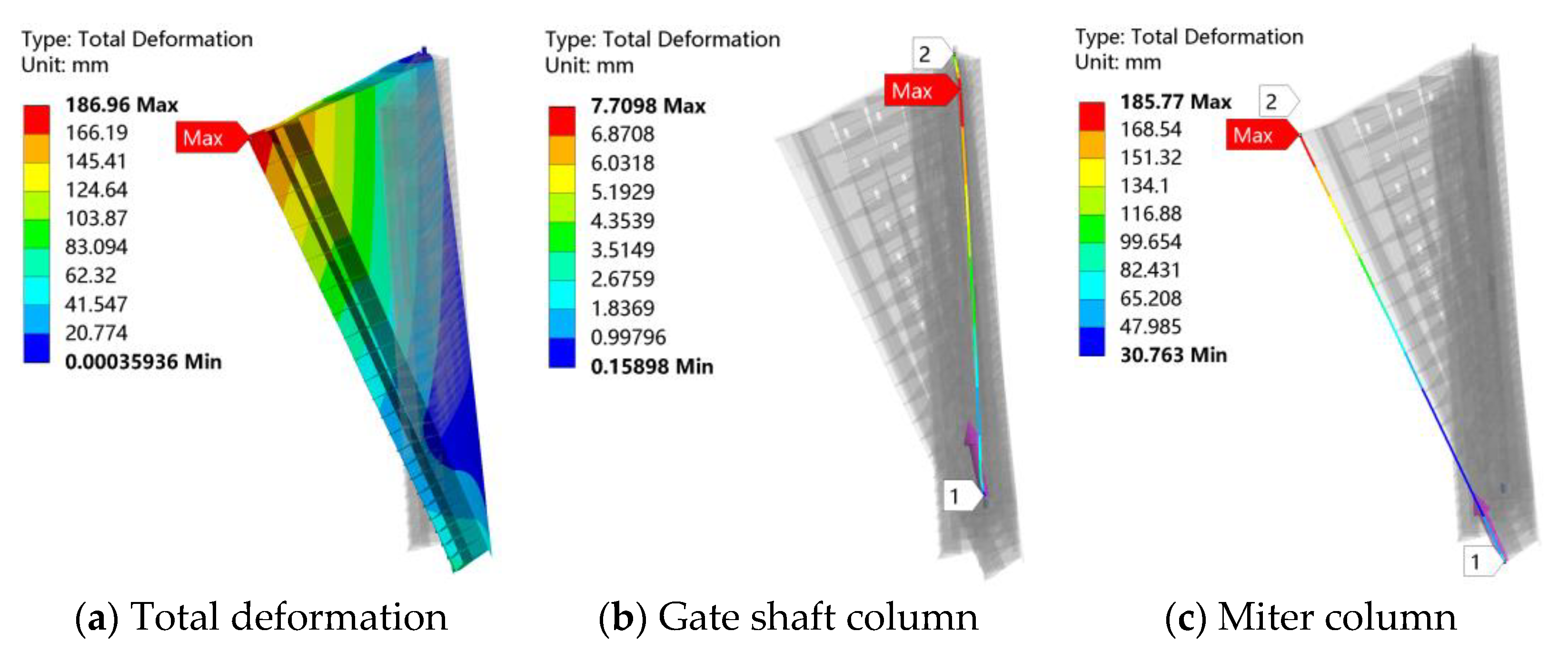
Figure 8.
(a) Deformation of the overall gate, (b) Deformation of the gate shaft column, and (c) Deformation of the miter column without the back tie rod under self-weight.
Figure 8.
(a) Deformation of the overall gate, (b) Deformation of the gate shaft column, and (c) Deformation of the miter column without the back tie rod under self-weight.
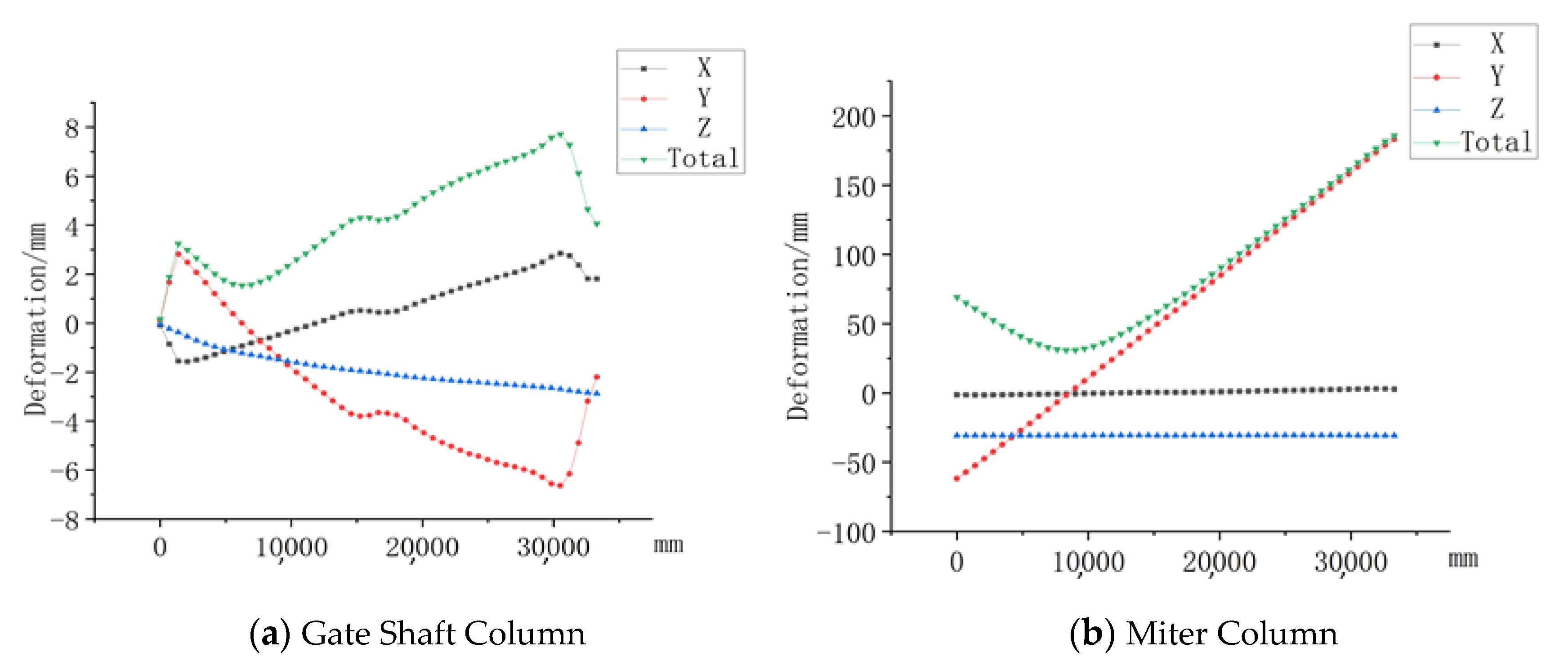
Figure 9.
(a) Deformation of the gate shaft column, (b) Deformation of the miter column without the back tie rod at different directions under self-weight.
Figure 9.
(a) Deformation of the gate shaft column, (b) Deformation of the miter column without the back tie rod at different directions under self-weight.
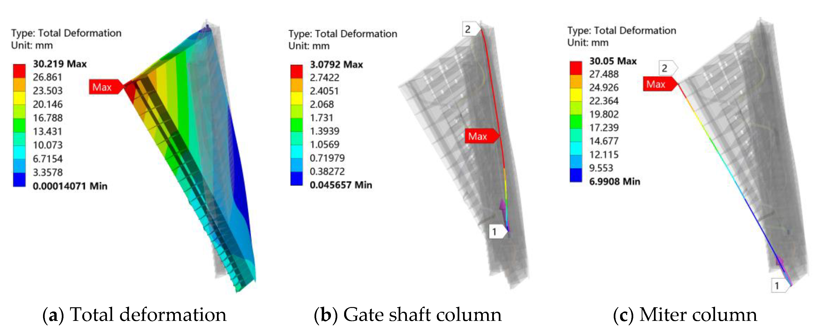
Figure 10.
(a) Deformation of the overall gate, (b) Deformation of the gate shaft column, and (c) Deformation of the miter column with the back tie rod under self-weight.
Figure 10.
(a) Deformation of the overall gate, (b) Deformation of the gate shaft column, and (c) Deformation of the miter column with the back tie rod under self-weight.
Figure 11.
(a) Deformation of the overall body, (b) Deformation of the door shaft column of the backless tie rod gate in a static state.
Figure 11.
(a) Deformation of the overall body, (b) Deformation of the door shaft column of the backless tie rod gate in a static state.
Figure 12.
Deformation of the shaft column of the backless tie rod gate in the static state in different directions.
Figure 12.
Deformation of the shaft column of the backless tie rod gate in the static state in different directions.
Figure 13.
(a) Deformation of the gate body, (b) Deformation of the shaft column of the gate with a back tie rod in a static state.
Figure 13.
(a) Deformation of the gate body, (b) Deformation of the shaft column of the gate with a back tie rod in a static state.
Figure 14.
(a) Deformation of the overall structure of the backless tie rod gate, (b) Deformation of the door shaft column, and (c) Deformation of the miter column under the door-opening condition.
Figure 14.
(a) Deformation of the overall structure of the backless tie rod gate, (b) Deformation of the door shaft column, and (c) Deformation of the miter column under the door-opening condition.
Figure 15.
(a) Deformation in different directions of the shaft column, (b) Deformation of the mitered column of the gate without the back tie rod under the door-opening condition.
Figure 15.
(a) Deformation in different directions of the shaft column, (b) Deformation of the mitered column of the gate without the back tie rod under the door-opening condition.
Figure 16.
(a) Deformation of the overall gate, (b) Deformation of the door shaft column, and (c) Deformation of the miter column under the door-opening condition.
Figure 16.
(a) Deformation of the overall gate, (b) Deformation of the door shaft column, and (c) Deformation of the miter column under the door-opening condition.
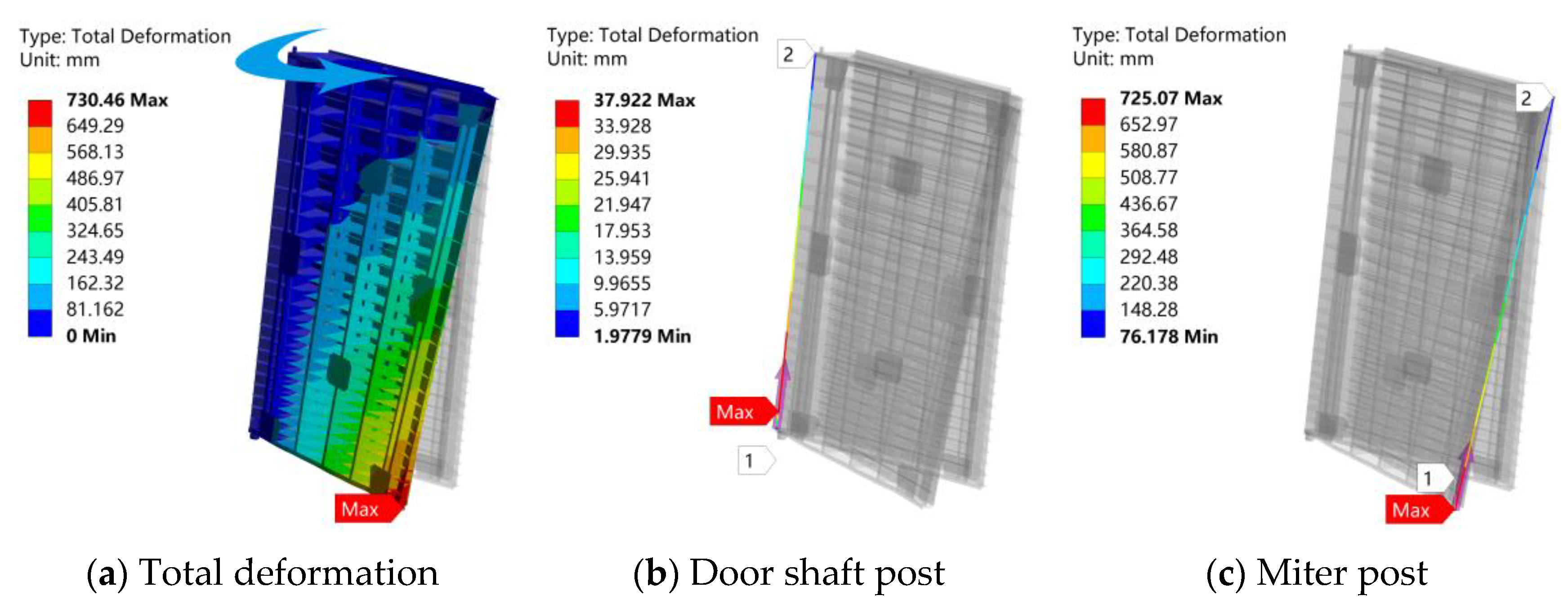
Figure 17.
(a) Deformation of the overall structure of the backless tie rod gate, (b) Deformation of the door shaft column, and (c) Deformation of the miter column under the door-closing condition.
Figure 17.
(a) Deformation of the overall structure of the backless tie rod gate, (b) Deformation of the door shaft column, and (c) Deformation of the miter column under the door-closing condition.
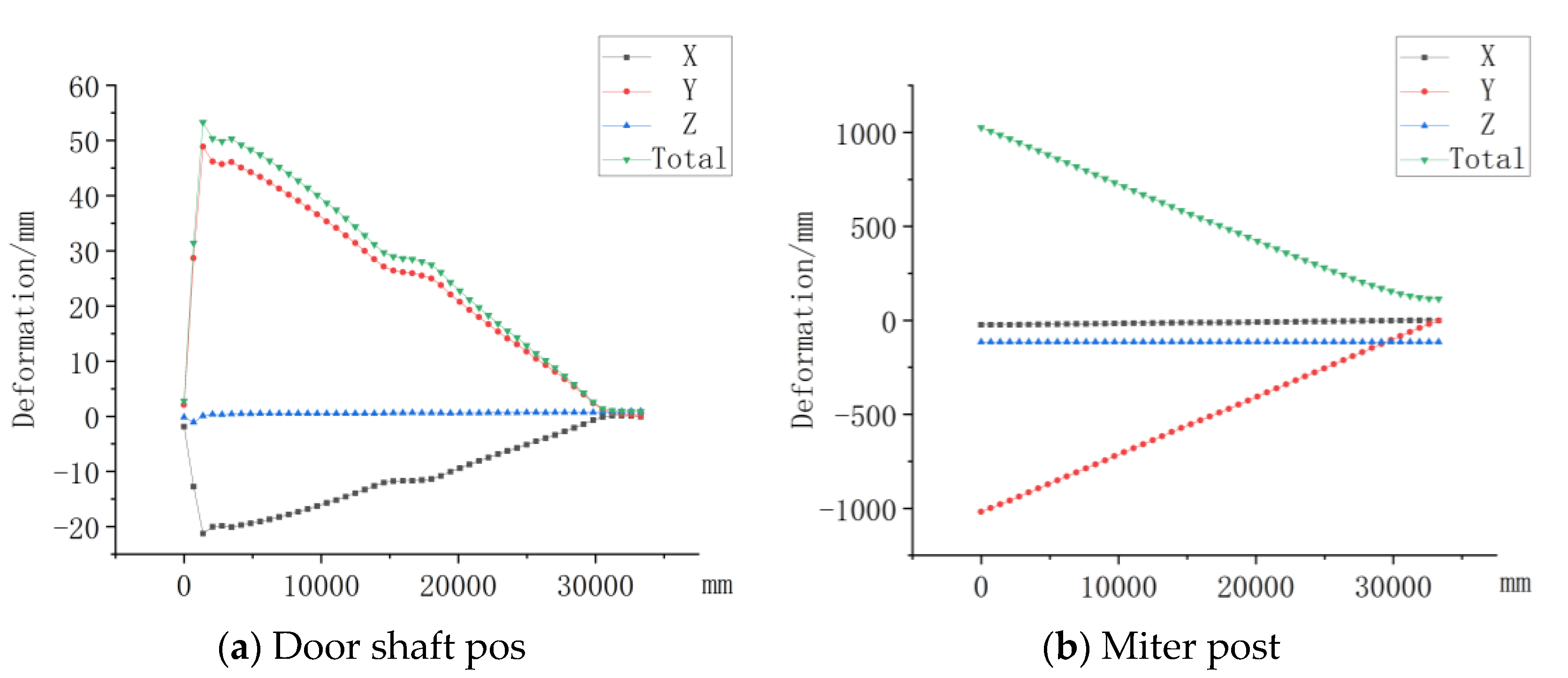
Figure 18.
(a) Deformation in different directions of the shaft column, (b) Deformation of the miter column of the gate without the back tie rod under the door-closing condition.
Figure 18.
(a) Deformation in different directions of the shaft column, (b) Deformation of the miter column of the gate without the back tie rod under the door-closing condition.
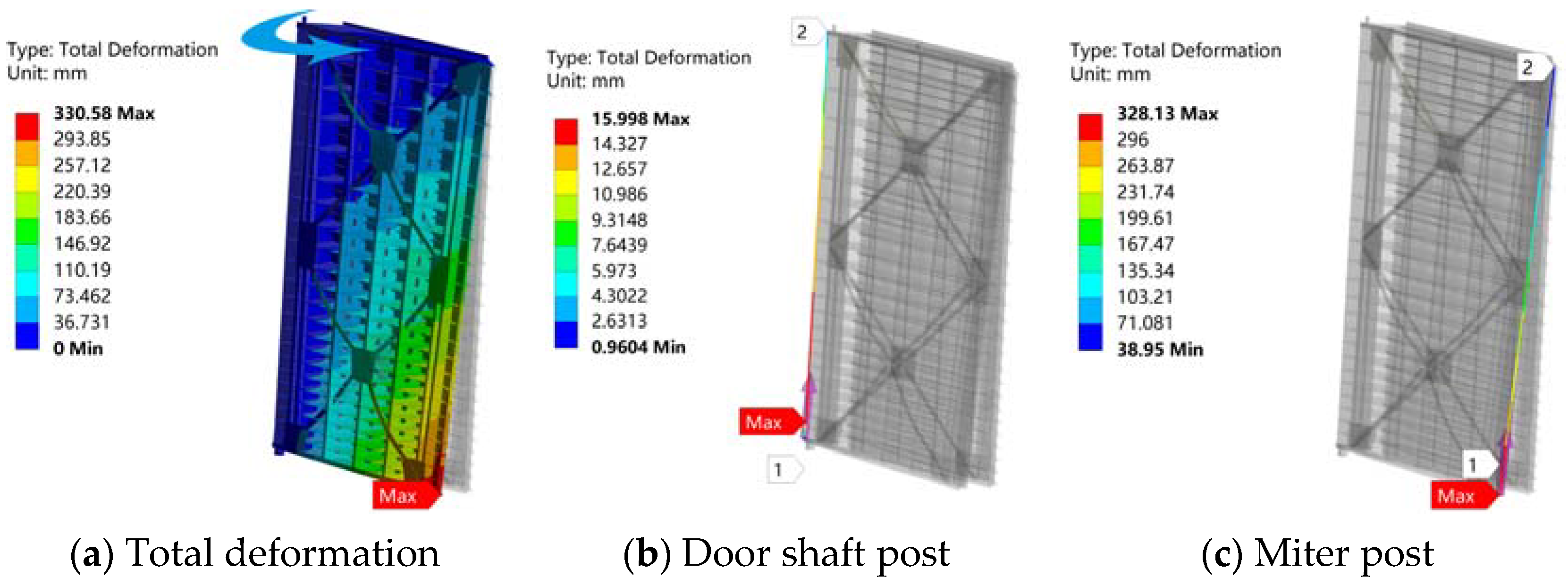
Figure 19.
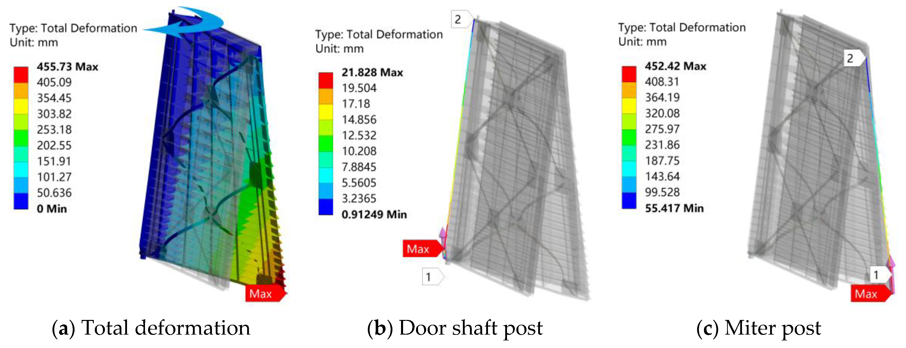
(a) Deformation of the overall gate, (b) Deformation of the door shaft column, and (c) Deformation of the mitered column under the door-closing condition.
Figure 19.
(a) Deformation of the overall gate, (b) Deformation of the door shaft column, and (c) Deformation of the mitered column under the door-closing condition.
Table 1.
Wind pressure height variation factor.
Table 1.
Wind pressure height variation factor.
| Height above Ground (m) | 10 | 15 | 20 | 30 |
|---|
| 1 | 1.15 | 1.25 | 1.42 |
Table 2.
Stress load and constraint of the gate under different states.
Table 2.
Stress load and constraint of the gate under different states.
| State | Gravity | Wind Load | The Minimum Water Pressure in Upper Reaches | Water Pressure in Lower Reaches | The Maximum Water Pressure in Upper Reaches | Bottom Pivot Constraint | Top Pivot Constraint | Miter Column Constraint | Push–Pull Rod Restraint |
|---|
| 1 | ✔ | | | | | ✔ | ✔ | | |
| 2 | ✔ | ✔ | | ✔ | ✔ | ✔ | ✔ | ✔ | |
| 3 | ✔ | ✔ | ✔ | | | ✔ | ✔ | | ✔ |
| 4 | ✔ | ✔ | | ✔ | | ✔ | ✔ | | ✔ |
Table 3.
The maximum deformation of the gate with or without the back tie rod under no external force and self-weight mm.
Table 3.
The maximum deformation of the gate with or without the back tie rod under no external force and self-weight mm.
| The Setting of Back Tie Rod | Total Deformation of Gate | Gate Shaft Column | Miter Column |
|---|
| X | Y | Z | Total Deformation | X | Y | Z | Total Deformation |
|---|
| No back tie rod | 186.96 | 2.8475 | −6.639 | −2.881 | 7.7098 | 2.9945 | 183.19 | −30.752 | 185.77 |
| Back tie rod | 30.219 | −0.549 | −2.333 | −2.825 | 3.0792 | −0.501 | 29.231 | −6.9884 | 30.05 |
Table 4.
The maximum deformation of the gate with or without the back rod in the static state mm.
Table 4.
The maximum deformation of the gate with or without the back rod in the static state mm.
| Back Tie Rod Setting Situation | Total Gate Deformation | Door Shaft Post |
|---|
| X Direction | Y Direction | Z Direction | Total Deformation |
|---|
| Backless tie rod | 276.3 | −13.533 | 275.21 | 43.005 | 275.81 |
| With back rod | 266.71 | −12.431 | 265.7 | 40.136 | 266.23 |
Table 5.
Maximum deformation of the gate with and without a back tie rod in a state of 3 mm.
Table 5.
Maximum deformation of the gate with and without a back tie rod in a state of 3 mm.
| Back Tie Rod Setting Situation | Total Gate Deformation | Door Shaft Post | Miter Post |
|---|
| X Direction | Y Direction | Z Direction | Total Deformation | X Direction | Y Direction | Z Direction | Total Deformation |
|---|
| Backless tie rod | 730.46 | 14.704 | −34.949 | −5.1192 | 37.922 | 16.635 | 720.89 | 76.159 | 725.07 |
| With back rod | 330.58 | 6.3417 | −14.677 | −3.7689 | 15.998 | 6.4437 | 326.8 | 29.318 | 328.13 |
Table 6.
The maximum deformation of the gate with and without back lever in the closed state mm.
Table 6.
The maximum deformation of the gate with and without back lever in the closed state mm.
| Back Tie Rod Setting Situation | Total Gate Deformation | Door Shaft Post | Miter Post |
|---|
| X Direction | Y Direction | Z Direction | Total Deformation | X Direction | Y Direction | Z Direction | Total Deformation |
|---|
| Backless tie rod | 1032.9 | −21.248 | 48.881 | −1.0649 | 53.3 | −23.458 | −1018.8 | −114.52 | 1025.4 |
| With back rod | 455.73 | −9.2346 | 19.779 | −1.26 | 21.828 | −9.1849 | −449.96 | −46.911 | 452.42 |


