Article

Alternative Solutions for Small Hydropower Plants

1
Department of Electrical Engineering, Cracow University of Technology, Warszawska 24 St., 31-155 Cracow, Poland
2
Institute of Fluid-Flow Machinery of the Polish Academy of Science, Fiszera 14 St., 80-231 Gdansk, Poland
3
AQUA-Tech, Lipcowa 64 St., 32-540 Trzebinia, Poland
4
WODEL, Piłsudskiego 40 St., 67-100 Nowa Sol, Poland
*
Author to whom correspondence should be addressed.
Energies 2022, 15(4), 1275; https://doi.org/10.3390/en15041275
Submission received: 22 December 2021 / Revised: 27 January 2022 / Accepted: 7 February 2022 / Published: 10 February 2022
(This article belongs to the Special Issue Energy Conversion System – Small Hydropower Plants)

Abstract

:
Obtaining energy from renewable resources is a worldwide trend in the age of increasing energy demand. Hydropower has some potential in this field, especially for low-power locations. However, construction of such facilities requires high expenses, which is why some attempts at lowering the costs have been made, i.e., by proposing alternative solutions to the classic ones. This paper proposes a selection of options for small hydropower plants (SHP) that lower the investment costs while keeping up profitable operations. The proposed solutions concern simplifying the turbine’s and generator’s integration by installing them in dedicated prefabricated concrete modules. A rare but simple and cheap semi-Kaplan type of turbine with a non-classical spiral inflow is proposed. The turbine operates a permanent magnet (PM)-excited generator, converting the energy at a variable rotational speed. Thanks to this approach, it is possible to simplify the regulation system and eliminate expensive mechanical transmission. However, on the power grid side, a power electronic converter (PEC) must be coupled with the generator. The advantage of this solution compared to the classical ones is that the reliability of power electronics is much higher than that of mechanical systems. This paper presents modeling research on semi-Kaplan turbines’ series development, and a dedicated PM generator is presented as an example of a complete hydro unit with 50 kW power.

1. Introduction

The hydropower potential of medium- and high-water damming is already used in most countries. Yet, hydropower potential that is so far unused in Poland, among others, concerns the heads on which small hydropower plants (SHPs) can be built. Looking ahead, for rational and economically profitable use of unused water damming, it is necessary to develop cheap applications, which can be used in SHPs [1,2,3].
The idea of integrating an electric generator and turbine as a cheap application for SHP appeared in recent years. In the literature, there are many conceptual applications for this. For instance, a compact structure for the machine can be achieved by placing the generator in hermetic housing axial to the turbine [4]. These solutions are based, in most cases, on cage-induction generators, where the rotational speed is high and for low and ultra-low heads it is necessary to use a speed-increasing gear. Placing the oil-lubricated gear inside the casing risks oil leakage and river pollution. Such a design of low-head low-power hydro units is not effective due to the limitation of the flow cross-section area and significant water-flow turbulences in the hydraulic channels of the machine. Another solution, which eliminates the machine’s smaller hydraulic cross-section issue, is to place the turbine inside the rotor of the electric generator. A synchronous generator with permanent magnets is used for transmission elimination and increased efficiency across a wide range of loads. First, such topologies appeared in the 1940s [5,6]. Those were low-power units (<1 MW) that faced issues related to tightness between the stator and rotor. High-power units also appeared at the time, such as a power plant on the river Rhein (Laufenburg, Germany) [7]. In the 1980s, elastic tightening dedicated to turbines with adjustable turbine blades was developed. This solution was implemented in HPP Weinzödl (Austria, on the Mur river) in 1982, made up of two parallel STRAFLO turbines of 3.7 m diameter and with an overall power of 8 MW [8]. Another solution, named StrafloMatrix, implemented by Austrian company VA TECH HYDRO GmbH, was dedicated to small hydropower plants. Two units (300 kW and 700 kW) were manufactured and installed in the Agonitz hydropower plant on the Steyr river in Austria [9,10]. A similar design dedicated to small hydropower plants was assembled in the AKWA power plant on the Biała Głuchołaska river near Nysa (Poland) [11]. There were two parallel hydro units with 150 kW overall power. The energy conversion system was also based on a turbine and a PM synchronous generator. In this design, a variable rotational speed achieved by using a power electronics converter replaced turbine runner blade regulation. This topology was carefully examined and analyzed by the authors [11,12,13]. All the solutions described above refer to assembling a hydraulic turbine inside a synchronous generator, which is called “full integration.” Significant advantages of the full integration of the turbine inside the electric generator’s rotor are the size adjustment of the hydro unit compared to the pipe segment and also the lack of a drive shaft and gears, meaning a turbine set can be placed directly in the pipe. Another significant advantage of such a design is the electric-generator cooling by the water flowing inside its housing, which efficiently prevents long-term generator overload.
The main disadvantages of full integration are physical phenomena related to the gap between the rotor and stator of the electric generator (in a hydraulic turbine, permanent magnets are attached to the outer runner ring). There are two possible solutions: wet and dry gaps. A wet gap is filled with water during normal operation and does not require special sealing. However, it is necessary to seal the surface of the rotor with permanent magnets and the stator windings, too. One of the major drawbacks of such a solution is significant power loss in the gap (caused by water friction on the surfaces of the stator and rotor), flow turbulence and transport of small polluting particles. Initial power loss estimations based on measurements of existing hydro units were as high as 10% of the hydro units’ nominal power depending on the gap size and rotational speed of the turbine. Another drawback of a wet gap, besides the power losses, is fast exploitation of the rotor and stator tightening when operating with polluted water, i.e., with sand. Object wear [11] has proven the necessity of tightening materials’ exchange at least once per year. Another drawback to this kind of solution is the gradual dampness of the generator’s stator winding, which causes the insulation to deteriorate, resulting in discharge and short-circuits of the stator winding. Moreover, integrating a turbine of specified dimensions in a synchronous generator’s rotor requires the generator to be designed accordingly. This increases the costs of hydro-unit manufacturing and makes it impossible to create a type-series of the machines. A dry gap, on the other hand, occurs when during normal operation, a small amount of water does not cause significant power loss. This solution is implemented using a special flexible tightening system. The solution has been extensively researched by the Institute for Hydraulic Fluid Machinery at Graz University of Technology, and was described in [8], which tested a turbine with a runner diameter of 400 mm at a rotational speed of 1500 rpm. Multivariant tests were carried out to analyze the strengths of various sealing materials in different levels of water pollution, as well as the power losses and amount of water leaking. The obtained power losses were at 2% and the water leakage was 0.04 L/s during the sealing tests for pure water. In the case of water contaminated with sand, the power losses and water leakage through the seal almost doubled. Studies conducted over a long period have shown significant damage to sealing materials [8]. To reduce the wear on the sealing, a system of cleaning it with pressurized water using a dedicated lubricant was proposed. The proposed solution fulfilled its task; however, it was technically complicated.
When summarizing the considerations for how to integrate a complete turbine and an electric generator, the wet gap is simpler and cheaper to implement in practice, but it is generally expensive in operation (requiring frequent replacement of the stator winding insulation) and causes significant power losses. The dry gap, on the other hand, is technically complicated and requires additional cleaning systems. This solution is expensive to implement, is dedicated to high-power hydro units and thus has not been adopted by SHP. The authors of the paper have been dealing with alternative solutions for low-head SHP for almost 15 years and have recently attempted to modify the so-called hydro unit integration. This solution assumes the use of independent elements of the hydro unit (turbine and generator excited by permanent magnets without a mechanical transmission), and the integration itself is about placing them in one prefabricated concrete block and providing insulation from water with effective heat dissipation at the same time. The main improvement—in addition to the simplicity and durability of the offered solution—is its relatively low price compared to classic solutions. To that end, the authors of the paper propose a solution based on technology to unify and prefabricate the damming weir, power-plant tunnels, and fish passes, and to equip the power plant with unified hydro sets dedicated to working at variable rotational speeds. The proposed unification and development of type-series for hydraulic turbines will allow for multiple installations of the same modules and hydro sets in one facility. The decision to use a variable rotational speed for turbines and a permanent magnet-excited generator results from the need to simplify the turbine design and eliminate mechanical transmission [14,15,16,17,18,19,20,21,22]. Solutions for electric power-generation systems with variable rotational speeds are commonly used in producing wind energy, mainly with higher powers above 1 MW. For the hydropower sector, these are new solutions, although they are already partially in use [14]. In the case of a permanent magnet-excited generator, it is necessary to use an additional power electronic converter that adjusts the parameters of the generated electric power to the requirements of the power grid [16,17,18]. The operation of the turbine at variable rotational speeds gives the possibility of simplifying the structure by eliminating blade-regulation systems or using only singular regulation (stationary guide wheel blades or stationary turbine runner blades). In this case, the power electronic converter is responsible for the main bulk of control. The above-mentioned requirements are met by turbines of the following designs: runner (with fixed blades) and a semi-Kaplan turbine with non-classical spiral inflow [15]. The design of the flow system of these turbines—related to the relatively small dimensions of the turbines [15,16]—might satisfy the need to develop an advantageous combination of a relatively high level of efficiency and a high speed, which significantly reduces the cost of producing a hydro set. Regarding the flow rate, these solutions allow for effective use of the hydropower potential for damming structures with small and medium heads, in the range of 1 to 10 m of the water column.
Designing a turbine with a high specific speed is quite a difficult task, and designing a turbine with a high specific speed and relatively high efficiency (above 87% on a laboratory scale, and above 90% on an industrial scale) is greatly difficult, requiring a lot of experience and knowledge. This is related to the shaping of the blades with kinematic parameters that ensure a high flow rate of the blade system. This task is difficult because increasing the speed comes at the expense of efficiency, which decreases due to the increased flows and hence increased hydraulic losses. It should also be considered that in turbines with a high specific speed, it is easier to experience the phenomenon of cavitation and the related cavitation erosion, which in turn, may limit the service life of these machines.
This paper attempts to present work that is contributing to the development of unified solutions regarding design technologies, as well as turbines and generators. As the turbine of choice, the semi-Kaplan model with a non-classical spiral inflow on the runner blades was selected (the turbine does not have classic guide vanes that guide water onto the runner, and the tangential component of the velocity before the runner is generated by a specially shaped spiral water inlet system) as a rational case in terms of its application in SHP, due to its relatively simple and cheap design.
In short, as a novelty for SHP, we consider the semi-Kaplan turbine operating at variable rotational speeds. This is especially important in low-head hydropower plant applications as big changes of conditions are often encountered, meaning special flexible solutions are required. Additionally, we propose considering the small hydropower plant as an assembly of prefabricated modular parts (turbine sets). In this sense, relevant parts of the hydropower plant can easily be replaced by other adequate parts suited to the conditions (the head and flow rate) of a small power plant. Such low-head solutions can supply energy to the national power grid and separate grids for rural communities located far from urbanized cities (vide Africa, Asia, South America). The proposed solutions can easily be adapted locally for small rivers with a low head potential.
Based on the results of modeling tests, a series of prototype turbines were developed for various characteristic runner diameters ranging from 0.5 to 1.6 m and several values of water heads. The work presented in the paper is complemented by a permanent magnet-excited generator designed for a selected exemplary hydro unit, intended to cooperate with a power electronic converter system. Section 1 of the article introduces the subject of alternative solutions to SHP and describes the state of knowledge in this field. Section 2 presents alternative construction technologies that can be used in SHP. Section 3 deals with the entire energy conversion system for SHP. Section 4 discusses the presented results, while Section 5 offers concluding remarks and recommendations.

2. Prefabrication and Modular Unification of Building Technologies for Small-Scale Hydropower

In recent years, it has become a popular solution to equip weir installations with movable composite closures, known as sheath (or water bag) closures. Their operation does not cause water blockages during high and flood flows. These solutions are perfect for low flows, creating channel retention. Weir shells are most often filled with water drawn from a river; thus, they constitute a solution with high ecological safety. Shell closures have many operational advantages, especially in winter, as the ice floe and current ice do not freeze to the elastomeric weir coating, making them a popular solution for dams up to 5 m high. Technological development of shell weirs has led composite movable flap weirs to be introduced with a pneumatic or hydraulic-type shell actuator (filled with water). This solution is especially recommended for dams with a height of 0.5 to 1.5 m. The working medium of such damming is a pneumatic shell actuator. The dampers are made of carbon or high-density polyethylene composites. Eliminating steel elements from these solutions significantly improves their operational safety in winter conditions. In addition, elements made of composites do not react with water or require maintenance or lubrication, and thus they are ecologically clean solutions. The above solutions are fixed to the reinforced concrete bottom structure, as well as to pillars and bank abutments. The main task of the proposed technology is to shorten the construction time in the riverbed and improve the quality of block elements by making these from precast concrete with composite reinforcement. To eliminate quality problems and shorten the construction time of small energy facilities, we propose unifying the series of prefabricated reinforced concrete elements. These are elements (Figure 1) of dams with shell closures, elements of waterpower plants, and fish passes.
Based on technical documentation for the facility, after making design calculations for the prefabrication plant, production and assembly guidelines for the module were developed (Figure 2), which include, inter alia, the:
  • external dimensions of individual prefabricated elements;
  • arrangement of reinforcement;
  • number, position and dimensions of holes;
  • installation layout;
  • anchoring elements;
  • plan and order for placing individual elements;
  • corner and additional reinforcements;
  • means of support;
  • locations and methods of protection against moisture or water;
  • assembly of foundation and additional concretes.
When we know what stakeholders strive to build, the appropriate technology can be adapted to it. For large hydrotechnical modules, creating so-called composite walls or ceilings is appropriate. This is a kind of semi-finished product with filigree walls, thanks to which there is no need for formwork or reinforcement at the construction site. The wall element created in this way, made of two reinforced concrete slabs, constitutes a “lost formwork”—a form filled with reinforcement, which when concrete is poured in and dries, forms a durable structural core. Generally, the idea is to create a network of monolithic structures on the construction site, which are durable as a whole, even though they consist of several elements, by appropriately using and joining together prefabricated elements. The appropriate weight of the object, which is of great importance in hydro-engineering at the construction site due to the stability of the structure, is obtained by filling the voids and prefabricated boxes with concrete or filling a stone riprap with poured concrete. In the elements delivered to the site, the whole reinforcement is installed, thus satisfying the basic load-bearing capacity requirements, along with fittings for closures, gratings, and sensor and measuring apparatus drifts, as well as the necessary control wiring or cable glands. By opting for prefabricated elements, it is possible to build durably but also much faster and more conveniently than with traditional solutions. The cost of building the structure using the prefabricated composite elements is 20–30% lower than for the same buildings made using traditional techniques.

3. Turbine Set Module with an Electric Energy Generation System

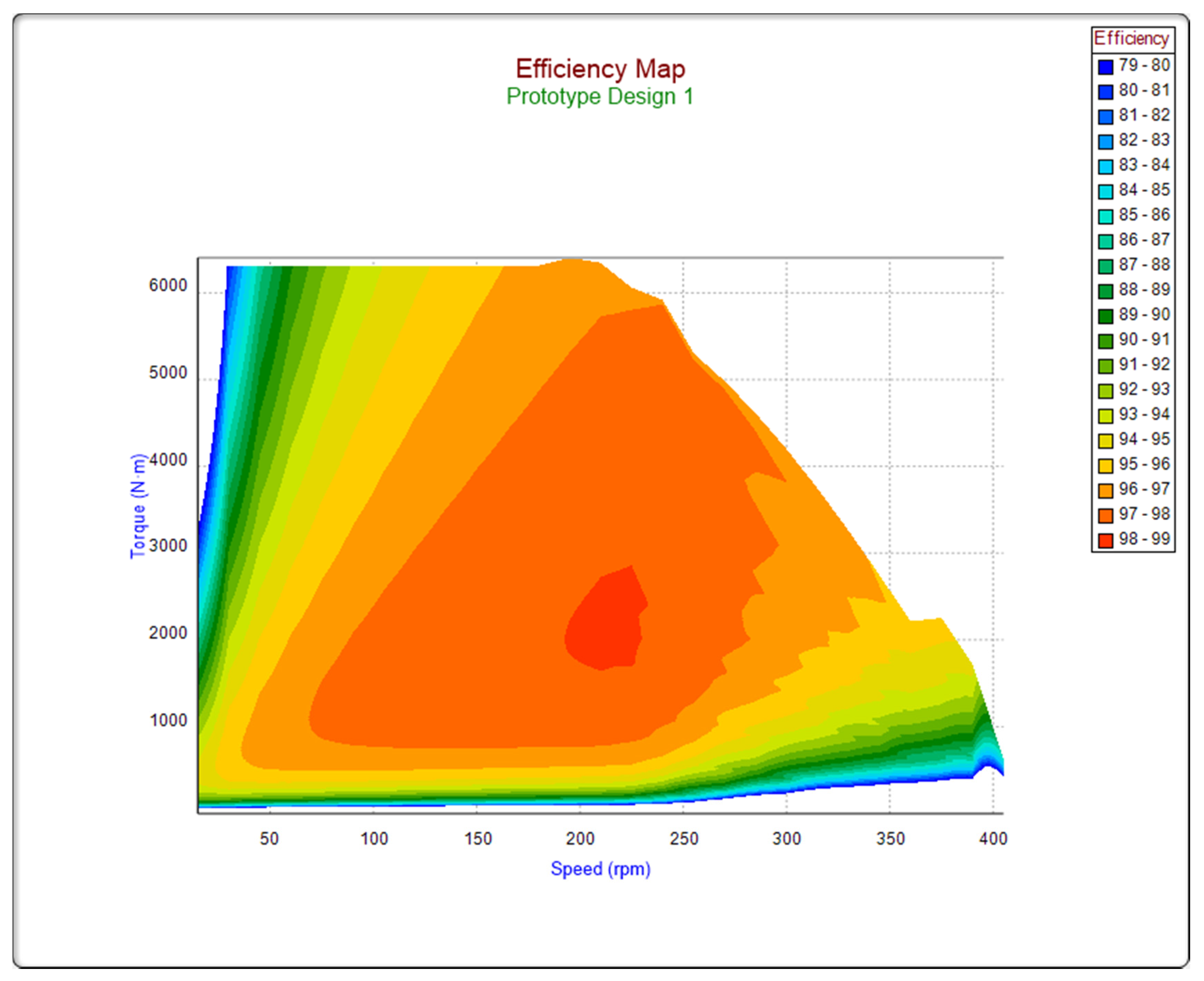
3.1. Energy Conversion Efficiency

In hydropower plants with the lowest heads, with classic current-generation systems based on a cage generator that operates at a constant rotational speed, a significant problem is the variability of the head. Even a slight change in the head, e.g., by 20%, can cause a loss of efficiency, which for high-efficiency Kaplan turbines, can reach up to 5% [18,23,24]. A significant disadvantage of using cage generators is the need to use mechanical transmissions that cause excessive noise, reduce efficiency—i.e., via energy generation—and increase the operating costs of the power plant. Another problem is the need to compensate for reactive power. It should also be noted that IE3-class squirrel-cage generators, which provide a relatively high rate of efficiency (e.g., for power between 45 and 110 kW, the efficiency is between 94 and 95.5%), are characterized by a significant loss of efficiency for lower powers. As is commonly known, SHPs (especially run-of-river ones) experience large changes of generated power depending on the hydrological conditions. Therefore, the amount of electric power generated during the year depends on the efficiency of the generator for different power values. The above disadvantages of classic electric power-generation systems can be eliminated by using a synchronous generator with permanent magnets and a power electronic converter (PEC). These solutions, commonly used in wind energy, can significantly increase the electric power production in SHP, especially for low heads. Hence, the authors prefer an electric power-generation system consisting of a highly efficient synchronous generator with permanent magnets and a dedicated inverter. The advantage of the proposed solution over the classic one is shown, for instance, in [14]. As an example, comparing a cage generator operating with a mechanical belt transmission to a synchronous generator (with permanent magnets) coupled with an inverter, the difference in efficiency between these two solutions ranges from 2% for operation at powers close to the rated values to 8% for lower generator powers. So, we can conclude that the profit of production will be visible mainly at low SHP flows. By determining the annual course of the river flow value and the universal characteristics of the turbines, it is possible to estimate the production difference when using these two analyzed generators. In the case of Kaplan turbines, the efficiency gain will be 2–5%, while for propeller turbines, it may even reach 5–20% [18,23,24]. Using a permanent magnet-excited synchronous machine as an electric power generator has significant advantages, which are primarily: the high efficiency of energy conversion in a wide load range, no mechanical transmission and high reliability [14]. Using such a generator for power system applications, however, has some disadvantages, as it requires the use of a power electronic converter to transform the electric power from the generator to meet the requirements of the power grid (Figure 3). Though it is an extra effort to introduce it, when you have added such an energy conversion system, however, this enables precise control of the active and reactive power.
Another advantage of this solution is the ability of the generator to operate at any rotational speed (limited to a certain extent by the parameters of the converter). This is important when matching the speed of the hydraulic turbine to the selected power plant. The properties of the hydraulic turbine are greatly influenced by the design of the inlet and outlet channels, as well as the location of other turbines operating in parallel in the same power plant, which may cause flow turbulence during operation. The ability to adjust the rotational speed to a given situation may increase the efficiency of the hydro unit, along with the capacity to change the rotational speed online during the operation of the hydro unit. Operating with variable rotational speeds allows high efficiency of energy conversion to be maintained for different values of the turbine’s flow rate [25,26,27,28,29,30] through a simplified mechanical structure of hydraulic turbines, such as the proposed solution of the semi-Kaplan turbine. The power electronic converter [31,32,33,34] makes it possible to adjust the parameters of the electric power generated by the generator to the parameters defined by the power system (e.g., voltage 400 V, 50 Hz) and control the power flow to the grid. The power electronic system takes over the role of a classic mechanical control system, e.g., setting the angle of the blades, which ensures a constant speed of the generator in classic solutions. This is a very significant advantage of the proposed solution because the reliability of power electronics systems is much greater than the reliability of the mechanical control system that sets the blade angle, and the operating costs are much lower. The hydroelectric turbine is designed based on individual adjustments to match the conditions of the hydrological potential of the river. The main element, which controls the water flow, is the head regulation system H, controlled to ensure the appropriate water level in the upper tank. The turbine’s power control mainly depends on the current hydrological possibilities [25,26,27,28,29,30], that is, the current value of the flow rate Q. The main elements of the SHP energy conversion system, working with a variable rotational speed, are presented in Figure 4.

3.2. Semi-Kaplan Turbine

The semi-Kaplan turbine is a relatively simple structure without a classic guide vane system. In this turbine, the tangential component of flow velocity is generated in front of the runner through a specially shaped sheet structure in a spiral form—the so-called helices. It should be emphasized that this is not a classic spiral system that can be found in other classic Francis and Kaplan turbines (Figure 5).
From the design point of view, the lack of guide vanes and their adjustment mechanism makes the turbine a cheap and easy-to-operate structure, which gives it a great advantage compared to other turbines, e.g., Kaplan, especially in small power hydro unit applications.
To develop a series of types of semi-Kaplan turbines with spiral inflow, it was necessary to carry out numerical analyses and model tests.

3.2.1. Numerical CFD Calculations of the Flow System

Numerical calculations of the model hydro unit with a characteristic runner diameter of 265 mm were carried out to determine the optimal setting for the flow system. The angle of the runner blades was changed in the range of 10–20° (the runner blade opening angle is understood as the angle of the profile on the largest radius when it is in the plane that is perpendicular to the axis of rotation of the runner, at an angle of 0°).
In addition to geometrical changes of the runner blade angle, the rotational speed of the turbine runner in the range of about 700–900 rpm was changed in the calculations as well. As a result of the work, a numerical analysis was performed for a model semi-Kaplan hydro unit with spiral inflow and with a four- or five-blade runner for a reference net head of 2 m.
The numerical mesh was made using the NUMECA/AutoGrid5™ and NUMECA/Hexpress™ software. Calculations of the flow parameters that determine the efficiency of the modeled turbine flow system were carried out between the inlet to the scroll and the outlet from the conical part of the draft tube (Figure 6).
As part of the calculations, six main elements of the flow system were distinguished (Figure 6), which consisted of:
  • An inlet pipe (cylindrical) in front of the turbine (diameter Ø390 mm);
Energies 15 01275 i001
2.
An elbow with a rectilinear part with cross-sections changing from round with a diameter of ~Ø390 mm (on the inlet side) to a quadrilateral (on the outlet side), adapted to the shape of the inlet spiral;
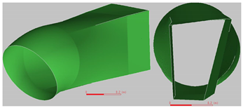
Energies 15 01275 i002
3.
A spiral in front of the runner, including an upward extension of the vertical shaft beyond the flow system;
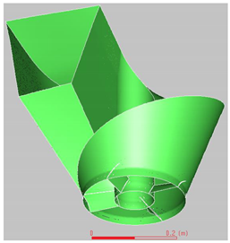
Energies 15 01275 i003
4.
Runners with a diameter of Ø265 mm (four and five blades);
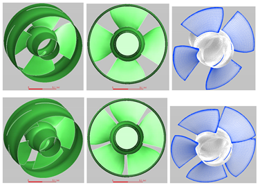
Energies 15 01275 i004
5.
A conical draft tube (axisymmetric);
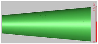
Energies 15 01275 i005
6.
An outlet pipe that was cylindrical apart from the elements belonging to the turbine (diameter Ø490 mm);
Energies 15 01275 i006
The shape of the runner blade of the model semi-Kaplan turbine is shown in Figure 7.
The calculations were made using the ANSYS/Fluent™ software, assuming the incompressibility of water (density ρ = const) and its viscosity for the assumed temperature of 15 °C (dynamic viscosity μ ≠ 0). The calculations used:
second-order discretization, i.e., the scheme of ‘second-order upwind’;
double-precision when solving;
at least 8000 iterations for each case;
a 2 m net head (hereinafter referred to as the reference head);
a k-ω SST turbulence model, where the computational mesh was created with a dimensionless distance from the wall Y+ below the value 3 (turbulence intensity at inlet: 3.14%; turbulence intensity at outlet: 3.06%), calculated based on the formula:
I = 16   R e 0.125 = 16   ρ   V   D μ R e 0.125   %
where V is the average flow velocity at the inlet or outlet, D is the hydraulic diameter at the inlet or outlet and ρ is the water density.
The SST k-ω turbulence model was chosen because is especially dedicated to calculations when an incompressible medium is used. It directly solves the turbulent equations for the kinetic energy of turbulence (k) and its frequency (ω). This means that the shear stresses in the boundary layer are calculated directly using the differential equations. The distribution of a boundary layer is not calculated using the power law. This is especially important when calculating the efficiency in a scenario where evaluating the friction is especially significant for the quality of calculations [35].
To ensure a constant systematic error and a high quality of calculation results for all analyzed cases, the same boundary conditions and the flow initiation method were adopted for the calculations. In addition, it should be emphasized that all results of the calculated power and flow rate—which due to differences of the analyzed cases, meant that the resulting net head slightly differed from the reference head—were then reduced to the reference head of 2 m, according to the general rules for reducing these values.
As part of the research, computational mesh for two types of runners were generated. The numbers of elements (entirely hexahedral cells) of the computational mesh are summarized in Table 1. The efficiencies obtained from CFD analyses are presented in Figure 8 and Figure 9 (these figures contain the markings, e.g., W10, which means the 10° runner blade opening).
In the case of the four-blade variant, the highest efficiency achieved was ~89.0%, with a reduced flow rate of 0.115 m3/s and a reduced power of ~2000 W.
The solution with the five-blade variant allowed us to achieve an efficiency of ~87.7%, with a reduced flow rate of 0.125 m3/s and a reduced power of ~2150 W.
In the case of the four-bladed runner, the turbine has a higher efficiency, which indicates that this option is better for lower heads than the five-bladed runner.

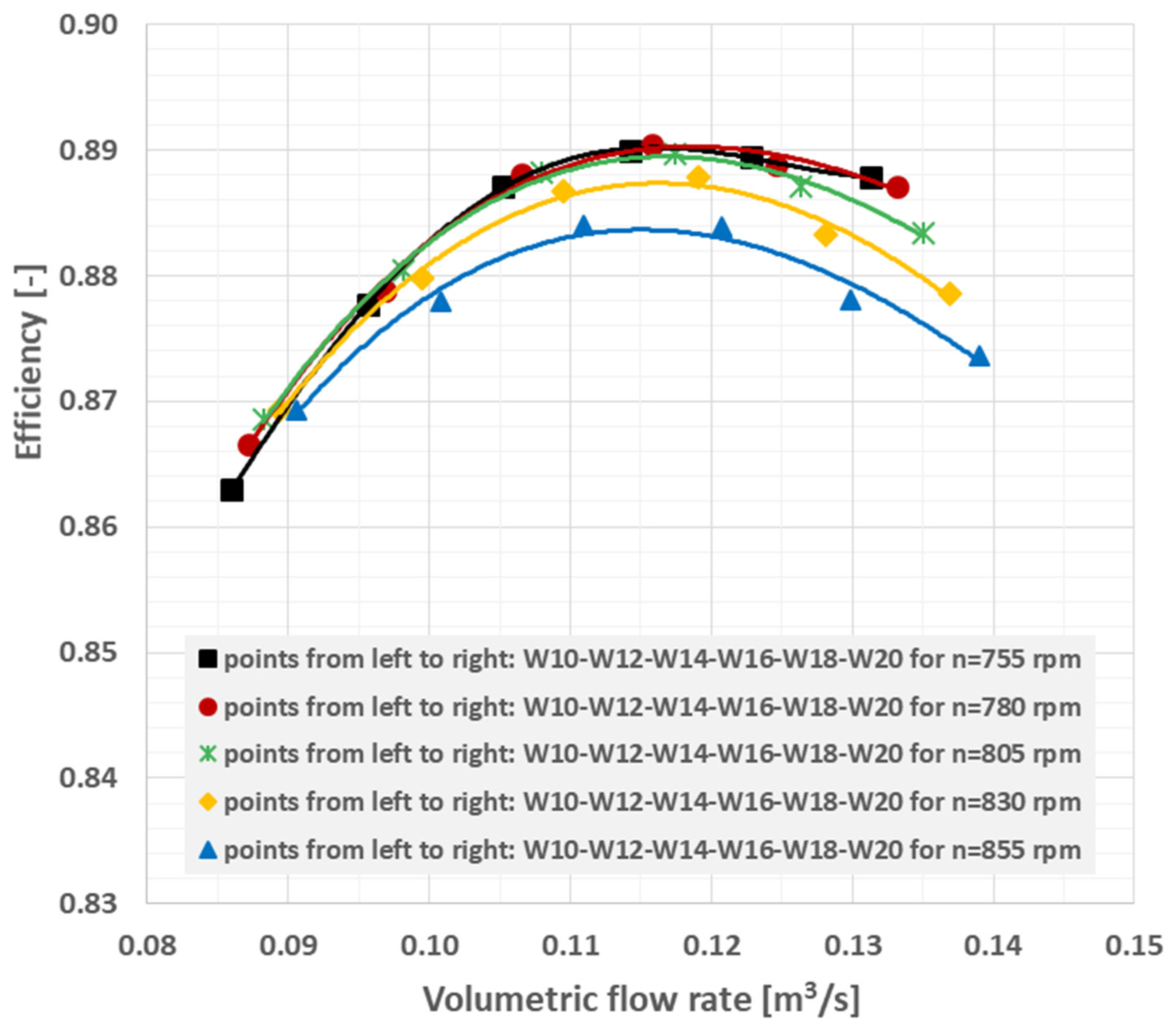
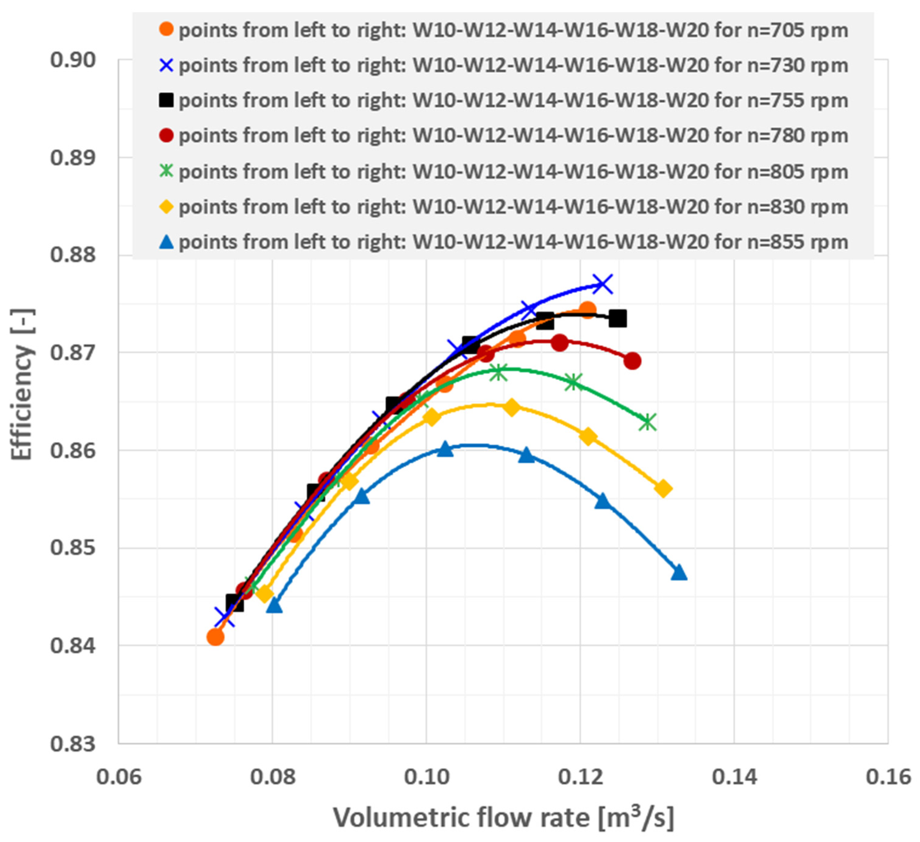
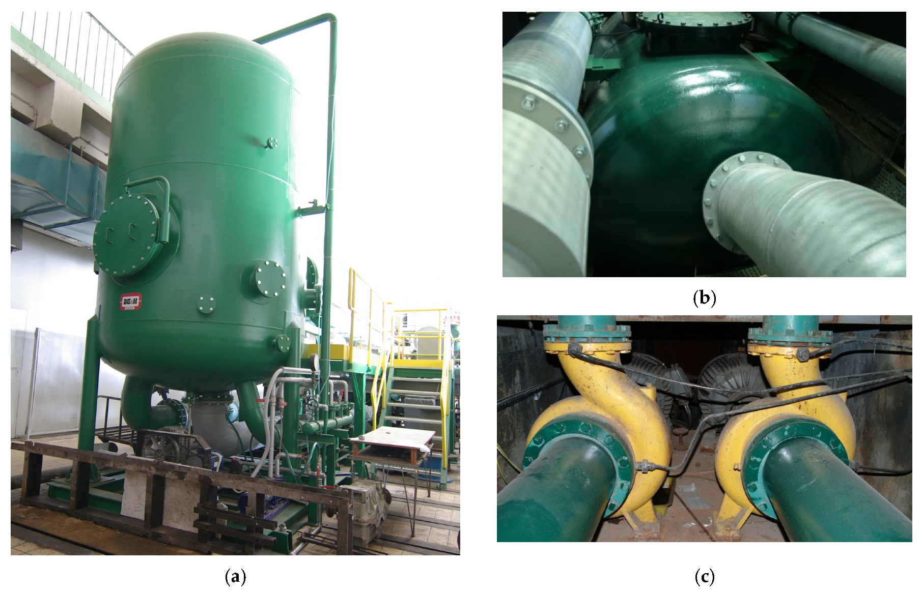
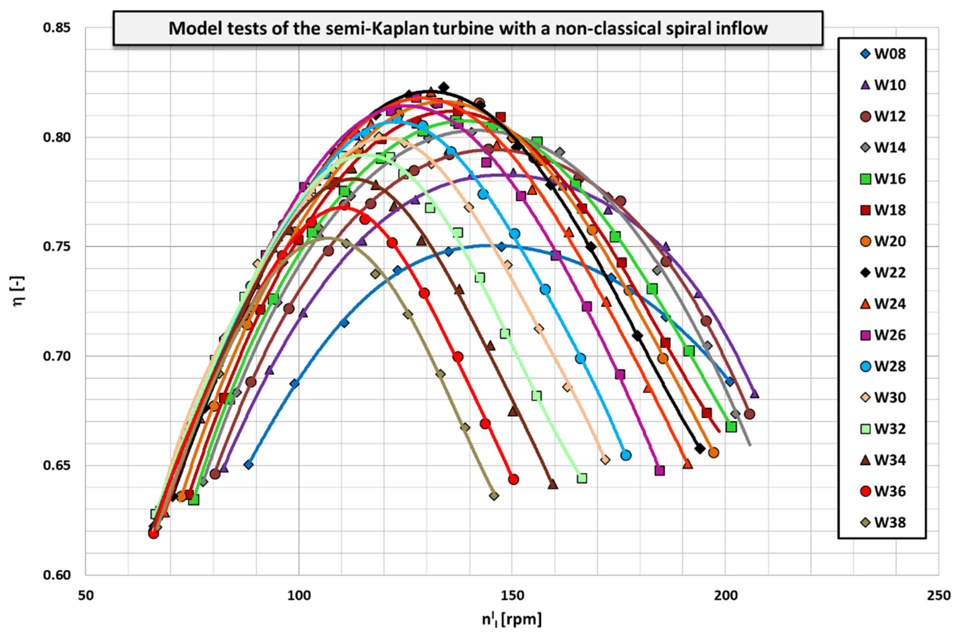
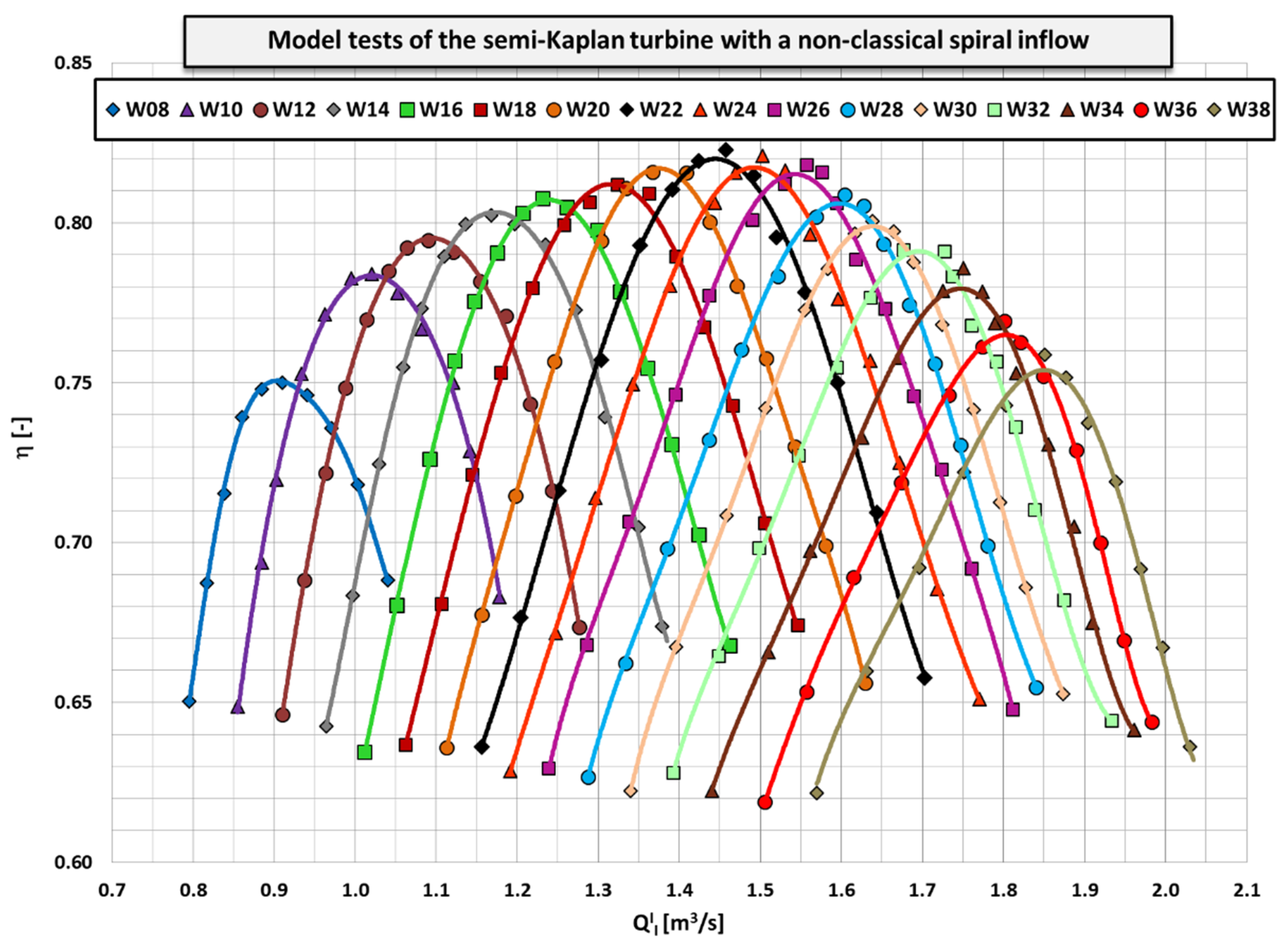
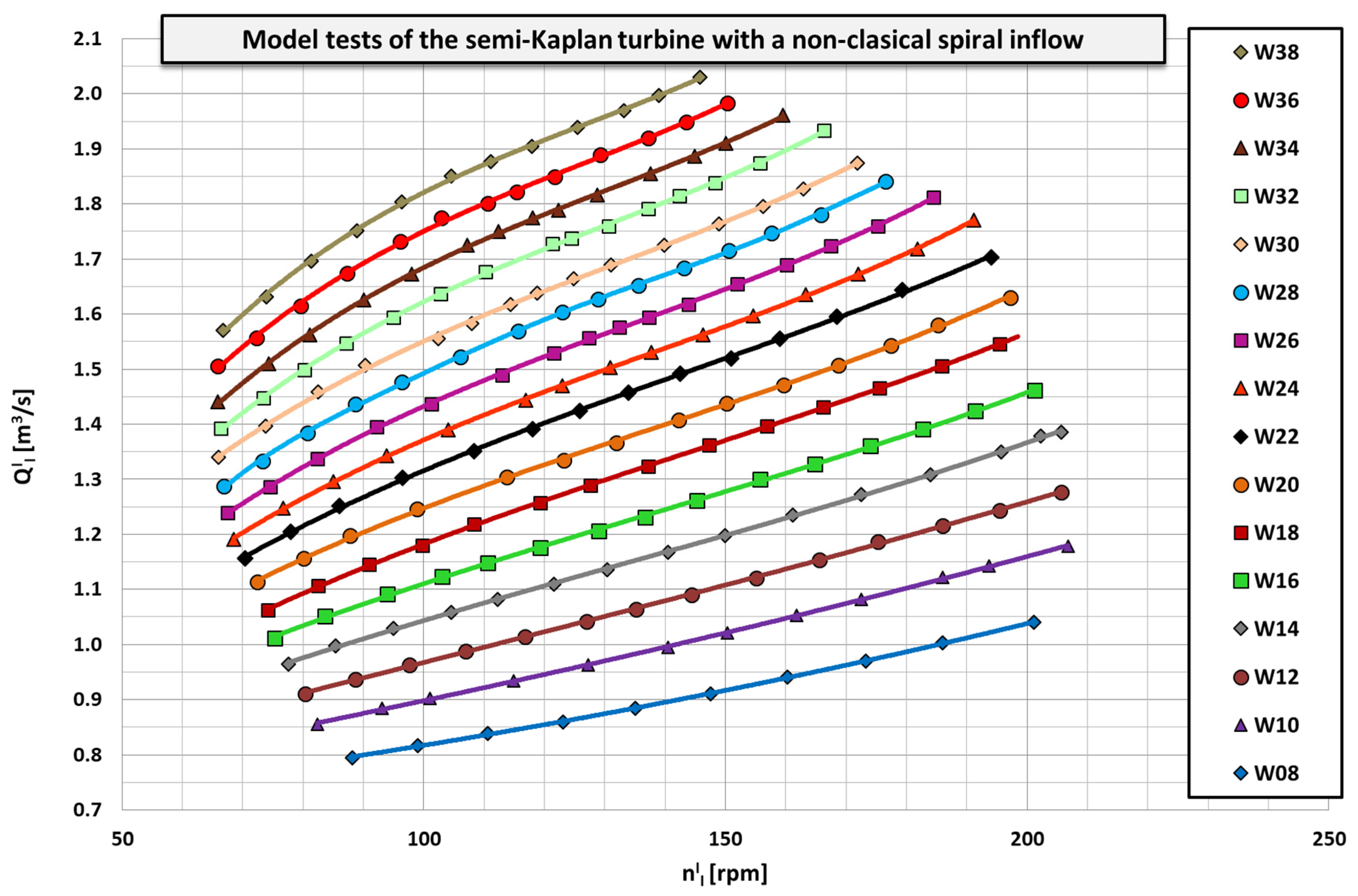
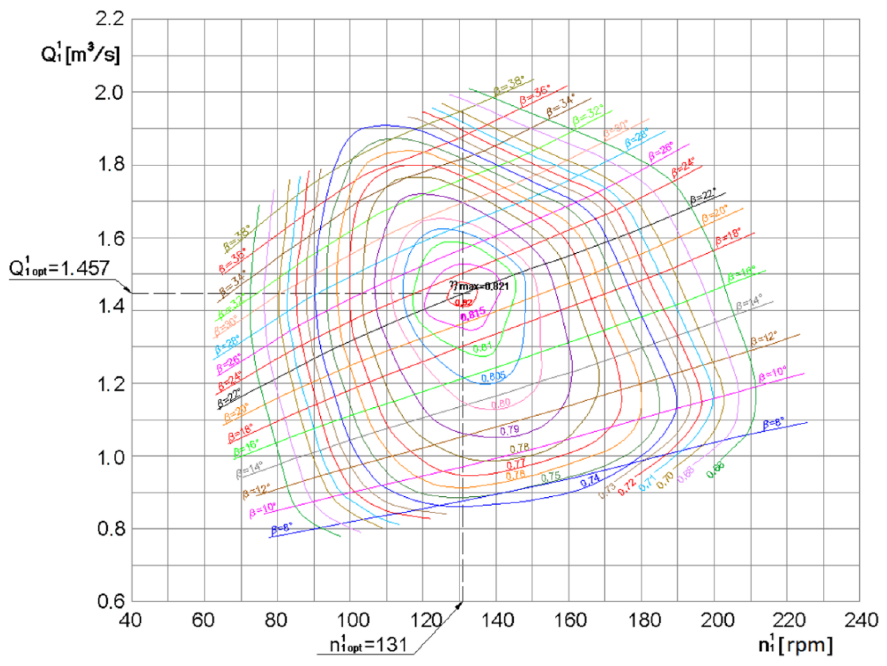
3.2.2. Model Tests of the Flow System

We decided to conduct model tests for the variant of the four-blade semi-Kaplan turbine. The net reference head, on which the laboratory tests were performed, was maintained at the level of 2 m of water. Under this assumption, the turbine has a rated power of approximately 2.3 kW, a flow rate of approximately 0.145 m3/s, and a rotational speed of approximately 720 rpm. The research was carried out on a laboratory stand at the Institute of Fluid-Flow Machinery of the Polish Academy of Science (IFFM) in Gdańsk, Poland, on which Kaplan and Francis turbines can be investigated in a wide range of operating conditions [36,37].
The flow elements of the tested turbine mounted on the laboratory stand were as shown in Figure 5. Before the inlet of the system, there was a straight pipeline with a diameter of ~Ø400 mm, supplying water to the turbine from the upper water tank of the laboratory stand.
The runner blades were adjusted when the turbine was at a standstill after draining the water (no adjustment system), by loosening the mounting bolts using the inspection window, made for this purpose in the runner housing.
Behind the runner, the conical axisymmetric draft tube was connected to the lower water tank. The turbine runner shaft was led upwards and connected to the generator via a torque meter mounted on both of its sides in disk clutches. A permanent magnet AC synchronous generator was placed on a support frame, rigidly connected to the spiral unit guiding water onto the runner.
A cross-section of the intake system with the runner is shown in Figure 10. Pictures of the inlet system of the tested turbine are shown in Figure 11, while the laboratory test stand is shown in Figure 12.
Basic laboratory tests were performed with a reference net head of 2 m, for 16 settings of the runner blades openings: 8°, 10°, 12°, 14°, 16°, 18°, 20°, 22°, 24°, 26°, 28°, 30°, 32°, 34°, 36° and 38°. As a result, the energy characteristics (propeller curves) of the model turbine were established (Figure 13, Figure 14 and Figure 15).
In this research, the following parameters were obtained at the optimal operating point of a model semi-Kaplan turbine:
  • angular setting of the runner blades: 22°;
  • rotational speed: n = ~714 rpm;
  • volumetric flow rate: Q = ~0.144 m3/s;
  • turbine efficiency: η = ~82.1%;
  • kinematic specific speed: n s Q = ~160;
  • dynamic specific speed: n s N 3.65   η   n s Q = ~530;
  • double-reduced rotational speed: n 1 1 = ~131 rpm;
  • double-reduced volumetric flow rate: Q 1 1 = ~1.457 m3/s.
The above-mentioned parameters were defined as follows. The turbine efficiency was calculated using the formula:
η = P r e d P t h
where Pred is the reduced power on a reference net head [W] and Pth is the theoretical power of water flowing into the turbine [W]. Both quantities were calculated using the formulas:
P r e d = P H n H r e f 1.5
P t h = ρ   g   Q r e d   H r e f
where P is the measured power on shaft [W], Hn is the measured net head [m], Href is the reference head (2 m), ρ is the density (999.1 m3/s), g is the gravitational acceleration (9.81 m/s2) and Qred is the reduced volumetric flow rate [m3/s].
The net head was calculated using the formula:
H n = Δ p ρ   g + V i n 2 V o u t 2 2   g + z i n z o u t = 0
where Δp is the pressure difference between the inlet and outlet of the measurement cross-sections of the turbine and Vin and Vout are the mean velocities at the inlet and outlet of the measurement cross-sections of the turbine, respectively. The velocities were calculated using the formulas:
V i n = Q A i n
V o u t = Q A o u t
where Q is the measured volumetric flow rate [m3/s], A i n is the inlet area of the measurement cross-section of the turbine (0.092212 m2), A o u t is the outlet area of the measurement cross-section of the turbine (0.182921 m2) and z i n and z o u t were the levels of the central points of the measurement cross-sections (the pressure was measured using a differential pressure transducer so it was equal zero).
The above-mentioned measurement cross-sections are shown in Figure 6. The inlet cross-section was located at the junction of elements two and three and the outlet cross-section was located at the junction of elements five and six. The reduced volumetric flow rate on a reference net head:
Q r e d = Q H n H r e f 0.5
The double reduced rotational speed (reduction of rotational speed for a machine with a runner diameter of 1 m working under a head of 1 m) was calculated using the formula:
n I I = n   D H n 0.5
where n is the rotational speed [rpm] and D is the diameter of the runner (0.265 m).
The double reduced volumetric flow rate (reduction of volumetric flow rate for a machine with a runner diameter of 1 m working under a head of 1 m) was calculated using the formula:
Q I I = Q H n 0.5 D 2
The kinematic specific speed was calculated using the formula:
n s Q = n Q 1 2 H n 3 4
The dynamic specific speed was calculated using the formula:
n s N 3.65   η   n s Q   %
The reason for obtaining a lower efficiency compared to CFD analyses may be, among others, the small dimensions of the turbine, which along with the linear reduction in dimensions, disproportionately negatively affect turbine efficiency. As a result of the so-called scale effect, along with an increase in the dimensions of the machine, as well as a higher head, the generated losses are going to be smaller, thus increasing the efficiency of the turbine. The increase in flow efficiency could also be achieved by the possible reduction of the runner’s over-blade gap. The gap size in the subject turbine runner was approximately 0.9 mm. The area resulting from the suprascapular gap was ~1.7% of the flow area (when assuming a hub diameter of Ø115 mm). The presence of the gap always causes volumetric losses in the flow, and consequently, reduces the turbine efficiency. It should be added that the tip flow is characterized by complicated vortex structures, which can further intensify the volumetric losses. It seems possible that we can reduce the height of the gap to just 0.5 mm, which will increase the efficiency of the turbine.

3.2.3. Energy Parameters of Turbines

Based on the results of the performed model tests, a so-called universal (shell) characteristic for turbine selection was developed. Thanks to this characteristic, it is possible to select turbines such as those working under other heads and flow rates. The universal characteristic (see Figure 16) is the dependence of the turbine efficiency η on the double-reduced rotational speed n 1 1 and the double-reduced volumetric flow rate Q 1 1 . Detailed procedures for energy tests, which determined the performance of the characteristics, were taken from [38,39]. The universal characteristic is presented in Figure 16.
The test results for the model turbine can be transferred to the conditions of similar prototype turbines at real hydropower sites using the laws resulting from the hydraulic similarity of rotating machines and the scale effect resulting from the inability to keep the same Reynolds number.
In our work, the procedures for rescaling the energy parameters of the model of a four-blade semi-Kaplan turbine to suit that of the real (prototype) system were taken from standards [38,39] concerning model acceptance tests of hydraulic turbines, storage pumps and pump turbines.
Based on the results of the tests for the four-blade vertical semi-Kaplan turbine model using the laws of similarity of hydraulic machines, a series of prototype turbines were developed for six values of characteristic runner diameters ranging from 0.5 to 1.6 m and for nine values of heads ranging from 1 to 10 m (Figure 17).
As a result of scaling the efficiency of the model turbine (determining the scale change effect) for a similar machine with the largest assumed runner diameter (D = 1.6 m) and working under the largest assumed head (H = 10 m), the highest efficiency gains Δη were obtained for the optimal operation point of the prototype turbine, amounting to Δη = 4.82%. The absolute maximum efficiency value reached η = 86.92% in this configuration.
The projected parameters for this prototype turbine at the optimal operating point were:
  • power on the turbine shaft:
Popt = 1006 kW;
  • volumetric flow rate:
Qopt = 11.79 m3/s;
  • rotational speed:
n = 258.9 rpm.
The indicated solution, from the point of view of the flow rate, may be dedicated to more medium-sized heads. This is due to the value achieved for the double-reduced volumetric flow rate ( Q 1 1 = 1.457 m3/s), which is lower when compared to tubular turbines designed to operate at low heads.
The tested turbine undoubtedly has a significant advantage, as it seems a relatively simple and cheap alternative design solution when compared to classic but more complex solutions, such as, e.g., double-regulated turbines (Kaplan type).
From this point of view, its use on low heads can be economically justified, and therefore, it may be attractive for investors looking for low-budget design solutions for hydraulic turbines.

3.3. Electric Power Generation System

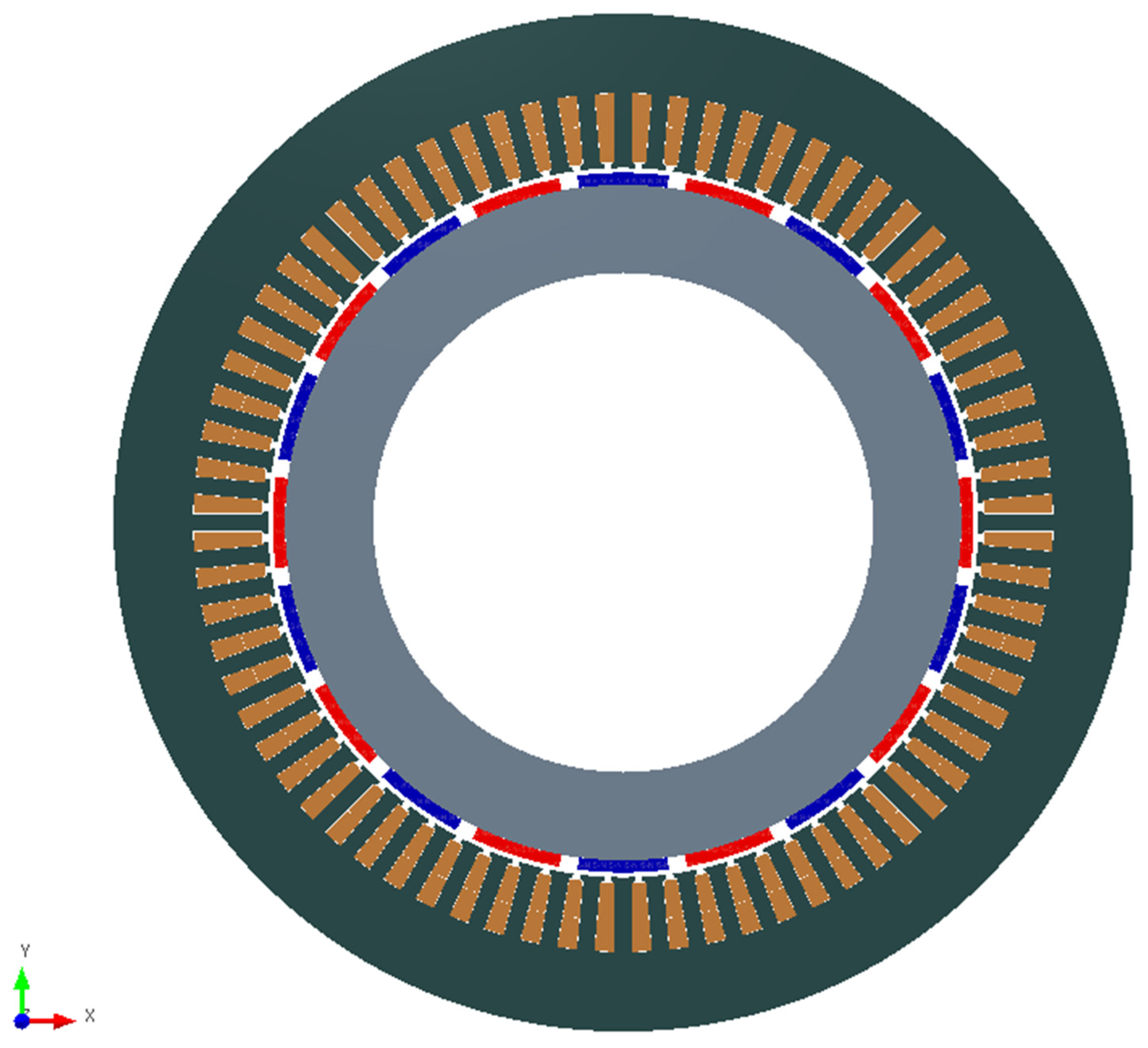
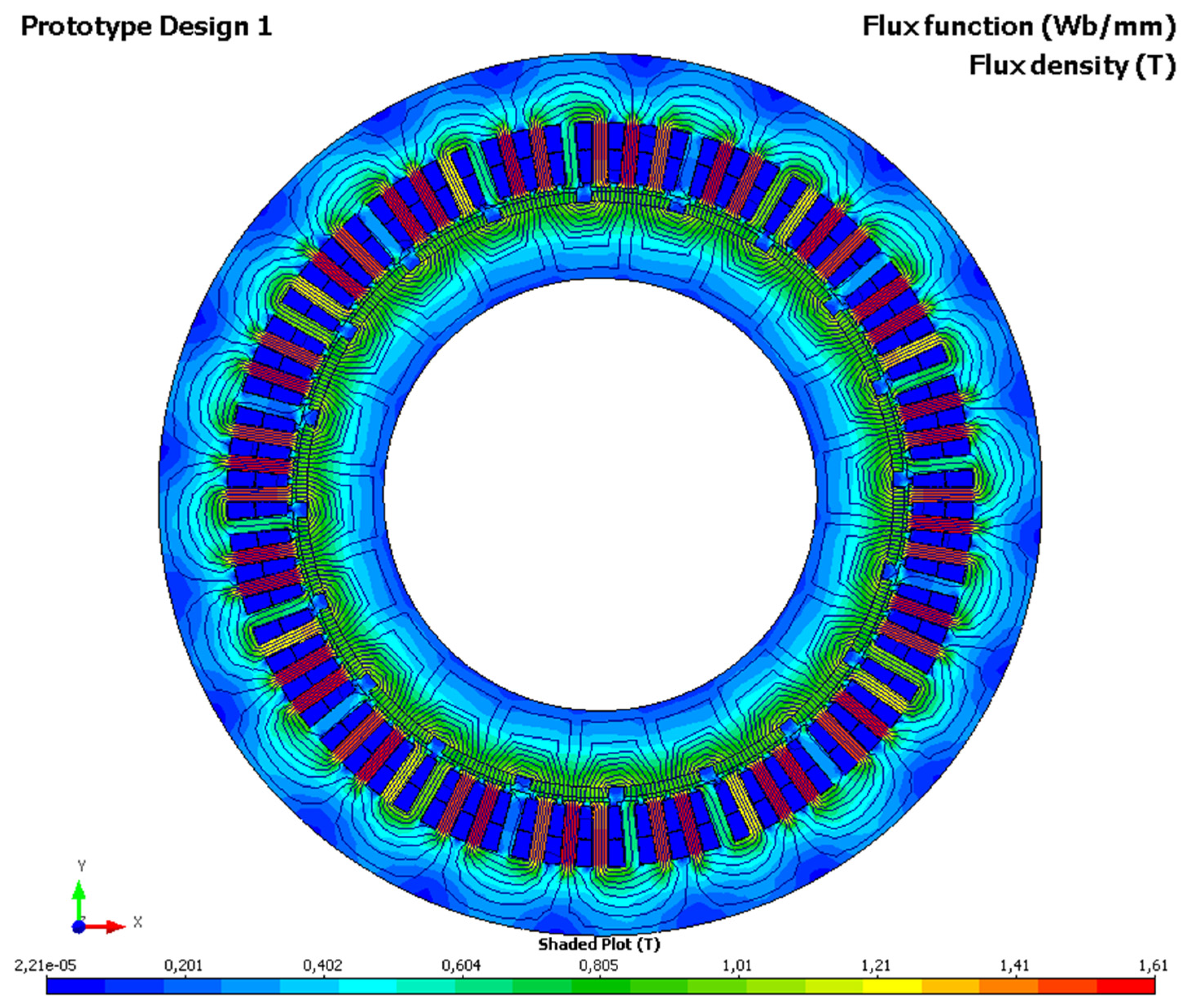
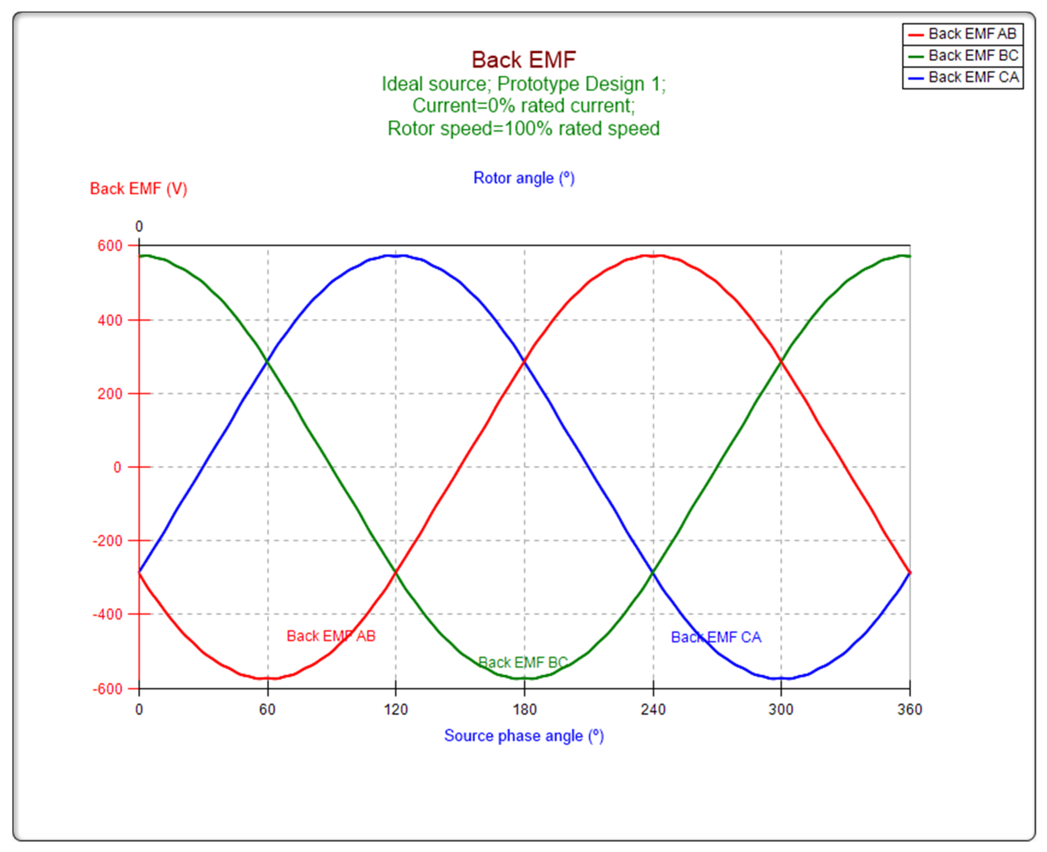
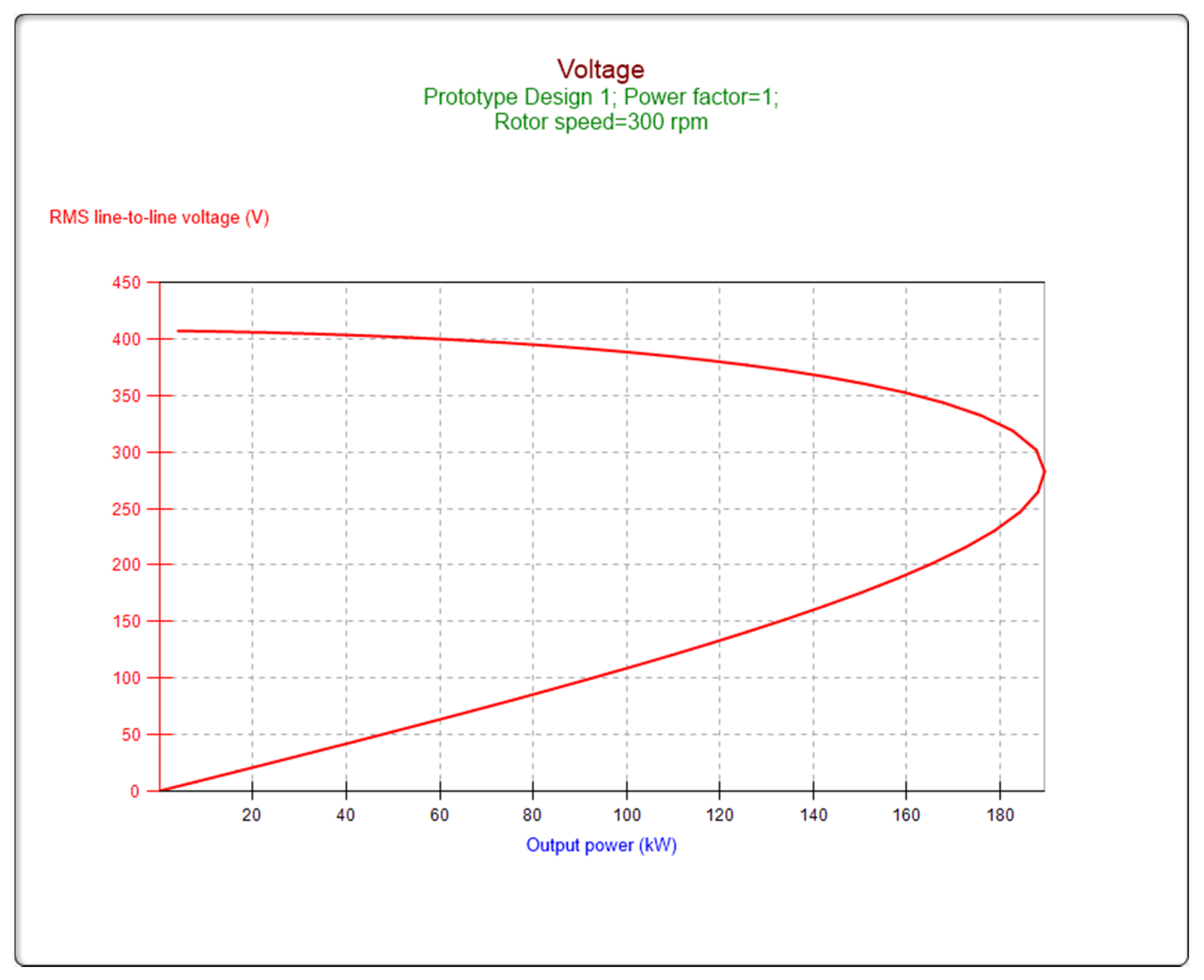
3.3.1. Permanent Magnet-Excited Generator

There are many offers on the commercial market for permanent magnet synchronous machines. They are often used in drive applications, but for regenerative operation in the specific speed range corresponding to the operation of hydraulic turbines, the choice is limited. Designing such a generator is not a very difficult task, but it requires certain knowledge and experience. Therefore, the authors decided to present an example project. An example generator design, to be made using existing stator packages for induction machines, was proposed. In line with this concept, the stator winding and permanent magnet rotor need to be developed. The authors propose rotor structures with magnets distributed over the surface of a cylindrical rotor [40,41,42,43,44]. This solution is one of the most advantageous for obtaining high efficiency of the generator. For example, by using the nomogram of the series of semi-Kaplan turbines (Figure 17) for a head of H = 4 m and a flow of Q = 1.5 m3/s, we can select a turbine with a diameter of D = 800 mm and a generator with rated data: power PN = 50 kW and rotational speed nN = 300 rpm. For this example, which can be considered representative of small objects, we will illustrate the design of a permanent magnet generator with a rated voltage and frequency of UN = 400 V and fN = 50 Hz.
As a starting point, we propose using stator sheets from the existing SZUc 176b asynchronous motor. The authors applied the INFOLYTICA-MagNet MotorSolver tools to structure optimization analyses, based on FEM analyses and analytical models [40,41,42,43,44]. Table 2 summarizes the main dimensions of the generator obtained from the model calculations.
Figure 18 and Figure 19 show the generator cross-section and the magnetic field distribution, from which we can conclude that there are no excessive magnetic flux density values in the teeth and yokes that would lead to saturation and increased sheet loss. The induced EMF waveforms and the harmonic content analysis presented in Figure 20 and Figure 21 also confirm the relatively low degree of waveform distortion from the sinusoidal shape.
The external characteristic presented in Figure 22 shows a relatively small variation of the generator voltage under the rated load. The obtained generator efficiency of 96% (Figure 23) in the nominal conditions proves the correctness of the design’s data selection, according to Table 2. This confirms the earlier statement that permanent magnet generators have a higher efficiency than the asynchronous generators commonly used in SHP. The presented example for a generator’s design shows the possibilities of using the existing asynchronous machines by adapting the stator sheet package, shaft, bearing and housing. The design process is limited to electromagnetic issues, i.e., the construction of the stator winding, and the selection of permanent magnets mounted on the rotor surface, which is a homogeneous steel ring. This approach allows us to significantly reduce the cost of the generator’s manufacture.

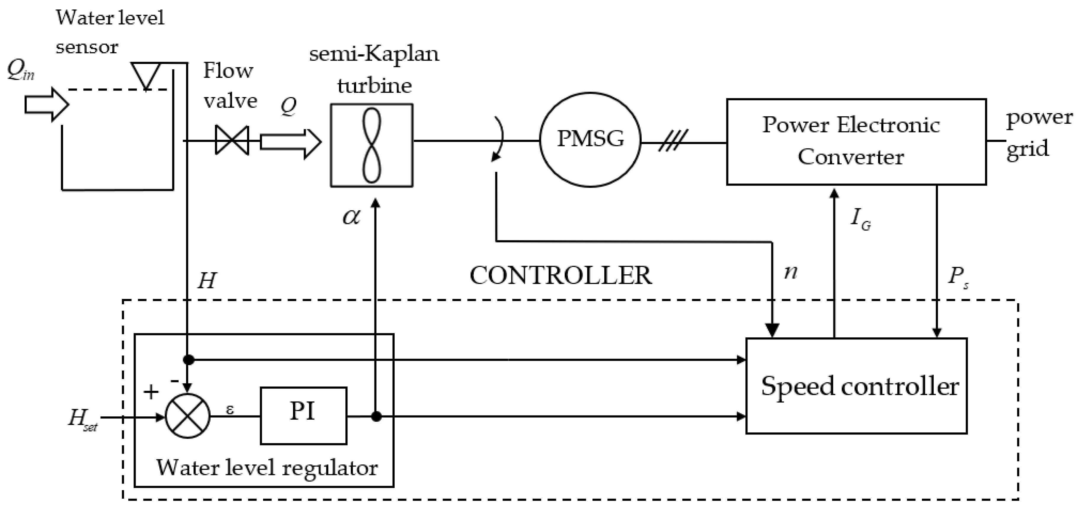
3.3.2. Power Electronic Converter in the SHP Control System

The possibilities for energy conversion and the use of power electronic converters have been subjected to numerous analyses, including by the authors, e.g., in papers [31,32,33,34].
For small power systems, a full-scale PEC is used due to its wide operating range (speed range) [15]. This solution is also recommended for SHP.
The most common structure of a PEC is a back-to-back (AC/DC/AC) voltage source converter with a DC link circuit [19,20,21,22,31]. The machine-side converter is usually a force-commutated rectifier [15]. Low-power applications allow the use of a simple two-level converter, which provides independent active and reactive power controls for the machine-side and grid-side converters. The standard sinusoidal pulse width modulation (SPWM) technique of a DC/AC converter is often replaced by the space vector modulation (SVM) technique that generates modulation signals based on the switching sector and angle. Compared to the standard SPWM, the SVM generates waveforms with less THD (total harmonic distortion) and allows for a higher maximum modulation index with smaller switching losses [32]. The vector-based control strategies used in PECs can be divided into voltage-oriented control (VOC) and direct-power control (DPC). In VOC, the active and reactive power are controlled indirectly depending on the mutual orientation of two vectors, the current and line voltage, whereas the DPC controls instantaneous values of the active and reactive power. In both these methods, the current waveform is influenced by voltage distortion. There are several studies on how to modify these two methods, e.g., by using a DPC with a constant switching frequency and space-vector modulation (DPC-SVM). The DPC-SVM technique is relatively simple, does not require a line voltage sensor, offers a low THD current for the distorted voltage and requires only a low switching frequency [33].
Energy-converter systems are quite often used in wind farms if the source of energy is a synchronous generator with permanent magnets. However, we should emphasize that the range of changes in the rotational speed of windmill-driven generators is much smaller than for SHPs. Moreover, the method of controlling the operation of the hydro unit through the converter is also different due to the specific shape of the mechanical characteristics of hydraulic turbines [26,27,28,29,30]. The hydropower plant control algorithm should perform two functions. The basic task is to control the hydrological parameters, i.e., the level of upper water or the flow rate of the turbine. For run-of-river power plants, unchanging hydrological conditions must be maintained, i.e., the upper water level at a given constant value. This is the main task of the water-level controller. As a result of this control, a certain volume of water is fed to the hydraulic turbine. Optimal conversion of this flow into electric power requires appropriate control of the rotational speed of the turbine, which is the second important task carried out by the control algorithm. In power plants using the variable speed technique, the upper water-level controller controls the angle of the steering blades for propeller turbines or the angle of the blades of the runner in the case of semi-Kaplan turbines [26,27,28,29,30]. A gate or flow valve (e.g., the butterfly type) is used to completely close the flow. In turn, the speed controller controls the optimal operating conditions for the turbine, i.e., the maximum processing efficiency. The described structure of the control algorithm is presented in Figure 24.
Separating the water-level controller from the task of optimizing the parameters of the turbine (speed controller), as result from the operation of this type of facility, ensures stable operation of the turbine. The use of a classic PI regulator with a long time constant for this purpose eliminates sudden changes in the valve opening, which prevents sudden pressure surges, which in turn, reduces the wear on the mechanical elements of the turbine flow system. Optimizing control of the hydraulic turbine by selecting the optimal rotational speed for specific operating conditions is crucial for maximizing the energy generation of a power plant. This is since the hydraulic turbine is characterized by the greatest variety of efficiency compared to a generator and power electronic converter.
This task is difficult because the performance characteristic depends on many factors and it is difficult to predict theoretically. To solve this problem, various methods can be used to control the rotational speed of the turbine [19,20,21,22,26,27,28,29,30]. The easiest way is to control it using databases to obtain the characteristics of the hydro unit, as determined in measurements and model tests.
In this way, databases of the characteristics from the hydro unit and other elements of the system, obtained from measurements and model tests, are used. The main disadvantage of this solution is the difficulty of obtaining data. Additionally, the parameters of the system components, especially the hydraulic turbine, change during operation. Yet, this method does not have a mechanism to adapt the control to the current turbine condition or hydrological conditions. On the other hand, the advantage of this solution is the high control dynamic resulting from a strictly defined work curve, which is defined for any hydrological condition.

4. Discussion

This paper presented a semi-Kaplan type of turbine, designed for use in small hydropower plants characterized by low heads, i.e., with low hydro potential. The presented solution is technologically simple, cheap and can be used in a wide range and with great variability of operating parameters, on a nationwide power grid and on a separate one, too. Thanks to the use of a PM generator, it is possible to adjust the hydro unit depending on the changing current parameters, which in the case of small hydropower plants, range from a few to several hundred percent, both in terms of the water head and water flow rate.
There are still few such cases of developments for low-head hydropower plants in the literature. This seems to be since the current focus is now mainly on other renewable energy sources such as wind, sun and gas from biomass.
Yet, this paper follows the current global trend in the hydropower industry to use the places with the lowest water potential, as water-based energy is the most stable form of renewable energy. We are interested in developing solutions for the lowest dams, up to 5 m. For example, in Poland, according to official data, there are about 5000 possible sites where we could install small hydropower plants. This means there is enormous potential to be used, which should lead to a significant increase in energy production from low water heads, generating power obtained from a renewable energy source. Constructing a small hydroelectric power plant means not only energy production but also raising the surrounding groundwater and improving the possibility of controlled irrigation. In addition, it also holds the potential to make new tourist areas, or vice versa, high-quality areas reserved for birds and animals. Furthermore, such solutions can be easily adapted to be combined with other forms of renewable energy production (wind energy, solar energy, etc.).
It is important to add that the proposed solution should be constantly improved to increase the water flow rates, which will increase the energy production while maintaining a constant head. Such an action may reduce the costs of the machine as it reduces the dimensions of a hydro unit. We are working on further improvements to the most important modules of the hydro unit, i.e., a generator and another kind of turbine. We aim to develop devices with higher efficiencies and increased flow rates. This is especially important for low-power turbines to maximize energy production, which is assumed to be low compared to high-power plants due to low heads. Taking into account low water heads, the only way to increase energy production is to increase the water flow rate through the machine (in the next stage of work, the Kaplan turbine solution will be presented, which is designed for the lowest possible ultra-low heads (with high efficiency), i.e., less than 2 m).
Yet, the cavitation phenomenon presents a limitation to using low-head hydro units, i.e., hydro units characterized by high specific speeds. Constructing a machine to execute higher flow rates makes the unit more susceptible to cavitation. This means that such machines must be placed low down to suit the lower water level of the hydropower plant. This is difficult because in the case of low-power hydropower plants (up to 100 kW), it is sometimes necessary to place the runner above the lower water level to reduce the cost of the foundation. Such an action increases the likelihood of cavitation in the flow, which may cause material erosion and gradually destroy machine components. The cheapest case of a low-head turbine is a turbine in a siphon system, i.e., with a runner located above the upper water. In the case of heads of about 3 m, operating such a turbine will probably be associated with cavitation. In that context, a safer variant may be the turbine with a spiral inflow and a four-blade runner presented in this paper. It is characterized by safer operation, with the runner above the lower water, due to lower flow rates than for a turbine with a three-blade runner. The latter has higher water-flow rates, and thus energy production, but at the same time, a greater tendency to lead to the cavitation phenomenon, which we must strive to avoid.

5. Conclusions

This paper presented an alternative design solution for how to integrate a hydraulic turbine with an electric generator, aimed at the modular construction of a hydro unit characterized by relatively high efficiency and reliability. This was achieved by eliminating the mechanical transmission and using a synchronous generator with permanent magnets. Additionally, we honed a control system for the electric energy conversion path using a power electronic converter. This solution enables the trouble-free operation of the generator with the power system and wide possibilities for regulation. An additional advantage is the ability to operate the hydro unit with variable rotational speeds, which makes it easier to adjust the operating parameters to a given location. Variable rotational speeds may bring additional benefits by simplifying the construction of the hydro unit. This possibility is particularly important because after turbine modeling tests, the turbine runner blade adjustment system can be eliminated. This is especially ley to the use of semi-Kaplan turbines with an unconventional spiral inflow, as proposed in this paper. Working with a variable rotational speed of the hydro unit allows high efficiency of energy conversion to be maintained for different values of the turbine’s flow rate, while simplifying the mechanical structure, which is characteristic for this type of turbine. The proposed solution for designing a semi-Kaplan turbine with a non-classical spiral water inflow is relatively cheap due to its simplicity, which makes it attractive for SHP applications.
It should also be emphasized that the currently introduced legal regulations on connecting generation units to power systems (Commission Regulation (EU) 2016/631 of 14 April 2016, commonly known as NC RfG) require complex control systems to be used in newly established or modernized power plants. Employing an inverter helps significantly with fulfilling these requirements and thus reduces the cost of equipping a small power plant.

Author Contributions

Conceptualization, D.L., Z.K., T.W., D.B., A.P., K.W. and A.C.; methodology, Z.K. and T.W.; validation, Z.K., T.W. and D.B.; investigation, Z.K., T.W. and K.W.; data curation, A.P., A.C. and T.W.; writing—original draft preparation, Z.K. and T.W.; writing—review and editing, D.L., Z.K., D.B., A.C. and T.W.; supervision, Z.K. and T.W.; software, Z.K. All authors have read and agreed to the published version of the manuscript.

Funding

This research was funded by the Polish National Center for Research and Development under the Intelligent Development Operational Program for 2014–2020, Axis 1: Support for R&D by enterprises, Measure 1.2: R&D programs, grant no. POIR.01.02.00-00-0251/16.

Conflicts of Interest

The authors declare that they are not aware of any conflicting financial interests or personal relationships that could affect the work reported in the paper.

Abbreviations

SHPSmall Hydropower Plants
PMPermanent Magnet
PECPower Electronic Converter
PMGPermanent Magnet Generator
SVMSpace Vector Modulation
SPWMSinusoidal Pulse Width Modulation
VOCVoltage-Oriented Control (VOC)
DPCDirect Power Control Reynolds-Averaged Navier–Stokes
SSTShear-Stress Transport
THDTotal Harmonic Distortion
FEMFinite Element Method

References

  1. Xu, J.; Ni, T.; Zheng, B. Hydropower development trends from a technological paradigm perspective. Energy Convers. Manag. 2015, 90, 195–206. [Google Scholar] [CrossRef]
  2. Sachdev, H.S.; Akella, A.K.; Kumar, N. Analysis and evaluation of small hydropower plants: A bibliographical survey. Renew. Sustain. Energy Rev. 2015, 51, 1013–1022. [Google Scholar] [CrossRef]
  3. Manzano-Agugliaro, F.; Taher, M.; Zapata-Sierra, A.; Juaidi, A.; Montoya, F.G. An overview of research and energy evolution for small hydropower in Europe. Renew. Sustain. Energy Rev. 2017, 75, 476–489. [Google Scholar] [CrossRef]
  4. Penche, C. Layman’s Guidebook on How to Develop a Small Hydro Site; ESHA: Bruselas, Belgium, 1998. [Google Scholar]
  5. Christ, A. Hydrostatic seals for large diameters. In Proceedings of the 9th International Conference of Fluid Sealing, Noordwijkerhout, The Netherlands, 1–3 April 1981. [Google Scholar]
  6. Hopper, H.R.; Mayer, H.W.; Severn, B. Manitoba HYDRO and STRAFLO Units. In Proceedings of the 92nd E.I.C. Annual Congress, St. John’s, NL, Canada, 25–26 May 1978. [Google Scholar]
  7. Frust, A. Ausbau des Rheinkraftwerks Laufenburg—Fünf Jahre Betriebserfahrung mit Straflo-Turbinen. Bulletin 1998, 2, 25–29. [Google Scholar]
  8. Schiffer, J. Experimental investigation of the rim-lip seal of a double regulated Straflo Kaplan turbine under extreme conditions. In Promoting the Versatile Role of Hydro, Proceedings of the Hydro—International Conference and Exhibiton—Innsbruck, Austria 7–10 October 2013; Aqua~Media International Ltd.: Wallington, UK, 2013. [Google Scholar]
  9. Gautam, N.; Rentschler, A.; Schneider, T.; Binder, A. Modeling and analysis of parallel connected permanent magnet synchronous generators in a small hydropower plant. WSEAS Trans. Power Syst. 2006, 1, 825–830. [Google Scholar]
  10. Xiaoli, C.; Binder, A.; Schlemmer, E. Straight-Flow permanent magnet synchronous generator design for small hydro power plants. In Proceedings of the 2007 International Conference on Clean Electrical Power, Capri, Italy, 21–23 May 2007; pp. 323–328. [Google Scholar]
  11. Borkowski, D.; Węgiel, T. Small Hydropower Plant with Integrated Turbine-Generators Working at Variable Speed. IEEE Trans. Energy Convers. 2013, 28, 452–459. [Google Scholar] [CrossRef]
  12. Węgiel, T.; Borkowski, D.; Liszka, D. Efficiency analysis of an energy conversion system for a variable speed small hydropower plant. In Proceedings of the International Conference on the Sustainable Energy and Environment Development (SEED), Kraków, Poland, 17–19 May 2016. [Google Scholar] [CrossRef] [Green Version]
  13. Borkowski, D.; Węgiel, M.; Ocłoń, P.; Węgiel, T. CFD model and experimental verification of water turbine integrated with electrical generator. Energy 2019, 185, 875–883. [Google Scholar] [CrossRef]
  14. KWI Architects Engineers Consultants. Status Report on Variable Speed Operation in Small Hydropower; Energie: St. Pölten, Austria, 2000. [Google Scholar]
  15. Nababan, S.; Muljadi, E.; Blaabjerg, F. An overview of power topologies for micro-hydro turbines. In Proceedings of the 2012 3rd IEEE International Symposium on Power Electronics for Distributed Generation Systems (PEDG), Aalborg, Denmark, 25–28 June 2012; pp. 737–744. [Google Scholar]
  16. Iliev, I.; Trivedi, C.; Dahlhaug, O.G. Variable-speed operation of Francis turbines: A review of the perspectives and challenges. Renew. Sustain. Energy Rev. 2019, 103, 109–121. [Google Scholar] [CrossRef]
  17. Fraile-Ardanuy, J.; Wilhelmi, J.R.; Fraile-Mora, J.J.; Pérez, J.I. Variable-Speed hydro generation: Operational aspects and control. IEEE Trans. Energy Convers. 2006, 21, 569–574. [Google Scholar] [CrossRef]
  18. Valavi, M.; Nysveen, A. Variable-Speed Operation of Hydropower Plants: A Look at the Past, Present, and Future. IEEE Ind. Appl. Mag. 2018, 24, 18–27. [Google Scholar] [CrossRef] [Green Version]
  19. Zhou, J.; Xu, Y.; Zheng, Y.; Zhang, Y. Optimization of Guide Vane Closing Schemes of Pumped Storage Hydro Unit Using an Enhanced Multi-Objective Gravitational Search Algorithm. Energies 2017, 10, 911. [Google Scholar] [CrossRef]
  20. Bortoni, E.; Souza, Z.d.; Viana, A.; Villa-Nova, H.; Rezek, Â.; Pinto, L.; Siniscalchi, R.; Bragança, R.; Bernardes, J., Jr. The Benefits of Variable Speed Operation in Hydropower Plants Driven by Francis Turbines. Energies 2019, 12, 3719. [Google Scholar] [CrossRef] [Green Version]
  21. Guo, B.; Mohamed, A.; Bacha, S.; Alamir, M.; Boudinet, C.; Pouget, J. Reduced-Scale Models of Variable Speed Hydro-Electric Plants for Power Hardware-in-the-Loop Real-Time Simulations. Energies 2020, 13, 5764. [Google Scholar] [CrossRef]
  22. Wang, H.; Ma, Z. Regulation Characteristics and Load Optimization of Pump-Turbine in Variable-Speed Operation. Energies 2021, 14, 8484. [Google Scholar] [CrossRef]
  23. Borkowski, D.; Majdak, M. Small hydropower plants with variable speed operation—an optimal operation curve determination. Energies 2020, 13, 6230. [Google Scholar] [CrossRef]
  24. Gao, J.; Dai, L.; Liu, X.; Du, X.; Luo, D.; Huang, S. Variable-Speed Hydropower Generation: System Modeling, Optimal Control, and Experimental Validation. IEEE Trans. Ind. Electron. 2021, 68, 10902–10912. [Google Scholar] [CrossRef]
  25. Belhadji, L.; Bacha, S.; Munteanu, I.; Rumeau, A.; Roye, D. Adaptive MPPT Applied to Variable-Speed Microhydropower Plant. IEEE Trans. Energy Convers. 2013, 28, 34–43. [Google Scholar] [CrossRef]
  26. Borkowski, D. Maximum Efficiency Point Tracking (MEPT) for Variable Speed Small Hydropower Plant with Neural Network Based Estimation of Turbine Discharge. IEEE Trans. Energy Convers. 2017, 32, 1090–1098. [Google Scholar] [CrossRef]
  27. Borkowski, D. Analytical Model of Small Hydropower Plant Working at Variable Speed. IEEE Trans. Energy Convers. 2018, 33, 1886–1894. [Google Scholar] [CrossRef]
  28. Iman-Eini, H.; Frey, D.; Bacha, S.; Boudinet, C.; Schanen, J. Evaluation of loss effect on optimum operation of variable speed micro-hydropower energy conversion systems. Renew. Energy 2019, 131, 1022–1034. [Google Scholar] [CrossRef]
  29. Guo, B.; Bacha, S.; Alamir, M.; Imaneinc, H. An anti-disturbance ADRC based MPPT for variable speed micro-hydropower plant. In Proceedings of the IECON 2017—43rd Annual Conference of the IEEE Industrial Electronics Society, Beijing, China, 29 October–1 November 2017; pp. 1783–1789. [Google Scholar] [CrossRef]
  30. Borkowski, D. Identification of the Optimal Control Characteristics of a Small Hydropower Plant Using Artificial Neural Networks and the Support Vector Machines Method. J. Hydraul. Res. 2019, 57, 715–723. [Google Scholar] [CrossRef]
  31. Joseph, A.; Chelliah, T.R. A Review of Power Electronic Converters for Variable Speed Pumped Storage Plants: Configurations, Operational Challenges, and Future Scopes. IEEE J. Emerg. Sel. Top. Power Electron. 2018, 6, 103–119. [Google Scholar] [CrossRef]
  32. Gupta, A.K.; Khambadkone, A.M. A space vector PWM scheme for multilevel inverters based on two-level space vector PWM. IEEE Trans. Ind. Electron. 2006, 53, 1631–1639. [Google Scholar] [CrossRef]
  33. Malinowski, M.; Jasiński, M.; Kaźmierkowski, M.P. Simple direct power control of three-phase PWM rectifier using space-vector modulation (DPC-SVM). IEEE Trans. Ind. Electron. 2004, 51, 447–454. [Google Scholar] [CrossRef]
  34. Sobczyk, T.; Mazgaj, W.; Szular, Z.; Wegiel, T. Higher harmonics of converter currents in energy conversion system of small water plants. In Proceedings of the 2011 IEEE International Symposium on Industrial Electronics (ISIE), Gdansk, Poland, 27–30 June 2011; IEEE: New York, NY, USA, 2011. [Google Scholar]
  35. Krzemianowski, Z.; Banaszek, M.; Tesch, K. Experimental validation of numerical model within a flow configuration of the model kaplan turbine. Mech. Mech. Eng. 2011, 15, 297–307. [Google Scholar]
  36. Krzemianowski, Z.; Steller, J. High specific speed Francis turbine for small hydro purposes—design methodology based on solving the inverse problem in fluid mechanics and the cavitation test experience. Renew. Energy 2021, 169, 1210–1228. [Google Scholar] [CrossRef]
  37. Krzemianowski, Z. Engineering design of the low-head Kaplan hydraulic turbine blades using the inverse problem method. Bull. Pol. Acad. Sci. Tech. Sci. 2019, 67, 1133–1147. [Google Scholar]
  38. Norm IEC 60041:1994; Field Acceptance Tests to Determine the Hydraulic Performance of Hydraulic Turbines, Storage Pumps and Pump-Turbines. International Electrotechnical Commission (IEC): London, UK, 1994.
  39. Norm IEC 60193:1999; Hydraulic Turbines, Storage Pumps and Pump-Turbines. Model Acceptance Tests. International Electrotechnical Commission (IEC): London, UK, 1999.
  40. Zhu, Z.Q.; Howe, D. Influence of design parameters on cogging torque in permanent magnet machines. IEEE Trans. Energy Convers. 2000, 15, 407–412. [Google Scholar] [CrossRef] [Green Version]
  41. Gieras, J.F.; Wing, M. Permanent Magnet Motor Technology; Marcel Dekker, Inc.: New York, NY, USA, 2002. [Google Scholar]
  42. Hanselman, D.D. Brushless Permanent Magnet Motor Design; The Writers’ Collective: Orono, ME, USA, 2003. [Google Scholar]
  43. Juha Pyrhonen, T.J.; Hrabovcov’a, V. Design of Rotating Electrical Machines; John Wiley and Sons: Hoboken, NJ, USA, 2008. [Google Scholar]
  44. Wegiel, T. Cogging torque analysis based on energy approach in surface-mounted PM machines. In Proceedings of the International Symposium on Electrical Machines (SME), Naleczow, Poland, 18–21 June 2017. [Google Scholar] [CrossRef]
Figure 1. Modular small hydropower plant concept.
Energies 15 01275 g001
Figure 2. Modular energy chamber.
Energies 15 01275 g002
Figure 3. Energy conversion system with a permanent magnet synchronous generator connected to the power system through a power electronic converter (PEC).
Energies 15 01275 g003
Figure 4. Main components of the SHP processing path, operating at variable speeds with a semi-Kaplan turbine.
Energies 15 01275 g004
Figure 5. Model of a semi-Kaplan hydraulic turbine with a non-classical spiral inflow of water onto the runner.
Energies 15 01275 g005
Figure 6. Computational domain used in CFD calculations.
Energies 15 01275 g006
Figure 7. Model turbine runner blade of the semi-Kaplan turbine in an isometric view and shown from above.
Energies 15 01275 g007
Figure 8. Efficiency curves vs. flow rate and power for semi-Kaplan turbine with 4-blade runner.
Energies 15 01275 g008aEnergies 15 01275 g008b
Figure 9. Efficiency curves vs. flow rate and power for semi-Kaplan turbine with 5-blade runner.
Energies 15 01275 g009aEnergies 15 01275 g009b
Figure 10. A cross-section of the segment of the water inlet system to the runner and the runner segment of the model semi-Kaplan turbine.
Energies 15 01275 g010
Figure 11. Views from the side (left) and from the side opposite to the water inflow (right) of the intake system, supply spiral and runner segment of the model semi-Kaplan turbine.
Energies 15 01275 g011
Figure 12. Laboratory stand for testing hydraulic turbines, located in the laboratory of IFFM in Gdańsk, Poland; (a)—view from the upper water tank side; (b)—bottom water tank; (c)—circulation pumps and their motors.
Energies 15 01275 g012
Figure 13. Efficiency curves of the model semi-Kaplan turbine as a function of the double-reduced rotational speed for the openings of the runner blades from 8° to 38° (in 2° steps).
Energies 15 01275 g013
Figure 14. Efficiency curves of the semi-Kaplan model turbine as a function of the double-reduced volumetric flow rate for the openings of the runner blades from 8° to 38° (in 2° steps).
Energies 15 01275 g014
Figure 15. Curves of the double-reduced volumetric flow rate as a function of the double-reduced rotational speed for the openings of the runner blades from 8° to 38° (in 2° steps) of the semi-Kaplan model turbine.
Energies 15 01275 g015
Figure 16. Universal (shell) characteristics of a four-blade vertical semi-Kaplan turbine with a non-classical spiral inflow of water onto the runner, where the efficiency depends on the double-reduced values of the rotational speed and the volumetric flow rate.
Energies 15 01275 g016
Figure 17. Nomogram of the series of four-blade semi-Kaplan turbines with non-classical spiral inflows on the runner.
Energies 15 01275 g017
Figure 18. Generator cross-section.
Energies 15 01275 g018
Figure 19. Magnetic field distribution of generator.
Energies 15 01275 g019
Figure 20. Generator EMF waveforms.
Energies 15 01275 g020
Figure 21. Analysis of EMF harmonics content.
Energies 15 01275 g021
Figure 22. Voltage variation waveform.
Energies 15 01275 g022
Figure 23. Generator efficiency map.
Energies 15 01275 g023
Figure 24. Control algorithm of single hydro-set with semi-Kaplan turbine.
Energies 15 01275 g024
Table 1. Number of nodes and computational cells of the computational domain for each variant of the runner configuration.
No.Runner VariantTotal Number of Computational Nodes of the Modeled DomainTotal Number of Computational Cells of the Modeled Domain
1Four-blade runner8,239,0797,946,666
2Five-blade runner9,366,0368,991,908
Table 2. Summary of the main design data of the generator.
ListingStatorRotor
Steel gradeMetal Sheets M350-50AStructural Steel St 3
Średnica żelaza775/540 mm533/380 mm
Gap3.5 mm
Length of iron280 mm
Number of poles2p = 20
Number of slots72 slotsslotless rotor
Type of winding3-phase, 2-layer---
Winding pitch4 slots---
Number of turns/phases144 turns---
Number of parallel circuits2 parallel circuits---
Winding factor94.2%---
Slot depth57 mm---
Slot opening width5.5 mm---
Tooth width13 mm---
Tooth tip thickness3.5 mm---
Winding configuration Energies 15 01275 i007---
Phase resistance at 20 °C temp.16.5 mΩ---
Magnet type---N40
Magnet angle---15°
Magnet thickness---10 mm
Publisher’s Note: MDPI stays neutral with regard to jurisdictional claims in published maps and institutional affiliations.

