Article

Building-Integrated Photovoltaic Modules Using Additive-Manufactured Optical Pattern

Environment and Energy Division, Research Institute of Industrial Science and Technology (RIST), Pohang 37673, Korea
*
Author to whom correspondence should be addressed.
Energies 2022, 15(4), 1288; https://doi.org/10.3390/en15041288
Submission received: 27 December 2021 / Revised: 26 January 2022 / Accepted: 9 February 2022 / Published: 10 February 2022
(This article belongs to the Special Issue Inorganic Nanocrystal Solar Cells)

Abstract

:
This paper suggests a novel way to manufacture power-efficient building-integrated photovoltaic (BIPV) modules that are aesthetically acceptable for use in zero-energy buildings (ZEBs). An optical pattern is formed using additive manufacturing (AM) to maximize the number of sunrays that reach the solar cells and to hide cells beneath the pattern. The optical pattern was optimized by simulation, then selected PV modules were fabricated to ensure that they met the optimal optical pattern conditions. Increase in pattern angle and lens space yielded increase in the output power of the PV module, but reduced the aesthetic functionality. This color BIPV technology is expected to help expand the BIPV market and reduce carbon for “net zero” objectives.

1. Introduction

Buildings as a category cause large amounts of greenhouse gases due to combustion of fossil fuels used to provide the energy that they need [1]. To reduce this emission and help to meet international agreements [2] to cut greenhouse gases, zero-energy buildings (ZEBs) are being sought; each uses installed elements that produce all of the energy that it requires [3]. The international Energy Agency (IEA) reported that solar power was the cheapest source of electricity in its World Energy Outlook 2020 [4]. The outlook found that solar power was already cheaper than coal and gas in most major countries by 2019. PV modules can be either applied to buildings (building-applied photovoltaics, BAPVs) or integrated into them (building-integrated photovoltaics, BIPVs) as replacements for building exterior materials [5,6,7,8]. The BIPVs are among the most popular and cost-effective applications of solar energy because they have several advantages such as shorter payback times, producing the electricity without additional land area, and all the benefits of distributed generation, and they are taking a significant portion of the worldwide PV market [9,10,11,12,13].
BIPVs that use conventional PV modules cannot hide the black solar cells, and are therefore not acceptable to architectural designers. According to a survey on the BIPV challenges in the architecture field, the perceived color and decorative features of BIPVs are considered high-priority factors [5,14,15]. Customers prefer BIPV modules that are similar in color and texture to existing exterior materials [7]. Therefore, many BIPV manufacturers are developing variously colored modules that can be used by architectural designers while concealing the solar cells [16,17,18,19,20]. Most color BIPV modules have a multilayer structure in which a color layer is formed on top of an existing solar module (Figure 1a), but the color layer reflects or absorbs sunlight and can reduce the efficiency by 40% compared to the original module [17]. In addition, the color layer increases the weight of the module because it inevitably contains two glasses; one for protecting solar cells and the other for the color layer. The concept of specific power (Wp/kg) is important in the BIPV market, so the weight of BIPV modules must be reduced [21]. Therefore, a built-in color layer structure has been a focus.
This paper presents a novel method to manufacture a colored PV module by using additive manufacturing (AM) so that the solar cells are not visible, and the efficiency reduction is minimized. An optical pattern is formed under the cover glass to maximize light transmission, and a separate color layer for aesthetics is formed in the part at which light incidence is lowest (Figure 1b). The glass with optical pattern is laminated with the solar module, so no additional glass is used to protect the colored layer.

2. Materials and Methods

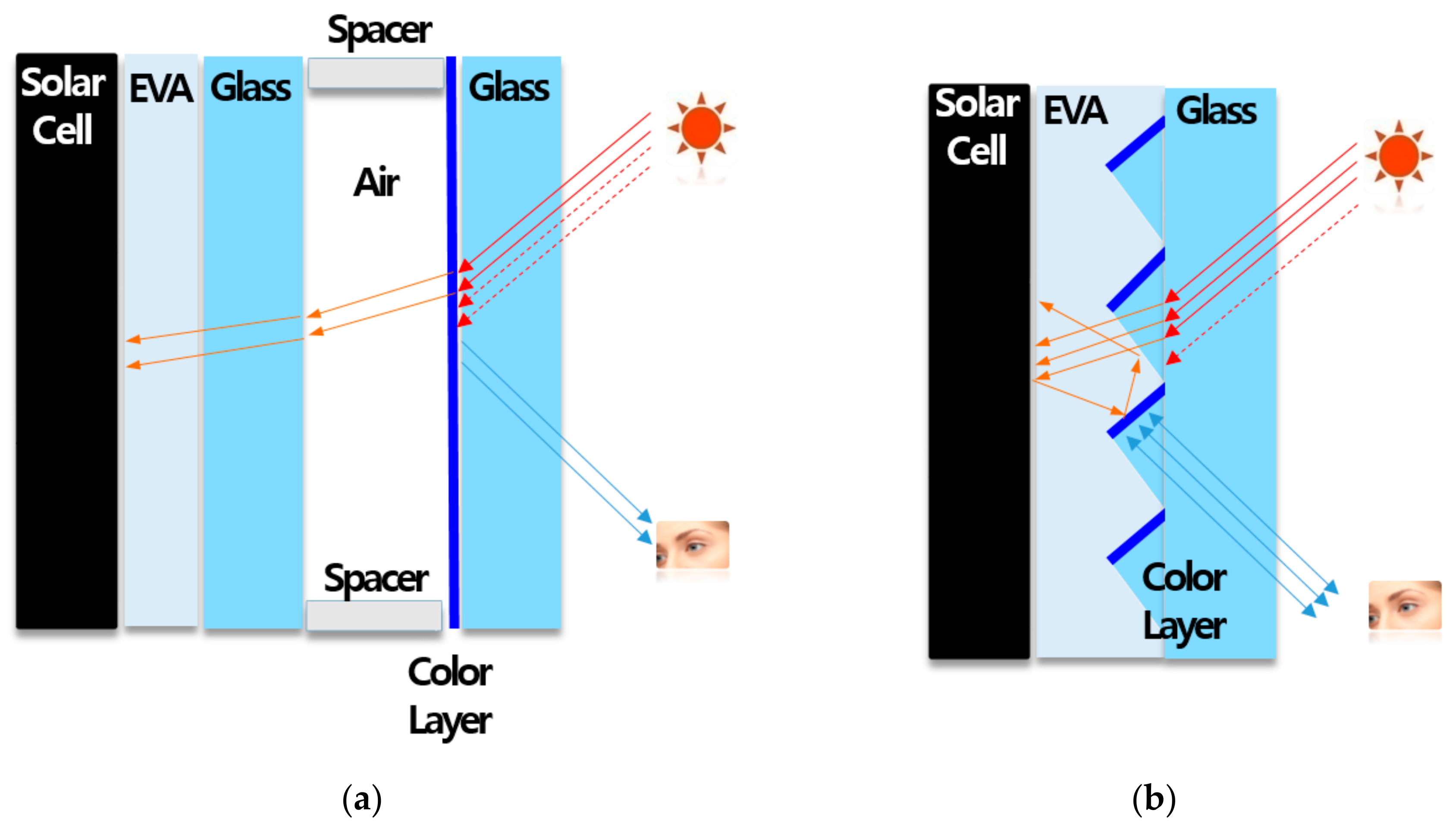
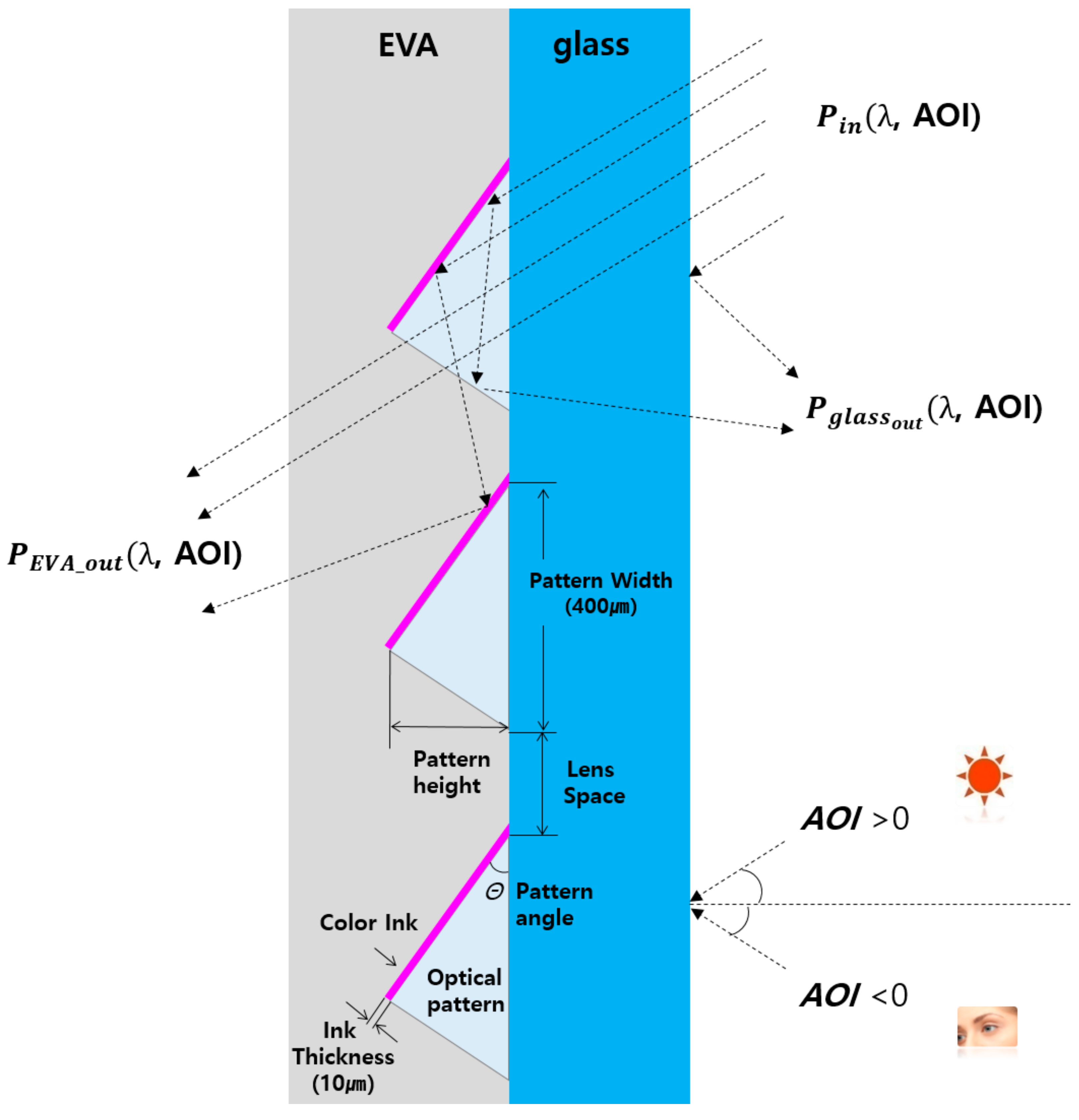
2.1. Optical Pattern Simulation

The optical pattern was optimized using simulation (LightTools, Synopsys Inc., Mountain View, CA, USA). The simulation was used to design the geometries (Figure 2) of all the optical components. Optical patterns composed of UV (ultraviolet ray) cured resin were placed on 3.2 mm-thick glass, then colored ink was selectively printed to a 10 μm thickness on the incline of the patterns. The pattern width was 400 μm. The distance between the patterns was defined as ‘lens space (S)’ and the angle between the glass surface and the ink was ‘pattern angle’ Θ, and they were varied (Table 1). An EVA (ethylene vinyl acetate) layer was deposited on top the optical patterns to a thickness of 400 μm.
In the simulations, each layer had a refractive index and absorption coefficient (Table 2) [22]. To examine the asymmetric optical effect, the angle that light incident was considered. The angle of incidence, AOI was defined as the angle between the Sun’s rays and the vertical direction of the glass surface (Figure 2). And a positive AOI means most of the Sun’s rays can reach the solar cells when the BIPV module is installed on a building as shown in Figure 1b and Figure 2. A negative AOI is the angle from which a human would observe the surface when the BIPV panels are installed on a building (i.e., from below). When AOI is negative, most of the rays are reflected because of the optical pattern and color reflection layers (Figure 2). Simulation was performed using light of wavelengths 400 ≤ λ ≤ 1200 nm at angle of incidence +80° ≤ AOI ≤ −80°. All incident light refracts at each interface and reflects at the color ink surface as described by a simple mirror model. The number of reflected and transmitted rays were counted, then the transmittance T and reflectance R were defined as:
T λ ,   AOI = P E V A _ o u t λ ,   AOI P i n λ ,   AOI
R λ ,   AOI = P g l a s s _ o u t λ ,   AOI P i n λ ,   AOI ,
where P E V A _ o u t is the number of rays that are transmitted through the EVA layer and P g l a s s _ o u t is the number of rays that are reflected by the glass layer; both P are functions of λ and AOI (Figure 2).

2.2. Additive-Manufactured Optical Pattern

To fabricate the simulated optical pattern, an AM process with UV-cured resin was used. The AM device (Figure 3) consists of a nozzle coated with a UV resin, a UV lamp curing device for immediate curing, a head composed of an ionizer, and an inkjet head guide and a computer system to designate the movement and coordinates of the head. The maximum image size that can be printed is 3200 mm × 2000 mm and consists of two heads for each color (cyan, magenta, yellow, black, white) and six heads to apply transparent UV resin varnish. The output speed was 32 m2/h for color ink and 5 m2/h for transparent optical patterns. Etching glass was used as the substrate to improve the adhesion between the glass and the UV pattern, and the UV resin was deposited to a thickness of 10 μm before the optical pattern was printed on the glass.

2.3. Module Preparation

PV modules were fabricated using the prepared colored glass with optical patterns. Each module had different pattern angle and lens space combination. It should be noted that pattern angle was controlled by varying the pattern height (Table 3). A white ink was applied when the optical pattern was formed. The modules were fabricated in the form of the glass to back sheet (G2B) module in the size of 200 mm × 200 mm. Modules were stacked in the order of 2.5 mm-thick tempered glass/EVA/c-Si/EVA/back sheet, and then lamination was performed (Figure 4a). To quantify the effect of the optical pattern, the module with a white color layer inserted between cover glass and EVA was manufactured, which is generally used when making a conventional color BIPV (Figure 4b). To normalize the power of the modules, non-colored module was manufactured. This was because measuring the photo conversion efficiency (PCE) of the module for the various AOI is not a standard procedure and PCE would be affected by not only an optical pattern but also AOI. The power of the non-colored module was set to 100% and the powers of the color modules were compared to the non-colored module. The lamination process for both modules were performed using the lamination conditions and equipment of a general crystalline PV module.

2.4. Module Electrical Properties Measurement

A special jig with a servo motor was used to control the AOI. The output power of the fabricated modules was measured according to the AOI. The maximum power, open-circuit voltage Voc, short-circuit current Isc, and Fill Factor FF were measured at −60° ≤ AOI ≤ +60° for the additive manufactured color modules, conventional color module and a reference (non-colored) module.

3. Results and Discussion

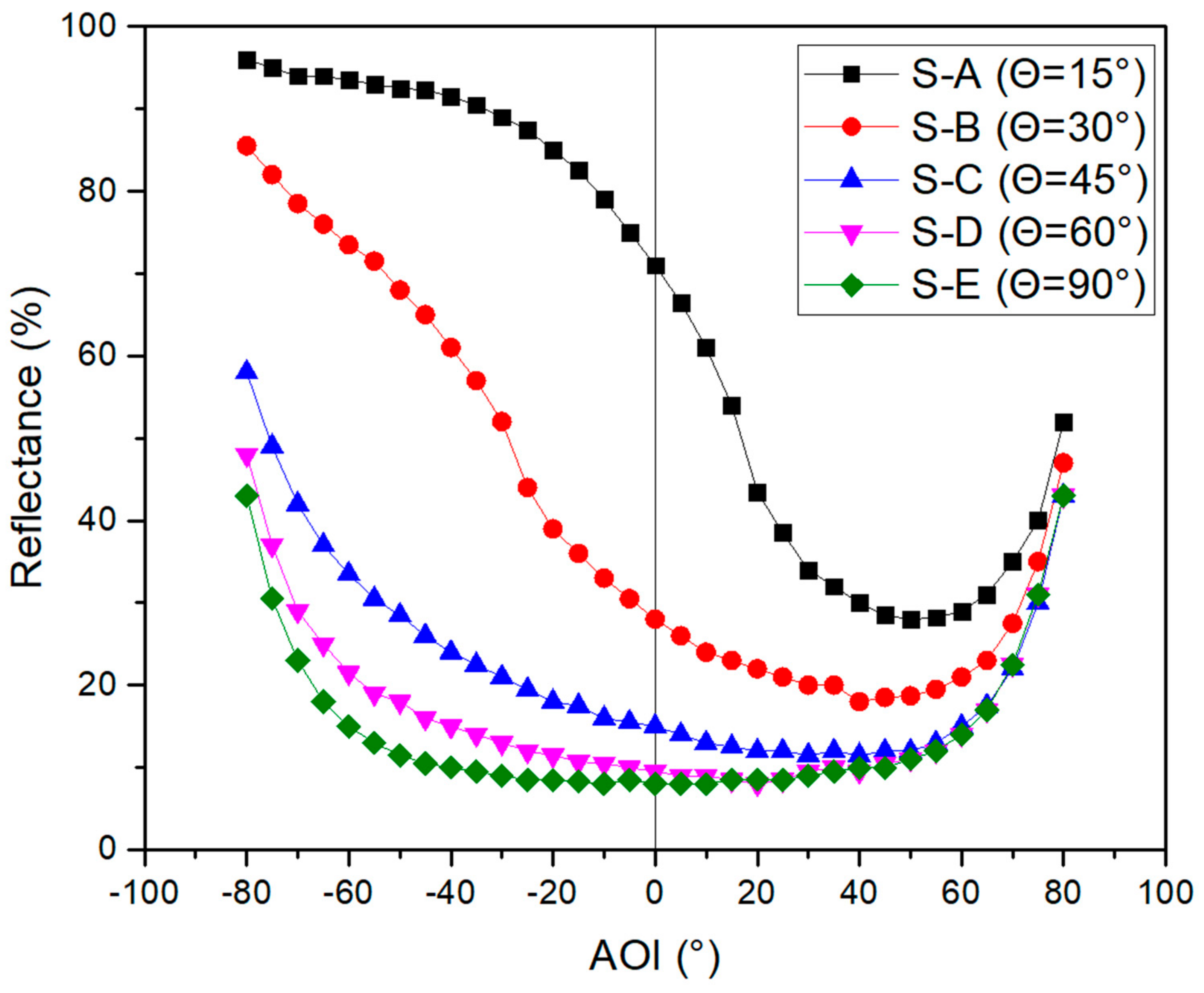
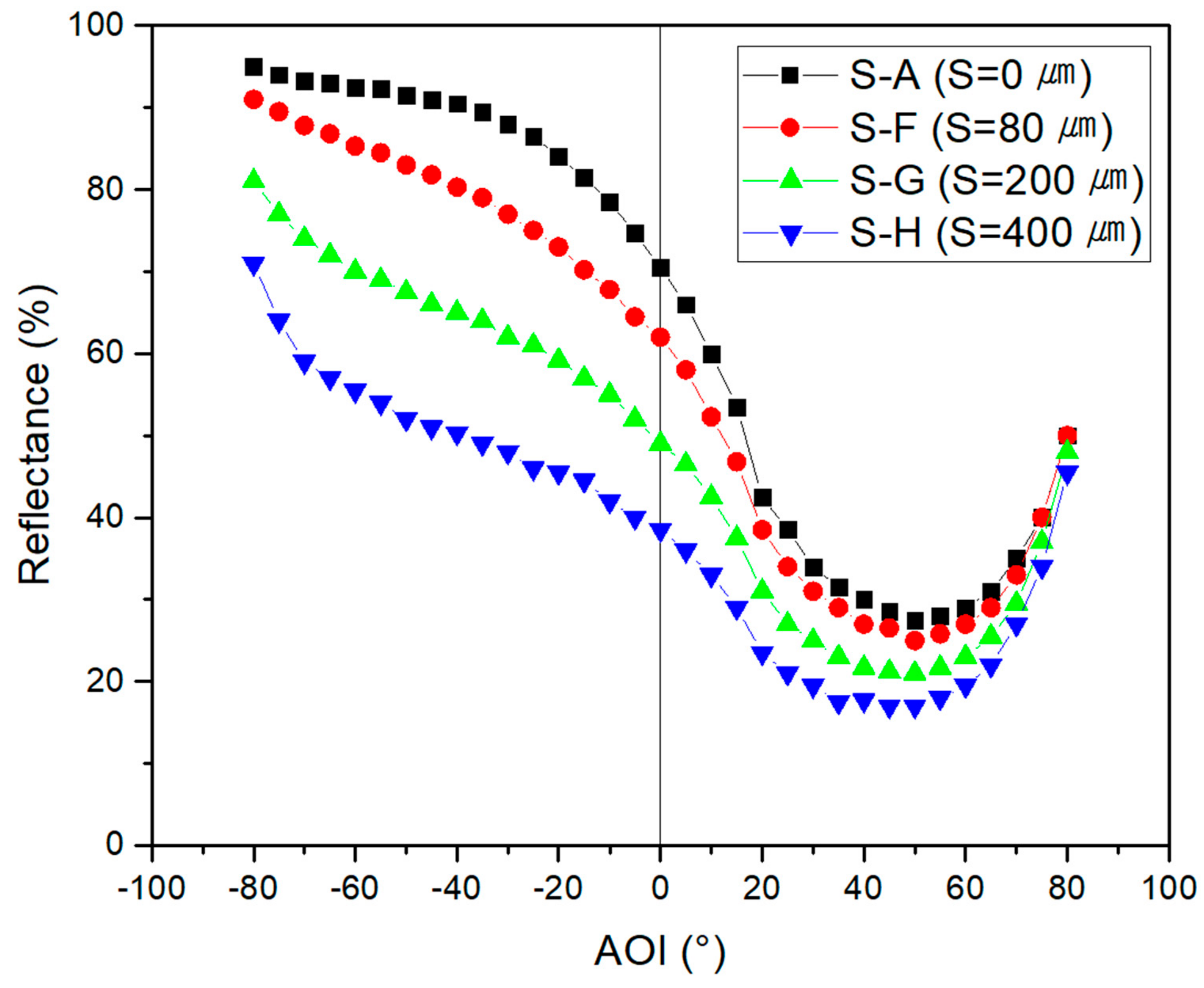
3.1. Optical Simulation

In the simulation model S-A, the optical pattern had Θ = 15° and lens space S = 0. From S-A to S-E, Θ increased from 15° to 90°. R was calculated for each case (Figure 5). According to the simulation, in S-A, the reflectance was >80% at AOI < −40°, so most of the light would be reflected. At AOI > +40°, the reflectance dropped to 40% and sunlight is expected to enter and reach the solar cells. Pohang, where this research was conducted, has a latitude of 36°; the lowest elevation of the sun is 30° at noon during the winter solstice and the highest elevation is 76° during the summer solstice [23].
R decreased and T increased as Θ increased, and the asymmetry according to the AOI was lost. To quantify the optically asymmetry, an asymmetric factor is defined as
A s = V A O I = 40 V A O I = + 40 V A O I = + 40
where V A O I = 40 means a value at AOI = −40° and V A O I = + 40 means a value at AOI = +40°; both were normalized by dividing by the value at AOI = 0°. Here, the value can be R or the output power ratio of the BIPV module. As of the simulated model ranged from 0 to 1.54 (Table 4). It was low (≤0.58) in simulations S-D and S-E; this result means that the optical pattern lost its function. Therefore, to ensure the asymmetric reflectance for BIPV application, Θ should not exceed 45°.
S-A and from S-F to S-G, S (lens space) increased from 0 to 400 μm. R was calculated for each case (Figure 6). As S increased, R decreased, because a large S permits the passage of light through the optical pattern, with no chance to reflect. As did not drop dramatically (Table 4). However, R = 50% at AOI = −40° for when S = 400 μm, so it is too transparent to hide the solar cells under the optical pattern. The wider lens space makes the color darker in terms of brightness, and the resolution lower in terms of image quality [24].

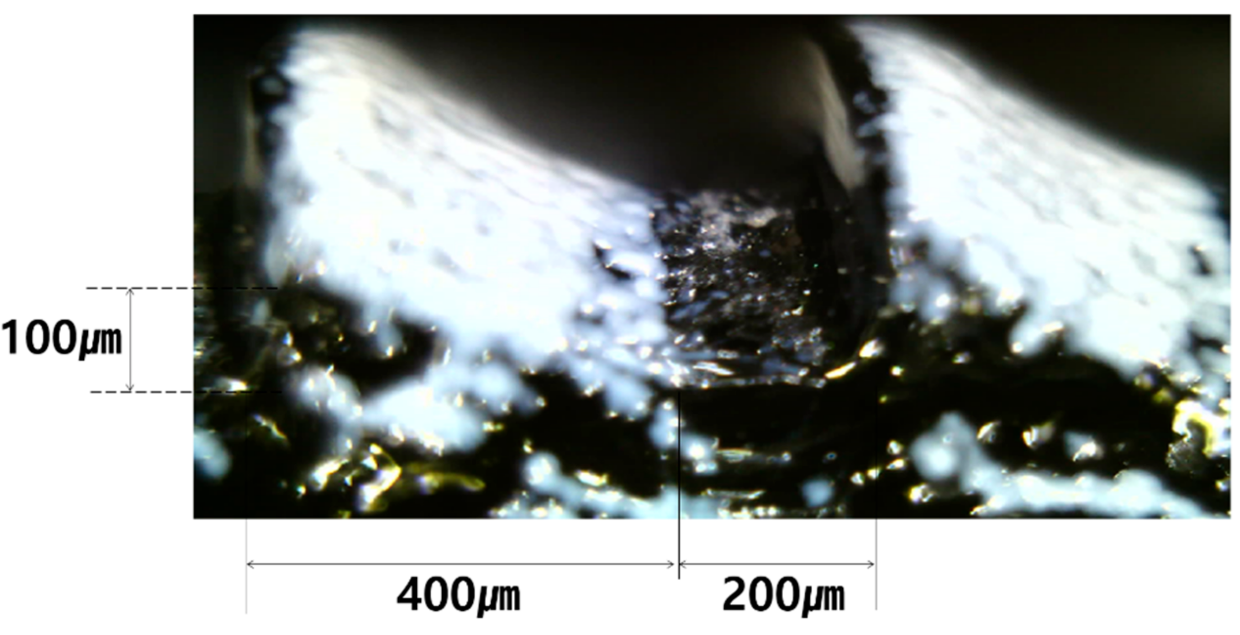
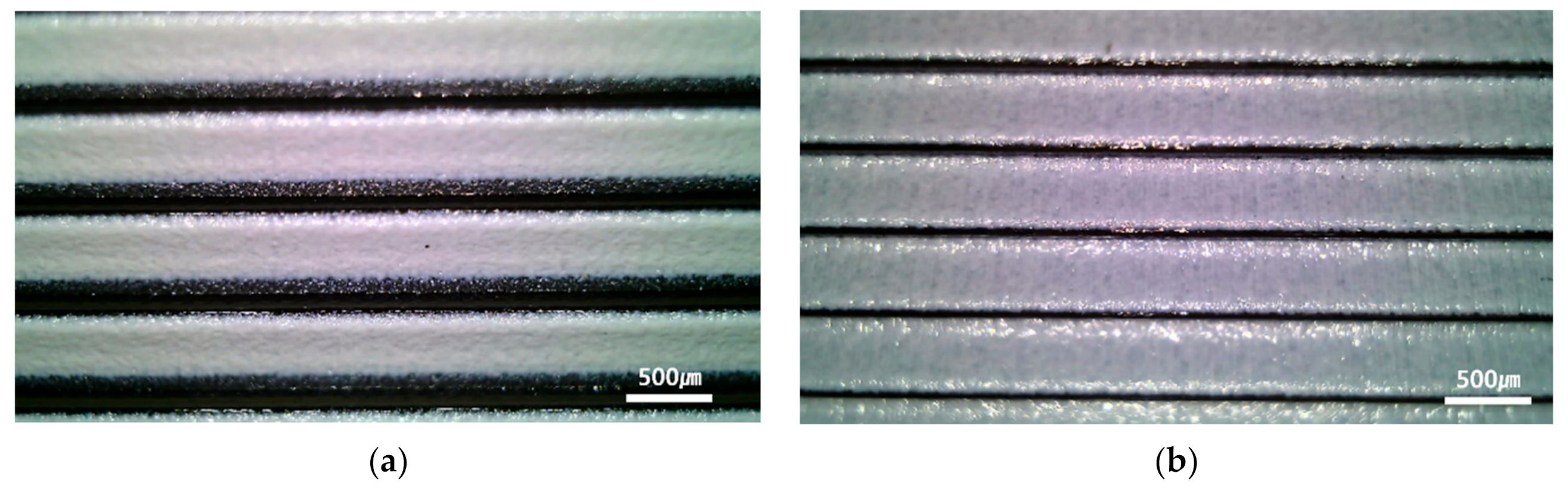
3.2. Optical Pattern Formation

Considering the simulation results, a basic optical pattern (M-A) was fabricated using AM. The pattern had a pattern width = 400 μm, S = 200 μm, and Θ = 15° (pattern height = 100 μm) (Figure 7). M-A corresponds to the simulation model S-G. M-A had a different appearance from AOI = +40° than from AOI = −40° because of the different reflectance (Figure 8).

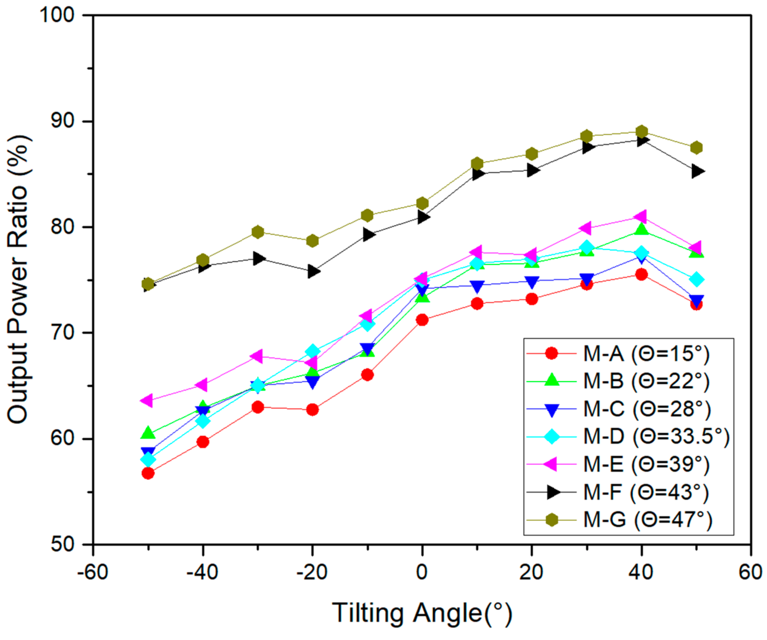
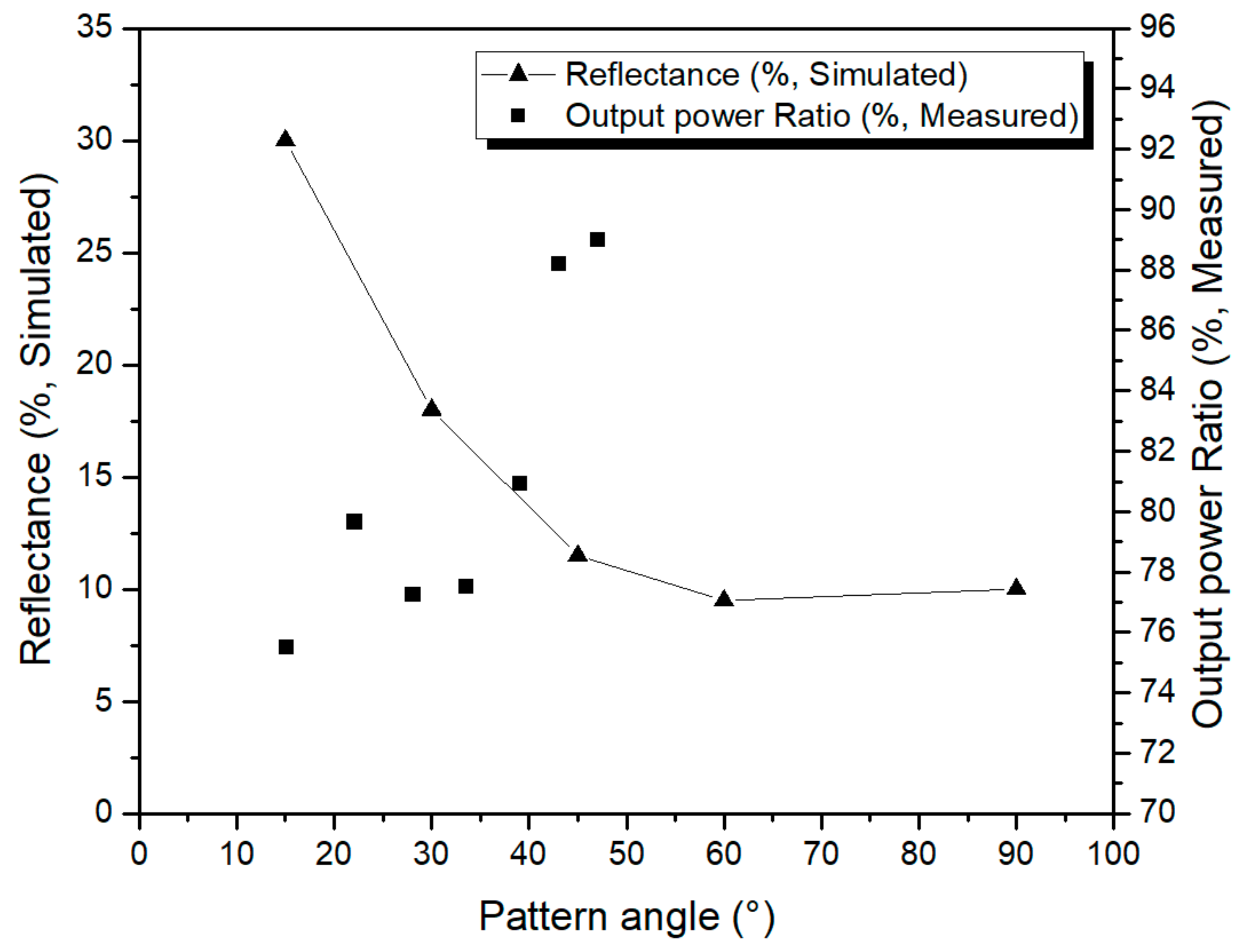
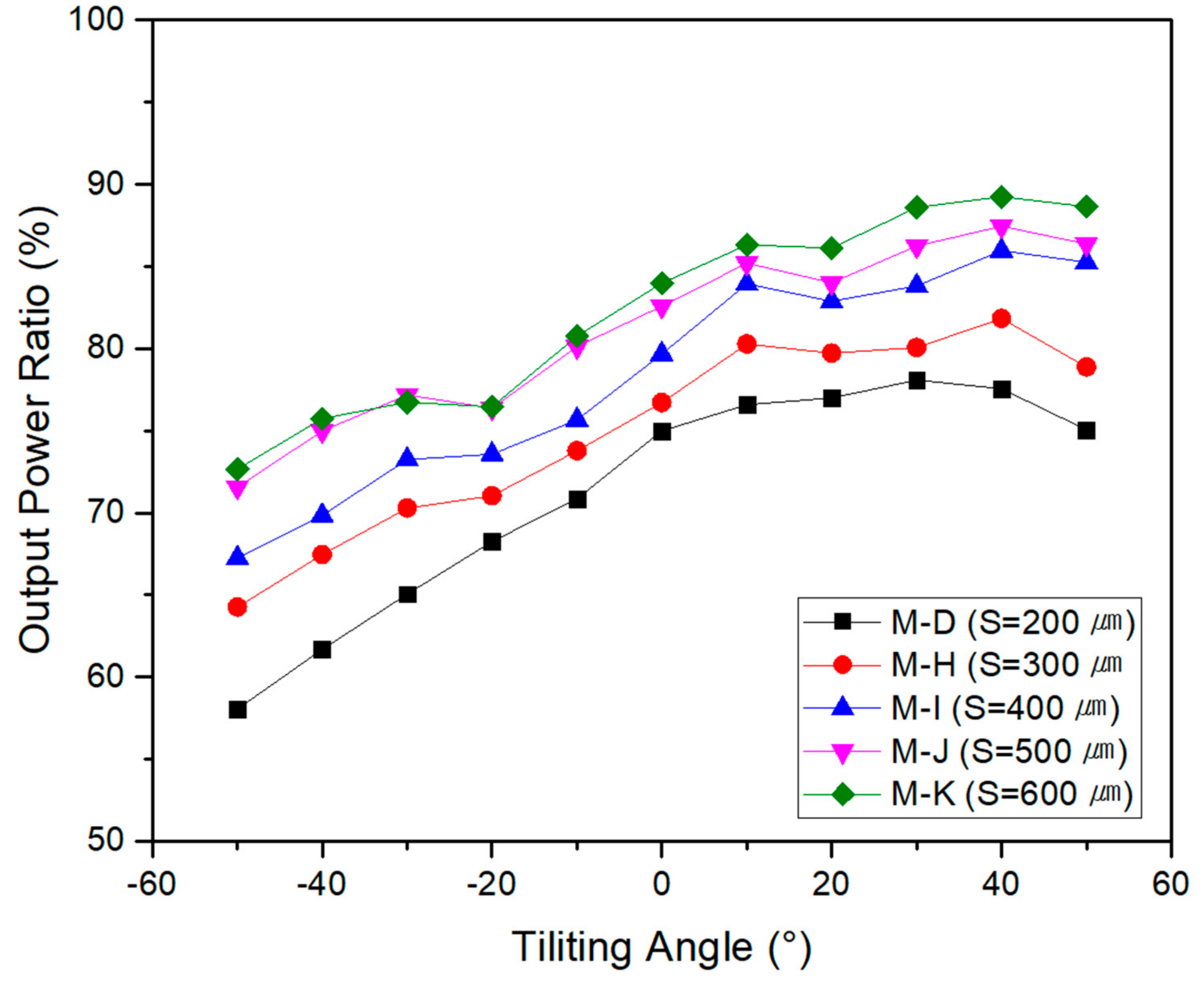
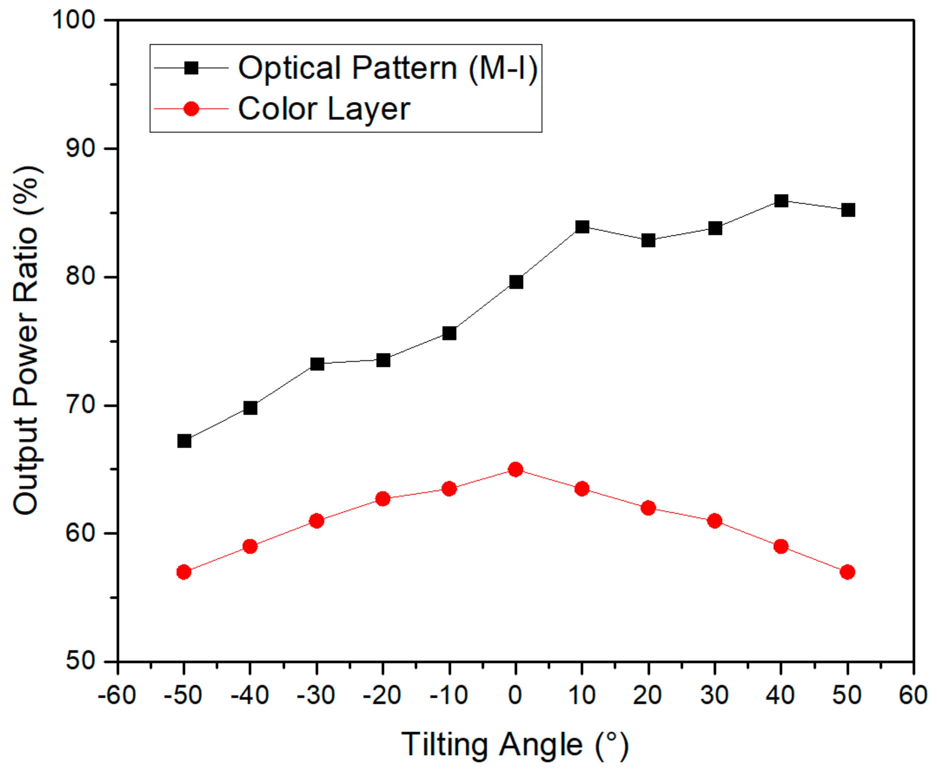
3.3. Output Power According to Incident Angle of Light

To control Θ, an optical pattern was created by changing the pattern height from 100 μm to 400 μm; i.e., seven types of modules (M-A ~ M-G) were manufactured (Table 3). To normalize according to Θ, as mentioned above, the power of the non-colored module was set to 100% and the power of the color module was compared to the non-colored module (Figure 9). The maximum output power ratio was obtained by M-G which had Θ = 47° (so that pattern height = 400 μm) was 89% at AOI = +40° (average 88% over all AOI). The output power is remarkable because the power of the color modules previously reported has shown 60% of the non-colored module [17].
The maximum power of the modules increased as Θ was increased. It is consistent with the simulation result. For the AOI = +40°, the simulated reflectance and output power ratio are compared as a function of Θ (Figure 10). The lower reflectance yields the higher output power of a module because more lights would reach to the solar cells. However, asymmetric factors of M-F and M-G were dropped compared to the other modules (Table 5). The asymmetric factor represents the functionality of the optical pattern. Low asymmetric factor means that the optical pattern lost its function and light can reach the solar cells no matter what the AOI is. Then the black solar cells can be seen and the optical pattern is meaningless. The asymmetric factor for the M-F is 0.147 and it is 30% lower than that of M-E. This means the optical pattern of M-E can reflect incident light 30% more efficiently than M-F and the color of M-E is more vivid. Considering the aesthetics, the maximum Θ was determined to by <39°, which corresponds to pattern height = 300 μm (M-E). The maximum output power ratio of M-E was 80.1% at AOI = 40° (average 79% at +20° ≤ AOI ≤ +50°).
The output power was measured by manufacturing the module while fixing pattern height to 250 μm and increasing the lens space, S from 200 μm to 600 μm (M-D, M-H to M-K). At S = 600 μm, the maximum output power ratio was 89%, and the average output ratio was 88% (Figure 11). It is obvious that the output power ratio increased as S increased because a large S permits the passage of light through the optical pattern, with no chance to reflect it. The simulation also predicted a decreasing reflectance and increasing output power ratio for the large S at AOI = +40 (Figure 12).
However, for S > 400 μm, the coverage of optical pattern is less than 50% because the pattern width is 400 μm. As Reddy reported, the lower the coverage, the poorer the visual quality because the unprinted area is almost black since there is no ink to reflect. That is, a large lens space creates the darker color in terms of brightness, and lowers the resolution in terms of image quality [24]. In term of the asymmetric factor, M-J and M-K showed relatively low values compared to the other modules (Table 5). It could be possible that over half of the total incident light would not be affected by the optical pattern for S > 400 μm since the pattern width is 400 μm. Considering the aesthetics, the optimal S ≈ 400 μm, at which the average output power ratio of 85% was relatively high.
The output power ratios of the color module with or without the optical pattern were compared (Figure 13). The color module without the optical pattern (Figure 4b) gave the maximum output power at Θ = 0° and had a symmetric output power response to Θ. However, the proposed color modules with optical patterns (M-I) had up to 30% higher power output than the color module without the optical pattern at +20 ≤ tilting angle ≤ +60°, which means that the color module with an optical pattern is effective when applied on a building wall.

4. Conclusions

A PV module with optical patterns optimized for BIPV applications was manufactured. The size and shape of the optical pattern were optimized using simulation. Optical patterns with different pattern angles Θ and lens spaces S were implemented on glass, by using additive manufacturing using UV resins. Color modules that had a size of 200 mm × 200 mm were manufactured using glass on which the optical pattern was implemented, and the maximum output power was measured. As Θ and S increased, the power of the module increased, but aesthetic considerations required Θ ≤ 39° and S ≤ 400 μm. When applied to a BIPV module, the optical pattern using additive manufacturing can be variously modified according to the conditions required for a BIPV, such as reducing Θ to 15° and S to 200 μm or less, for the aesthetics. When power-generation characteristics are more crucial than aesthetics, then Θ can be > 30° and S can be > 400 μm. In this paper, the asymmetric factor was the only factor considered for the aesthetics and it was still not sufficient to quantify the visual quality. However, other factors that have aesthetic effects should be considered such as the brightness and resolution of the color and image of the BIPV.

Author Contributions

Conceptualization, methodology, writing—original draft preparation, Y.-S.K.; data curation, resources, writing—review and editing, A.-R.K.; funding acquisition, S.-J.T. All authors have read and agreed to the published version of the manuscript.

Funding

This work was supported by the Korea Institute of Energy Technology Evaluation and Planning(KETEP) and the Ministry of Trade, Industry & Energy(MOTIE) of the Republic of Korea (No. 20203040010330).

Institutional Review Board Statement

Not applicable.

Informed Consent Statement

Not applicable.

Data Availability Statement

The data can be accessed upon request from any of the authors.

Conflicts of Interest

The authors have no conflict of interest.

References

  1. Hamilton, I.; Kennard, H.; Rapf, O.; Kockat, J.; Zuhaib, S.; Abergel, T.; Oppermann, M.; Otto, M.; Loran, S.; Steurer, N.; et al. 2020 Global Status Report for Buildings and Construction: Towards a Zero-Emission; United Nations Environment Programme, Efficient and Resilient Buildings and Construction Sector: Nairobi, Kenya, 2020. [Google Scholar]
  2. Net Zero Tracker. Net Zero Numbers. Available online: http://netzerotracker.net/ (accessed on 23 November 2021).
  3. Marszal, A.J.; Heiselberg, P.; Bourrelle, J.S.; Musall, E.; Voss, K.; Sartori, I.; Napolitano, A. Zero Energy Building—A review of definition and calculation methodologies. Energy Build. 2011, 43, 917–919. [Google Scholar] [CrossRef]
  4. World Energy Outlook 2020-Analysis—IEA. Available online: https://www.iea.org/reports/world-energy-outlook-2020 (accessed on 25 December 2021).
  5. Pelle, M.; Lucchi, E.; Maturi, L.; Astigarraga, A.; Causone, F. Coloured BIPV technologies: Methodological and experimental assessment for architecturally sensitive areas. Energies 2020, 13, 4506. [Google Scholar] [CrossRef]
  6. Berger, K.; Cueli, A.B.; Boddaert, S.; Buono, M.D.; Delisle, V.; Fedorova, A.; Frontini, F.; Ishii, H.; Kapsis, C.; Kim, J.-T.; et al. International Definition of “BIPV”; IEA: Paris, France, 2018; ISBN 978-3-906042-73-26. [Google Scholar]
  7. Shukla, A.K.; Sudhakar, K.; Baredar, P. Recent advancement in BIPV product technologies: A review. Energy Build. 2017, 140, 188–195. [Google Scholar] [CrossRef]
  8. Bao, Q.; Honda, T.; Ferik, S.; Shaukat, M.M.; Yang, M.C. Understanding the role of visual appeal in consumer preference for residential solar panels. Renew. Energy 2017, 113, 1569–1579. [Google Scholar] [CrossRef] [Green Version]
  9. Zhang, T.; Wnag, M.; Yang, H. A Review of the Energy Performance and Life-Cycle Assessment of Building-Integrated Photovoltaic. Energies 2018, 11, 3157. [Google Scholar] [CrossRef] [Green Version]
  10. Durante, A.; Lucchi, E.; Maturi, L. Building integrated Photovoltaic in heritage contexts award: An overview of best practices in Italy and Switzerland. IOP Conf. Ser. Earth Environ. Sci. 2021, 863, 012018. [Google Scholar] [CrossRef]
  11. Liu, B.; Duan, S.; Cai, T. Photovoltaic DC-Building-Module-Based BIPV System-Concept and Design Condideration. IEEE Trans. Power Electron. 2011, 26, 1418–1429. [Google Scholar] [CrossRef]
  12. Biyik, E.; Araz, M.; Hepbasli, A.; Shahrestani, M.; Yao, R.; Shao, L.; Essah, E.; Oliveira, A.C.; Caño, T.; Rico, E.; et al. A key review of building integrated photovoltaic (BIPV) systems. Eng. Sci. Technol. Int. J. 2017, 20, 833–858. [Google Scholar] [CrossRef]
  13. Ravyts, S.; Vecchia, M.D.; Broeck, G.V.; Driesen, J. Review on Building-Integrated Photovoltaics Electrical System Requirements and Mod-ule-Integrated Converter Recommendations. Energies 2019, 12, 1532. [Google Scholar] [CrossRef] [Green Version]
  14. Lee, H.; Song, H.-J. Current status and perspective of colored photovoltaic modules. WIREs Energy Environ. 2021, 10, 403. [Google Scholar] [CrossRef]
  15. Hille, S.L.; Curtius, H.C.; Wüstenhagen, R. Red is the new blue—The role of color, building integration and country-of-origin in homeowners’ preferences for residential photovoltaics. Energy Build. 2018, 162, 21–31. [Google Scholar] [CrossRef]
  16. Ghosh, A. Potential of building integrated and attached/applied photovoltaic(BIPV/BAPV) for adaptive less energy-hungry building’s skin: A comprehensive review. J. Clean. Prod. 2020, 276, 123343. [Google Scholar] [CrossRef]
  17. Eder, G.; Peharz, G.; Trattnig, R.; Bonomo, P.; Saretta, E.; Frontini, F.; Lopez, C.S.; Wilson, H.R.; Eisenlohr, J.; Chivelet, N.M.; et al. COLOURED BIPV-Market, Research and Development; IEA: Paris, France, 2019. [Google Scholar]
  18. Jolissaint, N.; Hanbali, R.; Hadorn, J.-C.; Schüler, A. Colored solar facades for building. Energy Procedia 2017, 122, 175–180. [Google Scholar] [CrossRef]
  19. Eder, G.C.; Knöbl, K.; Maul, L.; Aichinger, M.; Peharz, G.; Nemitz, W.; Berge, K.A. Designed BIPV-Elements with Printed Front-Glass: Simulation and Experimental Evaluation of the Effect of Printing on the Electrical Performance. In Proceedings of the 33th PV-SEC, Amsterdam, The Netherlands, 25–29 September 2017; pp. 1295–1303. [Google Scholar]
  20. Kameleon Solar. Available online: Kameleonsolar.com/products/colorblast/ (accessed on 23 November 2021).
  21. Reese, M.O.; Glynn, S.; Kempe, M.D.; McGott, D.L.; Dabney, M.S.; Barnes, T.M.; Booth, S.; Feldman, D.; Haegel, N.M. Increasing markets and decreasing package weight for high-specific-power photovoltaics. Nat. Energy 2018, 3, 1002–1012. [Google Scholar] [CrossRef]
  22. PVLighthouse. Refractive Index Library. Available online: www.pvlighthouse.com/au/ko/refractive-index-library/ (accessed on 30 November 2021).
  23. Solar Geometry Calculator. Available online: gml.noaa.gov/grad/antuv/SolarCalc.jsp?mu=on&sza=on&el=on&az=on/ (accessed on 30 November 2021).
  24. Reddy, C.R. Performance of Ceramic Ink Printed Colour Photovoltaic Technology. Master’s Thesis, Delft University of Technology, Delft, The Netherlands, 2018. [Google Scholar]
Figure 1. Schematic diagram of color building-integrated photovoltaic (BIPV) module structure (a) conventional color BIPV using color glass on the normal photovoltaic (PV) module (b) suggested structure using optical patterns.
Energies 15 01288 g001
Figure 2. Geometries of optical pattern used in simulation.
Energies 15 01288 g002
Figure 3. Diagram of inkjet printing system.
Energies 15 01288 g003
Figure 4. Schematic diagram of fabricated color BIPV modules (a) module with pattern applied using additive manufacturing (AM) (b) module with continuous color layer.
Energies 15 01288 g004
Figure 5. Simulated reflectance according to the pattern angle.
Energies 15 01288 g005
Figure 6. Simulated reflectance according to the lens space (S).
Energies 15 01288 g006
Figure 7. Optical microscope image of AM processed optical patterns.
Energies 15 01288 g007
Figure 8. Optical microscope image of optical pattern printed using AM printer (a) at angle of incidence (AOI) = +40° (b) at AOI = −40°.
Energies 15 01288 g008
Figure 9. Output power ratio for the different pattern angles (Θ). The higher the pattern angle (Θ), the higher the output power ratio.
Energies 15 01288 g009
Figure 10. Output power ratio for the different pattern angles (Θ) was compared to the simulated reflectance.
Energies 15 01288 g010
Figure 11. Output power ratio according to lens space (S) from 200 to 600 μm.
Energies 15 01288 g011
Figure 12. Output power ratio for the different lens space (S) was compared to the simulated reflectance.
Energies 15 01288 g012
Figure 13. Output power ratio of 3D printing modules compared to the conventional color layer module.
Energies 15 01288 g013
Table 1. Simulation variations for pattern angle and lens space.
Simulation ModelPattern Angle, θ (°)Lens Space, S (μm)
S-A150
S-B300
S-C450
S-D600
S-E900
S-F1580
S-G15200
S-H15400
Table 2. Refractive index of layers used for simulation.
Layer450 nm550 nm650 nm
Refractive indexGlass1.5021.4951.491
UV resin1.5091.5041.499
EVA1.5001.4951.489
Absorption
Coefficient
(/cm)
Glass2.425 × 1031.284 × 1031.735 × 103
UV resin4.854 × 1033.771 × 1034.219 × 103
EVA9.682 × 1035.372 × 1033.708 × 103
Table 3. Experimental variation for pattern angle and lens space. Pattern angle is controlled by varying pattern height.
Module NameLens Space, S
(μm)
Pattern Height (μm)Pattern Angle, θ (°)
M-A20010015
M-B20015022
M-C20020028
M-D20025033.5
M-E20030039
M-F20035043
M-G20040047
M-H30025033.5
M-I40025033.5
M-J50025033.5
M-K60025033.5
Table 4. Asymmetric factors of simulated models.
Simulation ModelAsymmetric Factor (As)
S-A0.87
S-B1.54
S-C0.83
S-D0.58
S-E0.0
S-F0.86
S-G0.88
S-H0.85
Table 5. Asymmetric factors of fabricated modules.
Fabricated ModuleAsymmetric Factor (As)
M-A0.222
M-B0.229
M-C0.197
M-D0.212
M-E0.211
M-F0.147
M-G0.147
M-H0.187
M-I0.202
M-J0.151
M-K0.161
Publisher’s Note: MDPI stays neutral with regard to jurisdictional claims in published maps and institutional affiliations.

