Article

Fault-Tolerant Fuzzy Logic Control of a 6-Phase Axial Flux Permanent-Magnet Synchronous Generator

Laboratory of Innovative Technologies (LTI), Department of Electrical Engineering, University of Picardie Jules Verne, 80025 Amiens, France
*
Author to whom correspondence should be addressed.
Energies 2022, 15(4), 1301; https://doi.org/10.3390/en15041301
Submission received: 7 January 2022 / Revised: 6 February 2022 / Accepted: 7 February 2022 / Published: 11 February 2022

Abstract

:
The objective of this paper is to propose the real-time implementation of a fault-tolerant strategy based on fuzzy logic controller (FLC) for a Six-Phase Axial Flux Permanent Magnet Synchronous Machine (6P-AFPMSM) for electrical energy production. This type of machine, suitable for high-power applications, is highly affected by the harmonics of the inductances and the electromotive force (emf) compared to the classical three-phase radial flux machine, which will influence the controller parameters of the machine. The proposed control strategy based on FLC is independent of the system model and guarantees the robustness of the process against disturbances and parameter variations of the model. An experimental comparison between FLC and a classical PI controller confirms the efficiency and the robustness of the proposed controller in healthy and faulty conditions with one open phase.

1. Introduction

Wind energy, which becomes the most important source of renewable energy production with low CO2 emission, is growing year-on-year around the world. The year 2020 was the best one yet, with 93 GW of a new capacity installed despite the impacts of COVID-19, making a total of 743 GW of wind power capacity worldwide. In spite of this fact, we need to increase to around 280 GW per year after 2030 to reach carbon neutrality objectives [1].
In the future, most wind farms will be moved offshore, taking advantage of stronger marine winds. This large request of the wind markets will require a suitable reliability of the system and especially an increased availability of the energy production with a minimized maintenance.
In this way, the axial-field electrical machines with permanent magnet excitation are one of the best candidates for high-power applications, especially for wind power generators. The main advantages of this machine topology over conventional radial flux machine are the compactness, the robustness and the high torque-to-weight ratio [2,3,4,5,6,7].
Although they are recognized for high-power applications, whether in motor or generator mode, the classical three-phase structure induces many problems of safety, reliability and feasibility. Indeed, the loss of one phase on the machine or of one converter leg leads to an overload in the two other phases, which presents a major unbalance in the machine and causes a significant downtime of the energy production and a high maintenance cost.
One solution to increase the efficiency and reliability of the generator is to use a multiphase machine with symmetrical [8,9,10,11,12,13] or asymmetrical windings [14,15,16,17,18].
Indeed, multiplying the number of stator phases improves the torque quality and increases the reliability since the energy production is maintained in faulty modes since three phases remain. However, despite the preservation of energy production in faulty mode with multi-phase machines, power ripples subsist in this case due to the unbalance structure between the stator and the rotor. Therefore, to limit this effect, the PI controllers usually used in Field-Oriented Control (FOC) are no more suitable and have to be substituted by an advanced control algorithm to ensure the robustness of the process in the faulty modes (loss of phases or converter legs).
In this way, a robust, fault-tolerant current control of a Six-Phase Permanent Magnet Synchronous Machine (6P-PMSM) for wind energy conversion systems (WECS) is proposed using Fuzzy Logic Control (FLC) that substitutes PI regulation in the FOC strategy. Definitely, FLC is well-known for its capacities to be a robust and adequate controller for non-linear processes subjected to large and unknown variations in the model parameters as our 6P-PMSM in faulty modes.
This control strategy that has been already applied successfully with the exact same structure on a radial 6-phase induction generator [19,20] is now tested in this paper on a wind turbine prototype based on a 24 kW 6P-AFPMSM built in our laboratory with a high number of poles.
An experimental comparison between the proposed FLC and the classical PI controller has been realized. The parameters of the latter have been computed by using the pole placement approach detailed in [21] and are given in the Appendix C.
The novelty and the main advantage of the proposed approach compared to the PI control stay in the natural fault tolerance capacities of the FLC. Indeed, the same parameters for the FLC are kept in healthy and faulty conditions, no phase-fault detection algorithm is required and, furthermore, the same generated power as in the healthy mode is maintained in faulty mode with less ripples than with the conventional PI controller.
The paper is organized as follows. Section 2 is dedicated to the topology and model of the 6P-AFPMSM generator using FOC, while Section 3 depicts the proposed FLC structure. The test bed is introduced in Section 4, and the experimental results are presented in healthy and faulty conditions. Then, Section 5 and Section 6 are devoted to discussions and conclusions, respectively.

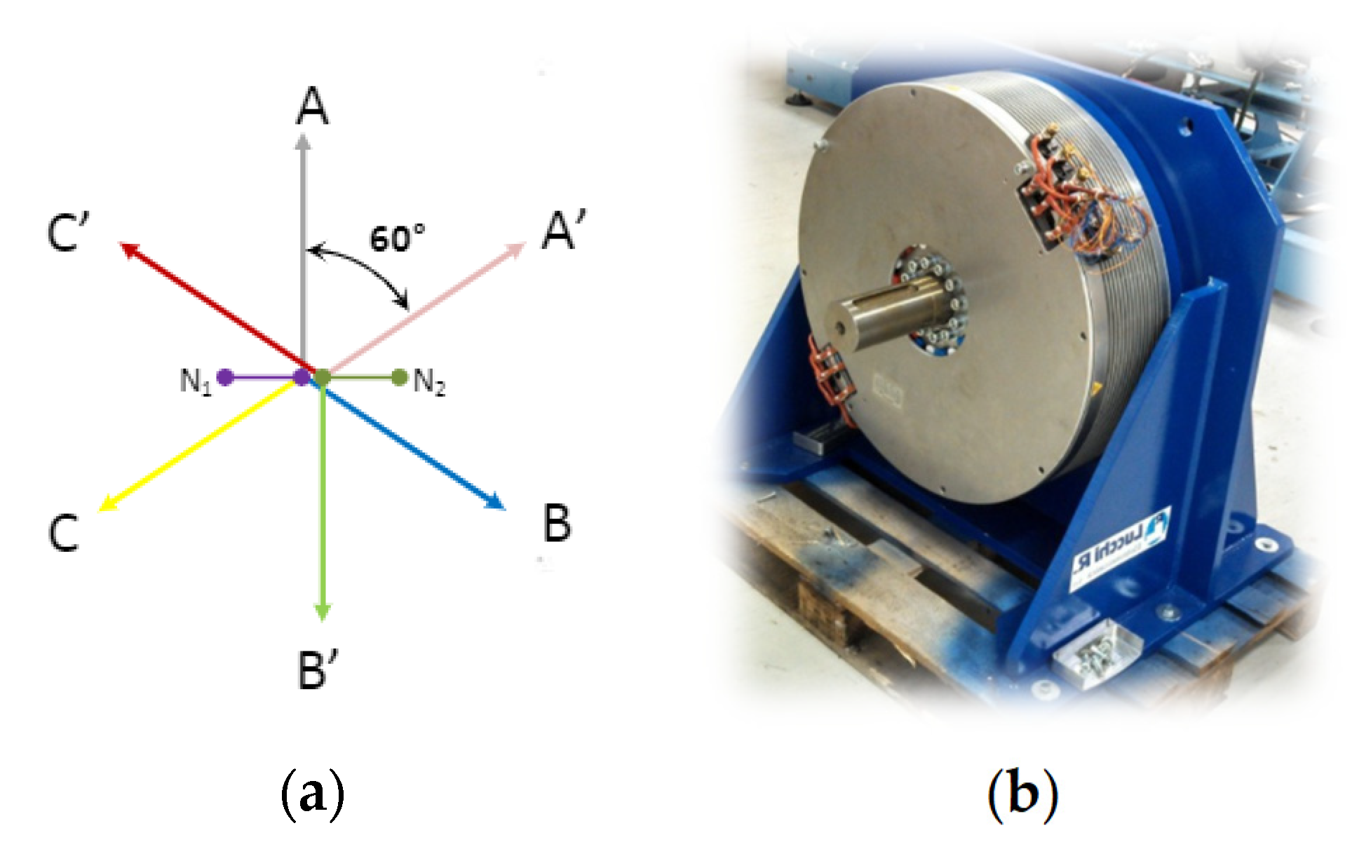
2. Topology and Model of 6P-AFPMSM

6P-AFPMSM machines can be designed as single-sided or double-sided. Two possible configurations can be adopted with double-sided machines, either the external stator or the external rotor configurations [22,23,24]. In this paper, we will focus on the double-sided 6P-AFPMSM prototype with internal single-stator and external double-rotor structure as shown in the Appendix D. The parameters of this machine are given in the Appendix A. In the literature, this proposed one is called a TORUS machine, carrying a total of 32 permanent magnets based on NdFeB (Neodymium Iron Boron) on the rotor discs and six-phase windings that are symmetrically mounted in the slots on the stator yoke as shown in Figure 1. NdFeB is known for its high values of the flux density in the air gap and also a good efficiency.

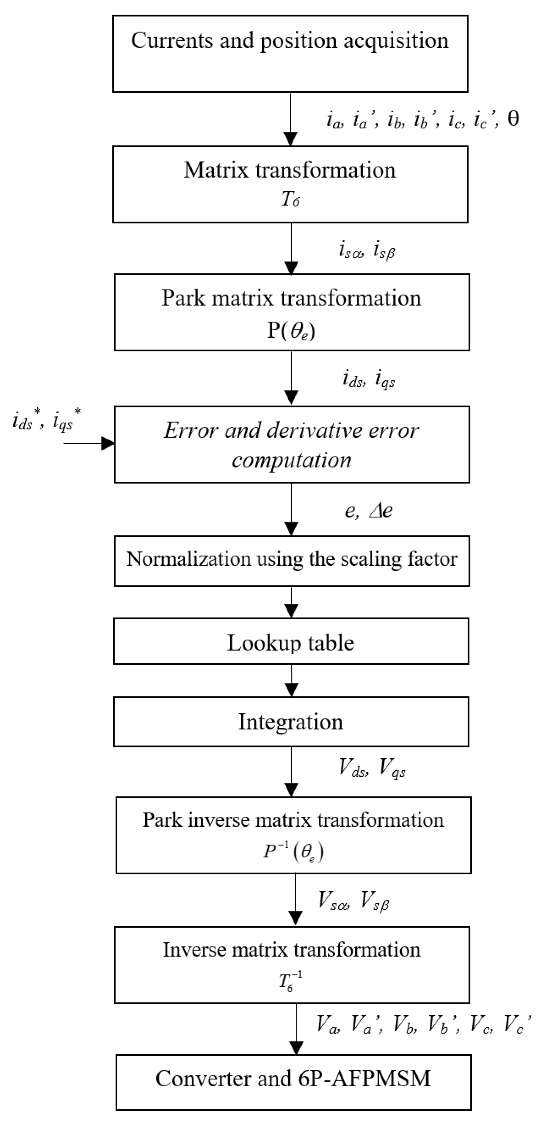
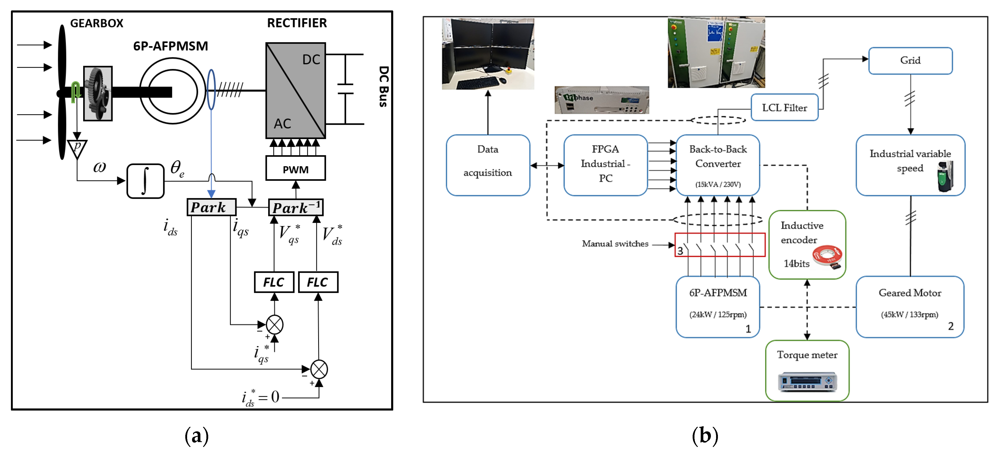
2.1. Field Oriented Control

Vector control or FOC technique saw its beginning in the years 1968–1970 by Hasse and Blaschke. The main advantage of this technique is to control the magnetic flux and the torque of the AC machines separately [25]. In this paper, we will associate this strategy with FLC in order to control the inner loops of the 6P-AFPMSM, which represent the direct and quadrature components of the stator currents.
The voltage (1) and flux (2) equations of the 6P-AFPMSM in natural coordinate system can be written in a compact matrix:
[ V s ] = [ R s ] [ i s ] + [ d φ s d t ]
[ φ s ] = [ L s ] [ i s ] + [ φ m ]
where:
  • [ V s ] are the stator terminal voltages to neutral voltage [ V s a V s a V s b V s b V s c V s c ] T ;
  • [ i s ] are the stator phase currents [ i s a i s a i s b i s b i s c i s c ] T ;
  • [ R s ] are the stator phase winding resistances with [ R s ] = d i a g 6 ( R s ) ;
  • [ φ s ] are the stator winding fluxes linkages [ φ s a φ s a φ s b φ s b φ s c φ s c ] T ;
  • [ φ m ] are the permanent magnet fluxes [ φ m a φ m a φ m b φ m b φ m c φ m c ] T ;
  • [ L s ] are the stator inductance windings:
    [ L s ] = [ L a a L a b L a c L a a L a b L a c L b a L b b L b c L b a L b b L b c L c a L c b L c c L c a L c b L c c L a a L a b L a c L a a L a b L a c L b a L b b L b c L b a L b b L b c L c a L c b L c c L c a L c b L c c ]
    where L a a , L b b , L c c , L a a , L b b , and L c c are the self-inductance of the stator windings, and the others represent the mutual inductances of the stator windings.
Our choice is based on the method of decoupling vector space by ensuring the conservation of the total powers under the transformation [26]. This is conducted by applying the [T6] matrix (3) to the voltages and currents as shown in (4) and (5):
T 6 = 1 3 [ cos ( θ 1 ) cos ( θ 2 ) cos ( θ 3 ) cos ( θ 4 ) cos ( θ 5 ) cos ( θ 6 ) sin ( θ 1 ) sin ( θ 2 ) sin ( θ 3 ) sin ( θ 4 ) sin ( θ 5 ) sin ( θ 6 ) cos ( 2 θ 1 ) cos ( 2 θ 2 ) cos ( 2 θ 3 ) cos ( 2 θ 4 ) cos ( 2 θ 5 ) cos ( 2 θ 6 ) sin ( 2 θ 1 ) sin ( 2 θ 2 ) sin ( 2 θ 3 ) sin ( 2 θ 4 ) sin ( 2 θ 5 ) sin ( 2 θ 6 ) 1 0 1 0 1 0 0 1 0 1 0 1 ]
[ T 6 ] [ V s ] = [ V α V β V z 1 V z 2 V z 3 V z 4 ] T
[ T 6 ] [ i s ] = [ i s α i s β i s z 1 i s z 2 i s z 3 i s z 4 ] T
where [ θ 1 , 2 , 3 , 4 , 5 , 6 ] represent, respectively, the phase shift [ 0 π 3 2 π 3 π 4 π 3 5 π 3 ] .
Vα and Vβ are the stator voltages on the α and β axes; iα and iβ are the stator currents on the α and β axes. Only the two components α and β contribute to the energy conversion while the other components s1s2 and s3s4 produce energy losses that will not be analyzed in this paper.

2.2. dq Model of 6P-AFPMS

By applying the park matrix P( θ e ) in (7), we can finally express the stator voltage equations in the synchronous dq frame:
{ V d s = R s i d s + L d s d i d s d t ω L q s i q s V q s = R s i q s + L q s d i q s d t + ω L d s i d s + ω φ P M
where:
[ V d s V q s ] = P ( θ e ) [ V α V β ] ; P ( θ e ) = [ cos θ e sin θ e sin θ e cos θ e ]
where Vds and Vqs are the stator voltages on the d and q axes; ids and iqs are the stator currents on the d and q axes; Rs is the stator winding resistance; Lds and Lqs are the stator self-inductances on the d and q axes; φ P M is the permanent magnet flux linkage; θ e is the rotor electrical angle; and ω is the rotor electrical angular speed.
The total stator fluxes in each phase can also be written in the dq frame as follows:
{ φ d s = L d s i d s + φ P M φ q s = L q s i q s
The electromagnetic torque (9) and the electromagnetic power (10) under the dq frame are given by:
T e = p i q s ( φ P M ( L d s L q s ) i d s )
P e = T e ω r
where p is the number of pole pairs, and ω r is the mechanical rotor speed.
By ensuring ids = 0, the expression of the electromagnetic torque will be only proportional to the q axis stator current and given by:
T e = p φ P M i q s

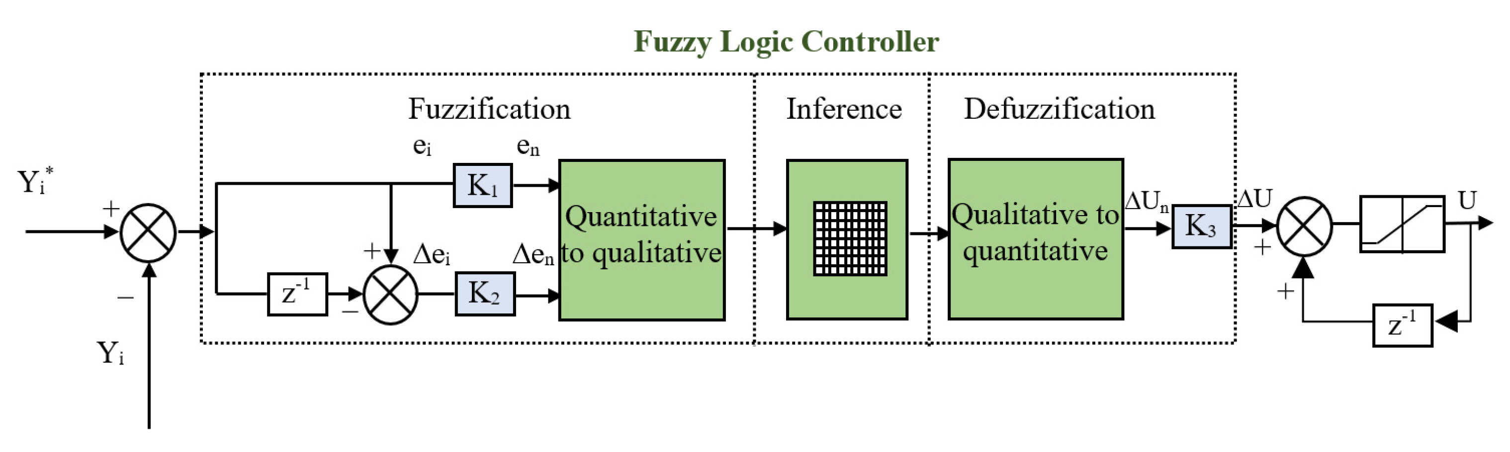
3. Fuzzy Logic Controller for AFPM Machine

In the 1960s, Zadeh [27] established the fuzzy logic theory to model complex systems that cannot be modeled with traditional theories using an extension of Boolean logic (0 or 1) to graded logic (0 to 1). Nowadays, the fuzzy logic theory is of current interest for various applications and especially for process control [28,29].
In a classical way, the internal structure of a fuzzy proportional intergral control system is based on three blocks (Fuzzification, Inference and Defuzzification) as we can see in Figure 2.

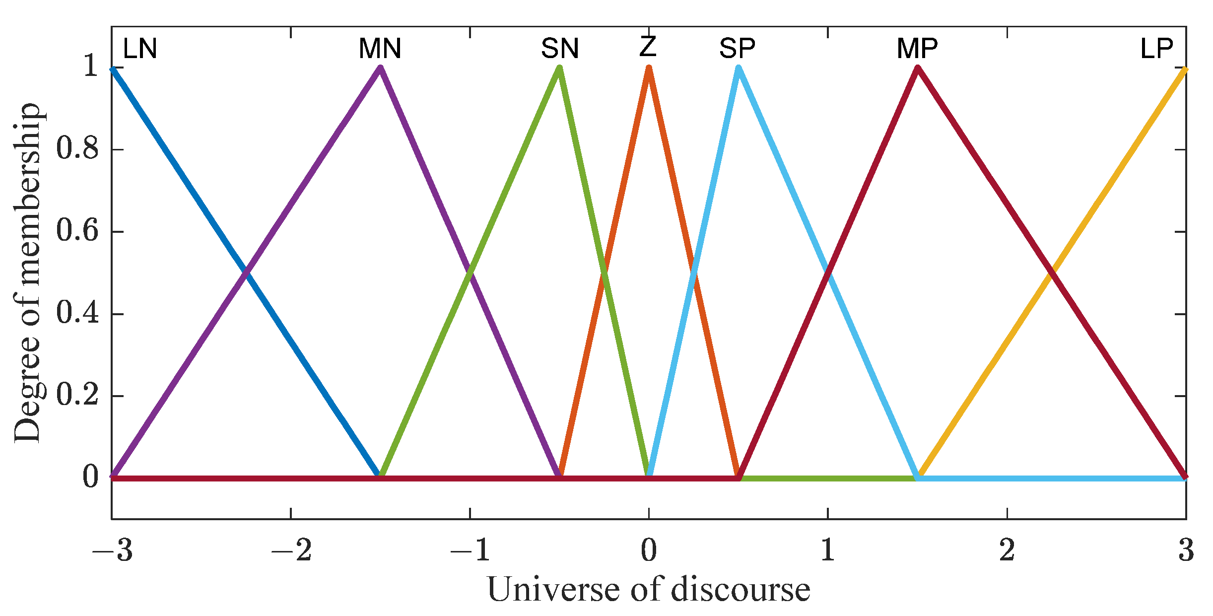
3.1. The Fuzzification of Input Variables

The fuzzification is the process consisting of defining the membership functions for the different input and output variables. For this, we define seven linguistic sets with 50% overlapping (Large Positive, Medium Positive, Small Positive, Zero, Small Negative, Medium Negative and Large Negative) as shown in Figure 3. In our case, the inputs are the dq current errors ( e d / e q ) and their derivatives   ( Δ e d / Δ e q ) ,   which are then reduced to normalized quantities on the universe of discourse [−3,3] using scaling factors K1, K2 and K3. Figure 4 represents the evolution of the FLC output as a function of the normalized inputs (e, ∆e):
where { e d ( i ) = i d s ( i ) * i d s ( i ) e q ( i ) = i q s ( i ) * i q s ( i ) and { Δ e d ( i ) = e d ( i ) e d ( i 1 ) Δ e q ( i ) = e q ( i ) e q ( i 1 )

3.2. Inference Engine from a Knowledge Base

The inference block is the core of the FLC controller. Indeed, it has the ability to simulate human decisions and infer fuzzy control actions using fuzzy implication and inference rules as defined in Table 1, which are very close to the Mac Vicar Whelan rules [30] that can be described as follows:
if e is LN and Δe is LP, then s is LP or;
if e is LP and Δe is MP, then s is MP or …
To make the control decision, we use the Max–Min inference method of Mamdani with the fuzzy implication of the (AND) operator realized by the minimum function and the (OR) operator by the maximum function.

3.3. Defuzzification

The defuzzification defines the control law of the FLC. It allows us to realize the inverse conversion of the fuzzification, which will generate a numerical value from the set obtained by the composition of the rules. To compute the output value of the FLC, we use the center of gravity method defined in (12), which consists of computing the abscissa of the center of gravity of the resulting membership function as:
Δ u = i = 1 i = n u i μ ( u i ) i = 1 i = n μ ( u i )
where n is the number of the membership function, ui is the center of the ith fuzzy set and μ(ui) is the membership degree of ui.

4. Experimental Results under Healthy and Faulty Conditions

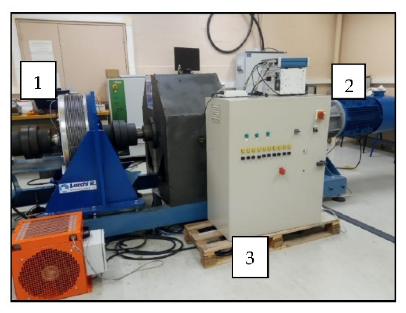
4.1. Test Bed Presentation

Figure 5a resumes the control scheme of the 6P-AFPMSM using the FLC technique while Figure 5b depicts the diagram of the experimental setup. As we can see in Figure 5b, the 6P-AFPMSG is driven by a geared motor, which is a classical three-phase machine (45 KW) considered as a wind emulator with an output ratio of 1:11. The latter is controlled via an industrial variable speed regulator in order to impose the desired output speed with a range of variation between 0 and 133 rpm. Therefore, the electromagnetic torque of the generator is imposed by choosing different values of the q-axis stator current reference. The power is extracted via two back-to-back converters with a rated power of 15 kVA. These converters are controlled by an industrial computer programmed in real time with MATLAB/Simulink® software version R2012b (by MathWorks based in Natick, MA, USA) and with a sampling frequency of 10 kHz. The loss of phase is achieved manually by opening the circuit with relay switches after the machine converters. The experimental test bench is presented in Figure 6. A flow chart for the overall process is given in the Appendix B.

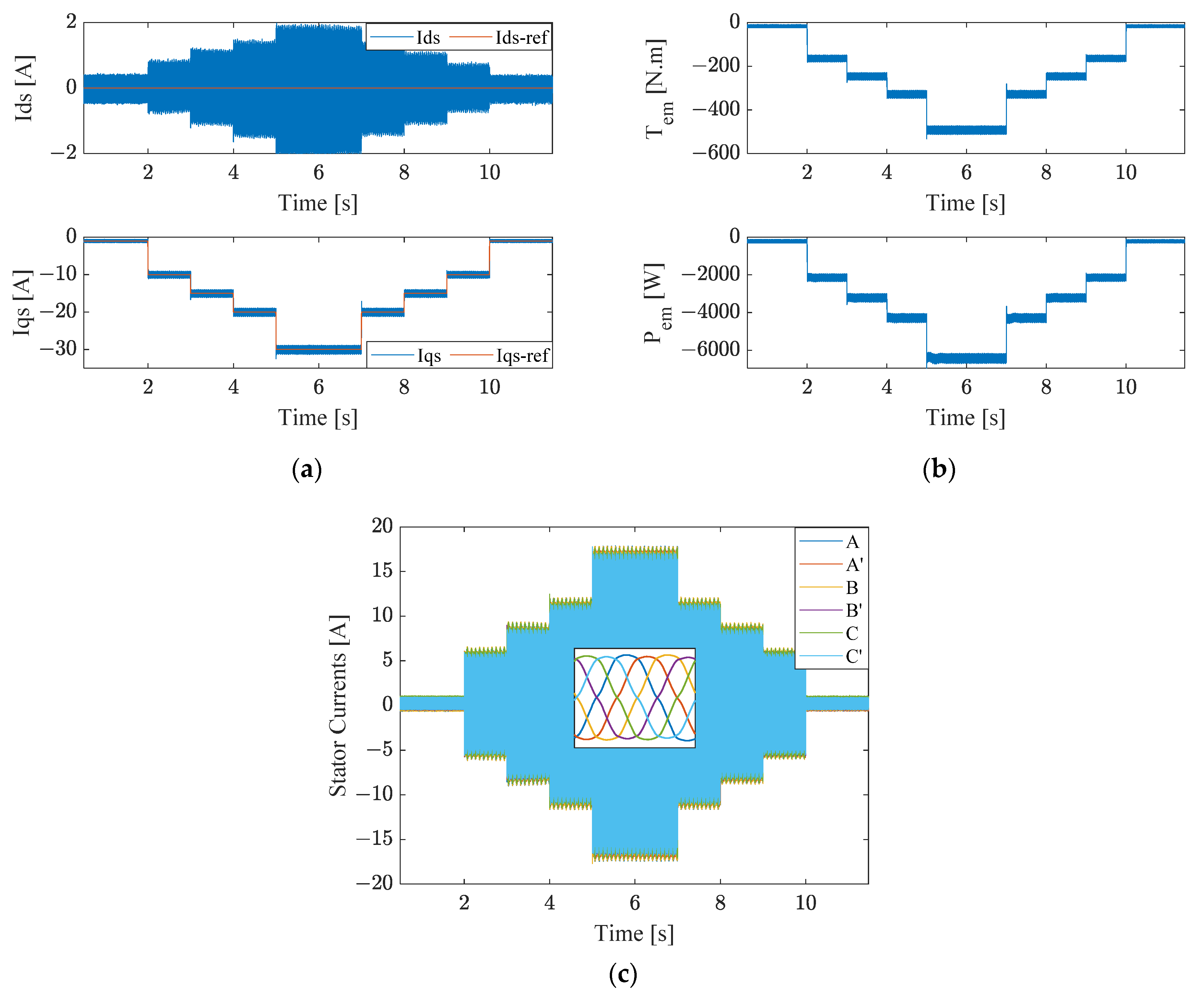
4.2. Healthy Mode Operation

The speed of the shaft is kept constant at 125 rpm via the industrial variable speed converter, and different reference values for the q axis current are imposed to test the tracking performance of the proposed controller.
Figure 7a and Figure 8a present the dq currents with the PI controller and the FLC, respectively. Figure 7b and Figure 8b represent the electromagnetic torque and the extracted power while Figure 7c and Figure 8c depict the stator currents with the both controllers.
With the two controllers, the reference values are reached, but we can see that the performance of the FLC is much better than the one with the PI controller, since the power ripples around the reference are smaller with the FLC (Figure 8b) than with the PI controller (Figure 7b). Furthermore, we can see in Figure 7a with the PI controller that variations of reference on the q-axis stator current induces ripples on the d-axis stator current. These ones are due to the fact that, with FOC, the d- and q-axis stator currents are not completely decoupled in the machine. This effect is minimized using the FLC, as can be seen in Figure 8a.

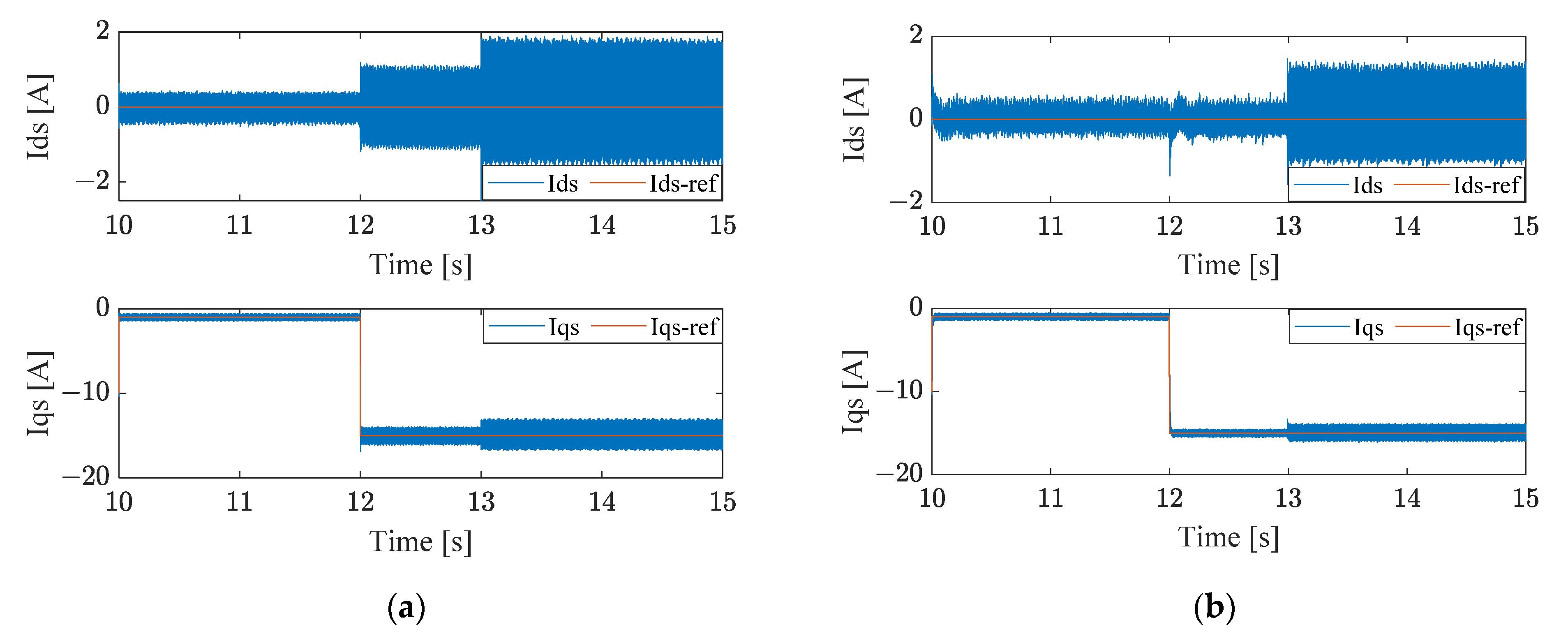
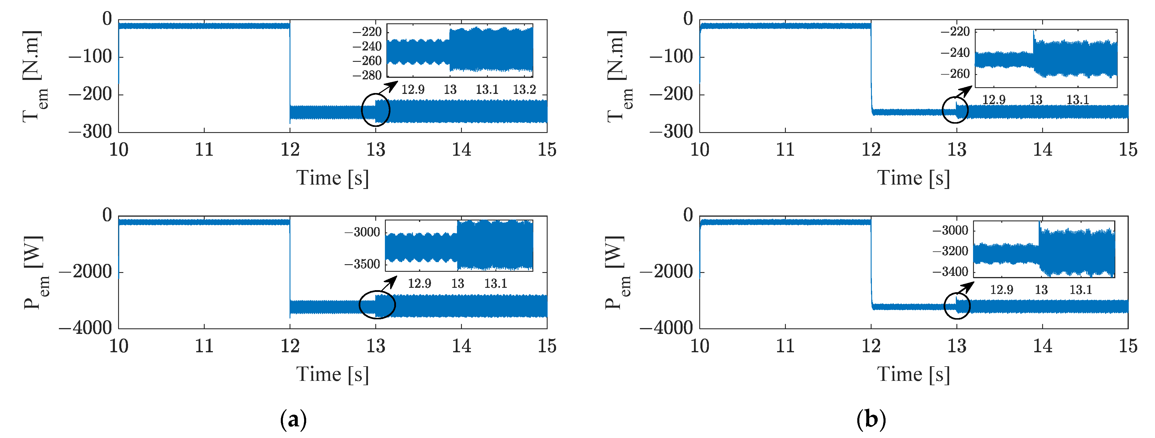
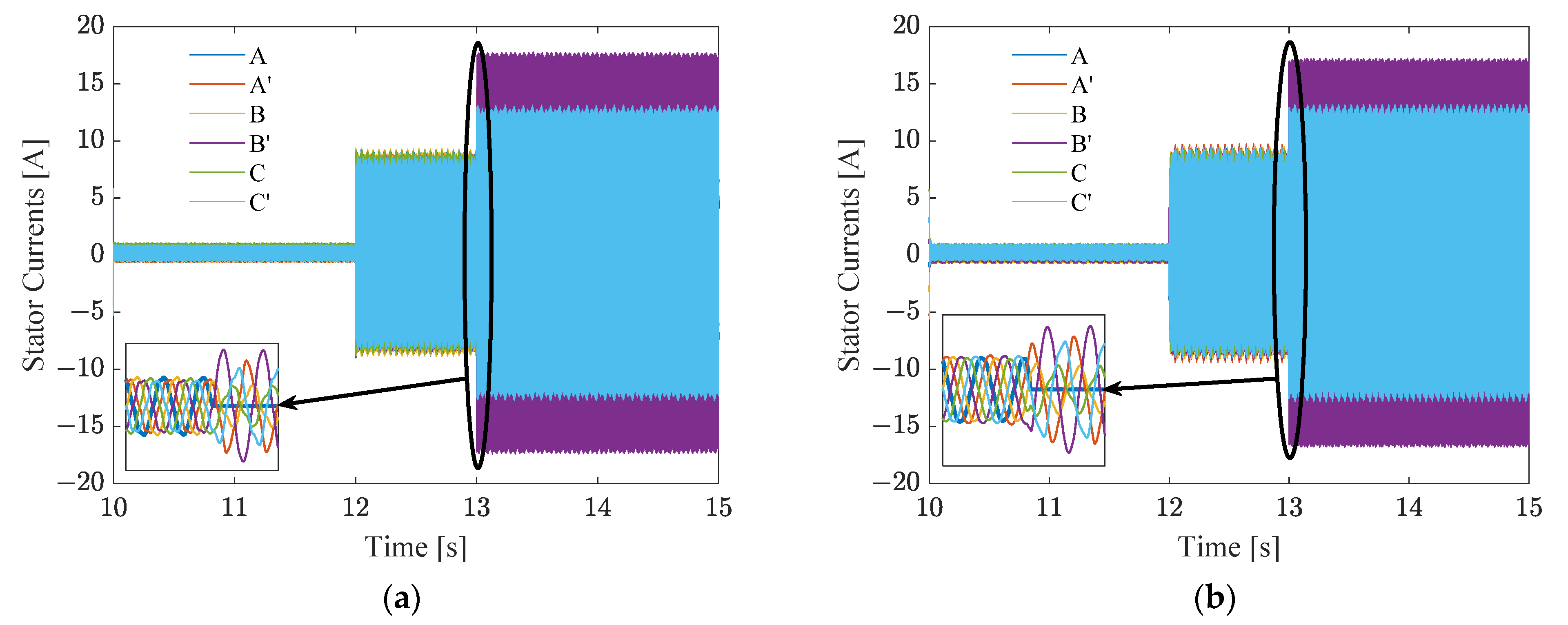
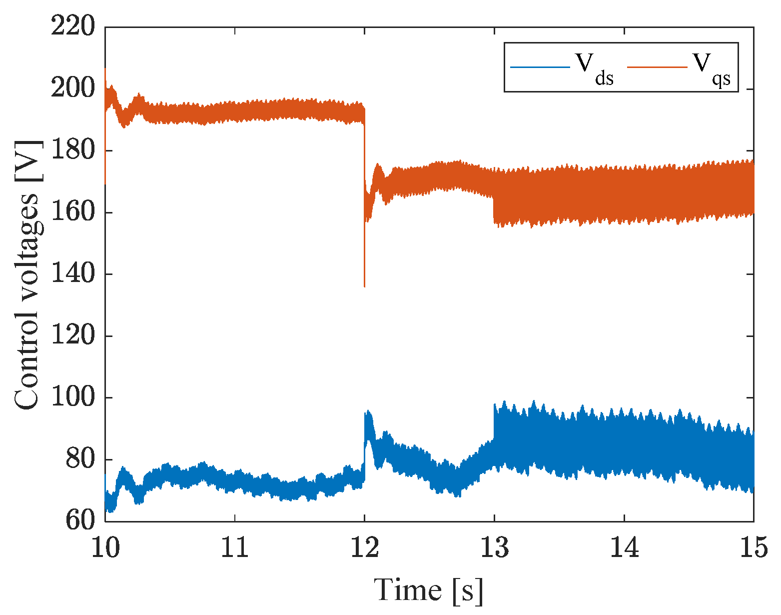
4.3. Faulty Mode Operation with One Open-Phase

The rotor speed is still set at 125 rpm, the reference for the quadrature current is fixed at −15 A at time t = 12 s and the open-phase fault is induced at time t = 13 s. As in healthy mode, Figure 9 represents the dq currents with the PI controller (a) and with FLC (b) while Figure 10 depicts the electromagnetic torque and power. Figure 11 describes the stator currents with the PI controller and the FLC, respectively.
One can see in Figure 9a (PI controller) that the transition between −1 A and −15 A induces ripples in the direct current, and these ripples become more significant after the phase loss. These ripples in the dq current components are reflected in the electromagnetic torque by increasing the ripples from 30 Nm in healthy mode to 40 Nm in faulty mode (Figure 10a) with the PI controller. Furthermore, the same conclusion can be made for the extracted power moving from 250 W to 500 W. With the FLC, the dq currents (Figure 9a) present a slight variation compared to the PI controller with lower ripples on electromagnetic torque from 10 Nm in healthy mode to 30 Nm in faulty mode and from 100 W to 350 W for the electromagnetic power as shown in Figure 10b. Figure 11a,b represent the stator currents that become naturally unbalanced after the loss of one phase with PI controller and FLC.

5. Discussion

Figure 12 and Figure 13 show Vds and Vqs voltages applied to the machine for both controller methods under healthy (12–13 s) and faulty (13–15 s) conditions, respectively. We can clearly notice that the FLC is very suitable with less ripples in healthy and faulty conditions, compared to the conventional PI controller, which presents higher ripple magnitudes and that can lead to stressing and damaging the machine.
The Table 2 and Table 3 show another comparison in terms of the mean square error (MSE) approach of the dq stator currents in healthy and faulty modes with a PI controller and an FLC. By comparing the MSE of both controllers, we can remark the better tracking performance of the proposed FLC with minimal error in both conditions compared to PI controller.

6. Conclusions

In this paper, the association of FLC with the FOC technique for an axial flux multiphase permanent magnet machine is experimentally tested and then compared with a classical PI controller in healthy and faulty conditions. A 6P-AFPMSM with a double-sided configuration is a complex nonlinear system with uncertainties of parameters, thus the need for a robust and powerful controller. The experimental results illustrate the advantage of using an FLC over the traditional PI controller. Indeed, the FLC guarantees the adaptation of the control voltage to the error and its variation which allows to have a good setpoint tracking with less ripples and also robustness to the disturbances caused by the phase loss without requiring a phase fault detection algorithm.
Nevertheless, the determination of the FLC scaling factors has been realized using the knowledge of the system dynamics, and it could be a challenge to define an intelligent algorithm able to compute the suitable values whatever the generation machines (synchronous or induction).
For the future works, we will focus on testing the FLC with two to three missing phases and comparing the FLC with another advanced controllers such as variable structure controllers.

Author Contributions

Conceptualization, O.B., F.B. and A.Y.; methodology, O.B., F.B. and A.Y.; software, O.B., F.B. and A.Y.; validation, O.B., F.B. and A.Y.; formal analysis, O.B., F.B. and A.Y.; investigation, O.B., F.B. and A.Y.; resources, O.B., F.B. and A.Y.; data curation, O.B., F.B. and A.Y.; writing—original draft preparation, O.B., F.B. and A.Y.; writing—review and editing, O.B., F.B. and A.Y.; visualization, O.B., F.B. and A.Y.; supervision, F.B. and A.Y.; project administration, F.B. and A.Y.; funding acquisition, F.B. and A.Y.. All authors have read and agreed to the published version of the manuscript.

Funding

This research was funded by the European Regional Development Fund and Grand-Soissons Agglomeration.

Institutional Review Board Statement

Not applicable.

Informed Consent Statement

Not applicable.

Data Availability Statement

Not applicable.

Acknowledgments

The authors gratefully acknowledge the «Hauts de France» Region Council, the European Regional Development Fund (ERDF) and Grand-Soissons Agglomeration for the financial support provided.

Conflicts of Interest

The authors declare no conflict of interest.

Appendix A

Table A1. Rated parameters of the 6P-AFPMSM.
ParameterValueUnits
Rated Power24kW
Rated Torque1800Nm
Rated Voltage160V
Rated Current 47A
Frequency33Hz
Number of pole pairs16-
Stator resistance Rs0.139
d-axis inductance Lds0.0026H
q-axis inductance Lqs0.0026H
Nominal speed125rpm
RMS Back EMF constant0.72V/rad/s

Appendix B

Figure A1. Flowchart of the overall process.
Energies 15 01301 g0a1

Appendix C

PI-Controller gains using pole placement approach.
k i = L d q ω n 2 ; k p = 2 ξ k i ω n R s
Table A2. PI-Controller Parameters of the 6P-AFPMSM.
ParameterValueUnits
Optimal   damped   coefficient   ζ 0.707-
Natural   frequency ω n 1000rad/s
Ki(dq)2600-
Kp(dq)3.54-

Appendix D

Figure A2. 6P-AFPMSM structure.
Energies 15 01301 g0a2

References

  1. Global Wind Report 2021. Available online: https://gwec.net/global-wind-report-2021/ (accessed on 9 September 2021).
  2. Pantea, A.; Yazidi, A.; Betin, F.; Capolino, G.A.; Lanfranchi, V. Six-phase Axial Flux Permanent Magnet generator model: Simulation and experimental validation. In Proceedings of the 2016 IEEE 25th International Symposium on Industrial Electronics (ISIE), Santa Clara, CA, USA, 8–10 June 2016; pp. 192–197. [Google Scholar] [CrossRef]
  3. Anvari, B.; Guedes-Pinto, P.; Lee, R. Dual Rotor Axial Flux Permanent Magnet Motor using PCB Stator. In Proceedings of the 2021 IEEE International Electric Machines & Drives Conference (IEMDC), Hartford, CT, USA, 17–20 May 2021; pp. 1–7. [Google Scholar]
  4. Radwan-Pragłowska, N.; Węgiel, T.; Borkowski, D. Modeling of Axial Flux Permanent Magnet Generators. Energies 2020, 13, 5741. [Google Scholar] [CrossRef]
  5. Flah, A.; Khan, I.A.; Agarwal, A.; Sbita, L.; Simoes, M.G. Field-oriented control strategy for double-stator single-rotor and double-rotor single-stator permanent magnet machine: Design and operation. Comput. Electr. Eng. 2021, 90, 106953. [Google Scholar] [CrossRef]
  6. Zhao, J.; Zheng, L.; Wang, S.; Hua, M. Research on Deadbeat Current Prediction Vector Control System of Axial Flux Permanent Magnet Synchronous Motor for Electric Bus Based on Efficiency Optimal Torque Distribution Method. IEEE Access 2019, 7, 128384–128393. [Google Scholar] [CrossRef]
  7. Pirzad, S.; Ghadimi, A.A.; Abolmasoumi, A.H.; Jabbari, A.; Bagheri, S. Optimal mixed control of Axial Flux Permanent Magnet Synchronous generator wind turbines with modular stator structure. ISA Trans. 2021, 115, 153–162. [Google Scholar] [CrossRef] [PubMed]
  8. Bouyahia, O.; Betin, F.; Yazidi, A. Fault-tolerant Variable Structure Control Of a Low Speed 6-Phase Induction Generator. In Proceedings of the 2021 IEEE 13th International Symposium on Diagnostics for Electrical Machines, Power Electronics and Drives (SDEMPED), Dallas, TX, USA, 22–25 August 2021; Volume 1, pp. 92–98. [Google Scholar] [CrossRef]
  9. Che, H.S.; Hew, W.P. Dual three-phase operation of single neutral symmetrical six-phase machine for improved performance. In Proceedings of the IECON 2015—41st Annual Conference of the IEEE Industrial Electronics Society, Yokohama, Japan, 9–12 November 2015; pp. 001176–001181. [Google Scholar] [CrossRef]
  10. Liu, Z.; Zheng, Z.; Xu, L.; Wang, K.; Li, Y. Current Balance Control for Symmetrical Multiphase Inverters. IEEE Trans. Power Electron. 2016, 31, 4005–4012. [Google Scholar] [CrossRef]
  11. Mule, G.J.A.; Munim, W.N.W.A.; Tousizadeh, M.; Abidin, A.F. Post-fault tolerant of symmetrical six-phase induction machine under open circuit fault with single and two isolated neutral points using graphical user interface. AIP Conf. Proc. 2019, 2173, 020016. [Google Scholar] [CrossRef]
  12. Gonzalez-Prieto, A.; Gonzalez-Prieto, I.; Yepes, A.G.; Duran, M.J. Symmetrical Six-Phase Induction Machines: A Solution for Multiphase Direct Control Strategies. In Proceedings of the 2021 22nd IEEE International Conference on Industrial Technology (ICIT), Valencia, Spain, 10–12 March 2021; p. 6. [Google Scholar]
  13. Liang, Z.; Liang, D.; Kou, P.; Jia, S. Postfault control and harmonic current suppression for a symmetrical dual three-phase SPMSM drive under single-phase open-circuit fault. IEEE Access 2020, 8, 67674–67686. [Google Scholar] [CrossRef]
  14. Cervone, A.; Slunjski, M.; Levi, E.; Brando, G. Optimal Third-Harmonic Current Injection for Asymmetrical Multiphase Permanent Magnet Synchronous Machines. IEEE Trans. Ind. Electron. 2021, 68, 2772–2783. [Google Scholar] [CrossRef] [Green Version]
  15. Slunjski, M.; Dordevic, O.; Jones, M.; Levi, E. Symmetrical/asymmetrical winding reconfiguration in multiphase machines. IEEE Access 2020, 8, 12835–12844. [Google Scholar] [CrossRef]
  16. Xu, J.; Odavic, M.; Zhu, Z.Q.; Wu, Z.; Freire, N.M.A. A Generalized Decomposition Model of Dual Three-Phase Permanent Magnet Synchronous Machines Considering Asymmetric Impedances and Compensation Capability. IEEE Trans. Ind. Appl. 2021, 57, 3763–3775. [Google Scholar] [CrossRef]
  17. Li, W.; Feng, G.; Li, Z.; Tjong, J.; Kar, N. MultiReference Frame Based OpenPhase Fault Modeling and Control for Asymmetrical SixPhase Interior Permanent Magnet Motors. IEEE Trans. Power Electron. 2021, 36, 11712–11725. [Google Scholar] [CrossRef]
  18. Kali, Y.; Saad, M.; Rodas, J.; Mougharbel, I.; Benjelloun, K. Robust control of a 6-phase induction generator for variable speed wind energy conversion system. In Proceedings of the 2020 5th International Conference on Renewable Energies for Developing Countries (REDEC), Marrakech, Morocco, 29–30 June 2020; pp. 1–6. [Google Scholar]
  19. Pantea, A.; Bouyahia, O.; Abdallah, A.; Yazidi, A.; Betin, F. Fault Tolerant Fuzzy Logic Control of a 6-Phase Induction Generator for Wind Turbine Energy Production. Electr. Power Compon. Syst. 2021, 1–11. [Google Scholar] [CrossRef]
  20. Pantea, A.; Nurwati, T.; Yazidi, A.; Betin, F.; Carriere, S.; Capolino, G. Fuzzy Logic Control of a Low Speed Six-Phase Induction Generator for Wind Turbines. In Proceedings of the IECON 2018—44th Annual Conference of the IEEE Industrial Electronics Society, Washington, DC, USA, 21–23 October 2018; pp. 5813–5818. [Google Scholar] [CrossRef]
  21. Corinthios, M. Signals, Systems, Transforms, and Digital Signal Processing with MATLAB (Chapter 5: System Modeling, Time and Frequency Response); CRC Press: Boca Raton, FL, USA, 2018; ISBN 1-4200-9049-6. [Google Scholar]
  22. Huang, S.; Aydin, M.; Lipo, T.A. TORUS concept machines: Pre-prototyping design assessment for two major topologies. In Proceedings of the Conference Record of the 2001 IEEE Industry Applications Conference. 36th IAS Annual Meeting (Cat. No.01CH37248), Chicago, IL, USA, 30 September–4 October 2001; Volume 3, pp. 1619–1625. [Google Scholar] [CrossRef]
  23. Kahourzade, S.; Mahmoudi, A.; Ping, H.W.; Uddin, M.N. A comprehensive review of axial-flux permanent-magnet machines. Can. J. Electr. Comput. Eng. 2014, 37, 19–33. [Google Scholar] [CrossRef]
  24. Capponi, F.G.; De Donato, G.; Caricchi, F. Recent advances in axial-flux permanent-magnet machine technology. IEEE Trans. Ind. Appl. 2012, 48, 2190–2205. [Google Scholar] [CrossRef]
  25. Chinchilla, M.; Arnaltes, S.; Burgos, J.C. Control of permanent-magnet generators applied to variable-speed wind-energy systems connected to the grid. IEEE Trans. Energy Convers. 2006, 21, 130–135. [Google Scholar] [CrossRef] [Green Version]
  26. Levi, E. Multiphase AC Machines. In The Industrial Electronics Handbook; CRC Press: Boca Raton, FL, USA, 2011. [Google Scholar] [CrossRef]
  27. Klir, G.J.; Yuan, B. Fuzzy Sets, Fuzzy Logic, and Fuzzy Systems: Selected Papers by Lotfi A Zadeh; World Scientific: Singapore, 1996; Volume 6, ISBN 981-4499-81-1. [Google Scholar]
  28. Betin, F.; Pinchon, D.; Capolino, G.-A. Fuzzy logic applied to speed control of a stepping motor drive. IEEE Trans. Ind. Electron. 2000, 47, 610–622. [Google Scholar] [CrossRef]
  29. Fnaiech, M.A.; Betin, F.; Capolino, G.-A.; Fnaiech, F. Fuzzy logic and sliding-mode controls applied to six-phase induction machine with open phases. IEEE Trans. Ind. Electron. 2009, 57, 354–364. [Google Scholar] [CrossRef]
  30. Goguen, J.A.; Zadeh, L.A. Fuzzy sets. Information and control. J. Symb. Log. 1973, 38, 656–657. [Google Scholar] [CrossRef]
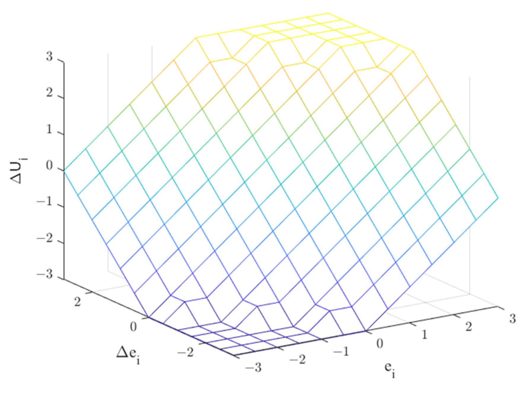
Figure 1. (a) Stator Winding configurations; (b) 6P-AFPMSM.
Energies 15 01301 g001
Figure 2. Fuzzy Proportional Integral control system.
Energies 15 01301 g002
Figure 3. Fuzzy sets membership for inputs (e, ∆e) and output ∆U.
Energies 15 01301 g003
Figure 4. Real output surface ∆U of the fuzzy PI controller as a function of the real inputs (e, ∆e).
Energies 15 01301 g004
Figure 5. (a) Control scheme of 6P-AFPMSM; (b) Diagram of the experimental setup.
Energies 15 01301 g005
Figure 6. Experimental test bench.
Energies 15 01301 g006
Figure 7. Healthy mode results with PI controller: (a) dq currents; (b) electromagnetic torque and electromagnetic power; (c) stator currents.
Energies 15 01301 g007
Figure 8. Healthy mode results with FLC controller: (a) dq currents; (b) electromagnetic torque and electromagnetic power; (c) stator currents.
Energies 15 01301 g008
Figure 9. Faulty mode results: (a) dq currents with PI controller; (b) dq currents with FLC.
Energies 15 01301 g009
Figure 10. Faulty mode results of electromagnetic torque and power: (a) with PI controller; (b) with FLC.
Energies 15 01301 g010
Figure 11. Faulty mode results: (a) stator currents with PI controller; (b) stator currents with FLC.
Energies 15 01301 g011
Figure 12. dq control voltages with PI controller in healthy and faulty modes.
Energies 15 01301 g012
Figure 13. dq control voltages with FLC in healthy and faulty modes.
Energies 15 01301 g013
Table 1. Base of rules for FLC.
eeLNMNSNZESPMPLP
LPZESPMPLPLPLPLP
MPSNZESPMPLPLPLP
SPMNSNZESPMPLPLP
ZELNMNSNZESPMPLP
SNLNLNMNSNZESPMP
MNLNLNLNMNSNZESP
LNLNLNLNLNMNSNZE
Table 2. Numerical comparison of PI controller and FLC under d-axis current.
ApproachMSE(ids)MSE(ids)
Times (s) 12–1313–15
PI Controller0.44250.8023
Fuzzy Logic Controller0.05700.3194
Table 3. Numerical comparison of PI controller and FLC under q-axis current.
ApproachMSE(iqs)MSE(iqs)
Times (s) 12–1313–15
PI Controller0.39910.7938
Fuzzy Logic Controller0.19960.4296
Publisher’s Note: MDPI stays neutral with regard to jurisdictional claims in published maps and institutional affiliations.

