
Robust Errorless-Control-Targeted Technique Based on MPC for Microgrid with Uncertain Electric Vehicle Energy Storage Systems

School of Marine Science and Technology, Northwestern Polytechnical University, Xi’an 710072, China
*
Authors to whom correspondence should be addressed.
Energies 2022, 15(4), 1398; https://doi.org/10.3390/en15041398
Submission received: 13 December 2021
/
Revised: 26 January 2022
/
Accepted: 8 February 2022
/
Published: 15 February 2022
(This article belongs to the Special Issue Next Generation Energy and Propulsion Systems for Transportation Electrification)
Abstract
:Regarding the microgrid with large-scale electric vehicle (EV) energy storage systems working at the vehicle-to-grid (V2G) mode, uncertain factors (e.g., the number of EVs feeding the microgrid shifts frequently) make the system unfixed, leading to the fact that it is difficult to precisely determine the real-time droop coefficients of the system, thereby degrading the performance of the traditional inverter control strategies that rely on the droop coefficients. To solve the problem, this paper proposes an errorless-control-targeted double control loop (DCL) technique based on robust MPC to control the microgrid with EV energy storage systems without using droop coefficients. Firstly, the structure of the DCL method is developed, with each component in the structure detailed. Compared to the traditional control strategies, the novel one regards the frequency, voltage, and currents as the control objectives instead of active/inactive power. It deserves to be mentioned that the frequency and voltage are regulated by proportional-integral controllers, while the currents are regulated by the finite control set model predictive control (FCS-MPC) method. Secondly, the impacts of system parameter uncertainties on the prediction accuracy of the FCS-MPC controller are analyzed clearly, illustrating that it is necessary to develop effective techniques to enhance the robustness of the controller. Thirdly, sliding mode observers (SMO) based on a novel hyperbolic function are constructed to detect the real-time disturbances, which can be used to generate voltage compensations by using automatic disturbance regulators. Then, the voltage compensations are adopted to establish a modified predicting plant model (PPM) used for the FCS-MPC controller. By using the proposed SMO-based disturbance detection and compensation techniques, the MPC controller gains a strong robustness against parameter uncertainties. Finally, a simulation is conducted on a microgrid system to verify the effectiveness of the proposed techniques, and the obtained results are compared with the traditional virtual synchronous machine (VSG) strategy relying on droop coefficients.
1. Introduction
Nowadays, the microgrid which contains distributed generation (e.g., photovoltaic, wind, and tidal generation, etc.) and energy storage (e.g., batteries and super-capacitors, etc.) is one of the most promising power generation and supply systems because it has the advantages of high flexibility, eco-friendliness and sustainability [1,2]. Apart from feeding and supporting the conventional grid (grid-connected mode), microgrids play an important role in forming the grid (island mode) [3]. When the microgrid operates at the island mode (see Figure 1), it needs to independently supply power for the local DC/AC loads, such as electric vehicles (EVs), household and industrial electric apparatuses, etc. [4]. Among those loads, EVs are special because they have rechargeable energy storage systems (RESS), and as a result, they can feed the DC-bus of the microgrid when the other types of loads are heavy. The technology is known as vehicle-to-grid (V2G) [5].
However, as for the EVs used in the applications of V2G, they are uncertain factors for the microgrid. The dynamic model of the EV energy storage system can be qualitatively represented as (1). It can be seen that the supporting power from the EVs is related to the number of charging piles n, the number of vehicles working at the V2G mode (n·c), and the supporting period of the EVs (tsu). In detail, the uncertainties are reflected in the following four aspects. (1) More charging piles might be installed in one microgrid system. (2) The number of EVs connected with the microgrid varies in different periods. (3) Even though the charging piles installed within the microgrid are fully occupied, it does not mean that all of them are available for supporting the microgrid. Usually, whether a vehicle can provide energy to the grid will depend on the EV owners. (4) EVs that are supplying power to the grid may end at any time. These uncertainties lead to the fact that the power level (rated power) of the microgrid is not fixed, bringing about challenges for the DC/AC inverter control strategies [6]. Specifically, the commonly used inverter control techniques for the microgrid include droop control and virtual synchronous generator (VSG) control [7,8]. Droop control used for the microgrid originates from the conventional grid. It can be categorized into P-f/Q-V control and f-P/V-Q control, and the differences between them can be reflected by their control topology [9,10,11]. Considering that the droop control has the disadvantages of small inertia and insufficient damping, it will generate remarkable voltage and frequency fluctuations or deviations when the loads change [12]. To improve the inertia and damping of the system, VSG control technology that simulates the behaviors of the real synchronous generators has been studied since 2007 [13,14,15,16,17,18,19]. It deserves to be mentioned that as for the VSG control method (see Figure 1), f-P/Q-V droop control still needs to be incorporated. Overall, droop controllers cannot be eliminated for the above two traditional control methods, thereby requiring droop coefficients. However, when the uncertainties of the EVs are taken into account, the droop coefficients cannot maintain at a certain level because the power supply system (hardware and power level) is inclined to change [20]. In this case, the performance of the traditional control strategies based on droop control will decline unless the real-time droop coefficients cannot be provided.
With reference to [21,22,23,24,25], to solve the uncertainty problem arising from the droop coefficients, two methods can be potentially adopted, that is, adaptive droop coefficients and coefficient elimination. In [21], the fuzzy logic-based and model reference-based adaptive droop coefficient design methods are presented to adjust the adaptability of the droop controllers, improving the transient response of the system. Reference [22] introduces a method that upgrades the droop coefficients based on a sliding mode strategy to optimize the power-sharing operations. In [23], for the sake of high performance, a stability-constrained adaptive droop approach is proposed for autonomous power-sharing of the grid. In [24], a VSG-based method with adaptive active power and DC voltage droop control is proposed to regulate the voltage and frequency of the grid. In this study, the droop coefficients are adaptively adjusted depending on the frequency margin of the system. Literature [25] illustrates that without adding a droop controlling unit, the power, frequency, and voltage can also be controlled by using the closed-loop feedback control technique, but no new control schemes are developed in this research. It deserves to be mentioned that compared to the research concerning adaptive droop coefficients, there are much fewer studies concerning the droop coefficient elimination strategies today. Hence, it is a valuable and timely measure to further investigate the control theories without using droop controllers and droop coefficients.
One main purpose of this paper is to develop a double-closed-loop (DCL) control strategy to directly regulate the voltage and frequency (the ultimate control objectives) of the microgrid with large-scale EVs connected. The outer loop will be the voltage and frequency control, while the inner loop will be the current control one. The goal of the proposed DCL control strategy is to ensure voltage and frequency are maintained at the desired level constantly without errors, regardless of the changes of load and EVs. Because the voltage, frequency, and currents are direct control targets, it is not necessary to employ droop controllers to generate voltage and frequency references. Therefore, the droop coefficients can be avoided. When achieving the errorless DCL control scheme, the most direct way is to adopt several (at least four) proportional-integral (PI) controllers to regulate the voltage, frequency, and currents. However, [26] and [27] clarify that the PI controllers have the disadvantages of complicated parameter tuning and low dynamics, leading to the fact that it is better to adopt the alternative controllers in the main structure.
Many optimization algorithms can be used to overcome the shortcomings of PI controllers. For example, [28] uses the model predictive control (MPC) method to manage energy resources efficiently. The author of [29] designs an optimal model predictive controller for the nonlinear multi-area power system, while [30] uses MPC to manage the power in a hydrogen-based microgrid. In [31], a new variable structure control method is proposed to regulate the frequency of the grid, while [32] proposes a gravitational search algorithm-based dual proportional-integral method to control the load frequency, which can be regarded as a typical application of the future search algorithms for optimization [33]. Among those strategies, MPC is characterized by online optimization and quick response, thereby being a promising alternative [34]. However, because MPC is a model-based control strategy, its performance highly relies on the accuracy of the system parameters, including line resistance and inductance of the microgrids. Unfortunately, considering the complexity of the wiring, connections and working environment of the microgrids, the system parameters might change continuously [35,36]. As for the traditional fixed-parameter-based MPC methods, once the parameter mismatch phenomenon occurs, the prediction accuracy of the MPC controllers will degrade significantly. On this premise, if MPC is used to achieve the DCL control scheme, it is vital to develop effective strategies to enhance the robustness of MPC controllers against parameter uncertainties.
In this paper, we propose a novel DCL strategy based on robust MPC theory to achieve errorless frequency and voltage regulation for the microgrids with uncertain EV energy storage systems. The novelties and contributions can be summarized as follows:
- (1)
- The structure of the novel DCL control method is developed, with the details of each internal component presented. In comparison with the traditional droop control and VSG control strategies, droop controllers are not needed any longer, thereby avoiding the droop coefficients. As for the microgrids with uncertain EV energy storage systems, when the AC loads are heavy, the overall power provided by the EVs can be automatically determined by using the errorless-control-targeted scheme, and the maximum power that can be provided by each EV can be restrained by setting the maximum allowable discharge current.
- (2)
- After establishing a disturbance-based predicting plant model (PPM), the impacts of line resistance and inductance on the prediction accuracy of the FCS-MPC method are studied in the area of microgrid control, addressing the necessity of developing the robust MPC technique.
- (3)
- Sliding mode observers (SMO) based on the novel hyperbolic function are developed to detect the real-time disturbances which can be further used to generate voltage compensations by controlling them to maintain at zero. This is new in the area of microgrid control. In order to make the SMOs stable, Lyapunov functions are constructed to design the parameters of the observers. It deserves to be mentioned that the voltage compensations need to be substituted into the PPM to select the optimal voltage vector applied to the inverter, improving the prediction accuracy. By using the proposed SMO-based disturbance detection and compensation techniques, the MPC controller is endowed with strong robustness against parameter uncertainties.
The structure of the rest of the paper is as follows: Section 2 introduces the structure of the proposed DCL control strategy with a traditional MPC controller in comparison to the VSG method. The mechanisms and implementations of each part in the structure are discussed. In Section 3, the impacts of the parameter mismatch on the prediction accuracy of the traditional MPC method are analyzed firstly. Then, the sliding mode disturbance observers (SMDO) are constructed with their stability analyzed. Additionally, the implementation procedures of the proposed DCL technique based on the robust MPC controller are presented in this part. Section 4 discusses the simulation results of the proposed algorithms, and Section 5 is the conclusion.
2. Proposed Errorless-Control-Targeted DCL Strategy with Traditional MPC Controller
This section introduces the structure of the proposed errorless-control-targeted DCL strategy in comparison with the traditional VSG method. by firstly revealing the novelty of the new strategy. Secondly, each part of the DCL structure is illustrated in detail. Lastly, the working mechanism of the hardware system is explained.
2.1. Structure of Proposed DCL Control Strategy
Figure 2 depicts the structure of the proposed DCL control strategy for the microgrid working in the island mode. Being similar to the distributed generation and energy storage systems, the EV energy storage systems are regarded as the power source of the microgrid in Figure 2. Based on the aforementioned analysis, the EVs are uncertain sources. The new control strategy comprises a phase-locked loop (PLL) used to detect the real-time frequency; phase angle and magnitude of the voltage; d, q-axis current calculation part; automatic voltage regulator (AVR); and an automatic frequency regulator (AFR), which is used to achieve errorless voltage and frequency control, respectively; an MPC controller used for current regulation and pulse width modulation (PWM) signal selection; and the hardware system, which is the controlled object. Their details will be presented in the latter parts of this section. The main rationale behind the control technique can be described as follows: The detected frequency and voltage are regulated by PI controllers to maintain at the desired level, generating d, q-axis current references. Then, the feedback control theory is adopted for current regulation by using the MPC controller. The advantage of this method is that no droop controllers are adopted, avoiding the influence of the power uncertainties caused by the EVs.
By comparing the proposed method with the traditional VSG control strategy shown in Figure 1, five important differences reflecting the novelties of the proposed method can be summarized as follows (see Table 1). Firstly, as the active power and inactive power are not calculated and regulated, so the f-P and Q-V droop controllers are not needed to calculate the power and voltage references. Considering that voltage and frequency are the ultimate control objectives, they are directly regulated by the PI controllers without considering the intermediate variables (power). Without using droop coefficients, the EV energy storage system uncertainties will have few impacts on the control strategy. Secondly, in Figure 1, the voltage control process is an open-loop regulation, while, as for the proposed method, voltage feedback regulation is adopted, thus contributing to the voltage-errorless control. Thirdly, in terms of the VSG strategy, the feedback frequency is used to generate the active power reference, and further, the power is regulated by using the rotating function of the VSG. Essentially, this is a power-targeted control strategy; however, the method in Figure 2 is a frequency-errorless control strategy. Fourthly, the inactive current and active current are regulated by an MPC controller (inner loop), which is not focused on in the traditional VSG strategy. Finally, the PWM signal generation procedures are different. As for the VSG method, after the magnitude and phase angle of the desired voltage are calculated, the control signals are generated relying on the sine PWM (SPWM) theories. However, in Figure 2, the cost function of the MPC controller can select the optimal control signal after substituting the candidate voltage vectors into the PPM. It deserves to be mentioned that the latter one is easier to implement because it is based on the intuitive optimal control theory.
2.2. Details of Each Part of Proposed DCL Control Strategy
2.2.1. Real-Time Frequency, Phase Angle, and d, q-axis Voltage Detection
To obtain the real-time frequency, phase angle, and voltage magnitude of the microgrid, a three-phase PLL, of which the structure is depicted in Figure 3, is adopted. It deserves to be mentioned that the coordinate transformation part (abc/dq) satisfies the following condition [37]:
where T is the transformation matrix, and it is
Moreover, in Figure 3, the PI controller is used to regulate the errors between the d-axis voltage and the reference (zero), and its output is the angular frequency (ω) of the microgrid. After imposing integral operation and proportional operation on the angular speed, the phase angle, and frequency (in Hz) of the microgrid can be obtained as:
2.2.2. d, q-axis Current Calculation
After detecting the phase angle of the microgrid, the d, q-axis currents that are used for current regulation can be obtained by using the following equation:
2.2.3. Errorless Voltage and Frequency Control
In order to achieve errorless control, PI controllers are employed to regulate the voltage and frequency. For the AFR, input is the error between the frequency reference (rated frequency, e.g., 50 Hz) and the feedback frequency, while the output is set as the q-axis current reference iq* (related to the active power). In terms of the AVR, its input is the error between the magnitude of the rated voltage and the magnitude of the feedback voltage that can be calculated by (6). As for the output of the AVR, it is the d-axis current reference id* which is related to the inactive power of the microgrid.
The transfer functions of the AFR and AVR in the z-domain can be written as:
In practice, the proportional and integral factors in (7) need to be tuned. However, as for the proposed DCL control strategy that contains both PI controllers and MPC controllers, there exist no mature theories for analysis and parameter tuning. Hence, the trial-and-error strategy is more suitable to design the parameters of the AFR and AVR [38].
2.2.4. Traditional MPC Control
In terms of the two kinds of commonly used MPC controllers in the field of power electronic systems, namely, the continuous control set model predictive control (CCS-MPC) controller and FCS-MPC controller [39], the latter one is simpler to implement, bringing about a remarkable computational complexity reduction. This benefits from the look-up table of the candidate voltages, which can be obtained offline. Comparatively speaking, the computations of the CCS-MPC methods are much more complicated when executing the modulation algorithms. Hence, the FCS-MPC controller is adopted in this research. A discrete PPM is the prerequisite for achieving an FCS-MPC algorithm. Based on Figure 2, the state-space model of the microgrid in the d, q-axis frame can be established as follows:
Further, apply the Euler forward discretization algorithm to (8) in a time step of Ts (control period), and the future current states at tk+1 can be obtained as follows:
In (9), id,q(k) and ud,q(k) can be directly measured by using current and voltage sensors, while ed,q(k) should be calculated based on the candidate control voltages for an FCS-MPC controller. For instance, as far as a two-level inverter is concerned, when the FCS-MPC algorithm is implemented, seven candidate control voltages can be directly substituted into the model for prediction, which is denoted as u000, u100, u110, u010, u011, u001, and u101:
where [sa, sb, sc]T includes [0, 0, 0]T, [1, 0, 0]T, [1, 1, 0]T, [0, 1, 0]T, [0, 1, 1]T, [0, 0, 1]T, and [1, 0, 1]T, and they are the switching states. With reference to (2), the control voltage sets used for prediction in the d, q-axis frame can be expressed as:
After substituting the candidate voltages into (9) to calculate the predicted current values, a cost function should be used to select the optimal control voltage and the corresponding switching state to be applied to the inverter:
In terms of the FCS model predictive current control method, the following constraint needs to be incorporated:
As for the traditional FCS-MPC strategy, the resistances and inductances in (9) are fixed, which are usually measured (denoted as Rf_mea, Lf_mea, Rl_mea, and Ll_mea) by using the offline methods [40]. However, their real values are inclined to change as the working environment changes, degrading the prediction accuracy of the MPC controller. This can further bring about static voltage and frequency errors, failing the goal of errorless control. To solve the problem, a robust FCS-MPC control method against parameter uncertainties will be developed in Section 3.
2.2.5. Hardware System
As shown in Figure 2, the hardware directly controlled by the proposed DCL strategy is the DC/AC inverter, which will transmit the energy from the distributed generation system (DGS), inherent energy storage system, and EV storage system to the energy-consumption side. In the process of energy transmission, the goal is to automatically maintain the magnitude and frequency of the AC voltage at the rated levels through the proposed errorless control method. However, as for this system, there exist two crucial issues, (1) when the EV storage system feeds the microgrid, and (2) how to determine the maximum output power of one EV. In this paper, the working mechanisms of the EV storage system can be summarized as follows:
- Firstly, being similar to the traditional V2G technology, whether an EV begins to feed or stops feeding the microgrid, is determined by the vehicle owners. This can be achieved by using an app installed on their phones [41]. Secondly, the EV energy storage system works when it is needed. In detail, if the energy provided by the distributed generation and inherent storage systems is not enough to maintain the frequency and magnitude of the AC voltage at the rated level, the EV storage system will start to feed the grid. This phenomenon usually occurs when the AC loads are heavy, which reflect in the real-time voltage frequency and magnitude. Otherwise, the EV energy storage system is inactive.
- When the EVs provide energy to the microgrid, it is impossible to expect each vehicle to deliver unlimited power for the sake of safety. However, if no effective strategies are given to limit the output power of each vehicle, the horrible phenomenon might occur due to the proposed automatic control scheme when the microgrid voltage and frequency variations are extremely large. To solve the problem, considering that the output voltage of an EV energy storage system equals the DC-bus voltage Udc, as long as the output current of each system can be confined within their safe limits (determined by each vehicle) the EVs can work safely in the V2G process. It deserves to be mentioned that the maximum allowable output current of each EV system needs to be provided by the vehicle designers or manufacturers.
3. Robust SMDO-Based MPC Method
This section introduces the impacts of the system parameter uncertainties on the MPC control firstly. Secondly, the SMDOs are constructed, with their stability discussed in an innovative way. Then, the proposed disturbance impact elimination method based on voltage compensation is presented. Finally, the implementation procedures of the DCL strategy with a modified MPC controller are detailed.
3.1. Impacts of Parameter Uncertainties on MPC Controller
Assume that the deviations of the filter resistance, filter inductance, line resistance, and line inductance are ∆Rf, ∆Lf, ∆Rl, and ∆Ll, respectively, and then, the real parameters of the microgrid can be described as:
Substitute (14) into (8), the accurate system model can be rewritten as:
Further, by the use of the discretization algorithm, the discrete model can be obtained as:
It should be noted that fd(k) and fq(k) represent the d, q-axis current estimation errors when subtracting the PPM (9) with the measured parameters Rf_mea, Lf_mea, Rl_mea, and Ll_mea incorporated from (16). Obviously, when the parameter mismatch issue arises, the prediction accuracy of the traditional FCS-MPC method will degrade. In order to intuitively illustrate the impacts of parameter mismatch on the prediction accuracy, a microgrid of which main parameters (without considering the EV energy storage system) are shown in Table 2 is employed for analysis. Assume that the d, q-axis currents are controlled to level off at 10 A (id(k + 1) = id(k) = 20) and 20 A (iq(k + 1) = iq(k) = 20), respectively, and Figure 4 shows the relationship between the current estimation errors and the parameter variations. Firstly, for the d, q-axis currents, the prediction errors are smaller than zero, and the larger the deviations, the larger the magnitudes of the prediction errors become. Secondly, the inductance variations see more severe impacts than the resistances. Thirdly, the d, q-axis current prediction errors reach around −45 A and −90 A, respectively, when ∆Lf approaches 1 H. Comparatively, the current prediction errors are small when the line inductance changes because the magnitude of the system inductance is small. However, for the system with large line inductance, this will change greatly. These represent that it is highly required to develop effective solutions to the parameter mismatch issue, otherwise the control performance of the FCS-MPC strategy will be poor.
3.2. Disturbance Observation Based on Sliding Mode Theory
To eliminate the impacts of parameter uncertainties on the FCS-MPC control performance, as illustrated in Figure 2, the d, q-axis disturbances need to be detected at first, and then, they will be compensated by using a voltage compensation strategy. Hence, the prerequisite for this method is to construct disturbance observers. Considering that SM control has the advantages of fast response and high robustness [42], it is employed for disturbance detection in this paper.
3.2.1. SMDO
According to the sliding mode theory, the disturbance observer based on (15) can be constructed as:
In (17), F() and F() are the switching functions that can be represented as:
It deserves to be mentioned that the switching function is a novel hyperbolic function rather than the traditional signum function [42], of which properties are mainly determined by the boundary-layer constant m. The reason why the hyperbolic function is designed in this paper is that it is more inclined to suppress the chattering of the SMOs. When the system becomes stable, the d, q-axis disturbances can be calculated by:
3.2.2. Stability Analysis
To construct the Lyapunov function to analyze the stability of the proposed SMOs, sliding mode surfaces of d, q-axis currents are defined as:
Then, the Lyapunov function can be constructed as:
Undoubtedly, Ly > 0. Based on the Lyapunov theorem of stability, as long as the derivative of Ly is smaller than zero, the proposed SMDOs are stable. The derivative of (20) is:
Substitute (15) and (17) into (22), and then it can be obtained that:
In (23), term 1 is less than zero. To make the system stable, it can be deduced from term 2 that the following condition should be satisfied:
Considering the signs (positive or negative) of and , it can be derived that:
Overall, the stability condition of the system can be summarized as:
Unlike the signum function of which the output is either −1 or 1, the output of the hyperbolic function ranges from −1 and 1. When the and approaches zero, the magnitudes of kd and kq should be extremely large according to (27). In theory, there is not one constant for kd and kq satisfying (27) constantly. To solve this problem, considering that the current estimation errors and physically represent how close the system statuses are to the sliding surfaces, we can manually design their tolerance values. In this paper, the smallest allowable estimation error is denoted as λ, that is:
Further, the minimum value of the switching function can be calculated as:
So far, the observer gains kd and kq can be designed as:
In practice, as long as the system is able to become stable, the disturbances are finite. Hence, there must exist a constant (for kd and kq) that makes the observers stable. During the control process, although and are possible to be less than the pre-set value of λ, the proposed SMDOs can re-converge once their values increase [42].
3.3. Disturbance Impact Elimination-Based Voltage Compensation for MPC
After observing the real-time disturbances by using the SMDOs, the most direct way to eliminate them is to control them by maintaining them at zero. In this paper, automatic disturbance regulators (ADR) are adopted to achieve this goal. The inputs of the ADRs are the errors between zero and the detected disturbances, while the outputs are the voltage compensations cd and cq. As for the proposed disturbance impact elimination method, two aspects need to be addressed. Firstly, the ADRs are PI controllers and their transfer functions are similar to those in (7), and the parameters of the controllers can be tuned by using the trial-and-error strategy. Secondly, the voltage compensations generated by the ADRs are used to compensate the control voltages ed and eq of the MPC controller. In detail, after cd and cq are taken into account, the PPM used for prediction should be modified as:
In (31), the resistances and inductances are also designed as the measured ones (Rf_mea, Lf_mea, Rl_mea, and Ll_mea). However, being different from the traditional MPC strategy, the proposed method is able to eliminate the impacts of the parameter mismatch.
Based on the above analysis and Figure 2, which clearly shows how the SMDO and MPC controller are integrated into the control system, at the kth period, the implementations of DCL strategy with a robust MPC control incorporated for the microgrid can be summarized as follows:
- (a)
- Measurement: The three-phase currents ia,b,c and voltages ua,b,c are detected by using current and voltage sensors.
- (b)
- Frequency, phase angle, and voltage extraction: The measured phase voltages are used to extract the frequency f, phase angle φ, and d, q-axis voltages ud,q by using the PLL.
- (c)
- For the abc/dq transformation of current: The measured phase currents are transformed to the d, q-axis currents id,q relying on the detected phase angle φ.
- (d)
- Calculation of magnitude of voltage: Use (6) to calculate the magnitude of voltage
- (e)
- The d, q-axis disturbance observation: The proposed SMDOs are employed to detect the real-time disturbances fd,q.
- (f)
- Calculation of voltage compensations: Use the ADRs to calculate the voltage compensations cd,q according to fd,q.
- (g)
- Prediction: Use the modified PPM (31) to estimate the future current states for each candidate voltage vector u000, u100, u110, u010, u011, u001, and u101, and select the voltage vectors that can make the future current satisfy the constraint condition (13).
- (h)
- Evaluation: Substitute the seven predicted values satisfying (13) into the cost function, selecting the optimal control voltage and the corresponding switching states.
- (i)
- Actuation: Apply the optimum switching states to the DC/AC inverter.
Overall, the proposed SMDO is able to detect the disturbances caused by the parameter mismatch, so theoretically there are no certain bounds of uncertainties in resistances and inductances. However, considering that when the proposed SMDO-based MPC algorithms are executed, the normal current, voltage, and frequency need to be measured in advance; the proposed method is available as long as the uncertainties in the resistances and inductances do not influence the system stability.
4. Simulation Results
The simulation was conducted on a microgrid system of which parameters are given in Table 2 to verify the effectiveness of the proposed errorless-control-targeted technique based on the robust MPC controller. The simulation model was established in MATLAB/Simulink 2018b (The Mathworks inc., Natick, MA, USA), which is shown in Figure 5. In terms of the simulation setups, four aspects needed to be addressed: (1) The control step was set as 7e−6 s (sampling period); (2) Resistances were used to simulate the AC loads, and they could be changed in simulation; (3) Instead of establishing one model for every EV in the microgrid discretely, an integrated DC source was adopted as the EV energy storage system, of which maximum allowable output DC current was 10 A. Thus, the maximum power provided by EVs was 8 kVA. Concerning the four uncertainties of the EV energy storage systems mentioned in Section I, as for one fixed microgrid system, the number of EVs that could feed the microgrid was the most crucial factor influencing the power level of the system. Hence, in the simulation, the uncertainties of EV energy storage systems were simulated by controlling the maximum allowable current (e.g., when the allowable current is 0, it represents that there are no vehicles that can feed the microgrid); (4) The DGS was equivalent to a DC source as well; (5) To better illustrate the effectiveness of the proposed strategy, the simulation results of the traditional VSG control method mentioned in [43] (see Figure 1) and the improved VSG with adaptive droop coefficients in [24] are presented for comparison. It deserves to be mentioned that in addition to the parameters in Table 2, the inertia and damping factors used for the VSG strategies were J = 0.5 and D = 0.5, respectively, but in terms of the improved VSG, the values of the initial droop coefficients double those in Table 2. Besides, the main parameters of the proposed DCL control strategy are as follows: kF_p = 10, kF_i = 100, kV_p = 20, kV_i = 250, kd = kq = −3000.
For the sake of comprehensiveness, the simulation can be divided into three parts. Firstly, assuming that the EV energy storage system can provide the maximum power and the parameter mismatch phenomenon does not occur, the control performance characteristics of the proposed DCL strategy, the traditional VSG method, and the improved VSG method under different loads were compared, proving that the proposed method is effective. Secondly, to verify that the proposed method is able to maintain the voltage and frequency at the desired levels with EV uncertainties, assuming that the microgrid operates under the heavy load, the control performance of the proposed DCL strategy (no parameter mismatch) when the maximum allowable output DC current changes, is presented. Thirdly, to illustrate that it is necessary to develop the robust MPC controller against parameter mismatch and the proposed SMDO-based control method is effective, the comparative results of the traditional fixed-parameter based FCS-MPC controller and the proposed disturbance compensation method (the EV energy storage system can provide the maximum power) are given.
4.1. Validation of Proposed DCL Method without Parameter Mismatch and EV Uncertainties Considered
In this part, between 0 and 0.5 s, Load 1 in Figure 5 is set as 14.44 Ω (rated load) while Load 2 (72.2 Ω) does not need to be connected with the microgrid. At 0.5 s, Load 2, together with Load 1, is suddenly imposed on the system. Figure 6, Figure 7 and Figure 8 illustrates the control performance of the traditional VSG (frequency, active power, and reactive power references are set as the rated values), improved VSG (frequency, active power, and reactive power references are set as the rated values), and proposed DCL strategies (frequency and voltage references are set as the rated values), respectively. As for the traditional VSG strategy, under the rated load, the frequency and voltage can maintain the rated levels. When the load becomes heavy at 0.5 s, the frequency decreases to 49.5 Hz, and after 0.3 s (settling time tse = 0.3 s), the frequency becomes 49.8 Hz, which is not the rated level. Under the heavy load condition, the voltage magnitude sees no change after short-term fluctuations. In terms of the d-axis currents, they are 21.5 A and 26 A under the rated load and heavy load, respectively, while the q-axis current keeps around 0.2 A during the test. In terms of the improved VSG method, the static performance characteristics of the frequency, voltage, and current under the rated load condition are very similar to those in Figure 6, though the THD of the phase current is slightly higher. However, the dynamic performance (at around 0.5 s) showed more obvious differences. In detail, the settling time of the improved VSG becomes 0.09 s shorter, and the lowest frequency is 49.4 s. Moreover, under the heavy load condition, the frequency stabilizes at 49.9 Hz, which is slightly larger than that in Figure 6; these happen because the droop coefficients for the two methods are different. In Figure 8, the performance characteristics of the proposed DCL strategy are totally different from those in Figure 6 and Figure 7. Specifically, the frequency levels off at 50 Hz even when the load is suddenly imposed on the system, however, the voltage is a little smaller than the reference value. Interestingly, the d-axis currents are smaller than those of the traditional VSG strategy in both the rated load and heavy load conditions, which are 20.5 A and 24 A, respectively. As for the q-axis current, it measures around zero, which is also smaller than that in Figure 6 and Figure 7. Interestingly, in Figure 8, there are small oscillations in the currents, and the total harmonic distortion (THD) is much larger than those in Figure 6 and Figure 7, regardless of the rated and heavy load conditions. One main reason why this happens is the modulation method of the VSG strategies (SPWM) is inclined to reduce the harmonics. Another interesting phenomenon is that in Figure 8, under the heavy load, the current oscillations are inclined to decline, which deserves more attention in a future study.
4.2. Validation of Proposed DCL Method with EV Uncertainties Considered
To verify that the proposed DCL method is effective when the EVs that can provide energy to the microgrid change, at 0.5 s, the maximum output current of the EV energy storage system is set as 0.5 A (0.4 kVA) from 10 A (8 kVA). This can simulate two working conditions, that is, when the maximum output current is 10 A, all EVs and charging piles can feed the microgrid, while only a small number of EVs can feed the microgrid when the maximum output current is set as 0.5 A. During the test, Load 1 and Load 2 are simultaneously connected with the microgrid (heavy load). Figure 9 depicts the control performance of the proposed DCL strategy with the EV uncertainties considered. It can be seen that firstly, before 0.5 s, the output DC current of the EV energy storage system is 1.5 A, but after 0.5 s, it becomes 0.5 A as designed. Secondly, the voltage and frequency do not see obvious change before and after the number of EVs is simulated to decline. Thirdly, the d-axis current decreases to 22.5 A from 24 A in Figure 8 as the total power of the microgrid drops, which is reasonable. These illustrate that the proposed DCL method can maintain the frequency and voltage at the original values, even when the output power of the EVs lowers. It needs to be mentioned that the harmonics (THD) in the currents are similar to those (heavy load condition) in Figure 8. These prove that the proposed method is effective.
4.3. Validation of Proposed DCL Method with Parameter Mismatch Considered
4.3.1. Lf_mea = 0.2Lf, Ll_mea = 0.2Ll, Rf_mea = 2Rf, Rl_mea = 2Rl
The simulation setups (load) are the same as those in Section 4.1, and besides, assume that the measured inductances used for the FCS-MPC controllers are 20% of the real values while the measured resistances used for control are twice as large as the real values. That is, Lf_mea = 0.2Lf = 0.036 H, Ll_mea = 0.2Ll = 0.02 mH, Rf_mea = 2Rf = 0.32 Ω, and Rl_mea = 2Rl = 2.4 Ω. Figure 10 shows the control performance of the proposed DCL method based on the traditional FCS-MPC controller. It can be seen that, when parameter mismatch occurs, the control performance degrades significantly in comparison with that in Figure 8. In detail, the frequency of the system cannot level off at 50 Hz, leading to the THD of the AC current continually increasing. Additionally, the currents become larger when the parameters witness variations. These represent that the system cannot work under the optimal states, and thus, it is necessary to develop an effective method to deal with the parameter uncertainty problem. Figure 11 presents the system performance when the proposed SMDO-based MPC controller is used for achieving the DCL strategy. Compared to the results in Figure 10, the frequency can stabilize at the desired position, and the AC current (THD) becomes normal. Additionally, the currents in the system are more similar to those in Figure 8, proving that the proposed SMDO-based disturbance detection and compensation strategy are effective. Moreover, Figure 12 compares the current prediction errors before and after the proposed SMDO-based MPC method is employed for control, which is calculated using (16). Between 0 and 0.5 s, the SMDO does not work, while after 0.5 s, the SMDO works. It can be seen that the prediction errors are slightly changed. This happens because the purpose of the proposed control strategy is to eliminate the impacts of the disturbances rather than directly reject the disturbances, which can also be explicitly derived from Section 3.
4.3.2. Lf_mea = 2Lf, Ll_mea = 1.5Ll, Rf_mea = 0.5Rf, Rl_mea = 0.3Rl
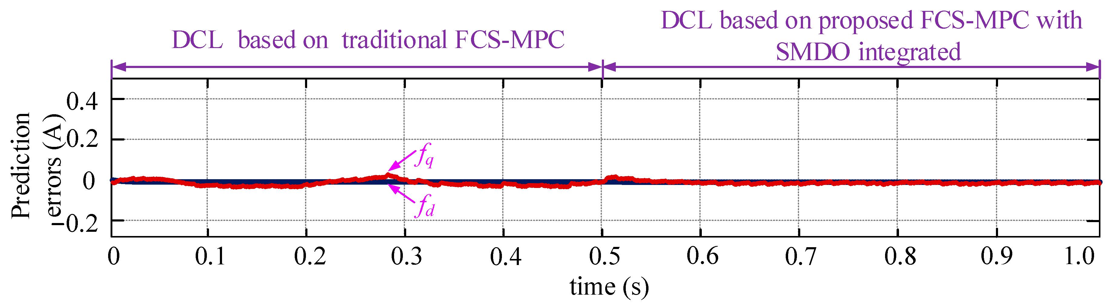
Assume that the measured filter inductance, line inductance, filter resistance, and line resistance used for the FCS-MPC controller are 4, 3, 0.5, and 0.3 times as large as the real values, respectively. Namely, Lf_mea = 2Lf = 0.36 H, Ll_mea = 3Ll = 0.3 mH, Rf_mea = 0.5Rf = 0.08 Ω, and Rl_mea = 0.3Rl = 0.36 Ω. Figure 13 and Figure 14 show the performance of the DCL strategy based on the traditional FCS-MPC and the DCL strategy based on the proposed FCS-MPC with SMDO integrated. Figure 15 shows the current prediction errors. Being different from condition a), the control performance in Figure 13 and Figure 14 is very similar. This happens because, when in this parameter mismatch condition, the prediction errors are pretty small (see Figure 15). It deserves to be mentioned that even the prediction errors are nearly zero, and the proposed technique is able to achieve voltage and frequency-errorless control without sacrificing the control performance.
5. Conclusions
This paper proposes a robust errorless-control-targeted technique based on FCS-MPC for a microgrid with uncertain electric vehicle energy storage systems, which works under the island mode. The main contributions and novelties are as follows:
- (1)
- A novel DCL control method is proposed, with each part of it detailed. In comparison with the traditional control strategies, such as droop control and VSG control, the proposed one aims to directly regulate the frequency, voltage, and currents rather than the power of the system. As for this strategy, droop coefficients are no longer needed, solving the problem that it is difficult to determine the droop coefficients of the microgrid with uncertain EV energy storage systems.
- (2)
- The impacts of the system parameter mismatch on the prediction accuracy of the FCS-MPC are analyzed explicitly, posing the necessity of developing the robust MPC controller.
- (3)
- SMDOs based on the hyperbolic function are developed to detect the d, q-axis disturbances, with their stability discussed innovatively. The detected disturbances are controlled to maintain at zero by using ADRs, generating voltage compensations used for modifying the PPM of the MPC controller, thus achieving the goal of disturbance impact elimination. Simulation results prove that the proposed strategies are effective.
As far as the proposed strategies in this research are concerned, there are several interesting problems that deserve future study. Firstly, in addition to the FCS-MPC controller, many advanced controllers, such as the variable structure control and future search algorithm, etc., can be adopted to achieve the DCL method, which might also be efficient. Secondly, although the stability of the proposed SMDO is analyzed, the stability of the whole closed-loop control strategy with the FCS-MPC and SMDO integrated is not addressed in this paper. Thirdly, a trial-and-error strategy is used to tune the parameters of the PI controllers used in the DCL control topology, which needs to be replaced by a theoretical analysis strategy. Fourthly, the simulation results show that there are small oscillations that are related to the load conditions in the currents of the proposed method. This is an interesting phenomenon, and it might be caused by more different reasons that need to be urgently explored.
Author Contributions
Supervision, Y.H., and Y.N.; writing—original draft, Y.L. All authors have read and agreed to the published version of the manuscript.
Funding
This research received no external funding.
Institutional Review Board Statement
Not applicable.
Informed Consent Statement
Not applicable.
Conflicts of Interest
The authors declare no conflict of interest.
Nomenclature
| n | Number of charging piles in one microgrid |
| c | Ratio of EVs working at V2G mode to the maximum number of EVs |
| tsu, t | Period of EVs working at V2G mode, time |
| Psu | Supporting power from EVs |
| ua,b,c, ia,b,c | Three-phase voltages and currents |
| Udc | Bus voltage |
| T1, T2, …, T6 | Transistors |
| D1, D2, …, D6 | Diodes |
| Rf, Lf, Cf, Rl, Ll | Filter and line resistances, inductances and capacitance |
| Rf_mea, Lf_mea, Rl_mea, Ll_mea | Measured filter and line resistances and inductances |
| ∆Rf, ∆Lf, ∆Rl, ∆Ll | Deviations of filter and line resistances and inductances |
| ea, eb, ec | Output voltage of the inverter |
| ed, eq | d, q-axis control voltages |
| ud, uq | d, q-axis voltages |
| id, iq | d, q-axis currents |
| id*, iq* | d, q-axis current references |
| u* | Voltage reference |
| φ | Phase angle |
| Frequency and voltage magnitude | |
| Pt, Pe, Q | Mechanical power and active power, reactive power in VSG control |
| ω, ωN, PN, QN, VN, fN | Angular frequency, nominal speed, power, voltage and frequency |
| kw, kv | Droop coefficients for frequency and voltage in VSG control |
| θ, V | Angle and voltage amplitude for control |
| J | Virtual inertia for VSG control |
| D | Virtual damping for VSG control |
| fd, fq | d, q-axis disturbances |
| cd, cq | d, q-axis voltage compensations |
| kF_p, kF_i | Proportional and integral factors for AFR |
| kV_p, kV_i | Proportional and integral factors for AVR |
| kd, kq | Gain factors of sliding mode observers |
| , | Estimated currents of SMDOs |
| , | Errors between estimated currents and real currents in SMDOs |
| Ts | Control period |
| m | Boundary-layer constant |
| S | Sliding mode surfaces |
| Ly | Lyapunov function |
| λ | The smallest allowable estimation error |
| imax | The maximum allowable current of the system |
References
- Wang, T.; O’Neill, D.; Kamath, H. Dynamic Control and Optimization of Distributed Energy Resources in a Microgrid. IEEE Trans. Smart Grid 2015, 6, 2884–2894. [Google Scholar] [CrossRef] [Green Version]
- Benhalima, S.; Miloud, R.; Chandra, A. Real-Time Implementation of Robust Control Strategies Based on Sliding Mode Control for Standalone Microgrids Supplying Non-Linear Loads. Energies 2018, 11, 2590. [Google Scholar] [CrossRef] [Green Version]
- Mueller, J.A.; Kimball, J.W. An Efficient Method of Determining Operating Points of Droop-Controlled Microgrids. IEEE Trans. Energy Convers. 2017, 32, 1432–1446. [Google Scholar] [CrossRef]
- Camacho, A.; Castilla, M.; Canziani, F.; Moreira, C.; Coelho, P.; Gomes, M.; Mercado, P.E. Performance Comparison of Grid-Faulty Control Schemes for Inverter-Based Industrial Microgrids. Energies 2017, 10, 2096. [Google Scholar] [CrossRef] [Green Version]
- Liu, C.; Chau, K.T.; Wu, D.; Gao, S. Opportunities and Challenges of Vehicle-to-Home, Vehicle-to-Vehicle, and Vehicle-to-Grid Technologies. Proc. IEEE 2013, 101, 2409–2427. [Google Scholar] [CrossRef] [Green Version]
- Ouramdane, O.; Elbouchikhi, E.; Amirat, Y.; Sedgh Gooya, E. Optimal Sizing and Energy Management of Microgrids with Vehicle-to-Grid Technology: A Critical Review and Future Trends. Energies 2021, 14, 4166. [Google Scholar] [CrossRef]
- Shuai, Z.; Mo, S.; Wang, J.; Shen, Z.J.; Tian, W.; Feng, Y. Droop control method for load share and voltage regulation in high-voltage microgrids. J. Mod. Power Syst. Clean Energy 2016, 4, 76–86. [Google Scholar] [CrossRef] [Green Version]
- Beck, H.P.; Hesse, R. Virtual Synchronous Machine. In Proceedings of the International Conference on Electrical Power Quality & Utilisation, Barcelona, Spain, 9–11 October 2007; pp. 1–6. [Google Scholar]
- Zhao, Y.; Guo, L. Dynamical Simulation of Laboratory MicroGrid. In Proceedings of the IEEE 2009 Asia-Pacific Power and Energy Engineering Conference (APPEEC), Wuhan, China, 28–30 March 2009; pp. 1–5. [Google Scholar]
- Deng, Y.; Tao, Y.; Chen, G.; Li, G.; He, X. Enhanced Power Flow Control for Grid-Connected Droop-Controlled Inverters with Improved Stability. IEEE Trans. Ind. Electron. 2017, 64, 5919–5929. [Google Scholar] [CrossRef]
- Ashabani, M.; Ibrahim-Mohamed, Y.; Mirsalim, M.; Aghashabani, M. Multivariable Droop Control of Synchronous Current Converters in Weak Grids/Microgrids with Decoupled dq-Axes Currents. IEEE Trans. Smart Grid 2015, 6, 1610–1620. [Google Scholar] [CrossRef]
- Gorijeevaram Reddy, P.K.; Dasarathan, S.; Krishnasamy, V. Investigation of Adaptive Droop Control Applied to Low-Voltage DC Microgrid. Energies 2021, 14, 5356. [Google Scholar] [CrossRef]
- Li, G.; Ma, F.; Luo, A.; He, Z.; Wu, W.; Wei, X.; Zhu, Z.; Guo, J. Virtual impedance-based virtual synchronous generator control for grid-connected inverter under the weak grid situations. IET Power Electron. 2018, 11, 2125–2132. [Google Scholar] [CrossRef]
- Wu, W.; Chen, Y.; Zhou, L.; Luo, A.; Zhou, X.; He, Z.; Yang, L.; Xie, Z.; Liu, J.; Zhang, M. Sequence Impedance Modeling and Stability Comparative Analysis of Voltage-Controlled VSGs and Current-Controlled VSGs. IEEE Trans. Ind. Electron. 2018, 66, 6460–6472. [Google Scholar] [CrossRef]
- Zhong, Q.; Weiss, G. Synchronverters: Inverters That Mimic Synchronous Generators. IEEE Trans. Ind. Electron. 2011, 58, 1259–1267. [Google Scholar] [CrossRef]
- Jin, N.; Pan, C.; Li, Y.; Hu, S.; Fang, J. Model Predictive Control for Virtual Synchronous Generator with Improved Vector Selection and Reconstructed Current. Energies 2020, 13, 5435. [Google Scholar] [CrossRef]
- Magdy, G.; Bakeer, A.; Nour, M.; Petlenkov, E. A New Virtual Synchronous Generator Design Based on the SMES System for Frequency Stability of Low-Inertia Power Grids. Energies 2020, 13, 5641. [Google Scholar] [CrossRef]
- Mo, O.; D’Arco, S.; Suul, J.A. Evaluation of Virtual Synchronous Machines with Dynamic or Quasi-Stationary Machine Models. IEEE Tran. Ind. Electron. 2017, 64, 5952–5962. [Google Scholar] [CrossRef] [Green Version]
- D’Arco, S.; Suul, J.A. Equivalence of Virtual Synchronous Machines and Frequency-Droops for Converter-Based MicroGrids. IEEE Trans. Smart Grid 2014, 5, 394–395. [Google Scholar] [CrossRef]
- Li, B.; Li, Q.; Wang, Y.; Wen, W.; Li, B.; Xu, L. A Novel Method to Determine Droop Coefficients of DC Voltage Control for VSC-MTDC System. IEEE Trans. Power Deliv. 2020, 35, 2196–2211. [Google Scholar] [CrossRef]
- Pavan Kumar, Y.V.; Bhimasingu, R. Modern Control Methods for Adaptive Droop Coefficients’ Design. In Microgrid: Operation, Control, Monitoring and Protection; Springer: Singapore, 2020; pp. 111–148. [Google Scholar]
- Saleh-Ahmadi, A.; Moattari, M.; Gahedi, A.; Pouresmaeil, E. Droop Method Development for Microgrids Control Considering Higher Order Sliding Mode Control Approach and Feeder Impedance Variation. Appl. Sci. 2021, 11, 967. [Google Scholar] [CrossRef]
- Yogarathinam, A.; Chaudhuri, N.R. Stability-Constrained Adaptive Droop for Power Sharing in AC-MTDC Grids. IEEE Trans. Power Syst. 2019, 34, 1955–1965. [Google Scholar] [CrossRef]
- Wang, R.; Chen, L.; Zheng, T.; Mei, S. VSG-based adaptive droop control for frequency and active power regulation in the MTDC system. CSEE J. Power Energy Syst. 2017, 3, 260–268. [Google Scholar] [CrossRef]
- Baudoin, S.; Vechiu, I.; Camblong, H. A review of voltage and frequency control strategies for islanded microgrid. In Proceedings of the 2012 16th International Conference on System Theory, Control and Computing (ICSTCC), Sinaia, Romania, 12–14 October 2012; pp. 1–5. [Google Scholar]
- Kos, T.; Huba, M.; Vrančić, D. Parametric and Nonparametric PI Controller Tuning Method for Integrating Processes Based on Magnitude Optimum. Appl. Sci. 2020, 10, 1443. [Google Scholar] [CrossRef] [Green Version]
- Leal, I.S.; Abeykoon, C.; Perera, Y.S. Design, Simulation, Analysis and Optimization of PID and Fuzzy Based Control Systems for a Quadcopter. Electronics 2021, 10, 2218. [Google Scholar] [CrossRef]
- Simmini, F.; Caldognetto, T.; Bruschetta, M.; Mion, E.; Carli, R. Model Predictive Control for Efficient Management of Energy Resources in Smart Buildings. Energies 2021, 14, 5592. [Google Scholar] [CrossRef]
- Elsisi, M.; Abeoelela, M.; Soliman, M.; Mansor, W. Design of Optimal Model Predictive Controller for LFC of Nonlinear Multi-area Power System with Energy Storage Devices. Electr. Power Compon. Syst. 2018, 46, 1300–1311. [Google Scholar] [CrossRef]
- Valverde, L.; Bordons, C.; Rosa, F. Power Management using Model Predictive Control in a Hydrogen-based Microgrid. In Proceedings of the IECON 2012—38th Annual Conference on IEEE Industrial Electronics Society, Montreal, QC, Canada, 25–28 October 2012; pp. 5669–5676. [Google Scholar]
- Elsisi, M. New Variable Structure Control based on Different Meta-Heuristics Algorithms for Frequency Regulation Considering Nonlinearities Effects. Intern. Trans. Electr. Energy Syst. 2020, 30, 12428. [Google Scholar] [CrossRef]
- Elsisi, M.; Soliman, M.; Aboelela, M.A.S.; Mansour, W. GSA-Based Design of Dual Proportional Integral Load Frequency Controllers for Nonlinear Hydrothermal Power System. World Acad. Sci. Eng. Technol. 2015, 9, 1–7. [Google Scholar]
- Elsisi, M. Future Search Algorithm for Optimization. Evol. Intell. 2019, 12, 21–31. [Google Scholar] [CrossRef]
- Han, Y.; Gong, C.; Yan, L.; Wen, H.; Wang, Y.; Shen, K. Multiobjective Finite Control Set Model Predictive Control Using Novel Delay Compensation Technique for PMSM. IEEE Trans. Power Electron. 2020, 35, 11193–11204. [Google Scholar] [CrossRef]
- Valibeygi, A.; Habib, A.H.; de Callafon, R.A. Robust Power Scheduling for Microgrids with Uncertainty in Renewable Energy Generation. In Proceedings of the 2019 IEEE Power & Energy Society Innovative Smart Grid Technologies Conference (ISGT), Gramado, Brazil, 18–21 February 2019; pp. 1–5. [Google Scholar]
- Davari, M.; Mohamed, Y.A.I. Robust Multi-Objective Control of VSC-Based DC-Voltage Power Port in Hybrid AC/DC Multi-Terminal Micro-Grids. IEEE Trans. Smart Grid 2013, 4, 1597–1612. [Google Scholar] [CrossRef]
- Aryani, D.R.; Song, H. Coordination Control Strategy for AC/DC Hybrid Microgrids in Stand-Alone Mode. Energies 2016, 9, 469. [Google Scholar] [CrossRef]
- Shi, X.; Lan, T.; Hu, J.P. PID controller tuning using optimization based on gradient-immune algorithm. In Proceedings of the 2012 International Symposium on Instrumentation & Measurement, Sensor Network and Automation (IMSNA), Sanya, China, 25–28 August 2012; pp. 173–175. [Google Scholar]
- Gao, J.; Gong, C.; Li, W.; Liu, J. Novel Compensation Strategy for Calculation Delay of Finite Control Set Model Predictive Current Control in PMSM. IEEE Trans. Ind. Electron. 2019, 67, 5816–5819. [Google Scholar] [CrossRef]
- Hennane, Y.; Berdai, A.; Martin, J.-P.; Pierfederici, S.; Meibody-Tabar, F. New Decentralized Control of Mesh AC Microgrids: Study, Stability, and Robustness Analysis. Sustainability 2021, 13, 2243. [Google Scholar] [CrossRef]
- Krueger, H.; Cruden, A. Integration of electric vehicle user charging preferences into Vehicle-to-Grid aggregator controls. Energy Rep. 2020, 6, 86–95. [Google Scholar] [CrossRef]
- Gong, C.; Hu, Y.; Gao, J.; Wang, Y.; Yan, L. An Improved Delay-Suppressed Sliding-Mode Observer for Sensorless Vector-Controlled PMSM. IEEE Trans. Ind. Electron. 2020, 67, 5913–5923. [Google Scholar] [CrossRef]
- Liang, Y.; He, Y.; Niu, Y. Microgrid Frequency Fluctuation Attenuation Using Improved Fuzzy Adaptive Damping-Based VSG Considering Dynamics and Allowable Deviation. Energies 2020, 13, 4885. [Google Scholar] [CrossRef]
Figure 1.
Structure of VSG control-based microgrid.
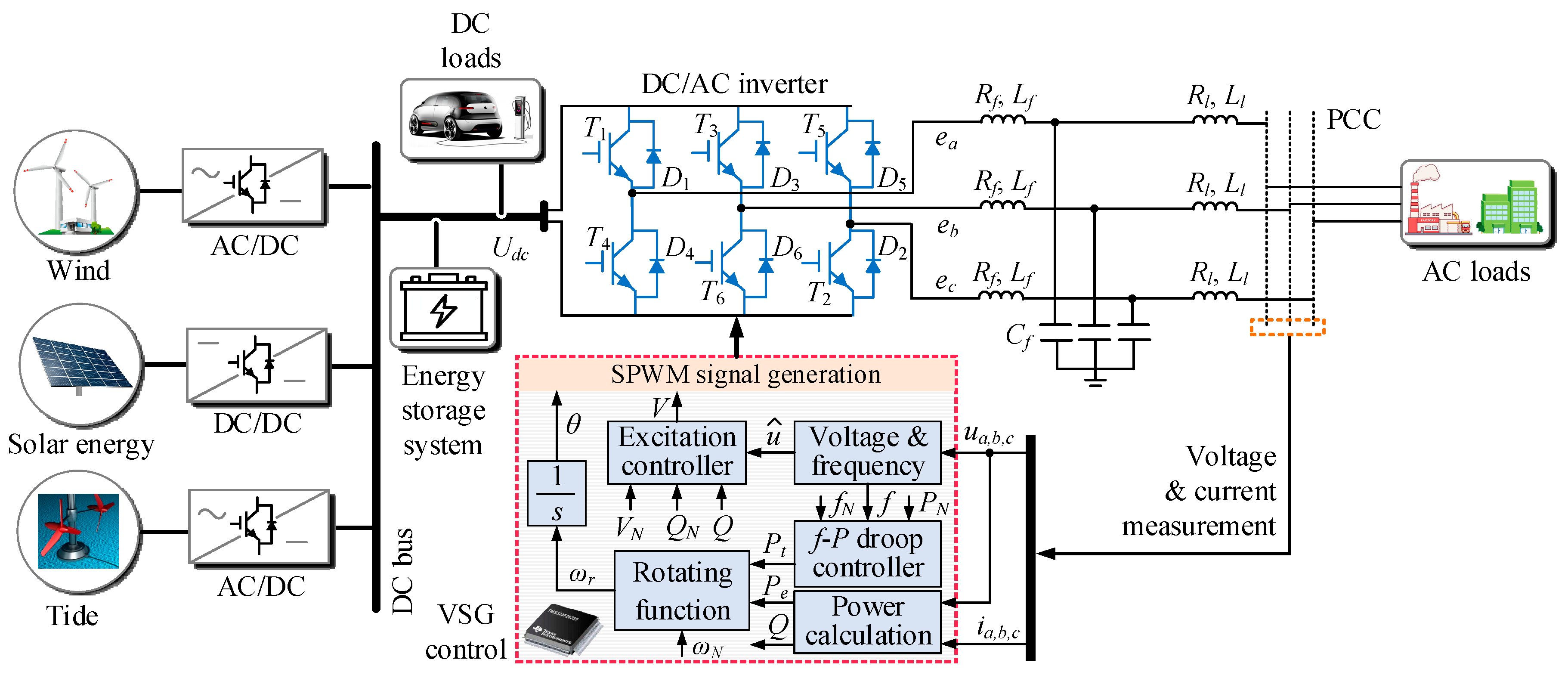
Figure 2.
Structure of proposed DCL control strategy for microgrid working at island mode.

Figure 3.
Three-phase PLL for frequency, phase angle, and voltage detection.
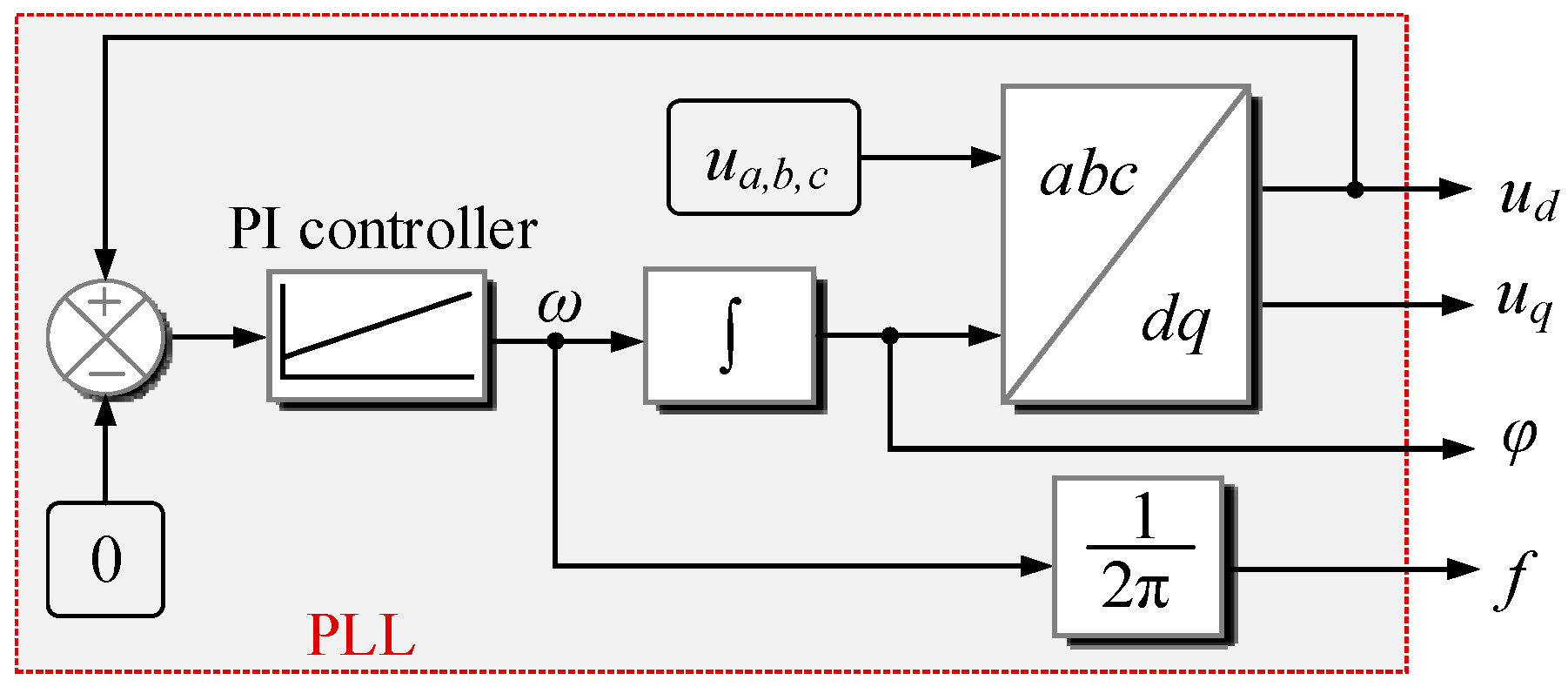
Figure 4.
Relationship between the current estimation errors and the parameter variations. (a) Relationship between d-axis current estimation errors and ∆Rf, ∆Lf (∆Rl = ∆Ll = 0). (b) Relationship between d-axis current estimation errors and ∆Rl, ∆Ll (∆Rf = ∆Lf = 0). (c) Relationship between q-axis current estimation errors and ∆Rf, ∆Lf (∆Rl = ∆Ll = 0). (d) Relationship between q-axis current estimation errors and ∆Rl, ∆Ll (∆Rf = ∆Lf = 0).

Figure 5.
Simulation setup for the proposed errorless-control-targeted technique based on the robust MPC.
Figure 5.
Simulation setup for the proposed errorless-control-targeted technique based on the robust MPC.
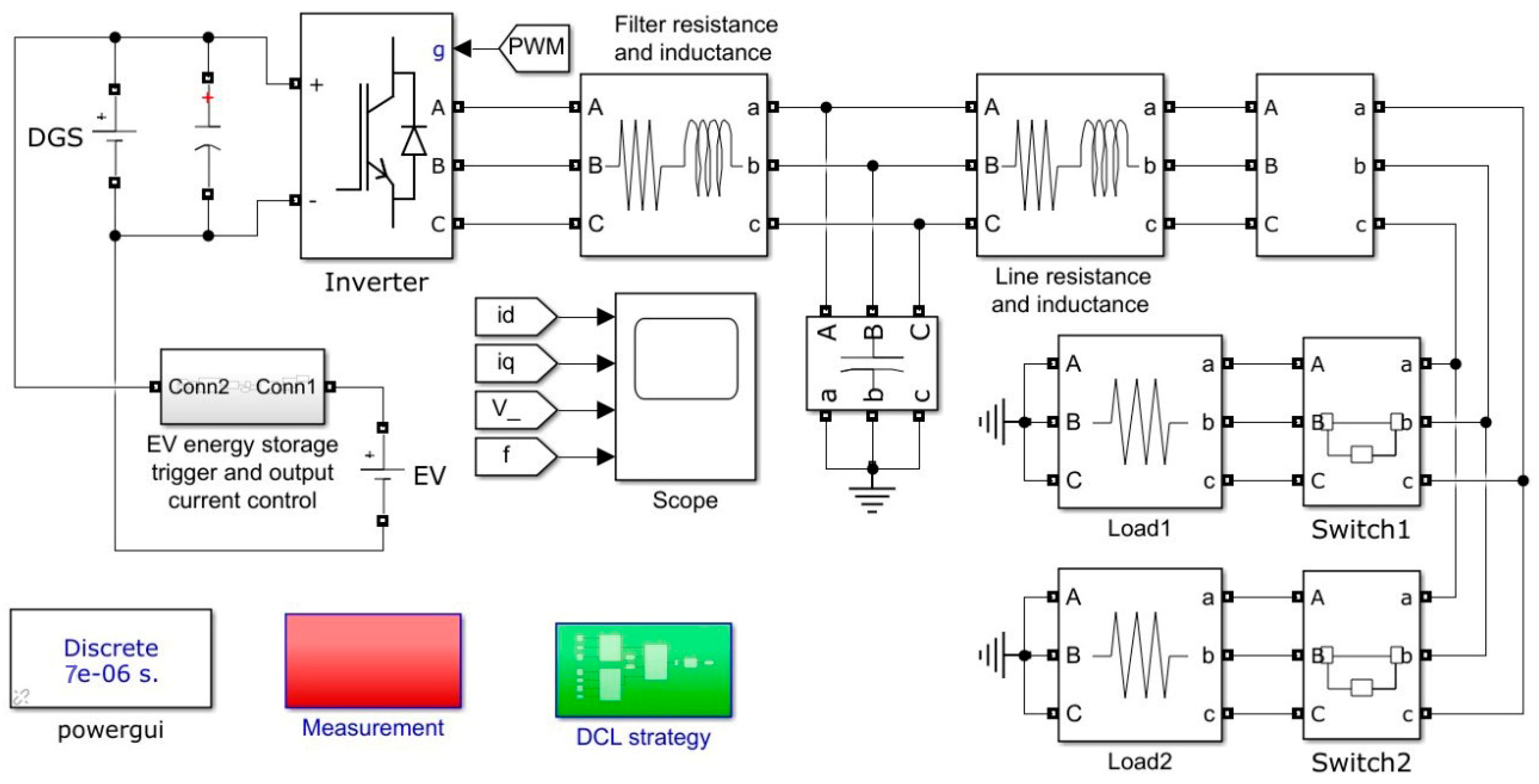
Figure 6.
Control performance of the traditional VSG method without parameter mismatch and EV uncertainties considered.
Figure 6.
Control performance of the traditional VSG method without parameter mismatch and EV uncertainties considered.

Figure 7.
Control performance of the improved VSG method without parameter mismatch and EV uncertainties considered.
Figure 7.
Control performance of the improved VSG method without parameter mismatch and EV uncertainties considered.
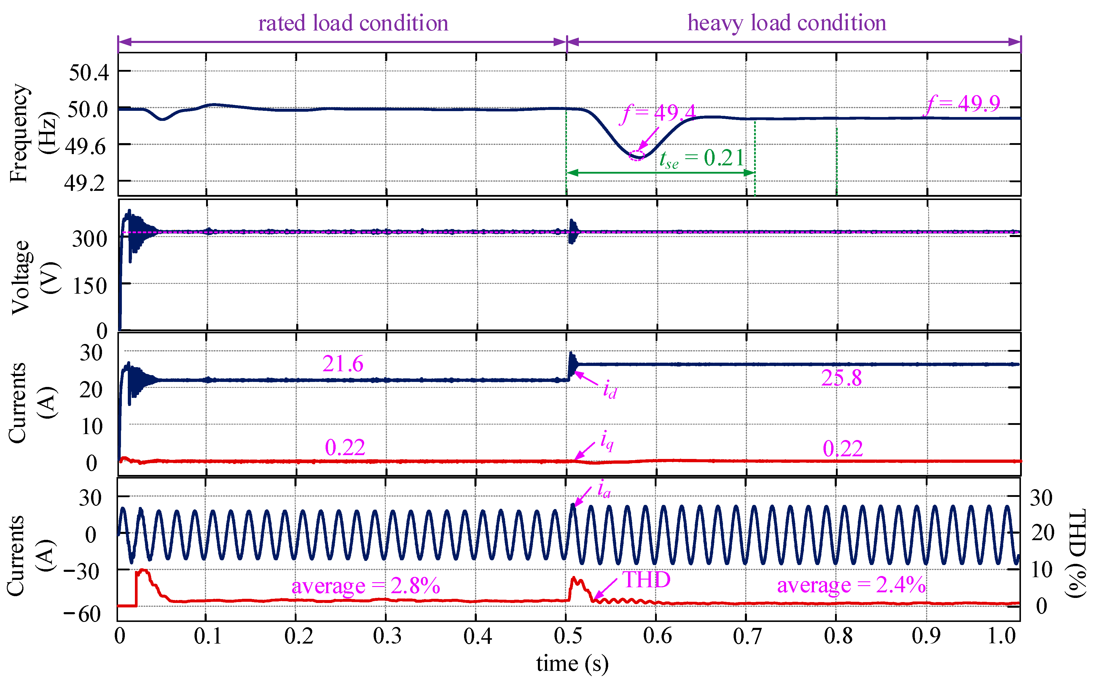
Figure 8.
Control performance of the proposed DCL method without parameter mismatch and EV uncertainties considered.
Figure 8.
Control performance of the proposed DCL method without parameter mismatch and EV uncertainties considered.
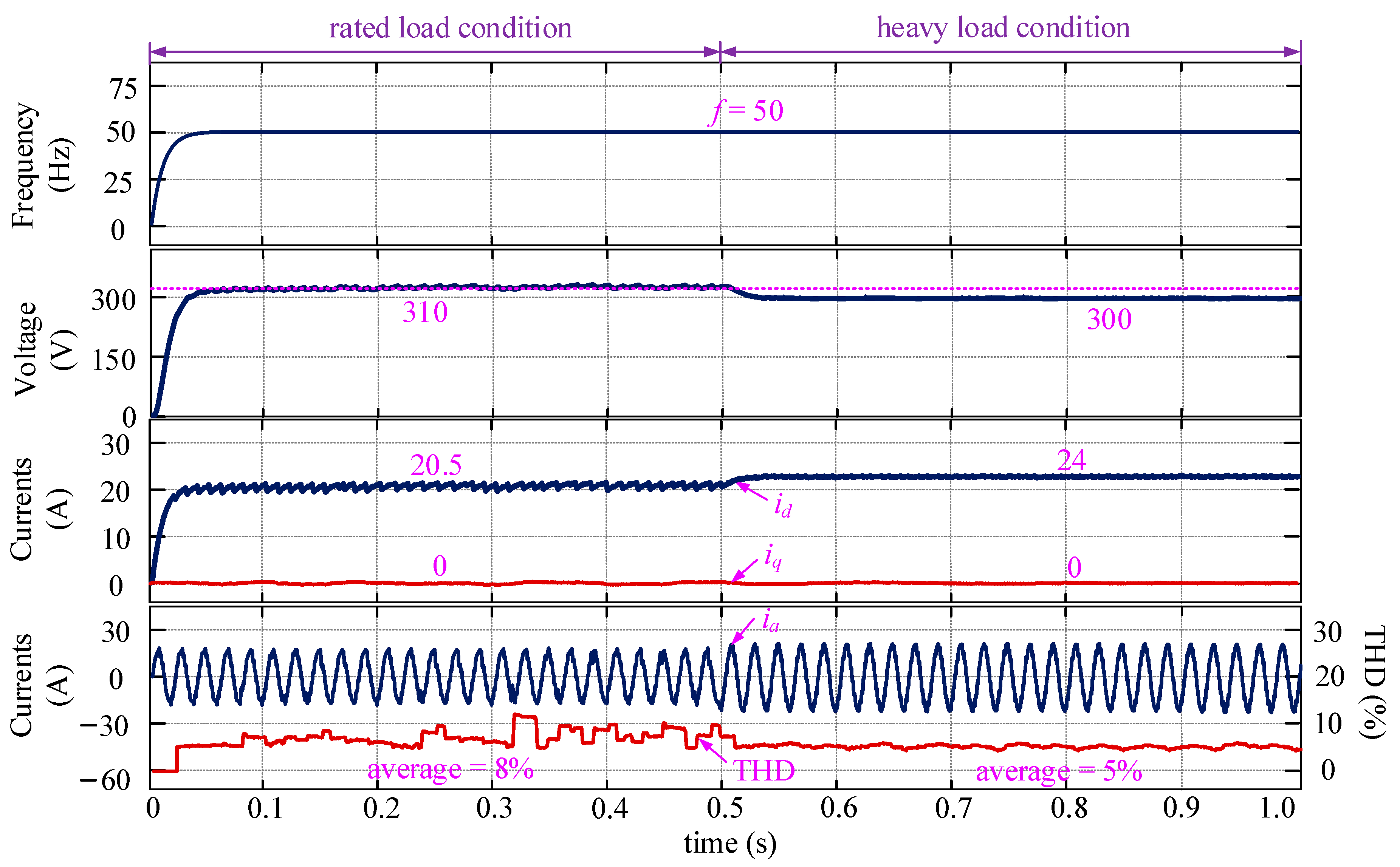
Figure 9.
Control performance of the proposed DCL method with EV uncertainties considered.
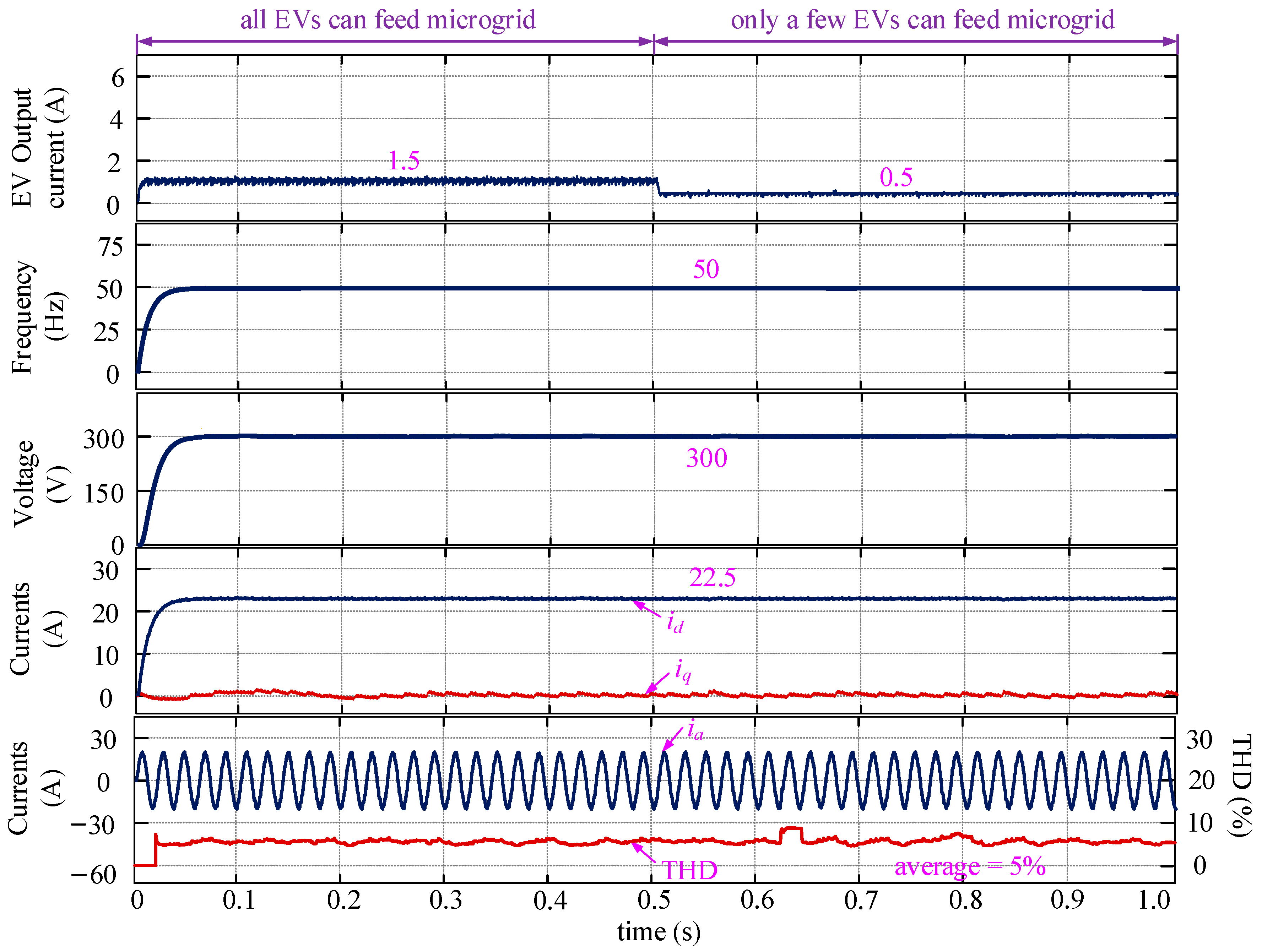
Figure 10.
Control performance of the proposed DCL method with parameter mismatch considered (the SMDO does not work, Lf_mea = 0.2Lf, Ll_mea = 0.2Ll, Rf_mea = 2Rf, Rl_mea = 2Rl).
Figure 10.
Control performance of the proposed DCL method with parameter mismatch considered (the SMDO does not work, Lf_mea = 0.2Lf, Ll_mea = 0.2Ll, Rf_mea = 2Rf, Rl_mea = 2Rl).
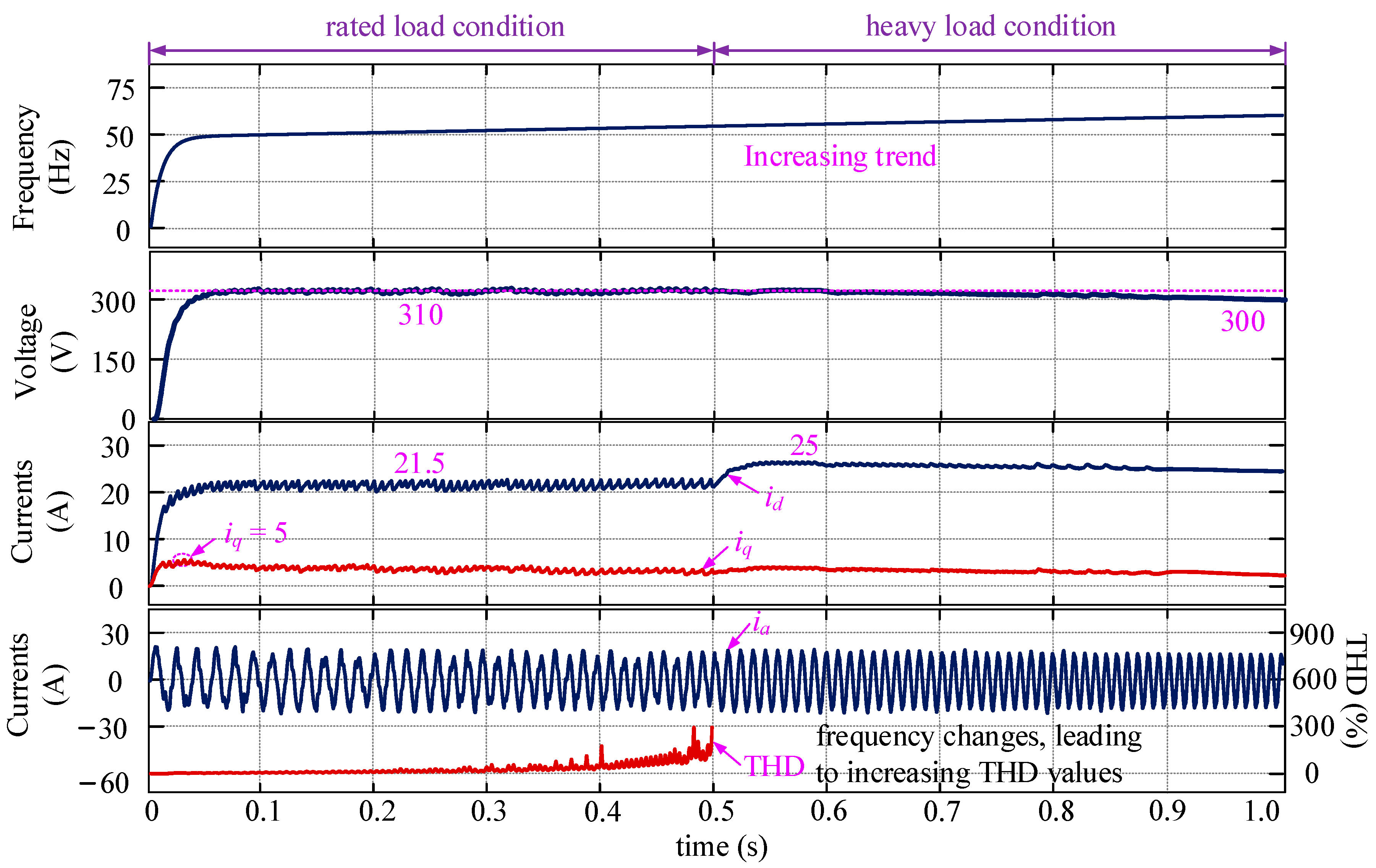
Figure 11.
Control performance of the proposed DCL method with parameter mismatch considered (the SMDO works, Lf_mea = 0.2Lf, Ll_mea = 0.2Ll, Rf_mea = 2Rf, Rl_mea = 2Rl).
Figure 11.
Control performance of the proposed DCL method with parameter mismatch considered (the SMDO works, Lf_mea = 0.2Lf, Ll_mea = 0.2Ll, Rf_mea = 2Rf, Rl_mea = 2Rl).
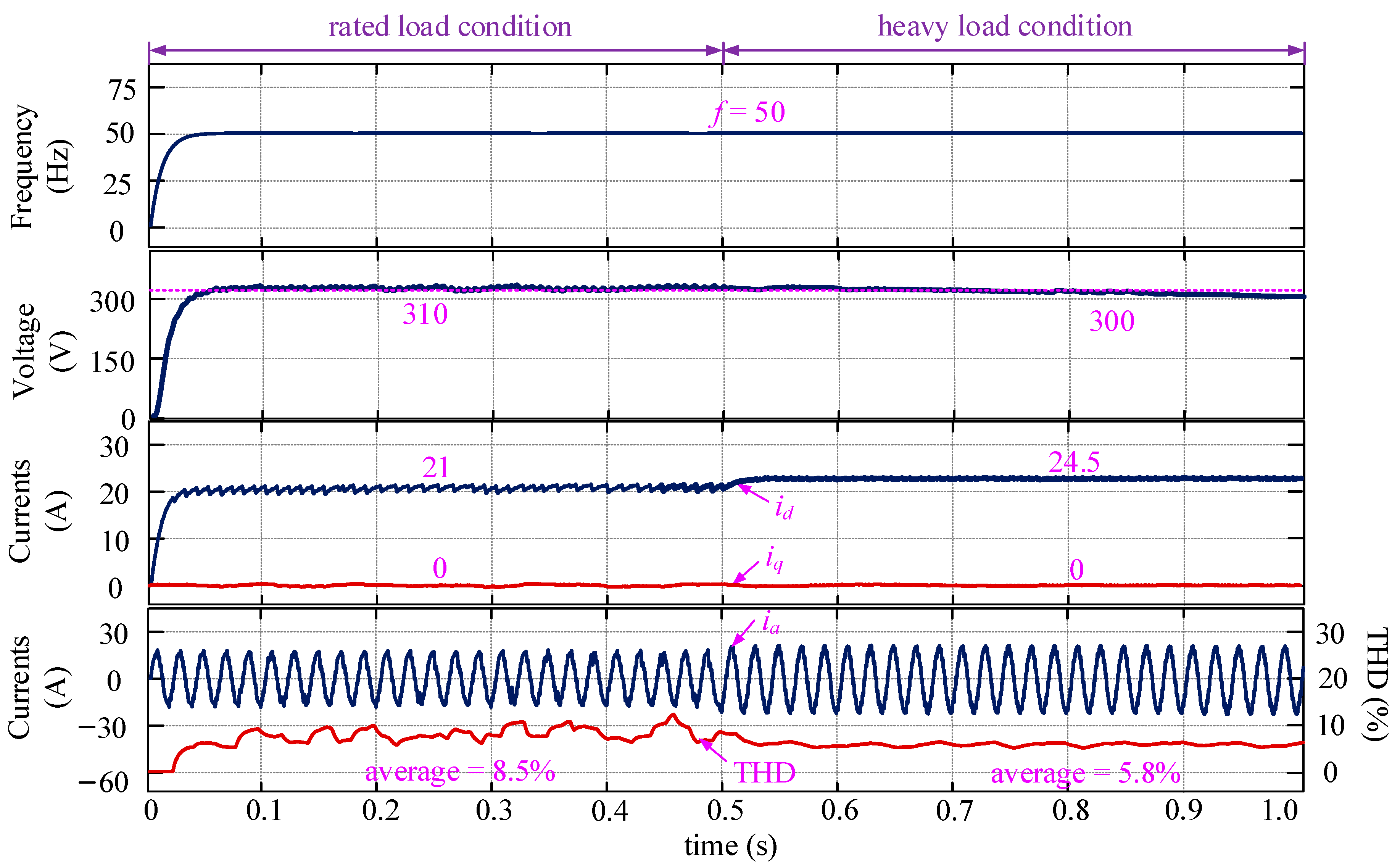
Figure 12.
Comparative results of the current prediction errors before and after the proposed SMDO-based MPC method is employed (Lf_mea = 0.2Lf, Ll_mea = 0.2Ll, Rf_mea = 2Rf, Rl_mea = 2Rl).
Figure 12.
Comparative results of the current prediction errors before and after the proposed SMDO-based MPC method is employed (Lf_mea = 0.2Lf, Ll_mea = 0.2Ll, Rf_mea = 2Rf, Rl_mea = 2Rl).
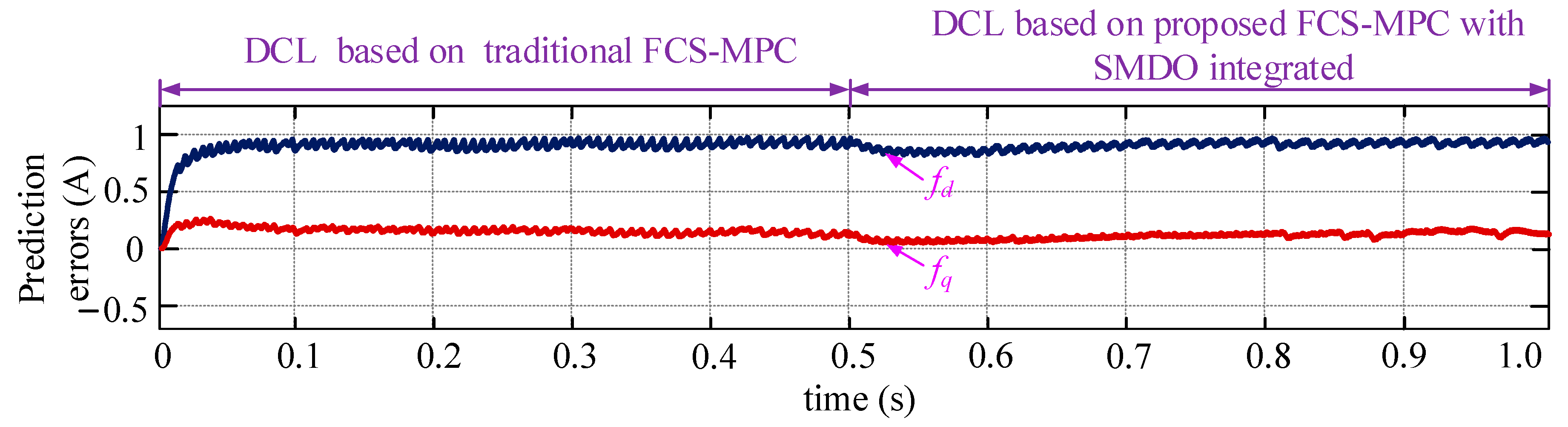
Figure 13.
Control performance of the proposed DCL method with parameter mismatch considered (the SMDO does not work, Lf_mea = 4Lf, Ll_mea = 3Ll, Rf_mea = 0.5Rf, Rl_mea = 0.3Rl).
Figure 13.
Control performance of the proposed DCL method with parameter mismatch considered (the SMDO does not work, Lf_mea = 4Lf, Ll_mea = 3Ll, Rf_mea = 0.5Rf, Rl_mea = 0.3Rl).

Figure 14.
Control performance of the proposed DCL method with parameter mismatch considered (the SMDO works, Lf_mea = 4Lf, Ll_mea = 3Ll, Rf_mea = 0.5Rf, Rl_mea = 0.3Rl).
Figure 14.
Control performance of the proposed DCL method with parameter mismatch considered (the SMDO works, Lf_mea = 4Lf, Ll_mea = 3Ll, Rf_mea = 0.5Rf, Rl_mea = 0.3Rl).

Figure 15.
Comparative results of the current prediction errors before and after the proposed SMDO-based MPC method are employed (Lf_mea = 4Lf, Ll_mea = 3Ll, Rf_mea = 0.5Rf, Rl_mea = 0.3Rl).
Figure 15.
Comparative results of the current prediction errors before and after the proposed SMDO-based MPC method are employed (Lf_mea = 4Lf, Ll_mea = 3Ll, Rf_mea = 0.5Rf, Rl_mea = 0.3Rl).

Table 1.
Comparisons of traditional VSG strategy and proposed DCL strategy.
| Methods | Traditional VSG Strategy | Proposed DCL Strategy | |
|---|---|---|---|
| Differences | |||
| Regulated variables | active power and inactive power | frequency and voltage | |
| Voltage regulation | open-loop voltage control | voltage-errorless feedback control | |
| Frequency regulation | frequency-feedback-based power regulation | frequency-errorless feedback control | |
| Current control | X | MPC-based current regulation | |
| PWM signal generation | SPWM signal generation | optimal voltage vector selection-based PWM signal generation | |
Table 2.
Main parameters of the microgrid.
| Variable | Value | Unit |
|---|---|---|
| PN | 10 | kVA |
| UN | 310 | V |
| fN | 50 | Hz |
| UDC | 800 | V |
| Lf | 0.18 | H |
| Rf | 0.16 | Ω |
| Cf | 10 | μF |
| Ll | 0.1 | mH |
| Rl | 1.2 | Ω |
| Ts | 0.001 | s |
| kω | −2π × 10−4 | - |
| kv | 0.0001 | - |
Publisher’s Note: MDPI stays neutral with regard to jurisdictional claims in published maps and institutional affiliations. |
© 2022 by the authors. Licensee MDPI, Basel, Switzerland. This article is an open access article distributed under the terms and conditions of the Creative Commons Attribution (CC BY) license (https://creativecommons.org/licenses/by/4.0/).
Share and Cite
MDPI and ACS Style
Liang, Y.; He, Y.; Niu, Y. Robust Errorless-Control-Targeted Technique Based on MPC for Microgrid with Uncertain Electric Vehicle Energy Storage Systems. Energies 2022, 15, 1398. https://doi.org/10.3390/en15041398
AMA Style
Liang Y, He Y, Niu Y. Robust Errorless-Control-Targeted Technique Based on MPC for Microgrid with Uncertain Electric Vehicle Energy Storage Systems. Energies. 2022; 15(4):1398. https://doi.org/10.3390/en15041398
Chicago/Turabian StyleLiang, Yalin, Yuyao He, and Yun Niu. 2022. "Robust Errorless-Control-Targeted Technique Based on MPC for Microgrid with Uncertain Electric Vehicle Energy Storage Systems" Energies 15, no. 4: 1398. https://doi.org/10.3390/en15041398
Note that from the first issue of 2016, this journal uses article numbers instead of page numbers. See further details here.