Abstract
Friction and heat generated in conventional bearings impose a limit on maximum design speed in electrical machines. Superconducting bearings offer the potential for low loss, simplified, and passively stable bearings that can overcome the speed limit and operate at high loads. Although such bearings are contactless and seem to be loss free, AC loss mainly caused by magnetic field inhomogeneity gradually slows down the rotating body. This loss, whose mechanism has not been fully explored, is measured through spin-down tests where the rotational speed of the spinning rotor is measured as a function of time. However, there are some challenges in performing a reliable spin-down test. In this paper, we discuss these challenges as well as the engineering of an experimental test rig that enables us to spin-up, release, and recapture the levitated permanent magnet. We also discuss the specifications of the driving mechanism including the self-aligning coupling, which accommodates permanent magnets of different sizes. Initial test results at 6600 rpm are discussed and further technical improvements to the test rig suggested. This rig will be used as a key tool to explore the AC loss mechanism and inform the design of bearings for high-speed superconducting machines.
1. Introduction
The output power of an electrical machine is proportional to both rotational frequency and rotor excitation field [1]. The friction and heat generated by conventional bearings limit the design speed of any electrical machine. Active magnetic bearings [2,3,4] and superconducting magnetic bearings [5,6,7] have been widely investigated as possible solutions to overcome this speed barrier.
According to Earnshaw’s theorem, permanent magnet–permanent magnet (PM–PM) interactions are statically unstable [8,9]. Therefore, magnetic bearings require active position controllers to maintain the stability of the system. This can add complexity to the bearing system design. In contrast, superconducting magnetic bearings offer passive stable levitation/suspension through th flux pinning feature of type-II superconductors [5].
As superconducting bearings are contactless, they seem to be loss free. However, magnetic field inhomogeneity is said to be the main source of AC loss in these bearings [5,10,11,12]. The coefficient of friction (COF), which is obtained from spin-down tests, has been used as a reliable parameter to calculate AC loss and as a figure of merit when comparing different bearing types [13,14,15,16,17,18,19,20,21]. The main challenge in performing spin-down tests is to engineer a driving system to accelerate and decelerate the levitating PM. Gas jets [10,22], electrical motors [10,23,24,25], a three-phase handmade brushless motor [26], eddy current clutches [15,23,27,28,29,30], and magnetic gears [31] have been employed to accelerate the rotating part of superconducting bearings. These methods are associated with complex coupling structures, loss creation, limited maximum speed, and lack of precision when it comes to speed control.
In this paper, we discuss the design, manufacture, and experimental evaluation of a test setup allowing acceleration, release, and recapture of a levitated PM. This experimental setup will be used to measure AC loss caused by magnetic field inhomogeneity in superconducting magnetic bearings.
2. Materials and Methods
The main purpose of this test rig is to perform spin-down experiments to measure AC loss created in a superconducting magnetic levitation thrust bearing. This test rig consists of three main parts, namely the driving system, vacuum and cooling systems, and sensors and measurement equipment.
2.1. Driving System
The main challenge in this rig was devising a method to spin up the PM to 30,000 rpm, release it, then capture it again. A high-speed brushless DC motor, whose characteristics are shown in Table 1, was used to spin the PM. The motor was a ECXSP22L BL KL A STEC 48V model supplied by MaxonMotor [32]. It is controlled by a ESCON 50/5 controller. Because the motor operates in a vacuum where heat dissipation through convection is not possible, the motor was fixed in an aluminium heat sink. The heat sink with the motor inside was mounted on a vertical linear displacement stage.

Table 1.
Motor parameters.
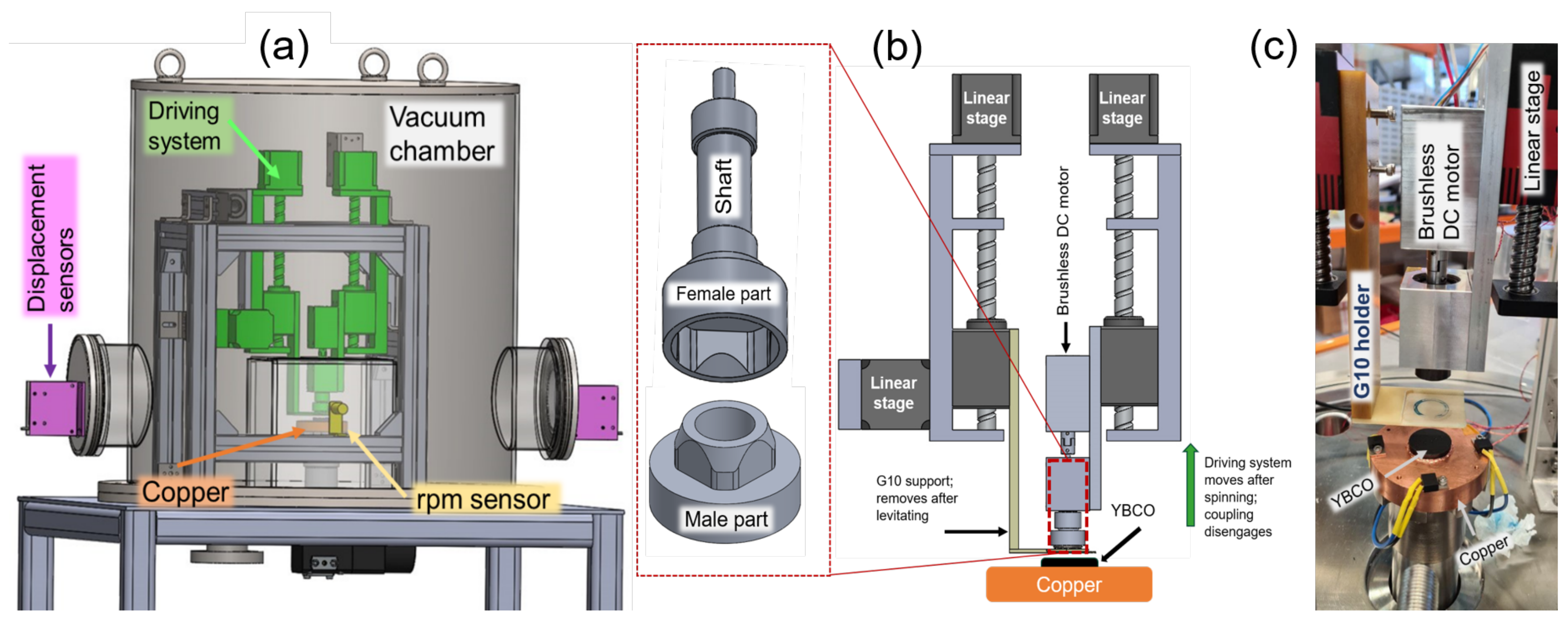
A power transmission mechanism consisting of two coupled parts was designed and built at Robinson Research Institute to transfer power from the motor shaft, which was 4 mm in diameter to the PM, which can be 20, 17, or 15 mm in diameter. The first part acted as a holder for the PM and included the male side of the coupling. It was comprised of a hollow cylinder inside which the PM was bonded. The inner and outer diameters of the cylinder were 20 and 30 mm, respectively. Two aluminium sleeves, 17 and 15 mm in inner diameter and 20 mm in outer diameter, allowed different-sized PMs to be installed. The top surface of the cylinder was machined to form a P4C-like polygon based on DIN 32712. At the upper edge of the polygon, a chamfer with an aspect ratio of 1:1, and dimensions of 3 mm × 45° was machined. This chamfer helped self-centring during the coupling and decoupling processes. More effective chamfers could be machined; however, these characteristics were chosen due to machining equipment limitations. The second part consisted of a 65-mm long aluminium shaft. The bottom of the shaft was a cut-through P4C-like polygon with the same chamfer characteristics as the male part, and served as the female side of the PM coupling. This aluminium shaft was connected to the motor shaft by a jaw-type coupling. The aluminium shaft was fixed and supported by two ceramic ball bearings embedded at two ends of an aluminium box. This box improved the bearing’s axial alignment and enhanced heat dissipation. All parts were made of aluminium because it is light-weight and easy to machine. Moreover, as it is not ferromagnetic, it does not interact with the PM or the motor. Figure 1 shows drawings and a photo of the test rig and driving mechanism.
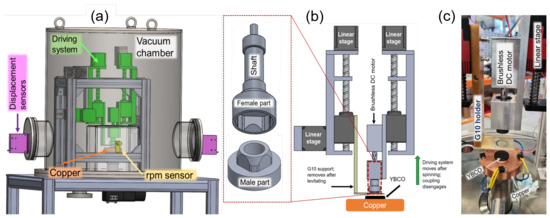
Figure 1.
Schematic demonstration of the test rig (a), the driving system (b), and a photo of the driving system (c).
A shielding box made of transparent polycarbonate was used to protect sensitive parts, such as sensors and cryostat windows, from being hit by the PM in the case of an unexpected unstable rotation. This box covered the PM, coupling systems, and the superconducting bulk.
A thin G10 support mounted on a second vertical linear displacement stage was provided to adjust the cooling height of the PM above the superconductor surface. This support, together with the linear stage, were mounted on another lateral linear stage, which could move the support aside after reaching the desired temperature. All linear stages were controlled by an Arduino-based controller. The entire driving system was mounted on an aluminium frame, whose parts could be removed and changed into a new configuration.
2.2. Vacuum and Cooling Systems
The whole experimental test rig was housed inside a cylindrical stainless steel vacuum chamber, which was 600 mm in both diameter and length. Two windows were machined on the side wall of the chamber, allowing non-vacuum rated displacement sensors to be installed outside the vacuum environment. The base plate of the chamber allowed the cold head of the cryocooler and electronic connections to be fed through from below.
A two-stage Edwards T-Station 85 [33] was used to evacuate the chamber. The T-Station 85 seamlessly combined an nEXT85H turbomolecular pump with a dry diaphragm backing pump (XDD1) and a simple controller. This system was capable of maintaining the vacuum at mbar inside the chamber, thereby ensuring the stability of the cryogenic environment.
The superconducting bulk was a melt-textured YBaCuO disc; 28 mm in diameter and 10 mm in thickness. The YBCO disc, which forms the stator part of the bearing, was partially recessed into a copper plate mounted on the Coolstar 0/40 cold head of a GM cryocooler supplied by Oxford Cryosystems [34].
2.3. Sensors and Measurement Equipment
In this test rig, we were interested in measuring the vibrations of the PM during spin-down measurements especially when it passed through its resonance frequencies. For this purpose, a Keyence IB-30 laser displacement sensor [35] was employed. A Monarch Instrument remote optical sensor model ROS-W [36] mounted on the setup frame measured the rotational frequency of the PM. This sensor is capable of measuring speeds up to 250 krpm, which is well above our maximum desired frequency. A small plug and play camera capable of 60 frames per second and an associated light source was installed inside the vacuum chamber to monitor and record the experiment process. A S950-SM silicon diode sensor [37] mounted on the copper plate was used as the temperature reference. The temperature of the motor and ceramic bearings was measured by PT100 sensors. The PT100 sensors were calibrated against the standard curve of the diode sensor by mounting them together on a copper plate during a cool-down/warm-up measurement sequence. The temperature of the superconducting puck was controlled by a Cryocon-26 controller [38].
To characterize the field from the PM we designed and built a benchtop setup (Figure 2) to map the magnetic field in a 3D volume. The magnetic field was measured by a Hall sensor supplied by [39]. The sensor was mounted on the tip of a cylinder made of G10. The 3D motion with a resolution of mm was realized by linear stages controlled by an controller supplied by [40].

Figure 2.
The magnetic field measurement setup (a), and the magnetic field of the 17 mm PM at mm distance from its surface (b).
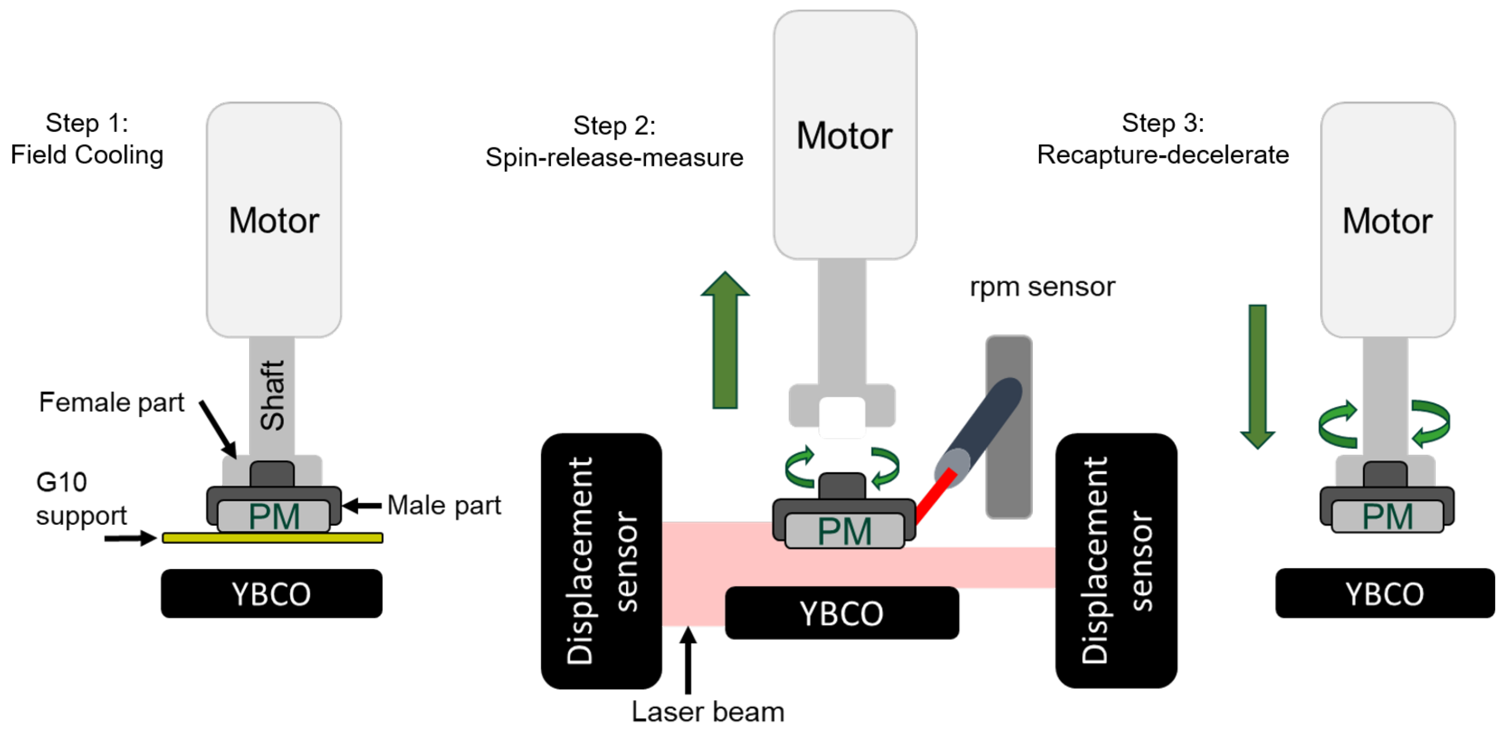
Figure 3 shows the planned experiment steps. First, the PM was placed on the G10 support and was coupled to the shaft. The male and female parts of the PM coupling slip and mate because of their chamfer structures. Then, both vertical linear stages moved the G10 support and the driving system towards the YBCO bulk at a common velocity to the desired cooling height. Next, the YBCO bulk was cooled into the superconducting state with the PM in its vicinity (field-cooled (FC) condition). The support was moved down and then aside. Next, the speed of the motor was gradually increased to the target speed. After a few seconds, the motor and the shaft were moved upward, releasing the PM to be freely levitated and rotating above the superconductor.

Figure 3.
Spin-down experiment process.
The rotational speed of the PM will decrease due to AC loss. During the spin-down period, rotational speed, vibrations, and temperature were measured and recorded simultaneously.
Once the experiment was complete and the PM has stopped, the G10 support was moved between the PM and the YBCO bulk. It is intended that this coupling mechanism allows the user to change the speed of the PM or to stop it at a certain speed. To do this, the motor speed was set just below that of the spinning PM, then the coupling mechanism was moved downward slowly. When male and female parts of the coupling mate, the PM rotation speed can be decreased or increased by changing the motor speed. The whole experimental sequence can be repeated for PMs of different sizes by using matching sleeves to seat them into the male part.
3. Results and Discussion
The z-component of the magnetic field from a PM 17 mm in diameter and 10 mm thick was mapped over a 3D volume at room temperature. Figure 2 shows the magnetic flux density B at a distance of mm from the PM surface over an area of 27 mm × 27 mm in mm steps. From this, we determine that the azimuthal inhomogeneity of the magnetic field experienced by the YBCO puck during the spin-down experiment was 38 mT. The field magnitude crossing any Al parts was less than 5 mT and would have a dynamic less than mT/s, if homogeneity is greater than . The contribution of eddy currents induced in the motor parts can be neglected because the motor is used as an initial driving system that is then retracted.
According to critical state model, the hysteresis loss per cycle per unit volume is given by [41]:
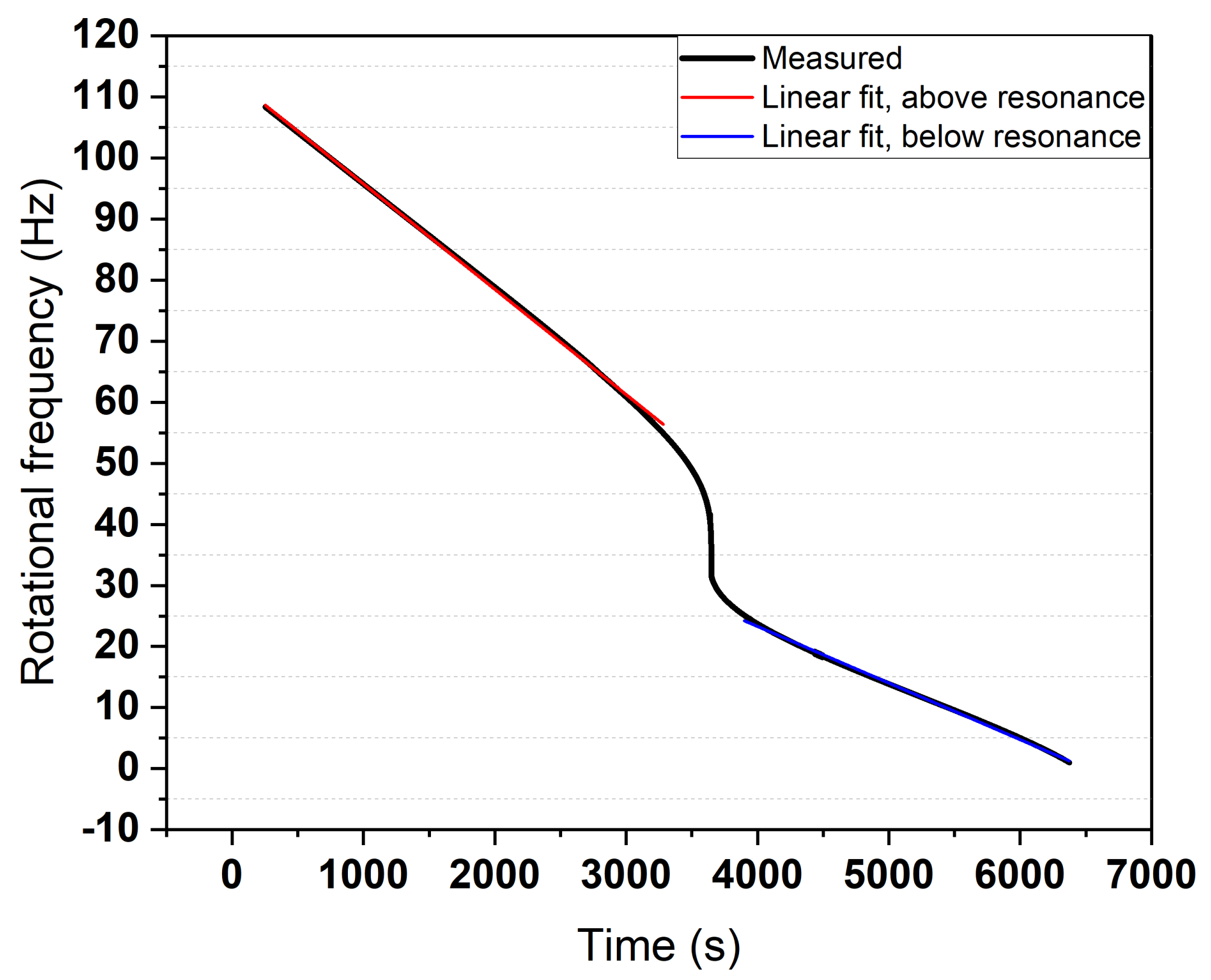
where k is geometric factor of order of unity, is magnetic field inhomogeneity, is the permeability of free space, and A/m is the critical current density of the YBCO puck, estimated from force-decay experiments [42]. From Equation (1), mW of power is dissipated due to magnetic field inhomogeneity. Figure 4 shows the deceleration of the PM (17 mm) during a spin-down test from 6600 rpm operated at 35 K. A resonance behaviour can be seen at 45 Hz. A deceleration rate of Hz/s (above resonance) and Hz/s (below resonance) was calculated by fitting a straight line to the data. The coefficient of friction is given by [10]:
where and are radius of gyration, and the mean radius at which the drag force is applied, respectively, is the deceleration rate and g is the acceleration of gravity. Because of the simple structure of the rotor, is assumed to be the rotor outer radius ( mm) [10].
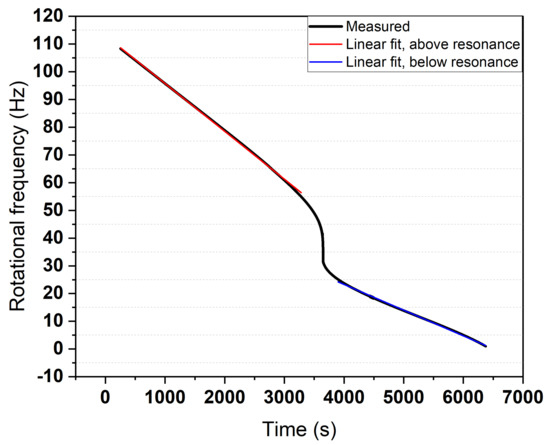
Figure 4.
PM spin-down after being released at 110Hz.
The energy stored E in the spinning magnet is given by [10]:
where is the moment of inertia, and is the angular velocity of the rotor. The energy loss per cycle is given by:
From Equation (2), the COF is larger above resonance than below resonance. This can be caused by the rotation of the PM around its center of mass, which can create a radial gradient in the magnetic field over the radius of YBCO puck [5]. Figure 5 shows the vertical oscillations of the PM during the spin-down test. The oscillation amplitude grows while the PM passes through resonance, reaching a maximum of mm.
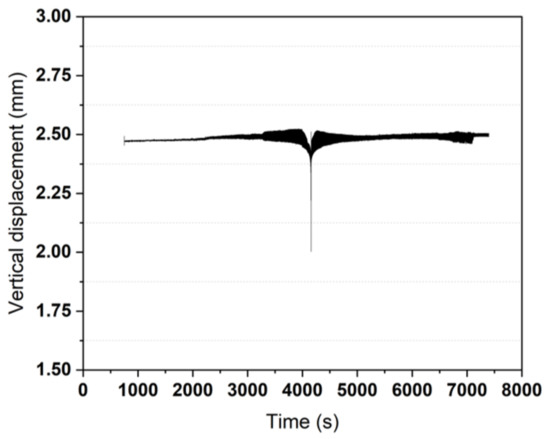
Figure 5.
Vertical oscillations of the PM.
From Equation (4), mW and mW of power is dissipated above and below resonance, respectively. The below-resonance power loss is consistent with the hysteresis loss as the total loss is dominated by hysteresis loss in that region. The larger power loss above resonance can be caused by additional radial components of magnetic field inhomogeneity created by the whirling motion of the PM in that region [5].
4. Conclusions
Superconducting magnetic bearings can be reliable solutions for overcoming the speed limit imposed by conventional bearings in rotating machinery. The coefficient of friction, which is measured through spin-down tests, was considered as a figure of merit to evaluate the performance of superconducting magnetic bearings. Engineering a reliable test rig to perform spin-down tests has always been a challenge. An experimental rig was designed and built, allowing PM self-centring and accommodating different PM sizes. Test runs proved its ability to accelerate, release, and recapture the levitating PM. Initial spin-down results show that the total rotational loss is dominated by hysteresis loss below resonance, and whirling motion above resonance can cause further energy dissipation. With this rig, we aimed to carry out spin-down experiments up to a target speed of 30,000 rpm, on magnets of various sizes and levels of inhomogeneity.
Author Contributions
Conceptualization: R.A.B.; supervision: R.A.B. and J.G.S.; coupling design: M.S.; software: L.W. and M.S.; validation: M.S. and L.W.; methodology and modeling: M.S. and J.G.S.; test setup building: L.W.; experiments and data curation: M.S.; writing—original draft preparation: M.S.; writing—review and editing: J.G.S. and R.A.B.; project administration: R.A.B.; funding acquisition: R.A.B. All authors have read and agreed to the published version of the manuscript.
Funding
This work was funded by the New Zealand Ministry of Business, Innovation and Employment (MBIE) under contract RTVU1707.
Institutional Review Board Statement
Not applicable.
Informed Consent Statement
Not applicable.
Data Availability Statement
The data presented in this study are available on request from the corresponding author.
Acknowledgments
The authors wish to acknowledge the invaluable technical advice and assistance provided by Grant Kellett, Fergus Robinson, and Mike Davies.
Conflicts of Interest
The authors declare no conflict of interest. The funders had no role in the design of the study; in the collection, analyses, or interpretation of data; in the writing of the manuscript, or in the decision to publish the results.
References
- Kalsi, S.; Hamilton, K.; Buckley, R.; Badcock, R. Superconducting AC Homopolar Machines for High-Speed Applications. Energies 2018, 12, 86. [Google Scholar] [CrossRef] [Green Version]
- Yonnet, J.P. Passive magnetic bearings with permanent magnets. IEEE Trans. Magn. 1978, 14, 803–805. [Google Scholar] [CrossRef] [Green Version]
- Uzhegov, N.; Smirnov, A.; Park, C.H.; Ahn, J.H.; Heikkinen, J.; Pyrhonen, J. Design Aspects of High-Speed Electrical Machines With Active Magnetic Bearings for Compressor Applications. IEEE Trans. Ind. Electron. 2017, 64, 8427–8436. [Google Scholar] [CrossRef]
- Maslen, E.H.; Schweitzer, G. (Eds.) Magnetic Bearings; Springer: Berlin/Heidelberg, Germany, 2009. [Google Scholar] [CrossRef]
- Hull, J.R. Superconducting bearings. Supercond. Sci. Technol. 2000, 13, R1–R15. [Google Scholar] [CrossRef] [Green Version]
- Hull, J.; Murakami, M. Applications of bulk high-temperature Superconductors. Proc. IEEE 2004, 92, 1705–1718. [Google Scholar] [CrossRef] [Green Version]
- Moon, F.C. Superconducting Levitation: Applications to Bearings and Magnetic Transportation; John Wiley & Sons: Hoboken, NJ, USA, 2008. [Google Scholar]
- Riise, A.B. Levitation Force and Magnetization in Bulk and Thin Film High TC Superconductors; Technical Report; Oslo Univ.: Oslo, Norway, 1998. [Google Scholar]
- Earnshaw, S. On the nature of the molecular forces which regulate the constitution of the luminiferous ether. Trans. Camb. Philos. Soc. 1848, 7, 97. [Google Scholar]
- Hull, J.R.; Mulcahp, T.M.; Uherka, K.L.; Erck, R.A.; Abboud, R.G. Flywheel energy storage using superconducting magnetic bearings. Appl. Supercond. 1994, 2, 449–455. [Google Scholar] [CrossRef] [Green Version]
- Terentiev, A.; Kuznetsov, A. Drift of levitated YBCO superconductor induced by both a variable magnetic field and a vibration. Phys. C Supercond. 1992, 195, 41–46. [Google Scholar] [CrossRef]
- Strasik, M.; Hull, J.; Mittleider, J.; Gonder, J.; Johnson, P.; McCrary, K.; McIver, C. An overview of Boeing flywheel energy storage systems with high-temperature superconducting bearings. Supercond. Sci. Technol. 2010, 23, 034021. [Google Scholar] [CrossRef]
- Weinberger, B.; Lynds, L.; Hull, J.; Balachandran, U. Low friction in high temperature superconductor bearings. Appl. Phys. Lett. 1991, 59, 1132–1134. [Google Scholar] [CrossRef]
- Hull, J.R.; Mulcahy, T.M.; Labataille, J.F. Velocity dependence of rotational loss in Evershed-type superconducting bearings. Appl. Phys. Lett. 1997, 70, 655–657. [Google Scholar] [CrossRef]
- Han, Y.; Hull, J.; Han, S.; Jeong, N.; Oh, J.; Sung, T.H. Losses of superconductor journal bearing. AIP Conf. Proc. 2004, 710, 1899–1905. [Google Scholar] [CrossRef]
- Hull, J.R.; Mulcahy, T.; Uherka, K.; Abboud, R. Low rotational drag in high-temperature superconducting bearings. IEEE Trans. Appl. Supercond. 1995, 5, 626–629. [Google Scholar] [CrossRef]
- Ye, M.; Yang, W.; Liu, Y.; Li, Y.; Yu, L. A Design Method of HTS Bulks Array for Decreasing Rotation Loss in a Superconducting Maglev Microthrust Stand. IEEE Trans. Appl. Supercond. 2018, 28, 1–5. [Google Scholar] [CrossRef]
- Lee, J.P.; Han, S.C.; Park, B.C. Experimental estimation on magnetic friction of superconductor flywheel energy storage system. J. Magn. 2011, 16, 124–128. [Google Scholar] [CrossRef] [Green Version]
- Cansiz, A.; Campbell, A.; Coombs, T. An Evershed type superconducting flywheel bearing. Phys. C Supercond. 2003, 390, 305–310. [Google Scholar] [CrossRef]
- Cansiz, A.; Hull, J.R. Stable load-carrying and rotational loss characteristics of diamagnetic bearings. IEEE Trans. Magn. 2004, 40, 1636–1641. [Google Scholar] [CrossRef]
- Jin, S.; Yincai, Z.; Xing, B.; Xiang, G.; Jihao, W.; Qing, L. Simulation and calculation on rotation loss of high temperature superconducting bearings. Phys. C Supercond. Its Appl. 2020, 568, 1353565. [Google Scholar] [CrossRef]
- Hikihara, T.; Adachi, H.; Moon, F.C.; Ueda, Y. Dynamical behavior of flywheel rotor suspended by hysteretic force of HTSC magnetic bearing. J. Sound Vib. 1999, 228, 871–887. [Google Scholar] [CrossRef]
- Day, A.C.; Hull, J.R.; Strasik, M.; Johnson, P.E.; McCrary, K.E.; Edwards, J.; Mittleider, J.A.; Schindler, J.R.; Hawkins, R.A.; Yoder, M.L. Temperature and frequency effects in a high-performance superconducting bearing. IEEE Trans. Appl. Supercond. 2003, 13, 2179–2184. [Google Scholar] [CrossRef]
- Werfel, F.; Flögel-Delor, U.; Rothfeld, R.; Wippich, D.; Riedel, T. Centrifuge advances using HTS magnetic bearings. Phys. C Supercond. 2001, 354, 13–17. [Google Scholar] [CrossRef]
- Xu, K.x.; Wu, D.j.; Jiao, Y.; Zheng, M. A fully superconducting bearing system for flywheel applications. Supercond. Sci. Technol. 2016, 29, 064001. [Google Scholar] [CrossRef]
- Hull, J.; Strasik, M.; Mittleider, J.; Gonder, J.; Johnson, P.; McCrary, K.; McIver, C. High rotational-rate rotor with high-temperature superconducting bearings. IEEE Trans. Appl. Supercond. 2009, 19, 2078–2082. [Google Scholar] [CrossRef]
- Strasik, M.; Hull, J.; Johnson, P.; Mittleider, J.; McCrary, K.; McIver, C.; Day, A. Performance of a conduction-cooled high-temperature superconducting bearing. Mater. Sci. Eng. B 2008, 151, 195–198. [Google Scholar] [CrossRef]
- Kaya, Y.; Cansiz, A.; Yildizer, I. Driving Mechanism of a Superconducting Magnetic Bearing System. J. Supercond. Nov. Magn. 2012, 26, 1233–1239. [Google Scholar] [CrossRef]
- Cansiz, A.; Yildizer, I.; Oral, E.A.; Kaya, Y. An Effective Noncontact Torque Mechanism and Design Considerations for an Evershed-Type Superconducting Magnetic Bearing System. IEEE Trans. Appl. Supercond. 2014, 24, 22–29. [Google Scholar] [CrossRef]
- Matsumura, T.; Hanany, S.; Hull, J.; Johnson, B.; Jones, T. Magnetic Field Inhomogeneity and Torque in High Temperature Superconducting Magnetic Bearings. IEEE Trans. Appiled Supercond. 2005, 15, 2316–2319. [Google Scholar] [CrossRef]
- Matsumura, T.; Sakurai, Y.; Kataza, H.; Utsunomiya, S.; Yamamoto, R. Magnetically coupled gear based drive mechanism for contactless continuous rotation using superconducting magnetic bearing below 10 K. Phys. C Supercond. Its Appl. 2016, 530, 138–141. [Google Scholar] [CrossRef]
- Mechatronic Drive Systems. Available online: https://www.maxongroup.com (accessed on 20 January 2021).
- Edwards. Available online: https://www.edwardsvacuum.com/en (accessed on 20 January 2021).
- Oxford Cryosystem. Available online: https://www.oxcryo.com/ (accessed on 20 January 2021).
- Keyence. Available online: https://www.keyence.com/ (accessed on 20 January 2021).
- Monarch Instrument. Available online: https://monarchinstrument.com/ (accessed on 20 January 2021).
- S950 Silicon Diode Temperature Sensor Product Folder. Available online: https://www.cryocon.com/S900ProdFolder.php (accessed on 20 January 2021).
- Model 26C High Output Power Temperature Controller Product Folder. Available online: https://www.cryocon.com/M26CProdFolder.php (accessed on 20 January 2021).
- Specialising in the Design and Manufacture of High Performance Hall Sensors. Available online: https://www.ahsltd.com/ (accessed on 20 January 2021).
- Triomotion. Available online: https://www.triomotion.uk/ (accessed on 20 January 2021).
- Clem, J.R. AC losses in high-T c materials. In Advances in Superconductivity X; Springer: Berlin/Heidelberg, Germany, 1998; pp. 23–28. [Google Scholar]
- Siamaki, M.; Storey, J.G.; Badcock, R.A. Towards a Non-Destructive Method of Mapping the E-J Relation Using Force Decay Measurements on Superconducting Bulks. IEEE Trans. Appl. Supercond. 2021, 31, 1–5. [Google Scholar] [CrossRef]


Publisher’s Note: MDPI stays neutral with regard to jurisdictional claims in published maps and institutional affiliations. |
© 2022 by the authors. Licensee MDPI, Basel, Switzerland. This article is an open access article distributed under the terms and conditions of the Creative Commons Attribution (CC BY) license (https://creativecommons.org/licenses/by/4.0/).