Article

Methanol Production in the Brayton Cycle

Institute of Power Engineering and Turbomachinery, Silesian University of Technology, Konarskiego 18, 44-100 Gliwice, Poland
*
Authors to whom correspondence should be addressed.
Energies 2022, 15(4), 1480; https://doi.org/10.3390/en15041480
Submission received: 24 January 2022 / Revised: 14 February 2022 / Accepted: 15 February 2022 / Published: 17 February 2022

Abstract

:
This article presents the concept of renewable methanol production in the gas turbine cycle. As part of the work, an analysis was performed, including the impact of changing the parameters in the methanol reactor on the obtained values of power, yield and efficiency of the reactor, and chemical conversion. The aim of this research was to investigate the possibility of integrating the system for the production of renewable methanol and additional production of electricity in the system. The efficiency of the chemical conversion process and the efficiency of the methanol reactor increases with increasing pressure and decreasing temperature. The highest efficiency values, respectively η = 0.4388 and η R = 0.3649, are obtained for parameters in the reactor equal to 160 °C and 14 MPa. The amount of heat exchanged in all exchangers reached the highest value for 14 MPa and 160 °C and amounted to Q ˙   = 2.28 kW. Additionally, it has been calculated that if an additional exchanger is used before the expander (heating the medium to 560 °C), the expander’s power will cover the compressor’s electricity demand.

1. Introduction

Methanol currently plays a very important role in the chemical industry and is a promising energy fuel, mainly produced from fossil fuels. Some of the alternatives under investigation use biogas, shale gas or captured CO2, and hydrogen. The CO2 hydrogenation pathway, which contributes to the switch to renewable fuels, gives rise to a set of alternative pathways differing in CO2 and hydrogen sources [1].
Carbon dioxide used in the methanol production process can be captured from fossil fuel power plants or directly from the air, where the latest is the only route fully compatible with the principles of the circular economy. In addition, electrolysis of water as a source of hydrogen can be powered by any form of renewable energy, such as solar or wind energy. There are also other interesting methods of obtaining hydrogen, including the use of ammonia borane as its source [2,3].
The overall concept of (green) methanol production is presented in Figure 1 [4]. It includes the supply of energy from renewable sources to the grid, where the excess energy from them is transferred to the hydrogen generator. The obtained hydrogen and carbon dioxide captured from the flue gases of a conventional power plant are supplied as substrates for the production of methanol.
Global methanol consumption reached 98.3 million tonnes in 2019 and is expected to exceed 120 million tonnes by 2025 and 500 million tonnes by 2050. China, as the world’s largest producer and methanol consumer that accounts for more than half of the total global demand, consumed about 55 Mt of methanol in 2018, wherein 25% of it was used in the fuel industry. Over the next ten years, China is projected to see the greatest increase in demand in the future, because applications, such as transport and heating fuels expand. However, mainly for economic reasons, methanol is still almost exclusively produced from fossil fuels. About 65% of methanol production is based on natural gas reforming (gray methanol), while the rest (35%) is largely based on coal gasification (brown methanol). Currently, only about 0.2% comes from renewable sources (green methanol) [4,5,6].
The production of “renewable” methanol is based on four basic sources: biomass, municipal waste, industrial waste, and carbon dioxide. The first three are based on gasification and catalytic conversion technology. The last variant, using carbon dioxide, water, and surplus electricity from RES, is the most ecological option for its production. Catalytic hydrogenation of carbon dioxide is currently the technology with the greatest development prospects and a relatively high probability of being introduced in the near future as a commercial technology on a large scale [7,8].
Liquid methanol is synthesized via the exothermic reaction between hydrogen and carbon dioxide (or carbon monoxide) according to the following reactions [9]:
CO ( g )   +   2 H 2 ( g )     CH 3 OH ( l ) Δ H = 128   kJ / mol   ( 298   K )
CO 2 ( g )   +   3 H 2 ( g )     CH 3 OH ( l )   +   H 2 O ( g ) Δ H = 87   kJ / mol   ( 298   K )
In parallel, there is also a reverse endothermic reaction of the conversion to water vapor.
CO 2 ( g )   +   H 2 ( g )     CO ( g )   +   H 2 O ( g ) Δ H = + 41   kJ / mol   ( 298   K )
7.277   kg   CO 2 ( g ) + 1   kg   H 2 ( g )     5.298   kg   CH 3 OH ( l ) + 2.979   H 2 O ( g )
The need to mitigate climate change and the elimination of carbon dioxide emissions from all types of energy consumption has increased global interest in renewable methanol. This type of production may increase the use of methanol as a chemical raw material and support industry and transport sectors in neutralizing carbon dioxide emissions, which is at a high level in these sectors of the economy. Moreover, renewable methanol can contribute to the improvement of the functioning of the energy system by storing energy in liquid form, which undoubtedly has advantages in the ease of transport compared to other forms of energy storage in gaseous forms. Currently, the cost of producing methanol from renewable sources is high and the production volume is low. With the right policies and falling renewable energy prices, green methanol could be cost-competitive until 2050 or even earlier. Methanol, for energy purposes, is mainly used in fuel cells, reciprocating engines, and gas turbines [10,11].
In the conventional methanol industry, typical reactor operating conditions are 50–100 bar and 200–300 °C. The authors’ research shows that an increase in temperature leads to an increase in methanol production to some extent, and then a decrease in it. The authors obtained the best performance at a temperature of 270 °C and a pressure of 50 bar, which is in line with those commonly used on an industrial scale in low-pressure methanol production processes [12,13]. In [14] it was found that the temperature of the maximum methanol yield moves up with the increase in pressure from about 235 °C to 250 °C for 40 to 100 bar, respectively. According to the researchers, methanol efficiency will increase with increasing pressure.
The influence of the working pressure on the yield of methanol at a fixed ratio of hydrogen to carbon dioxide equal to three and reaction temperatures ranging from 200 °C to 300 °C was investigated in [15]. In all tested cases, better menthol recovery was observed at higher working pressure and this effect was slight at low temperatures (200 °C) and dominant at higher temperatures. It has been found that the optimal process temperature (the one where the maximum yield has decreased with increasing operating pressure) for which the maximum yield is obtained is 240 °C at 50–60 bar, 230 °C at 70–90 bar, and 220 °C at 100 bar. The presented results may prove helpful in the selection of appropriate operational conditions for increasing the efficiency of the methanol synthesis process.
The gas turbine plays an increasingly important role in the petrochemical industry. In the industry, open-circuit gas power plants are widely used. Typically, a gas turbine works on the principle of internal combustion. Air passes through the compressor and then enters the combustion chamber. The products of combustion are expanded in a turbine, then drive an electric generator. The gas turbine is one of the most widely used devices to support the energy consumption of offshore platforms due to the multiple uses of fuel. However, the main negative effect of such engines is lower efficiency and large energy losses from the exhaust gas. The efficiency of the gas turbine is about 40% [16,17].
In order to improve the energy efficiency of the gas turbine and reduce the waste of resources, several methods are proposed to recover the thermal energy contained in the exhaust gas, such as heat exchangers installed in the exhaust path. The heat recovered from the flue gas can be used internally or externally. Conventional techniques for internal waste heat recovery include steam regeneration and injection, which are always integrated into gas turbine assemblies. A gas turbine with a steam injection into the combustion chamber is called a STIG turbine (Steam Injection Gas Turbine) [18]. In [19], the authors proposed the selection of a steam injection cooling scheme for a CHP plant and analyzed the operation of a gas turbine in a steam injection configuration. Steam injection by heat recovery steam generators improved the exergy efficiency of the system and reduced carbon dioxide emissions. In turn, other researchers [20] focused on the thermo-environmental and economic operation of the steam injection method with heat recovery, based on a power plant in northeastern Iran. The authors present a comprehensive model based on energy, exergy, environmental, and economic analyzes. The final model introduced the optimal conditions for the injection of steam into the combustion chamber. The optimum steam temperature of 318.5 °C was found at an ambient temperature of 38 °C and a relative humidity of 10%. The introduced heat recovery at the optimal steam temperature increased the power and net thermal efficiency by 56 MW and 4.6%, and also reduced the costs of energy production by 25.5%. Multivariate analyses of the operation of modern gas turbines operating in a wide range of pressures and with various methods of cooling are presented by authors in [21,22,23].
Gas turbines are widely used for energy generation due to their efficiency and low carbon dioxide emissions. Gas turbine plants are constantly evolving to meet the electricity demand of developing societies and economies. The gas turbine system consists of a compressor, combustion chamber, and expander. Each open and closed cycle gas turbine works in four processes, such as compression, combustion, expansion, and heat dissipation. Air is used as a refrigerant that is compressed in the compressor, combustion takes place in the combustion chamber, and the resulting exhaust gases are fed to the expander to produce energy. The gas turbine cycle is based on the Brayton cycle. The ideal Brayton cycle is characterized as a thermodynamic cycle that consists of isentropic and adiabatic gas compression followed by the addition of heat at constant pressure, and the extraction of energy by expanding the gas, as shown in Figure 2a–c [24,25].
The concept of combining a gas turbine system with methanol production was presented in [17]. The authors’ concept combines a gas turbine and a low-pressure installation for the production of methanol using the Lurgi method. Methanol is produced by catalytic hydrogenation of carbon monoxide and/or carbon dioxide in a methanol synthesis reactor. In the system behind the reactor there is a gas turbine in which high operating pressure generated electricity [17, 26].
In [27], the integration between a power-to-methanol energy storage system and a chemically recuperated gas turbine (CRGT) power plant was investigated. The selected configuration leads to an efficiency of the power-to-methanol process of around 60%. The obtained methanol flow rate enables the supply of a small (several kW) gas turbine equipped with a methanol reforming section in order to increase the efficiency of the installation. CRGT power plants can be an interesting low-carbon technology for the use of renewable methanol, enabling efficient storage of surplus renewable energy, and then producing electricity with low CO2 emissions.
In [28], a new method of fuel conversion was applied, consisting of combustion in a chemical loop in a gas turbine cycle powered with methanol with an intercooler. The methanol-fueled chemical loop gas turbine cycle represents a breakthrough in both the efficient use of alternative fuels and the mitigation of greenhouse gas emissions. The results obtained by the authors indicate that the gas turbine cycle with combustion in a chemical loop driven by methanol can provide a promising approach to both the efficient use of alternative fuel and the recovery of low-temperature waste heat.
The research of [29] has been proposed as an integrated system that includes an externally fired gas turbine (EFGT), a fuel cell (MCFC), an Organic Rankine Cycle (ORC), methane and/or methanol production, and a proton exchange membrane electrolyser (PEME). Three different production scenarios covering methane only, methanol only, and dual production, are investigated, considering the different operational loads of the electrolyser. If 10% of the energy produced is used by the electrolysis process to produce hydrogen used in the synthesis of methanol, the overall energy efficiency is 41%. In this case, the system uses 1012 tonnes/year of CO2 to produce 393 tons of methanol per year.
The authors present a unique analysis of alternative fuel production systems in conjunction with a gas turbine cycle. The originality of the presented analyses is emphasized by the fact that they are performed in a wide range of pressure and temperature. The analyses available in the literature on the subject focus mainly on the analysis of the chemical side of the processes and operation of the reactor [9,30]. The complexity of the analyses carried out in this article covers the entire process of producing “green” methanol, from the use of renewable energy to the production of hydrogen, using CO2 and also electricity production in the gas turbine cycle. This research expands and shows other modern possibilities of using a gas turbine for the production of methanol [27,28].
One should also not overlook the fact that the production of methanol uses carbon dioxide, which is largely responsible for the aggravation of climate change and global warming. Its use, for example, captured from the exhaust of a conventional power plant, may contribute to global climate change mitigation. According to the circular economy in which the consumption of raw materials and the amount of waste, as well as emission and loss of energy, are minimized by creating a closed loop of processes, in our case, CO2 is used as raw material for production of methanol, which minimizes the amount of production waste [31,32].

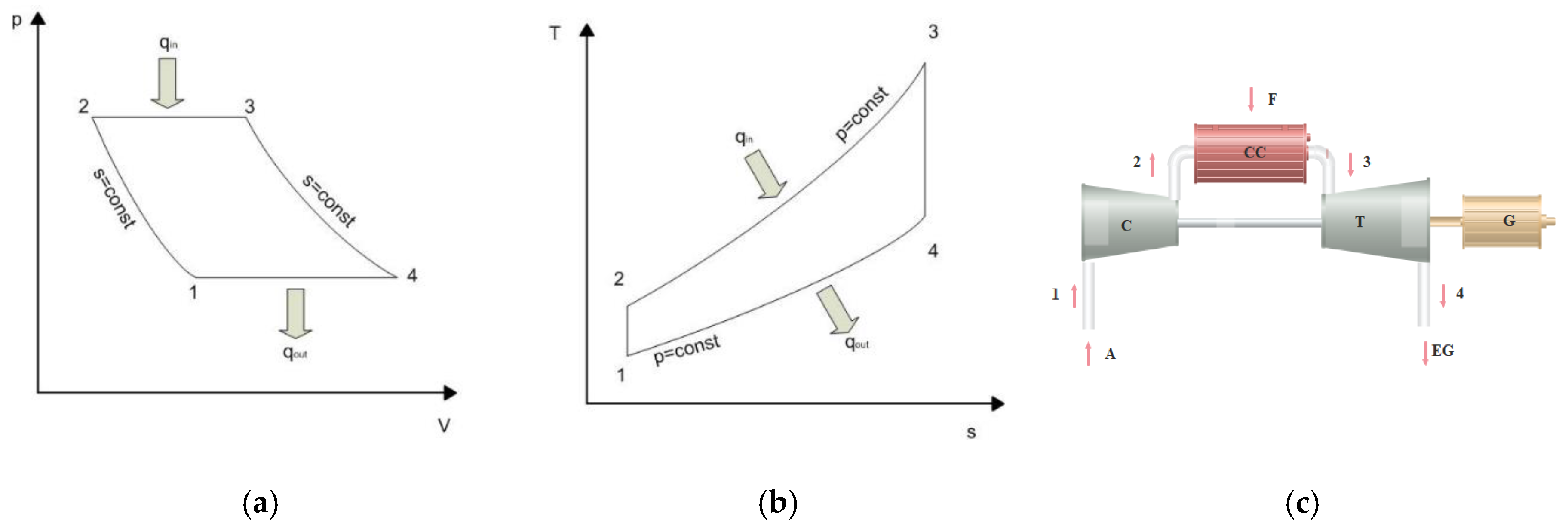
2. A System for the Methanol Production in the Gas Turbine Cycle

The proposed installation for the methanol production is shown in Figure 3. In the initial phase, carbon dioxide is compressed to an appropriate pressure, then mixed with hydrogen, and the entire mixture is compressed again to the pressure required in the system. The mixture, prepared in this way, is directed to the heat exchanger HX1, where the heat is collected in order to adjust the temperature to the synthesis in the reactor, R. The methanol reactor operates in the temperature range from 160 °C to 220 °C and in the high pressure range from 8 MPa to 14 MPa. After passing through the reactor, the mixture is directed to the expander T, where electricity is produced.
The mixture is then directed to the heat exchanger HX2, where the heat is collected and the moisture condenses, simultaneously. Subsequently, the mixture is directed to separator S. In separator S, liquid methanol is collected while the remaining stream is directed to the membrane MR. After passing through the membrane, the separated hydrogen and carbon dioxide are recycled back into recompression and go through the process. Assumed parameters in the installation at characteristic points of circulation are presented in Table 1.

3. Methodology of Calculations

The calculation methodology was taken from the authors’ previous research on methanol production presented in [26,27].
The balance of components present in the reaction of methanol formation is carried out in accordance with the relationship (4). The efficiency of the methanol reactor is defined as the ratio of the amount of methanol obtained in the process to the theoretical amount of methanol determined from Equation (4), in accordance with:
η R = u C H 3 O H u C H 3 O H , s t e c
uCH3OH—pure methanol yield, kgCH3OH/kgH2
uCH3OH,stec—pure methanol yield calculated from Equation (4), kgCH3OH/kgH2
The efficiency of the chemical conversion process is the ratio of the chemical energy of the methanol formed to the amount of chemical energy supplied to the hydrogen process, according to the relationship:
η = H H V C H 3 O H · m ˙ C H 3 O H H H V H 2 · m ˙ H 2
HHVCH3OH—22,341.21 kJ/kg
HHVH2—142,327 kJ/kg
The amount of heat exchanged in the process is the sum of heat exchanged in all three exchangers:
Q ˙ = Q ˙ H X 1 + Q ˙ H X 2 + Q ˙ H X 3
Q ˙   —amount of heat exchanged in all exchangers, kW
Q ˙ H X   —amount of heat exchanged in the exchanger, kW
The amount of heat exchanged in individual exchangers is the product of the mass flow of a given factor and its enthalpy difference:
Q ˙ H X 1 = m ˙ · ( i i n i o u t )
m ˙   —the flow of the medium that exchanges heat in the exchanger, kg/s
i i n —enthalpy of the medium at the inlet to the exchanger, kJ/kg
i o u t   —enthalpy of the medium at the outlet of the exchanger, kJ/kg

4. The Results of the Analyses

The results of the obtained values at characteristic points of the installation are presented in Table 2.
As part of the analysis of the results, graphs were drawn showing the effect of pressure and temperature changes (in point 8 in Figure 3) at the reactor inlet on:
  • total amount of heat from heat exchangers HX1, HX2, HX3 ( Q ˙ H X 1 ,   Q ˙ H X 2 , Q ˙ H X 3 );
  • gas turbine power (NT);
  • total power of compressors C (ΣNc);
  • yield ( u C H 3 O H ) ;
  • efficiency of the chemical conversion ( η );
  • reactor efficiency ( η R ).
Figure 4 presents the results of calculating the power of the NT gas turbine depending on the parameters in the reactor (pressure and temperature). The value of the power increases with the increase of these parameters. The highest power is obtained for 220 °C and 14 MPa, and amounts to NT = 1.96 kW, and the lowest for 160 °C and 8 MPa (NT = 1.62 kW). By changing the temperature t8 by 10 °C, the power increase by 0.024 kW is noticeable. By changing the pressure p8 by 1 MPa, the power increase is 0.032 kW. Increasing the pressure p8 by 1 MPa allows for a greater increase in power than increasing the temperature t8 by 10 °C.
Calculation results of the power of all three compressors in the system depending on the pressure p8 and the temperature t8 in the methanol reactor are presented in Figure 5. The value of the total power ΣNc increases with increasing the assumed parameters. For the conditions prevailing in the reactor of 220 °C and 14 MPa, the highest power of compressors is obtained, equal to ΣNc = 2.97 kW, and the lowest value for 160 °C and 8 MPa (ΣNc = 2.35 kW). A 10 °C change in t8 temperature causes a noticeable power increase of about 0.026 kW. The change in pressure p8 by 1 MPa causes the power increase of 0.078 kW. Increasing the pressure p8 by 1 MPa allows for a greater increase in power than increasing the temperature t8 by 10 °C. As the reaction (2) is exothermic, and the assumed temperature in the reactor t8 amounts to a maximum of 220 °C, it is not possible to obtain a higher turbine power, NT, than the total power of the compressors, ΣNc. It was checked that adding an additional heat source downstream of the reactor and heating the medium to 560 °C would increase the power of the NT turbine and exceed the total power of the compressors, ΣNc.
Figure 6 shows the results of analysis of all three heat exchangers in relation to changes in pressure p8 and temperature t8 in the methanol reactor. With the decrease in temperature t8 and the increase in pressure p8, the value of heat exchanged ( Q ˙ ) in the system increases. The amount of heat obtained for 160 °C and 14 MPa in the system reaches the highest value and amounts to Q ˙ = 2.28 kW. A change in temperature t8 by 10 °C causes a noticeable decrease in the amount of heat exchanged by 0.065 kW, and a change in pressure p8 by 1 MPa causes an increase in the amount of heat equal to 0.083 kW. Reducing the temperature, t8, by 10 °C allows for a smaller increase in heat exchanged than increasing the pressure, p8, by 1 MPa.
Figure 7 shows the results of the analysis of changes in the parameters to the chemical conversion efficiency η. The efficiency of the installation increases with the decrease in temperature, t8, and the increase in pressure, p8. The highest efficiency of the installation is achieved for 160 °C and 14 MPa (η = 0.3649), and the lowest for 220 °C and 8 MPa (η = 0.2037). The efficiency drop of 0.017 is due to a 10 °C change in temperature, t8. Increasing the pressure, p8, by 1 MPa causes an increase in the chemical conversion efficiency, η, equal to 0.01. A change in pressure, p8, by 1 MPa has a smaller effect on the efficiency, η, than a change in temperature, t8, by 10 °C.
The results of the ηR reactor efficiency analysis, depending on the pressure, p8, and the temperature, t8, in the reactor are shown in Figure 8. The reactor efficiency, ηR, in the analyzed installation increases with the increase of pressure, p8, and the decrease of the temperature, t8. The highest efficiency of the installation is achieved for 160 °C and 14 MPa (ηR = 0.4388), and the lowest for 220 °C and 8 MPa (ηR = 0.2449). An increase in temperature, t8, by 10 °C causes a degradation of efficiency by 0.021, while an increase in pressure, p8, by 1 MPa causes a jump in efficiency by 0.012. A 10 °C change in temperature, t8, has a greater effect on efficiency than a 1 MPa change in pressure, p8.
The amount of obtained methanol, u C H 3 O H , from the analyzed installation in relation to the change of parameters in the methanol reactor is shown in Figure 9. The value of the yield from the analyzed installation increases with increasing pressure, p8, and decreasing temperature, t8. The highest yield of 2.32 kg/h was achieved for 160 °C and 14 MPa. The smallest amount of methanol obtained from the system was 1.30 kg/h (at 220 °C and 8 MPa in point 8 in Figure 3). An increase in temperature, t8, by 10 °C causes a decrease in the amount of obtained product by 0.011 kg/h. Increasing the pressure, p8, by 1 MPa results in the amount of product obtained by 0.06 kg/h. A 10 °C change in temperature, t8, has a greater effect on the yield than a 1 MPa change in pressure, p8. Compared to the classic methanol production plant, the yield obtained in the analysis is lower by approximately 2 kgCH3OH/kgH2, which is due to the lack of an internal purification loop of the product.

5. Summary

The article presents the concept of methanol production in the form of the gas turbine cycle. The production process uses hydrogen from the electrolysis process and carbon dioxide captured from the exhaust gases of a conventional power plant. As part of the research, the analysis of pressure and temperature changes at the inlet of the methanol synthesis reactor was performed. Replacement in the gas turbine cycle of the combustion chamber with a reactor (in which the exothermic reaction takes place) results in a number of benefits. The produced methanol not only contributes to reducing the amount of CO2 in the atmosphere, but also to increasing the consumption of renewable energy. Additionally, it is possible to use methanol in a gas turbine as a fuel, as it allows for the production of electricity at the time of greater demand. Methanol is therefore an excellent energy carrier. The methanol produced in the installation (pipeline 17 in Figure 3) is in a liquid form, which makes it much easier and more profitable to transport.
The issues related to the development of effective and economically justified systems for the conversion of carbon dioxide into useful materials seem to be very promising in an era of continuously increasing fuel prices and the need to reduce CO2 emissions. The produced methanol may constitute a competitive marine or automotive fuel or chemical feedstock for its potential consumers. Renewable methanol enables a rapidly growing part of the global economy to become carbon neutral using existing processes and infrastructures, enabling cooperation between different sectors to reduce overall CO2 emissions and increase the importance of the circular economy. “Green” methanol is able to technically, economically, and practically reduce the greenhouse gas emissions of significant sections of the global economy [33].
As part of the analysis of the resulting charts, in order to open a wider discussion, the authors posed several research questions relating to the current work. This can trigger more broad interest in the future.
How did the change of parameters affect the value of the compressor and turbine power?
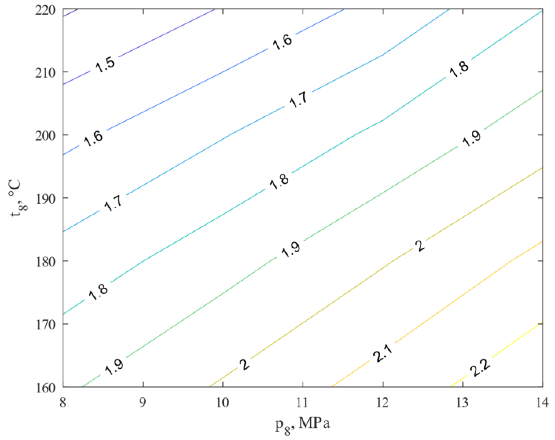
  • The power values of the compressor, ΣNc, and the NT turbine increase with the increase of temperature, t8, and pressure, p8, prevailing in the reactor, reaching the highest value of 14 MPa and 220 °C and are, respectively, ΣNc = 2.97 kW and NT = 1.96 kW.
For which operating parameters of the reactor were the highest value of heat exchanged achieved?
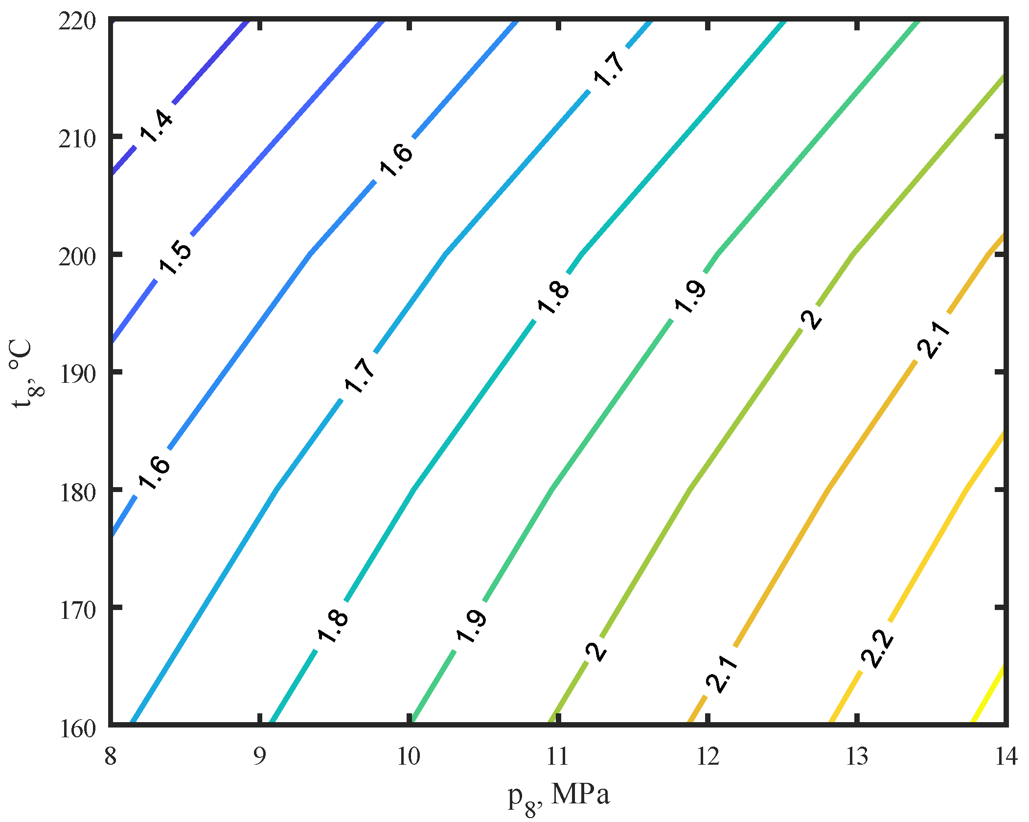
  • The amount of heat exchanged in all exchangers reached the highest value for 14 MPa and 160 °C, and equal 2.28 kW.
How do changes in pressure and temperature at reactor inlet effect methanol production efficiency and methanol reactor efficiency?
  • The efficiency of the methanol production process, η, and the efficiency of the methanol reactor increase with increasing pressure, p8, and decreasing temperature, t8. This represents the expected development towards higher reactor pressures.
Are there any options for retrofitting the system to meet the compressor’s energy demands?
  • Inserting an additional heat exchanger preceding the expander, which heats the medium to 560 °C, will increase the expander’s power so much that it will cover the compressor’s electricity demand.

Author Contributions

Conceptualization: J.K. and M.B.; formal analysis: M.B.; funding acquisition: M.B. and K.S.; investigation: J.K., M.B. and A.W.; methodology: J.K. and M.B.; resources: J.K. and M.B.; writing—original draft: K.S. and A.W. All authors have read and agreed to the published version of the manuscript.

Funding

Scientific work supported by the National Science Center as part of the research project: “Research on various structures of systems for the energetic use of methanol and its production based on H2 from the electrolysis process and CO2 from CCS installation” (project no 2018/29/B/ST8/02244). The presented work was financed by the Silesian University of Technology with means from statutory research funds.

Institutional Review Board Statement

Not applicable.

Informed Consent Statement

Not applicable.

Conflicts of Interest

The authors declare no conflict of interest.

Nomenclature

Q ˙ amount of heat, kW;
η R reactor efficiency, -;
HHVCH3OH22,341.21 kJ/kg;
HHVH2142,327 kJ/kg;
NTgas turbine power, kW;
ppressure, MPa;
ttemperature, °C;
uCH3OHpure methanol yield, kgCH3OH/kgH2;
uCH3OH,stecpure methanol yield kgCH3OH/kgH2;
ΣNctotal power of compressors, kW;
i enthalpy of the medium, kJ/kg;
η efficiency of the chemical conversion, -;
m ˙ the flow of the medium, kg/s.

Subscripts

.separator of subscripts;
1 ÷ 17numbers in characteristic points of installations;
CH3OHmethanol;
H2hydrogen;
CO2carbon dioxide;
COcarbon monoxide;
H2Owater.

Abbreviations

Aair;
Ccompressor;
CCcombustion chamber;
Ffuel;
Tgas turbine;
Ggenerator;
EGexhaust gas;
HXheat exchanger;
Rmethanol synthesis reactor;
Sseparator;
MRseparation membrane;
Ggenerator;
Mmotor;
CO2 carbon dioxide;
H2hydrogen;
H2Owater;
CH3OHmethanol.

References

  1. Vazquez, D.; Guillén-Gosálbez, G. Process design within planetary boundaries: Application to CO2 based methanol production. Chem. Eng. Sci. 2021, 246, 116891. [Google Scholar] [CrossRef]
  2. Eghbali, P.; Nişancı, B.; Metin, Ö. Graphene hydrogel supported palladium nanoparticles as an efficient and reusable heterogeneous catalysts in the transfer hydrogenation of nitroarenes using ammonia borane as a hydrogen source. Pure Appl. Chem. 2018, 90, 327–335. [Google Scholar] [CrossRef]
  3. Eghbali, P.; Gurbuzm, M.; Erturk, A.; Metin, Ö. In situ synthesis of dendrimer-encapsulated palladium(0) nanoparticles as catalysts for hydrogen production from the methanolysis of ammonia borane. Int. J. Hydrogen Energy 2020, 45, 26274–26285. [Google Scholar] [CrossRef]
  4. Coskun Avci, A.; Toklu, E. A new analysis of two phase flow on hydrogen production from water electrolysis. Int. J. Hydrogen Energy 2022, 47, 6986–6995. [Google Scholar] [CrossRef]
  5. Ravikumar, D.; Keoleian, G.; Miller, S. The environmental opportunity cost of using renewable energy for carbon capture and utilization for methanol production. Appl. Energy 2020, 279, 115770. [Google Scholar] [CrossRef]
  6. Berggren, M. Global methanol—State of the industry. In Proceedings of the 22nd IMPCA Asian Methanol Conference, Singapore, 5–7 November 2019. [Google Scholar]
  7. Osman, M.; Zaabout, A.; Cloete, S.; Amini, S. Pressurized chemical looping methane reforming to syngas for efficient methanol production: Experimental and process simulation study. Adv. Appl. Energy 2021, 4, 100069. [Google Scholar] [CrossRef]
  8. Schorn, F.; Breuer, J.; Samsun, R.; Schnorbus, T.; Heuser, B.; Peters, R.; Stolten, D. Methanol as a renewable energy carrier: An assessment of production and transportation costs for selected global locations. Adv. Appl. Energy 2021, 3, 100050. [Google Scholar] [CrossRef]
  9. Kotowicz, J.; Węcel, D.; Brzęczek, M. Analysis of the work of a “renewable” methanol production installation based ON H2 from electrolysis and CO2 from power plants. Energy 2021, 221, 119538. [Google Scholar] [CrossRef]
  10. Chen, C.; Yang, A. Power-to-methanol: The role of process flexibility in the integration of variable renewable energy into chemical production. Energy Convers. Manag. 2021, 228, 113673. [Google Scholar] [CrossRef]
  11. Bos, M.; Kersten, S.; Brilman, D. Wind power to methanol: Renewable methanol production using electricity, electrolysis of water and CO2 air capture. Appl. Energy 2020, 264, 114672. [Google Scholar] [CrossRef]
  12. Cui, X.; Kær, S.; Nielsen, M. Energy analysis and surrogate modeling for the green methanol production under dynamic operating conditions. Fuel 2022, 307, 121924. [Google Scholar] [CrossRef]
  13. Iwakiri, I.; Miguel, C.; Madeira, L. Modeling and simulation of a steam-selective membrane reactor for power-to-methanol. Comput. Chem. Eng. 2022, 156, 107555. [Google Scholar] [CrossRef]
  14. Kiss, A.; Pragt, J.; Vos, H.; Bargeman, G.; de Groot, M. Novel efficient process for methanol synthesis by CO2 hydrogenation. Chem. Eng. J. 2016, 284, 260–269. [Google Scholar] [CrossRef] [Green Version]
  15. Lee, B.; Lee, H.; Lim, D.; Brigljević, B.; Cho, W.; Cho, H.-S.; Kim, C.-H.; Lim, H. Renewable methanol synthesis from renewable H2 and captured CO2: How can power-to-liquid technology be economically feasible? Appl. Energy 2020, 279, 115827. [Google Scholar] [CrossRef]
  16. Gou, X.; Zhang, H.; Li, G.; Cao, Y.; Zhang, Q. Dynamic simulation of a gas turbine for heat recovery at varying load and environment conditions. Appl. Therm. Eng. 2021, 195, 117014. [Google Scholar] [CrossRef]
  17. Kralj, A.; Glavic, P. Optimization of a gas turbine in the methanol process, using the NLP model. Appl. Therm. Eng. 2007, 27, 1799–1805. [Google Scholar] [CrossRef]
  18. Carapellucci, R.; Milazzo, A. Repowering combined cycle power plants by a modified STIG configuration. Energy Convers. Manag. 2007, 48, 1590–1600. [Google Scholar] [CrossRef]
  19. Vadlamudi, T.; Kommineni, R.; Katuru, B. Exploration of turbine blade cooling strategies for performance boosting and CO2 emissions reduction of combined cycle with steam injection based gas turbine. Int. J. Ambient Energy 2020. [Google Scholar] [CrossRef]
  20. Rad, E.; Kazemiani-Najafabadi, P. Thermo-environmental and economic analyses of an integrated heat recovery steam-injected gas turbine. Energy 2017, 141, 1940–1954. [Google Scholar] [CrossRef]
  21. Kotowicz, J.; Brzęczek, M. Analysis of increasing efficiency of modern combined cycle power plant: A case study. Energy 2018, 153, 90–99. [Google Scholar] [CrossRef]
  22. Kotowicz, J.; Brzęczek, M. Comprehensive multivariable analysis of the possibility of an increase in the electrical efficiency of a modern combined cycle power plant with and without a CO2 capture and compression installations study. Energy 2019, 175, 1100–1120. [Google Scholar] [CrossRef]
  23. Kotowicz, J.; Brzęczek, M.; Job, M. The thermodynamic and economic characteristics of the modern combined cycle power plant with gas turbine steam cooling. Energy 2018, 164, 359–376. [Google Scholar] [CrossRef]
  24. Salilew, W.; Karim, Z.; Baheta, A. Review on gas turbine condition based diagnosis method. Mater. Today Proc. 2021. [Google Scholar] [CrossRef]
  25. Tahan, M.; Muhammad, M.; Karim, Z. A multi-nets ANN model for real-time performance-based automatic fault diagnosis of industrial gas turbine engines. J. Braz. Soc. Mech. Sci. Eng. 2017, 39, 2865–2876. [Google Scholar] [CrossRef]
  26. Greeff, I.; Visser, J.A.; Ptasiński, K.; Janssen, F. Utilisation of reactor heat in methanol synthesis to reduce compressor duty—Application of power cycle principles and simulation tools. Appl. Therm. Eng. 2002, 22, 1549–1558. [Google Scholar] [CrossRef]
  27. Tola, V.; Lonis, F. Low CO2 emissions chemically recuperated gas turbines fed by renewable methanol. Appl. Energy 2021, 298, 117146. [Google Scholar] [CrossRef]
  28. Jin, H.; Zhang, X.; Hong, H.; Han, W. An innovative gas turbine cycle with methanol-fueled chemical-looping combustion. J. Eng. Gas Turbine Power 2009, 131, 061701. [Google Scholar] [CrossRef]
  29. Eisavi, B.; Ranjbar, F.; Nami, H.; Chitsaz, A. Low-carbon biomass-fueled integrated system for power, methane and methanol production. Energy Convers. Manag. 2022, 253, 115163. [Google Scholar] [CrossRef]
  30. Kotowicz, J.; Brzęczek, M. Methods to increase the efficiency of production and purification installations of renewable methanol. Renew. Energy 2021, 177, 568–583. [Google Scholar] [CrossRef]
  31. Aydin, M.; Dincer, I. An assessment study on various clean hydrogen production methods. Energy 2022, 245, 123090. [Google Scholar] [CrossRef]
  32. Dar, A.; Hameed, J.; Huo, C.; Sarfraz, M.; Albasher, G.; Wang, C.; Nawaz, A. Recent optimization and panelizing measures for green energy projects; insights into CO2 emission influencing to circular economy. Fuel 2022, 314, 12094. [Google Scholar] [CrossRef]
  33. Altayib, K.; Dincer, I. Development of an integrated hydropower system with hydrogen and methanol production. Energy 2022, 240, 122780. [Google Scholar] [CrossRef]
Figure 1. General scheme of the renewable methanol production concept.
Energies 15 01480 g001
Figure 2. (a). Brayton’s cycle in the p-V plot. (b). Brayton cycle in a T-s plot. (c). General scheme of a gas turbine (A: air; C: compressor; CC: combustion chamber; F: fuel; T: expander; G: generator; EG: exhaust gas).
Energies 15 01480 g002
Figure 3. Installation of methanol production in the gas turbine cycle (C: compressor; HX-heat exchanger; T: gas turbine; R: methanol synthesis reactor; S: separator; MR: separation membrane; G: generator; M: motor; Q: heat; CO2: carbon dioxide; H2: hydrogen; H2O: water; CH3OH: methanol).
Energies 15 01480 g003
Figure 4. Influence of changes in pressure p8 and temperature t8 at the reactor inlet (Figure 3) on the power of the gas turbine NT in kW.
Energies 15 01480 g004
Figure 5. Influence of changes in pressure p8 and temperature t8 at the reactor inlet (Figure 3) on the total power of compressors ΣNc in kW.
Energies 15 01480 g005
Figure 6. Influence of changes in pressure, p8, and temperature, t8, at the reactor inlet (Figure 3) on the total amount of heat from the exchangers HX1, HX2, and HX3 ( Q ˙ H X 1 , Q ˙ H X 2 , Q ˙ H X 3 ), in kW.
Energies 15 01480 g006
Figure 7. Influence of changes in pressure p8 and temperature t8 at the reactor inlet (Figure 3) on the chemical conversion efficiency η.
Energies 15 01480 g007
Figure 8. Influence of changes in pressure, p8, and temperature, t8, at the reactor inlet (Figure 3) on the reactor efficiency, η R .
Energies 15 01480 g008
Figure 9. Influence of changes in pressure, p8, and temperature, t8, at the reactor inlet (Figure 3) on the yield of methanol, u C H 3 O H , in kgCH3OH/kgH2.
Energies 15 01480 g009
Table 1. Assumptions for the installation of methanol production in the gas turbine cycle.
Parameter, UnitSymbolValue
Hydrogen pressure at the inlet system inlet, MPap12.5
Carbon dioxide pressure at the system inlet, MPap20.15
Hydrogen temperature at the inlet to the installation, °Ct125
Temperature of carbon dioxide at the inlet to the installation, °Ct225
Pressure at the outlet of the gas turbine, -p10150
Isentropic efficiency of a gas turbine, -ηiT0.9
Mechanical efficiency of a gas turbine, -ηmT0.99
Isentropic efficiency of compressors, -ηiC0.88
Mechanical efficiency of compressors, -ηmC0.995
Electric efficiency of the engine, -ηmel0.95
Mechanical efficiency of the engine, -ηmm0.998
Generator nominal efficiency, -ηng0.9856
Table 2. Examples of the analysis results obtained for the pressure of 14 MPa and the temperature of 160 °C at the inlet to the reactor in point 8.
Lpm
[kg/h]
p
[MPa]
t
[°C]
i
[kJ/kg]
X
[-]
CH3OHH2CO2COH2O
10.452.525356.9101000
23.340.152520.8100100
30.552.525356.9101000
41.002.525356.9101000
57.282.5272.9257.0100100
68.282.5107.5269.0100.120.8800
78.2814342.6890.5100.120.8800
88.2814160404.6100.120.8800
98.2814290.6649.410.280.070.4800.01
108.280.1543.7−158.50.90.280.070.4800.01
118.280.1515−349.00.80.280.070.4800.01
121.280.1515.063.1000000
137.000.151531.910.340.080.5600.01
147.000.151512.4100100
150.550.1515213.9101000
160.552.5126.61821.4101000
172.320.151522.6100000
Publisher’s Note: MDPI stays neutral with regard to jurisdictional claims in published maps and institutional affiliations.

