4.3. Simulation Results
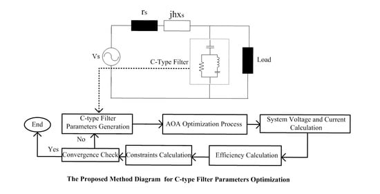
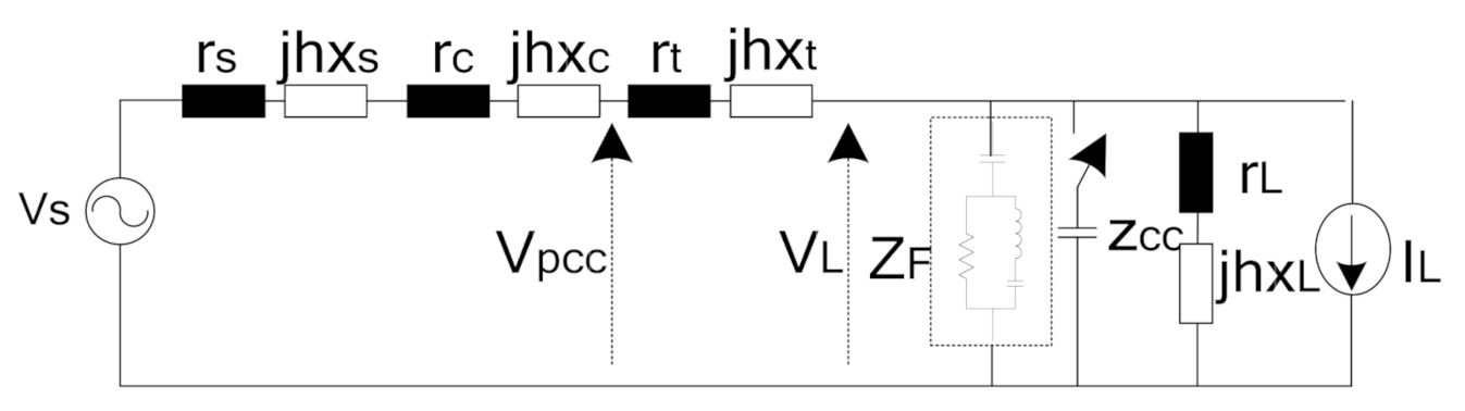
The three-phase short-circuit power of system in
Figure 3 is 800 MVA, and the rated line voltage is 6.35 kV. The impedances of the system and load are shown in
Table 1. These values are reported at the fundamental frequency. The equivalent Thevenin resistance is 0.0038 Ω and this value is reported for the first order harmonic component. Its reactance amplitude at this frequency is 0.0506 Ω. A power cable with 640 A ampacity, length of 0.1 km and 6.35 kV rated voltage was considered. It should be noted that its reactance and also resistance values at the fundamental frequency were considered as 0.0098 Ω and 0.0104 Ω. The rated power of the consumer transformer is 7 MVA and its voltage ratio is 6.3 kV/0.4 kV. The transformer resistances are set as 0.026, 0.006, and 0.012 ohms, respectively, and the inductive reactance value is given 0.221 ohms. The load bus powers including active and reactive powers were assumed to be 4.9 MW and 4.965 MVAr. The 4 and 4.05 ohms are the load resistance and reactance, respectively, at the fundamental order harmonic. A capacitor bank compensates the reactive power for the loads, and
referred to the transformer primary side is 100 Ω.
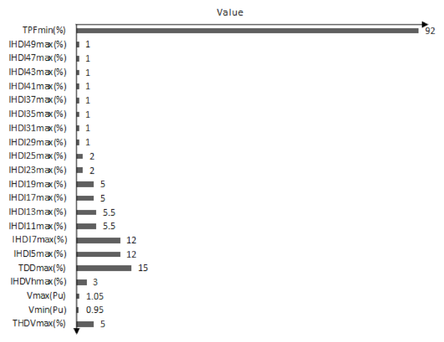
The harmonic characteristic of the system and connected linear load and individual capacitor were calculated based on the proposed Equations (13)–(21) in
Section 3. In addition, the nonlinear load was simulated using harmonic current injections at harmonic orders which are shown in
Table 2 [
46]. The harmonic voltage distortion, which is shown in
Table 2, is referred to the utility side’s one. The simulations were performed using the MATLAB software package.
The uncompensated system results are tabulated in
Table 3. It can be seen from
Table 3 that
is close to
, but both
and
are significantly greater than their allowable values. It can be concluded from
Table 3 that the
value in scenario 1 is close to the allowable value,
, (as shown in
Figure 6); in scenario 2, due to the lack of individual capacitor, its value has exceeded the allowable limit. However, both
and
are significantly higher than their allowable values. In addition, represented results show that the considered power factor expressions, for both scenarios, are very small due to the harmonic pollution and lack of reactive power. The results of scenario 2 also show that the capacitor uninstallation leads to more reduction in total harmonic distortion and power factor, and therefore poorer PQ. It shows that the connected capacitor to the load bus does not affect the
DPF value improvement. The motors
value also has a high amplitude. In addition, components power losses values are large and it shows that system harmonic overloading aggregated.
As shown in
Table 3, the optimum finding of CTF parameters can improve the PQ of the studied system. Therefore, optimization process based on the
OF presented in (49) was performed. In addition, to find the optimization problem, the AOA and the HHO algorithms were implemented using the MATLAB software package. The search agents’ number and the maximum iterations number were set to 50 and 400, correspondingly. The presented results are reported as an average value over 30 independent runs.
The optimal parameters for the simulated filter and the best fitness amplitudes by the HHO and the AOA algorithms are given in
Table 4. Moreover, the worst, mean, and standard deviation of the obtained fitness parameters and the computation times are explained in the same table.
It is shown in
Table 4 that the two considered algorithms represent the best fit parameters. For scenario 1, the represented results by the AOA are superior to the results of the HHO optimizer in terms of best-fit (=5) and mean (=6.7) values. The minimum values of the standard deviation index of the AOA (0.13) and the HHO (0.136) indicate their high robustness. In addition, the AOA has a lower time for computation to reach the best fitness value than the HHO algorithm over the identical iterations number, and also the runs. According to the results, it is clear that the capacitors amount used in the CTF in scenario 2 is more than in scenario 1, because in scenario 1, a portion of the reactive power of the load is supplied by the individual capacitor. Therefore, lower reactive power will be delivered from the filter in this plan.
The comparison of the results show that the optimal solution is achieved with better standard deviation and running time. The results also show that the proposed method might have advantages when compared with the proposed method in [
29].
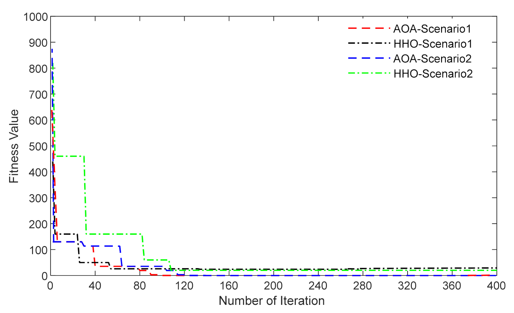
In addition, the convergence rate for both algorithms and both studied scenarios were illustrated in
Figure 7 for the sake of a better comparison between the two implemented algorithms. This is a typical diagram for 30 run numbers that, for example, a sample convergence diagram has been shown in
Figure 7. The compensated system results and also the optimum calculated parameters for the studied filter for the proposed OFs are tabulated in
Table 5.
For the uncompensated system, a negligible harmonic current can make very high voltage distortion, as displayed in
Table 3, due to the nonlinear relationship between them [
28]. Comparison of the results presented in
Table 3 and
Table 5 shows that the general performance of the proposed method is satisfactory.
Table 5 shows that the proposed technique leads to the supply current reduction, lower transmission losses, higher transmission efficiency, and higher loads power factor than the non-compensated system parameters represented in
Table 3. In addition, it is clear that the total harmonic voltage distortion is intensely diminished, satisfying the required OF and complying with the IEEE standard 519-1992.
According to the results, CTF implementation increases the
PF and the
DPF, and decreases the voltage
THD, thus avoiding the production of harmonic currents in the network. As presented in
Table 5, for the two scenarios of the compensated system, the total harmonic distortion indices (
THDV and THDI) measured at the
PCC and load bus are below the IEEE standard limit (5%). The
TDD values are lower than the IEEE standard constraint (15%) in all achieved results.
It can be seen that the
and
values provided by scenario 1 have fewer amplitudes than obtained values in scenario 2; therefore, lower reactive power will be passed, even though the filter’s resistor (R) and its inductive property (LF) provided by scenario 1 have lower amplitudes than the obtained results by the scenario 2. In addition,
Table 5 shows the filter parameters that have been calculated based on the scenario 1.
According to these calculated parameters, a lower
has been obtained than in the other scenario. Besides, as represented in
Table 5, the suggested filter design by scenario 1 results in higher
and
compared to the other scenario. In addition,
is superior to values that have been achieved by scenario 1.
As represented in
Table 5, the filter parameters calculated by scenario 1 resulted in lower harmonic distortion values than in scenario 2. This issue clarifies a lower harmonic system component risk.
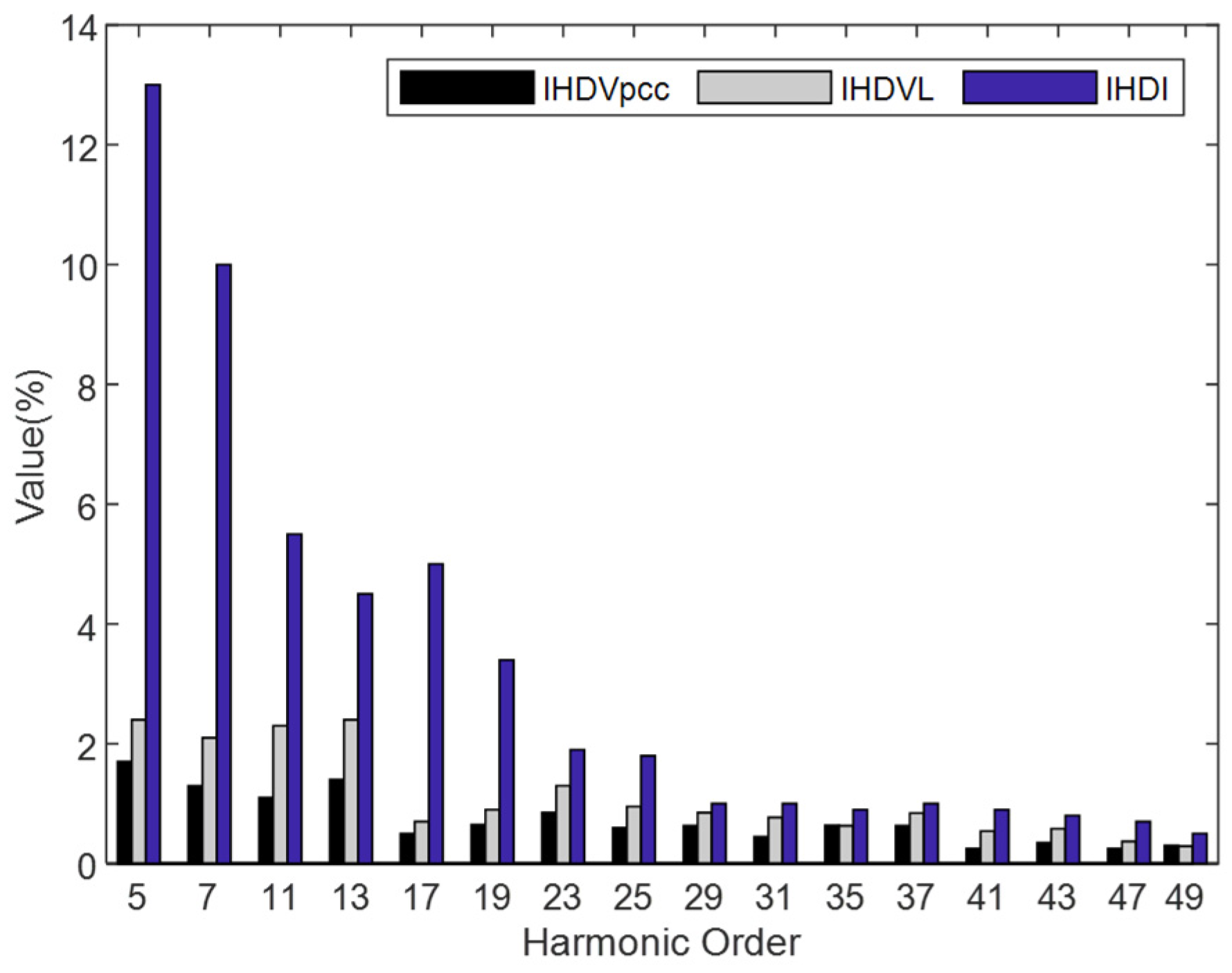
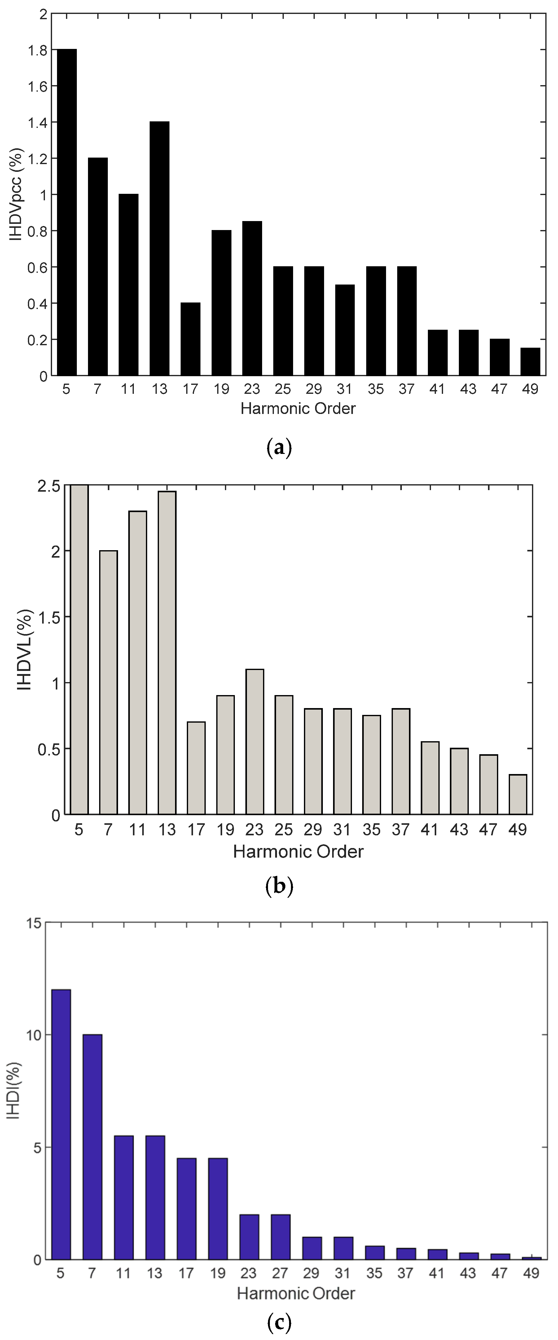
Moreover, the different harmonic amplitudes of current and also voltage, shown in
Figure 8 and
Figure 9 for
,
, and
, are lower than the IEEE 519 limits for every order of harmonics, which have been presented in
Figure 6. As shown in
Figure 8 and
Figure 9, for both two scenarios, the IHDV and IHDI are below the IEEE standard limit. Moreover, these parameters for scenario 2 have higher values than scenario 1. This condition is due to the fact that some harmonic distortions were compensated by the individual capacitor in scenario 1.
To show the POF performance, the CTF parameters which have been optimized in this paper were compared with the results obtained from the OF in [
29]. Both simulations were done for scenario 1 and based on the AOA method. The obtained results are represented in
Table 6.
It can be noticed that
and
are improved from 91.85% to 92.63% and 90.84 to 91.56, respectively.
is increased from 99.03% to 99.83%. Furthermore, all two methods provide almost all the
and
values below the standard threshold. For both OFs, the amount of harmonic voltage distortion, as well as the
, is less than the standard thresholds. In addition, the calculated
by the POF has a smaller amplitude than the proposed method in [
29]. According to the results, the obtained values of C
F1 and C
F2 in the POF have lower values. This indicates that less reactive power must be injected into the system by the CTF.
and
for the POF have higher amplitudes rather than the function proposed in [
29]. Calculated
by the POF has been improved compared to the previous works due to the harmonic dependency of these parameters. Generally, the achieved results indicate an effective harmonics reduction in the studied system compared to the OF in [
29].
The comparison of the results shows that, based on the POF, the optimal solution is achieved with a better power factor, higher transmission efficiency and lower losses in Thevenin’s resistor. Additionally, the results proved that the proposed method has better performance compared to the proposed method in [
29], where all the resultant values of
THD are lower than for other investigated cases. Besides,
Figure 10 shows the
,
, and
, respectively which were calculated based on the proposed OF in [
29] by the AOA algorithm. As shown in
Figure 10, the voltage and current distortion values of the individual harmonic are well below the IEEE 519 limits for the individual harmonic distortion limits, but by comparing
Figure 8 and
Figure 10, it is obvious that the POF leads to the lower individual harmonics amplitudes compared to the proposed OF in [
29].
In addition, to validate the proposed method, the obtained simulation results were compared with the results and findings of [
29]. All results were reported based on the Harris Hawks algorithm, as tabulated in
Table 7. As shown in
Table 7, the achieved results based on the proposed objective function in [
29] are similar to the obtained results in this reference. In addition, the proposed objective function has better performance compared to the objective function in [
29]. It can be noticed that
and
are improved from 86.38% to 89.95% and 90.77 to 91.23, respectively. Furthermore, all two objective functions provide almost all the
and
values below the IEEE standard threshold.
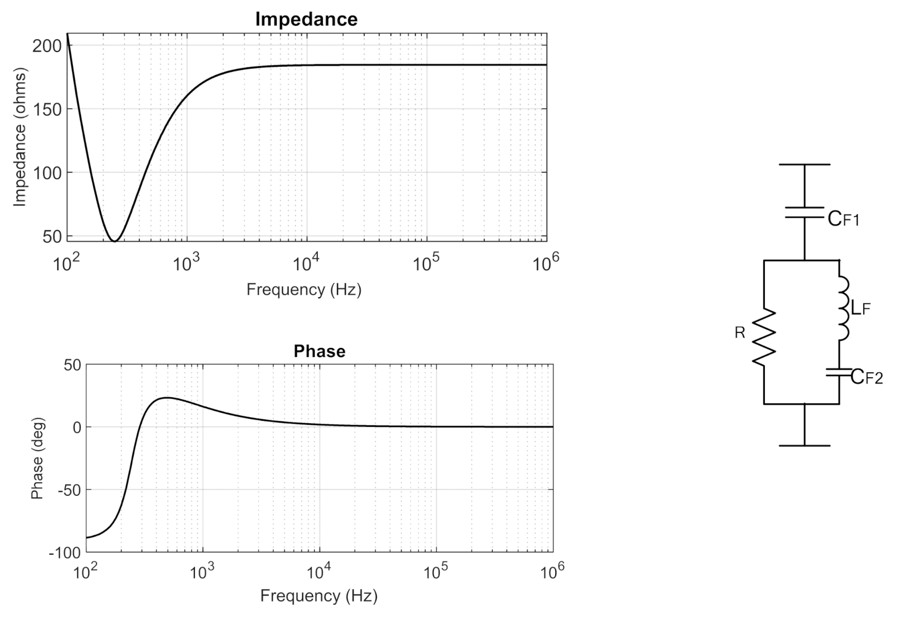
The simplest type of harmonic passive filter is the 1st order filter which is comprised of a capacitor in series with a resistor. The capacitor is used to provide capacitive reactance for
correction, and the resistor provides the damping characteristic. The second order filter is comprised of an inductor in parallel with a resistor R, and the resulted circuit is in series with the capacitor. High power loss is the disadvantage of these two mentioned filters, and basically, to get better harmonic filtering performance, the tuned filters with further reduction of the fundamental power losses were implemented, which are named the third order passive filter and the C-type passive third order filter, and operate as a single-tuned filter at low frequencies below the tuning one; therefore, the fundamental loss has been reduced. At high frequencies, above the tuning frequency, the filter will operate as the 1st order harmonic passive filters. The C-type filter has no fundamental loss and is below the tuning frequency, therefore it acts as the 2nd order filters. At high frequencies, above the tuning frequency, the filter will operate in a similar manner to the first order harmonic passive filters [
37].
According to the above explanation, the performance of these two types of third order harmonic filters will be compared for scenario 1.
Table 8 shows the impact of the designed filters using the AOA on the system performance. Besides, the uncompensated system results are included for comparison. By using the third order filter and C-type filters, respectively, it can be noticed that
is improved from 70.2339% to 91.85% and 92.63%, and
is increased from 45.1853% to 92.63% and 91.56%.
is increased from 94.75.7 to 99.83 and 99.03%, respectively. Furthermore, all three filters provide almost the same
and
values below the standard thresholds. Lastly, with the employment of third order and C-Type filters,
is decreased from 0.9596 to 0.7732 and 0.7642, respectively, and
is increased from 0.9728 to 0.9949 and 0.9957, respectively. This means that for the effective utilization of the lines, the C-type filter accomplishes improved performance compared to another filter. Besides, the comparative analysis validates that the C-type filter provides a higher power factor, system efficiency and transmission loss improvement than the third order filter.


