Article

Low-Grade Flow Energy Harvesting by Low-Mass-Ratio Oscillating Bent Plate

1
School of Power and Mechanical Engineering, Wuhan University, Wuhan 430072, China
2
Key Laboratory of Hydraulic Machinery Transients (MOE), Wuhan University, Wuhan 430072, China
*
Author to whom correspondence should be addressed.
Energies 2022, 15(5), 1606; https://doi.org/10.3390/en15051606
Submission received: 1 December 2021 / Revised: 19 January 2022 / Accepted: 2 February 2022 / Published: 22 February 2022
(This article belongs to the Topic Sustainable Energy Technology)

Abstract

:
Low-grade renewable energy possesses large reserves and a wide distribution in the environment, but it is far from fully exploited due to the high cost–income ratio when using traditional convertors. A fluid-induced-vibration-based flow energy convertor with a low-cost bent plate as an oscillator is proposed to achieve better energy converting performance for low-grade flow energy conversion. The energy extraction performance and dynamic response of the bent plate are assessed numerically. The results demonstrate that the prescribed single-DOF (degree of freedom) bent plate can reach the maximum efficiency of 29.6% and power coefficient of 2.36 at the relative plunging amplitude of 3.5, while the double-DOF bent plate achieves a maximum efficiency of 37.3% and power coefficient of 1.42 at a smaller amplitude of 1.4. It is discovered that the adoption of pitching motion can help to control the variation pattern of the effective AOA (angle of attack), while the camber of the bent plate also regulates the effective AOA from the geometrical respect. The FIV-based single-DOF convertor can achieve an energy converting efficiency of 29.3% and approach the ideal sinusoidal motion trajectory closely, indicating that the optimal active motion mode can be realized by the passive motion mode with the appropriate choice of the dynamic parameters.

1. Introduction

Renewable energy (RE) has the strongest prospects for both slowing down climate change and replacing fossil fuels [1], so the development and utilization of RE has been the focus of many studies over the past decades. Since many technologies have been developed to convert high-grade RE, including high water-head damps for high-grade water energy and large diameter axial flow wind turbines for high-grade wind energy, the conversion of low-grade RE has attracted increasing attention recently. As one kind of low-grade RE, flow-induced vibration energy is widely distributed in various environments. To achieve vibration-to-electric energy conversion, many vibration-based energy convertors have been proposed [2]. These convertors can be used to power small electronic devices including health monitoring sensors, medical implants, data transmitters, wireless sensors [3], and cameras [4]. Among varied vibration-based energy convertors, the FIV-based (fluid-induced-vibration-based) energy convertors may achieve a higher level of power conversion and even supply power to the grid.
To understand the energy conversion mechanism of FIV-based energy convertors, the effects of reduced velocity (U* = U/fND, determined by the oncoming flow velocity U, and oscillator natural frequency fN), mass ratio (m* = m/md, indicating the relative mass of the oscillator to the mass of fluid with same volume), damping (δ), and Reynolds number on the response of FIV-based oscillators (mainly cylinders with diameter of D) have been extensively studied. Some fundamental findings and conclusions have been established and widely accepted. The effect of the mass ratio and damping ratio on the peak amplitude of vibration (A) can be well characterized by the combined mass-damping parameter (δr = /ρD2), the product of mass and the damping ratio [5]. The peak amplitude increases with a decreasing mass-damping parameter in the Griffin plot [6]. When the mass ratio is reduced and less than a critical value, such as 0.54, resonant FIV can exist over a wider or even infinite regime of reduced velocity [7,8,9]. This means that the low mass ratio oscillator has a wider range of synchronization and thus better adaption to different flow velocities. Therefore, one key point in designing a FIV-based energy convertor is to reduce the mass ratio.
The range of resonance of the FIV-based oscillator and the related amplitude ratio increases with the increasing Reynolds number. An amplitude ratio (A* = A/D) of 1.9 can be reached at high Res [10]. The vibration amplitude increased with the reduced velocity Ur and demonstrates a galloping-like oscillation for the circular cylinder with a 2DOF system [11]. The fundamental studies on FIV indicate that a lower mass ratio and higher Reynolds number can promote FIV in terms of the peak vibration amplitude and bandwidth of the resonance region and thus may lead to better energy extraction performance. However, the FIV-based energy convertors are more likely to be applied in the relatively low Re cases, such as currents and tides [12], so another key point to achieve high-performance energy conversion is to realize a high amplitude resonance at low Res.
Bernitsas and Raghavan put forward the idea of using VIV (vortex-induced vibration) to generate energy from ocean/river currents and achieved a power coefficient of 0.22 [13]. Ding et al. [14] applied roughness strips on the cylinder surface to enhance flow-induced vibrations and thus improve the performance of the VIVACE (Vortex-Induced Vibration Aquatic Clean Energy) convertor to a power coefficient of 0.28. Zhang et al. [15] introduced a fixed cylinder downstream of the vibrating cylinder and proved that the energy extraction performance can be enhanced under optimized spacing distance. Hover et al. [16] conducted forced vibration experiments of the cylinder under a Re of 3800 with different combinations of oscillating amplitude (A*) and frequency (f*) and measured fluid force (CY) and phase shift between the cylinder velocity and the acceleration (Φ). The maps of CYsinΦ in the parameter space of (A*, f*) indicate that energy transfer from the fluid to the cylinder may happen for 5 < f* < 9 (positive CYsinΦ), and the VIV amplitude (A*) cannot exceed 0.8 (negative CYsinΦ). Based on Hover’s experiment, Barrero-Gil et al. [17] built a mathematical model of a VIV-based energy convertor and analyzed the influence of the mass ratio and damping on the energy extraction performance. The results revealed that a larger flow velocity range of significant efficiency can be achieved at a lower mass ratio.
The shape of the cross-section is another important factor affecting the aerodynamic characteristics and energy extraction performance of the FIV-based oscillator [18,19]. Zhang found the Cir-Tria prism has better energy extraction performance (power coefficient of 0.265) over the cylinder (0.146). The numerical results of Ding [18] show the better performance of the Q-trapezoid (0.457) over the PTC-cylinder (circular cylinder with passive turbulence control) (0.379). This single-DOF convertor is simple in structure and thus has the potential to harvest low-grade flow energy with low cost. However, according to the nonlinear distributed-parameter mode for the VIV-based energy convertors, the vortex-induced force or the lift force is the key factor to determine the energy extraction performance [20], and high plunging displacements should be obtained to design efficient VIV-based energy convertors [4]; in addition, a bluff oscillator such as the cylinder is not likely to achieve a high lift coefficient and large plunging amplitude, so the energy conversion performance of single-DOF FIV-based convertors is always limited.
Flapping or oscillating foils provide FIV-based convertors with a possible way to increase the peak lift coefficient and energy extraction performance. The flapping foil has two degrees of freedom, including plunging and pitching motions. The large angle of attack brought by the pitching motion leads to a high lift coefficient of up to 2 or more. A maximum efficiency of 43% was achieved at a high Reynolds number with prescribed motion in the 2D numerical simulation [21]. Based on the optimal prescribed motion, Jean-Christophe [22] further developed a fully passive flow energy convertor and reached two-dimensional efficiencies as high as 34%. With an additional generator to convert pitching power, a fully passive FIV-based convertor can attain an efficiency of 37.9% and a power coefficient of 1.1 [23]. An energy extraction efficiency of 31% and a power coefficient of 0.86 were reached in the water channel test [24]. The improved energy extraction performance of oscillating foils provides the possibility of high-level and large-scale FIV-based flow energy conversion. However, since two or three DOFs are involved in flapping foil energy conversion, a much more complicated structure is required to realize muti-DOF motions and thus achieve high energy conversion performance. The resulting high cost of the flapping-foil-based convertor will impede it from harvesting low-grade flow energy.
Compared with the single-DOF (degree of freedom) FIV-based energy convertors, the double-DOF convertors are more efficient. However, the single-DOF convertors are relatively simple from a mechanical point of view and thus are much more economical when converting low-grade flow energy. This work provides a new design of a FIV-based energy convertor that combines the advantages of the single-DOF and double-DOF FIV-based energy convertors. Furthermore, one of the key problems to be solved for FIV-based flow energy extraction is to reduce the mass ratio of the oscillator, so the cross-section shape, which can determine the mass ratio, is one main consideration in the present studies. This work proposes a new type of cross-section shape, namely a C-shaped bent-plate, which can provide a low mass ratio and is easily machined from a low-cost flat plate. The objective of this work is to investigate the possibility of using an oscillating bent plate to extract flow energy with 2D CFD simulation. A more accurate assessment of the flow patterns is possible using 3D numerical simulations [25], which have a significantly higher computational cost considering long-time transient simulations and multi-parameter optimization. This is beyond the scope of the present work. The high aspect ratio of the cross-section can increase the peak-lift coefficient and reduce the mass ratio of the oscillator. Particularly, we aim to determine the energy levels that can be generated from one and two-degree-of-freedom oscillating bent plates. With well-tuned motion and structural parameters, our single-DOF fully passive FIV-based energy convertor achieves an efficiency of 29.3% and power coefficient of 2.36, which is much higher than those with bluff bodies (such as cylinders). Owing to its highly simplified structure, potential low mass ratio, and relatively high energy conversion performance, this advanced FIV-based energy convertor offers an avenue for the large-scale utilization of low-grade flow energy.

2. Method

2.1. Problem Description

We have previously developed a flow energy convertor based on an elliptical foil [26] as shown in Figure 1. The convertor achieved a maximum efficiency of 20%. To improve the energy extraction performance of this VIV-based convertor, the elliptical foil is bent against the incoming flow to boost the shedding vortex and thus increase the lift. The C-shaped foil profile is generated from the projection of the elliptical section [27]. With an optimal foil shape, the convertor can reach a maximum power coefficient of 0.8 and an energy extraction efficiency of 28.5%. Using double generators to convert the flow energy, the power coefficient and efficiency are further increased to 37.9% [23]. However, the double-DOF motions of the C-shaped foil require a more complicated structure, and the shaped surface increases the manufacturing cost of the foil. In this work, we retain the camber of the foil but abandon the curved foil profile; thus, a three-section bent plate is proposed as shown. The foil is bent from a low-cost flat plate and has a lower mass ratio potentially. The chord length is defined as c. The camber height is denoted by w, and the relative camber height w/c is set to 0.135 according to our previous study [27]. The foil has three segments of an equal length of about 0.35c.

2.2. Numerics

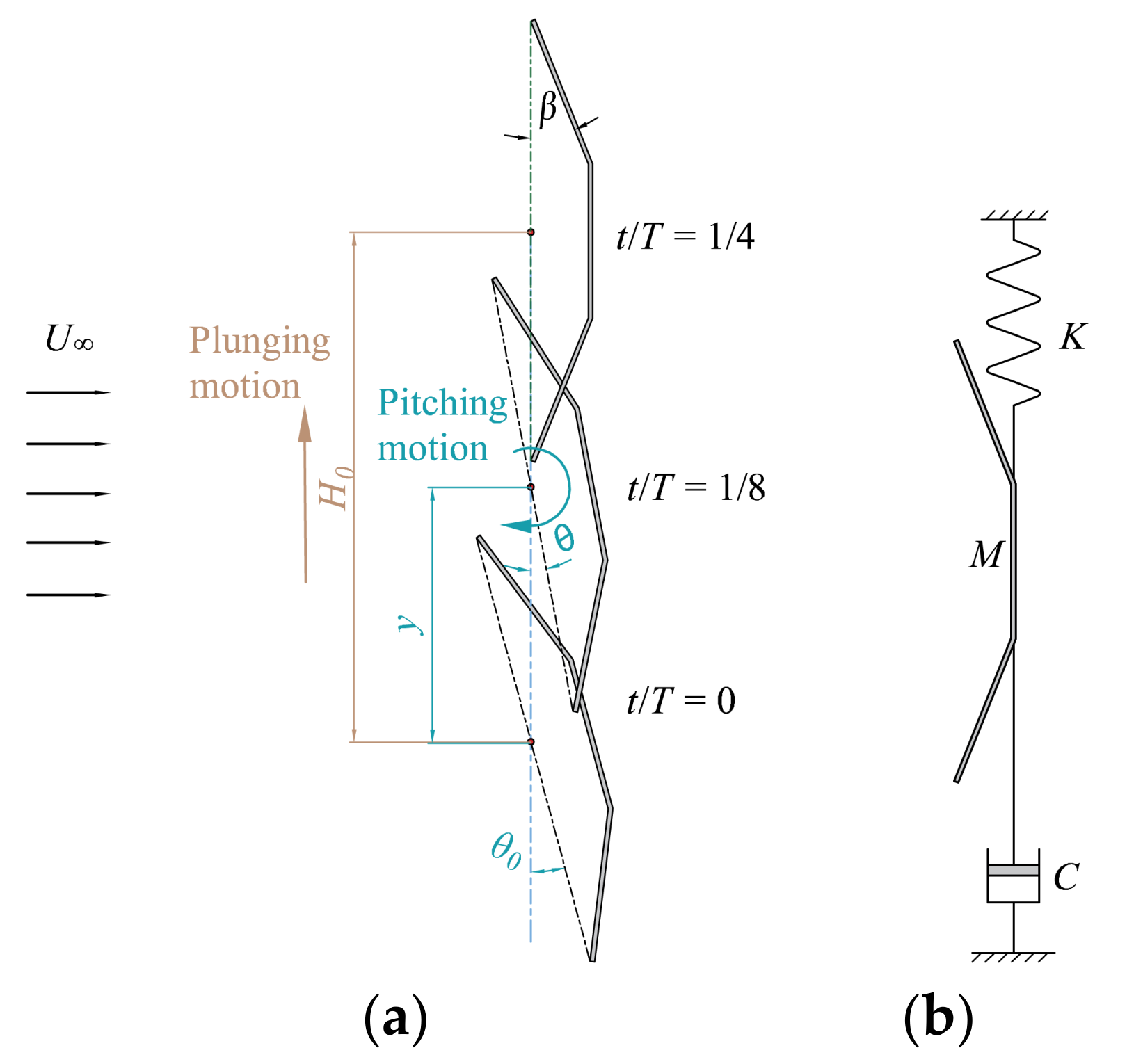
The bent plate can undergo prescribed single-DOF plunging and double-DOF combined plunging (or heaving) and pitching motions as shown in Figure 2a. The bent plate can also undergo flow-induced (passive) single-DOF plunging motion as shown in Figure 2b, and the motion trajectory is indirectly controlled by a spring and a damper. In the cases of prescribed motion, the plunging and pitching motions are described by Equations (1) and (2), respectively:
y ( t ) = H 0 sin ( 2 π f t )
θ ( t ) = θ 0 sin ( 2 π f t + φ )
where H0 and θ0 are the plunging and pitching amplitudes (see Figure 2a), f is the oscillating frequency, t is the time, and φ is the phase difference between pitching and plunging motions (in radians). In contrast to most oscillating foils with an average AOA (angle of attack) of 0, the oscillating bent plate is pitching around an AOA of 90°, so the pitching angle of the bent plate is defined as the angle between the chord line and crosswise direction, and the pitching or pivoting axis is located at the midpoint of the chord line. As the phase shift φ is set to 90°, in the upstroke (i − 1/4 ≤ t/T < i + 1/4), the foil maintains a positive AOA as shown in Figure 2a and the upward lift will drive the foil to plunge across the stream. At the end of upstroke (t/T = i + 1/4), the foil reverses and starts the downstroke (i + 1/4 ≤ i + t/T < i + 3/4). The reciprocating plunging motion can be used to drive a linear generator directly or a rotary generator through a rack or worm.
For a convertor with prescribed motion, the fluid transfers fluid energy to the bent plate by lift force, and the resulting power is calculated by
P fluid = F y V y
In the case of passive motion, the oscillating bent-plate convertor is treated as a mass–spring–damper system, and the plunging motion is described by a second-order oscillator equation:
M y ¨ ( t ) + C y ˙ ( t ) + K y ( t ) = F y ( t )
As shown in Figure 2b, the spring and the damper are set in the direction of the bent plate’s plunging motion, where the damper acts as a generator. Driven by the periodic lift force, the bent plate moves up and down, thus driving the generator to output electric energy. The stiffness of the spring is set as K, the damping of the damper is set as C, and the mass of the plate is set as M.
In this work, the mass ratio is fixed at 1, and the effects of mass-damping parameters and reduced velocity on energy harvesting performance of bent plate are examined. The actual efficiency and power coefficient of the bent plate can be calculated accordingly. The power output of the convertor can be evaluated by
P generator = C V y 2
For a balanced convertor, the cycle-averaged power input from the fluid and output to generator are equal to the following.
1 T 0 T F y V y d t = 1 T 0 T C V y 2 d t
Thus, the transient and average power coefficient can be calculated from
C P = P fluid 1 2 ρ U 3 c   o r     C P = P generator 1 2 ρ U 3 c
C P mean = 1 T 0 T C P d t
The definition of energy conversion efficiency η is as follows:
η = P mean 1 2 ρ U 3 d = C P mean c d
where d is the swept vertical distance.
As the foil is plunging, the relative velocity between the stream and the foil is changed, so the pitching angle alone cannot reflect the real AOA. In this case, the effective AOA is used and defined as follows:
αe = 90° − arctan (Vy/U0) − θβ
where arctan (Vy/U0) is the plunging motion-induced AOA, θ is the pitching motion-induced AOA, and β is the bending angle of the bent plate (see Figure 2a).

2.3. Computational Conditions

To simulate the large amplitude combined plunging and pitching motion of the oscillating bent plate, the fluid domain is subdivided into two subdomains to apply the sliding mesh technique as shown in Figure 3. The inner domain (Inner Zone) undergoes rigid body motion, while the outer domain (Outer Zone) smoothly remeshes as the domain deforms. The Inner Zone is a circular domain with a diameter of 16 chords that guarantees the continuity of the Inner Zone’s flow field. The Outer Zone is a rectangle domain (60 chords × 90 chords) with a circular hollow. The inlet, outlet, and symmetry boundaries are set to more than 30 chords away from the foil so that the boundary effect on the flow around the oscillating foil is negligible [28]. The Inner Zone grid and the Outer Zone grid are connected and exchange data by a sliding interface. Both the Inner Zone and Outer Zone are meshed with a block-structured O-grid to obtain the best grid quality. The velocity-inlet, pressure-outlet, and symmetry boundary conditions are applied at the inlet, outlet, and symmetries. The two-way fluid–structure interaction (FSI) problem is handled by the FLUENT UDF (user-defined function). The solid solver for the FSI problem solves the passive single-DOF motion of the rigid foil according to Equation (3) and is written into the UDF with C language code. A staggered, explicit coupling scheme between the solid solver and CFD (Computational Fluid Dynamic) solver has been chosen. The details of the coupling scheme between the foil motion solver and the CFD solver can be found in our previous study [25].

2.4. Verification and Validation

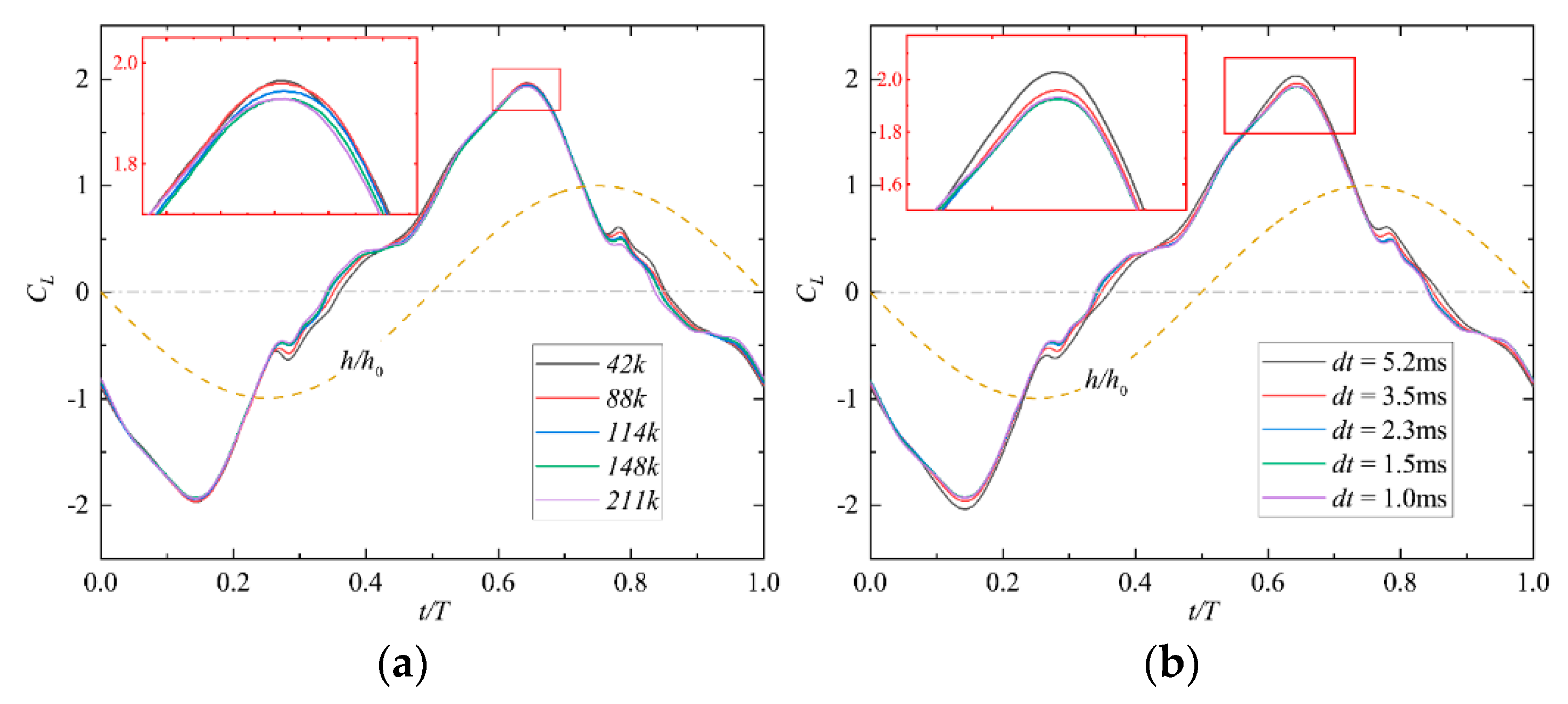
To assess the mesh dependency of the numerical results, Figure 4 compares the power coefficients of different mesh configurations under the condition of U* = 4.4, H0 = 1.4, θ0 = 20°, φ = 90°, and Re = 1100. Five sets of mesh resolutions with 120, 180, 210, 240, and 300 nodes around the foil, corresponding to 4.2 × 10⁴, 8.8 × 10⁴, 11.4 × 10⁴, 14.8 × 10⁴, and 21.1 × 10⁴ cells, were taken into consideration for comparison. As shown in Figure 4, the CL curve for 240 nodes is well coincident with that for 300 nodes. In addition, the same process was conducted to assess the time step dependency with 1.0, 1.5, 2.3, 3.5, and 5.2 ms. It is found in Table 1 that the deviations of the maximum lift coefficient for 14.8 × 10⁴ cells and and 2.3 ms from the finer configurations are under 0.5%, so a time step of 2.3 ms and mesh size of 14.8 × 10⁴ cells is sufficient for temporal and mesh accuracy.
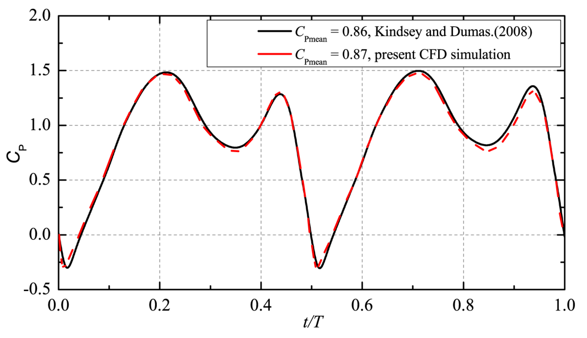
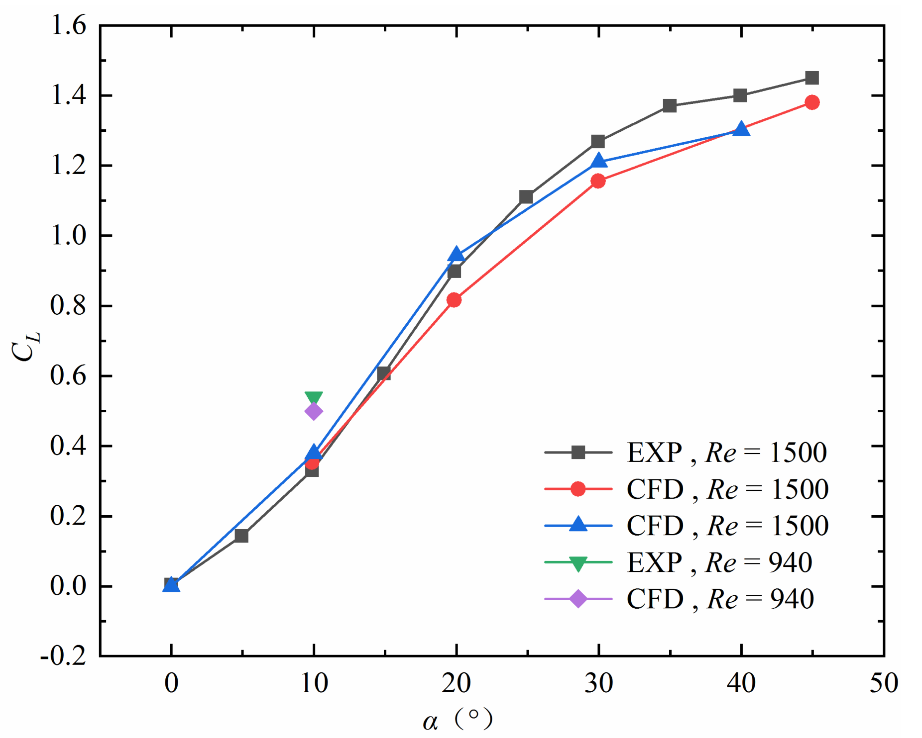
The reliability of the present well-established numerical method for fully passive oscillating-foil simulation has been fully verified in previous work [27,29]. The predicted power coefficient and lift coefficient showed good agreement with published numerical and experimental results, as shown in Figure 5 and Figure 6.

3. Results and Discussions

3.1. Prescribed Single-DOF Plunging Oscillation

The single-DOF oscillation energy convertors are simple in construction and thus have a significant advantage in manufacturing cost compared to the double-DOF convertors. The single-DOF bent plate with prescribed plunging motion is studied first to obtain the potential or limiting energy extraction performance of this convertor, which can guide us choose the optimal structural parameters for the fully passive convertor and check how far the performance of the fully passive convertor is from its limiting. Figure 7a,b present the variations of the power coefficient and efficiency with the reduced speed and the plunging amplitude. It can be observed from the figure that when the reduced speed is too small, the energy harvesting efficiency is negative, and thus the convertor is in a state of power consumption. With the increasing reduced speed, both the energy harvesting efficiency and power coefficient increase rapidly. Near the optimal reduced speed, the performance curve presents an inverted U-shaped distribution, indicating good adaptation to speed change under optimal or design conditions. With the further increasing reduced speed, the energy harvesting performance gradually approaches zero. In the explored range of plunging amplitude (1.0c–4.0c), the maximum efficiencies at different reduced velocities first increase, reaching a global maximum efficiency of 29.6% at a plunging amplitude of 3.5c, and then decrease.
As opposed to that of a double-DOF flapping foil (1.0c), the optimal plunging amplitude of the single-DOF bent plate (3.5c) is much larger. The fundamental reason for the large plunging amplitude for the single-DOF plate lies in its lack of adjustment in the effective AOA through pitching motion. The single-DOF bent plate can only rely on the plunging motion to reduce the average effective AOA, which can be demonstrated by the variations of effective AOA with plunging amplitude in Figure 7c. It can be found that the average effective AOA increases with the increasingly reduced speed and decreases with the reduced plunging amplitude. According to [21], the optimal average effective AOA is around 20° for energy harvesting. Meanwhile, Kinsey’s results [30] demonstrated that the optimal reduced speed for the resonance of vortex-induced oscillation is around 7.2, where the VIV-based oscillators achieve the largest amplitude and thus energy output. Therefore, the energy harvesting efficiency reaches the maximum when the plunging amplitude is around 3.5c and the reduced speed is around 7.5. If the plunging amplitude is reduced to 1.0c, the optimal average effective AOA and the optimal reduced speed cannot be satisfied at the same time.
The above analysis indicates that the average effective AOA is a key factor in determining the energy harvesting performance. The camber of the bent plate can regulate the effective AOA from the geometrical respect. We compared the energy harvesting performance of the flat plate and bent plate. For the flat plate, the energy harvesting efficiency is negative across all tested reduced velocities and plunging amplitudes. For the sake of brevity, specific data are not presented here.
Figure 8 compares the variations of the lift coefficient, power coefficient, and plunging velocity for the flat and bent plates under the same reduced speed and plunging amplitude (U* = 7.5, H0 = 3.5c). One can note that the level of lift coefficient for the flat plate is very low, with an amplitude of 0.155, and the direction of the lift is opposite to the plunging velocity, resulting in a negative power coefficient. Obviously, this is because the aerodynamic force in the plunging direction of the vertical flat plate is caused by the viscous resistance. For the bent plate, it can be seen from the figure that the amplitude of the lift coefficient of the bent plate (1.61) is significantly larger than that of the flat plate. The lift and the plunging velocity of the bent plate are synchronous most of the time, so the power coefficient of the bent plate is positive and the fluid energy can be harvested.
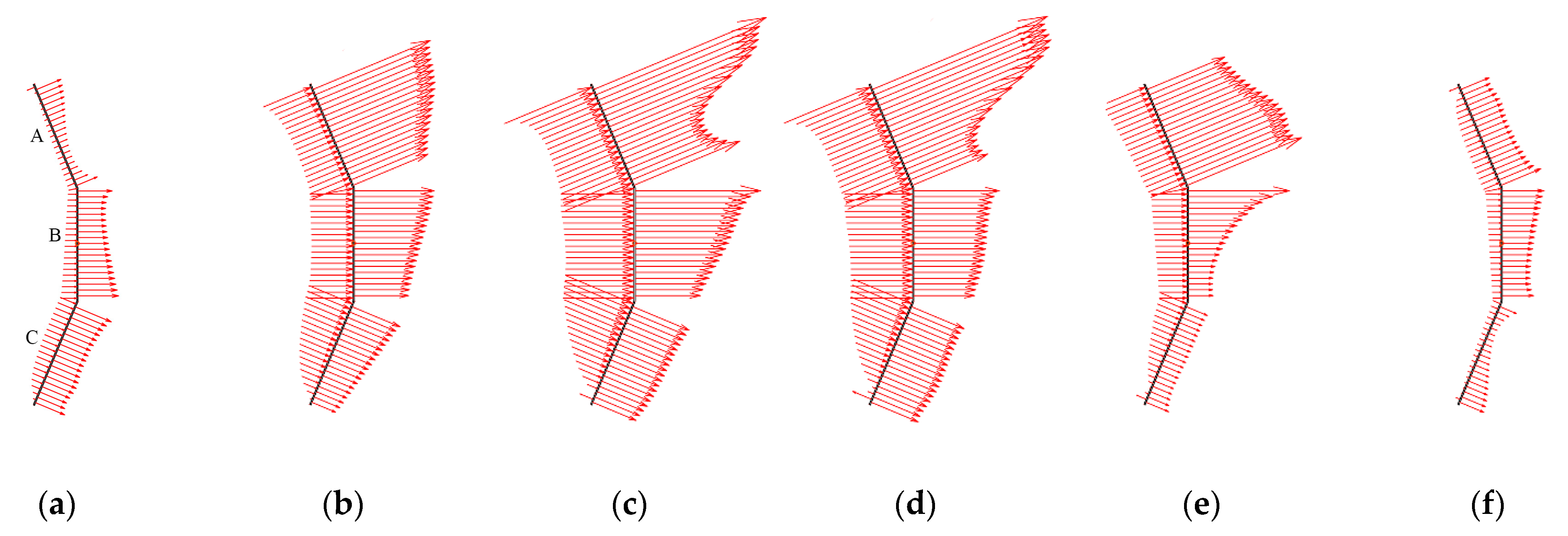
To better explain the larger lift force of the bent plate, Figure 9 depicts the variation of the aerodynamic pressure distribution on the surface of the bent plate during the half oscillating cycle. In the upstroke, the resultant force in the Y direction of the bent plate is upward on the whole, and the positive lift drives the upward motion. The plate is divided into three sections: A, B, and C. For A and C segments, the combined force of the pressure on the windward and leeward sides is directed from the windward side to the leeward side, so the lift on section A is positive, and the lift on section C is negative. The combined force on Section B is parallel to the incoming flow, so the corresponding lift is zero. Obviously, the pressure and the resulting lift on section A are greater than those on section C during most of the time of the upstroke, so the resultant force in the Y direction of the bent plate is generally upward.
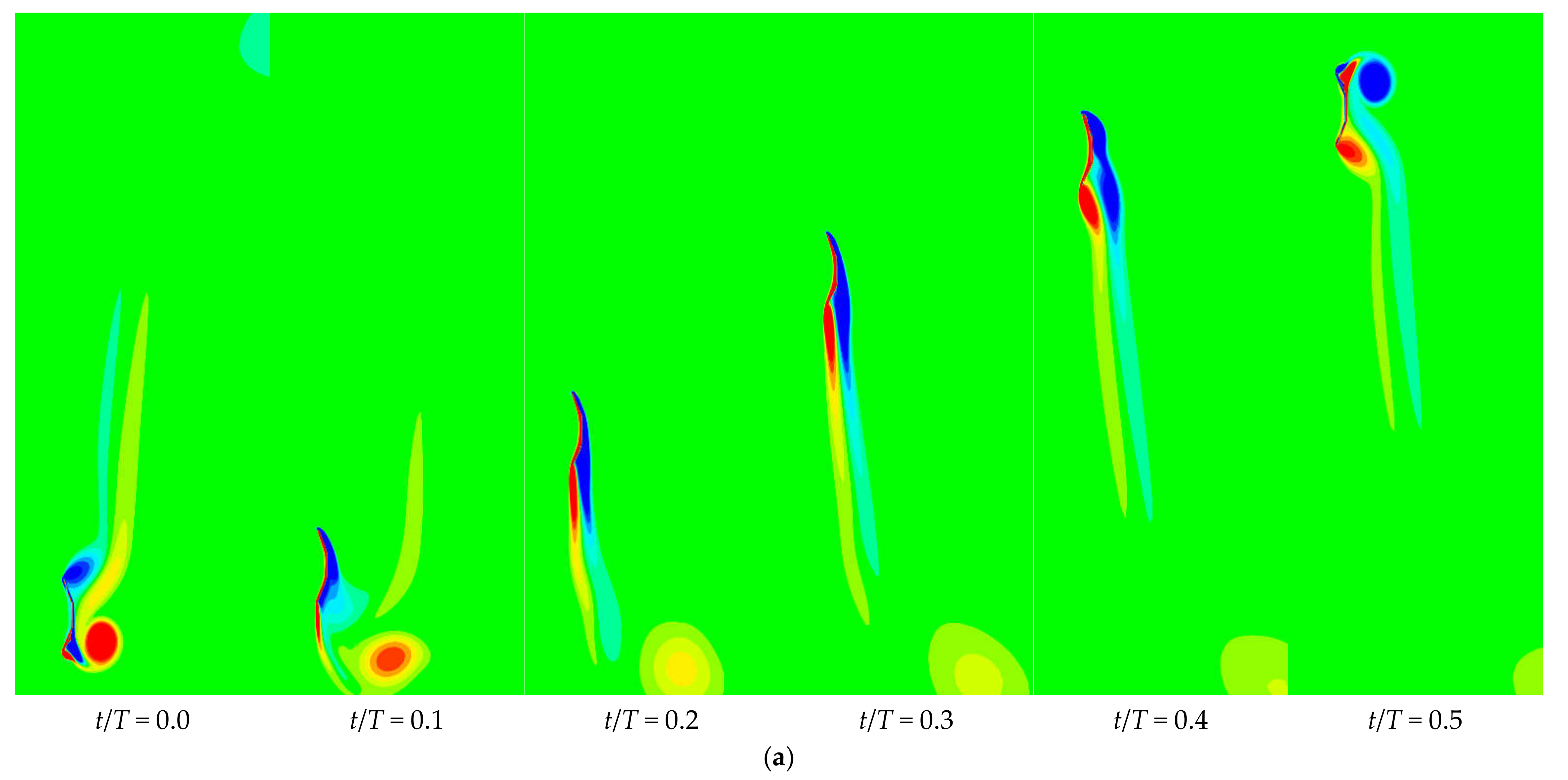
As the pressure is positive on the windside and negative on the leeside, the pressure gradient is favorable on the windside and adverse on the leeside. The adverse pressure gradient on the leeside of section A is the largest, indicating a large range of flow separation there, which can be confirmed from the vorticity contours afterward. The upper edge vortex near the leeside of section A forms a strong low-pressure zone, contributing to the positive lift on section A and thus the positive lift of the bent plate. Therefore, the strength of the upper edge vortex determines the overall energy harvesting performance.
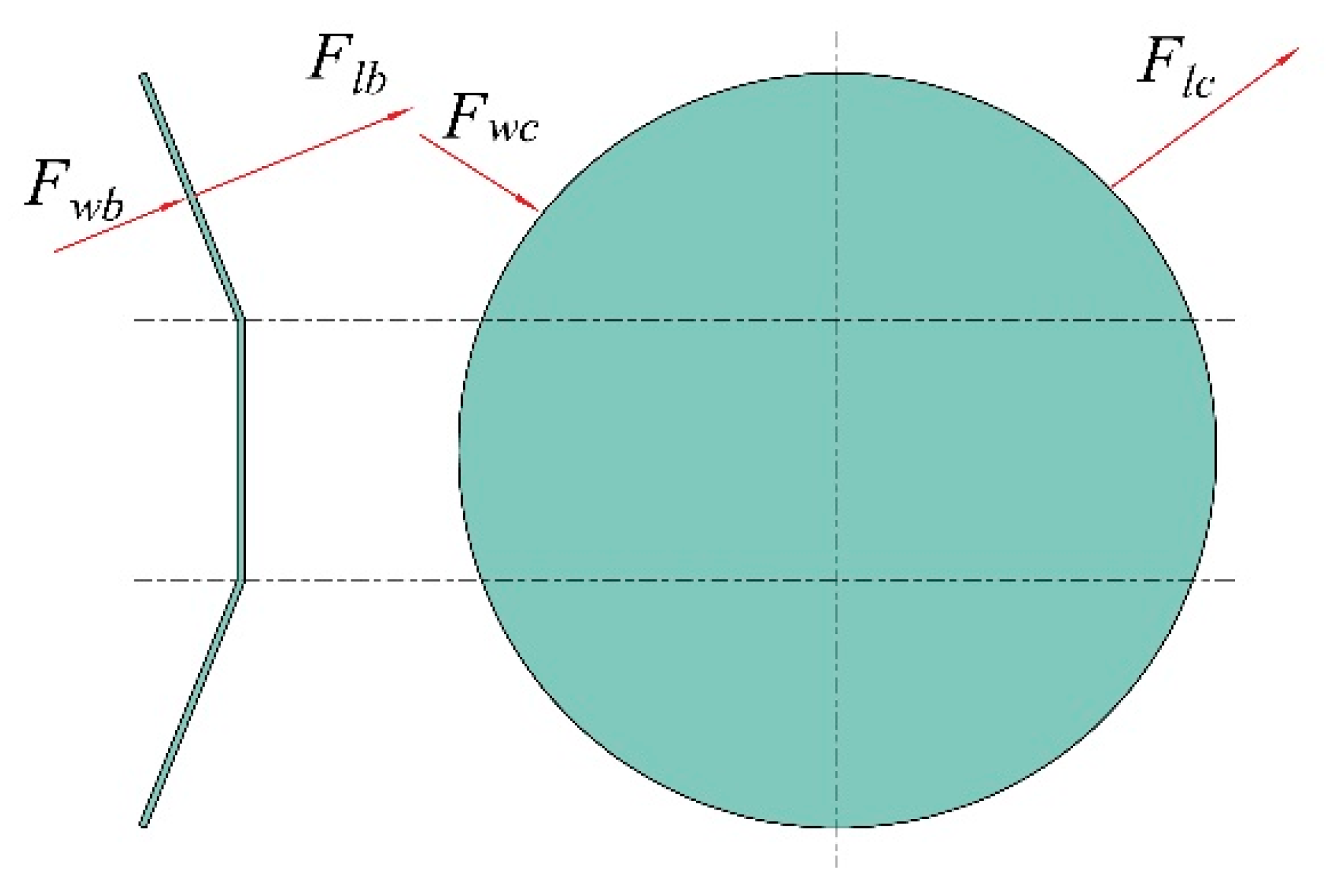
From the above results and analysis, it can be concluded that only slightly bending the two ends of the plate to the direction of the incoming flow can significantly change its aerodynamic characteristics and enable its potential for energy harvesting. At a suitable reduced speed, its energy harvesting efficiency and power coefficient can reach 29.6% and 2.36. Obviously, the bent plate outperforms other single-DOF oscillating energy harvesting systems (such as cylinders). It is believed that the better performance of the bent plate is due to the wing-like cross-sectional shape. To explain the better energy extraction performance of the bent plate, a schematic diagram of force analysis for the bent plate and cylinder is presented in Figure 10; according to Figure 9 and [31], both the pressure on the windside and leeside of section A are beneficial to increase the lift of the bent plate. In other words, since the normal directions of the windward surface and the leeward surface are inconsistent for bluff bodies (cylinders), the corresponding pressures on two sides (Fwc and Flc) are also inconsistent and cancel each other out, causing less lift and worse energy harvesting performance.

3.2. Prescribed Double-DOF Combined Plunging and Pitching Oscillation

When single-DOF motion is adopted, the variation of AOA of the bent plate can only be controlled by the plunging amplitude and frequency. We can also further control and thus optimize the variation of AOA through the pitching motion. When the pitching motion is involved, we can adjust the AOA pattern by changing the pitching amplitude and the phase between pitching and plunging motions. Previous studies have demonstrated that the 90° phase shift is optimal, so the effect of the phase shift is not further explored here. Figure 11 depicts the contour maps of efficiency in the two-dimensional space composed of the reduced speed and pitching amplitude for plunging amplitudes of 1.0, 1.4, and 1.8. Obviously, the efficiency possesses a unimodal distribution in the two-dimensional space; that is, there is only one optimal combination of the reduced speed and the pitching amplitude to maximize the efficiency of energy harvesting.
Table 2 lists the maximum efficiency and power coefficient of the bent plate in the two-dimensional space under different plunging amplitudes and their corresponding optimal pitching amplitude and reduced speed. It can be seen from the table that under different plunging amplitudes, the optimal pitching amplitude and reduced speed corresponding to the maximum efficiency and maximum power coefficient are the same. The reason is that the swept area of the oscillating bent plate under different motion parameters is d = 2H0 + c, so the swept area is independent of the reduced speed and pitching amplitude.
Comparing Figure 11a–c, it can be found that with the increase of the plunging amplitude, the maximum efficiency first increases and then decreases, reaching the maximum value of 37.4% at 1.4. The optimal pitching amplitude under different plunging amplitudes remains basically unchanged at about 15°, while the corresponding optimal reduced speed increases. The reason is that the plunging velocity is jointly determined by the plunging amplitude and the reduced speed. To keep the maximum plunging velocity and thus plunging-induced AOA at the optimal value, the reduced speed and the plunging amplitude should change synchronously. When the average AOA is too small, the separation vortex has a long attachment time but low intensity. Otherwise, the separation vortex is strong, but the attachment time is short. The oscillation period must match the average AOA to ensure that a larger separation vortex is attached to the plate for a longer relative time. In Figure 11, we also notice that when the pitch angle is equal to 0, flow energy can still be harvested, and the bent plate only has one DOF. However, the energy harvesting efficiency reached a maximum of 24.9%, which has not reached the maximum value of the single-DOF bent plate (29.6%).
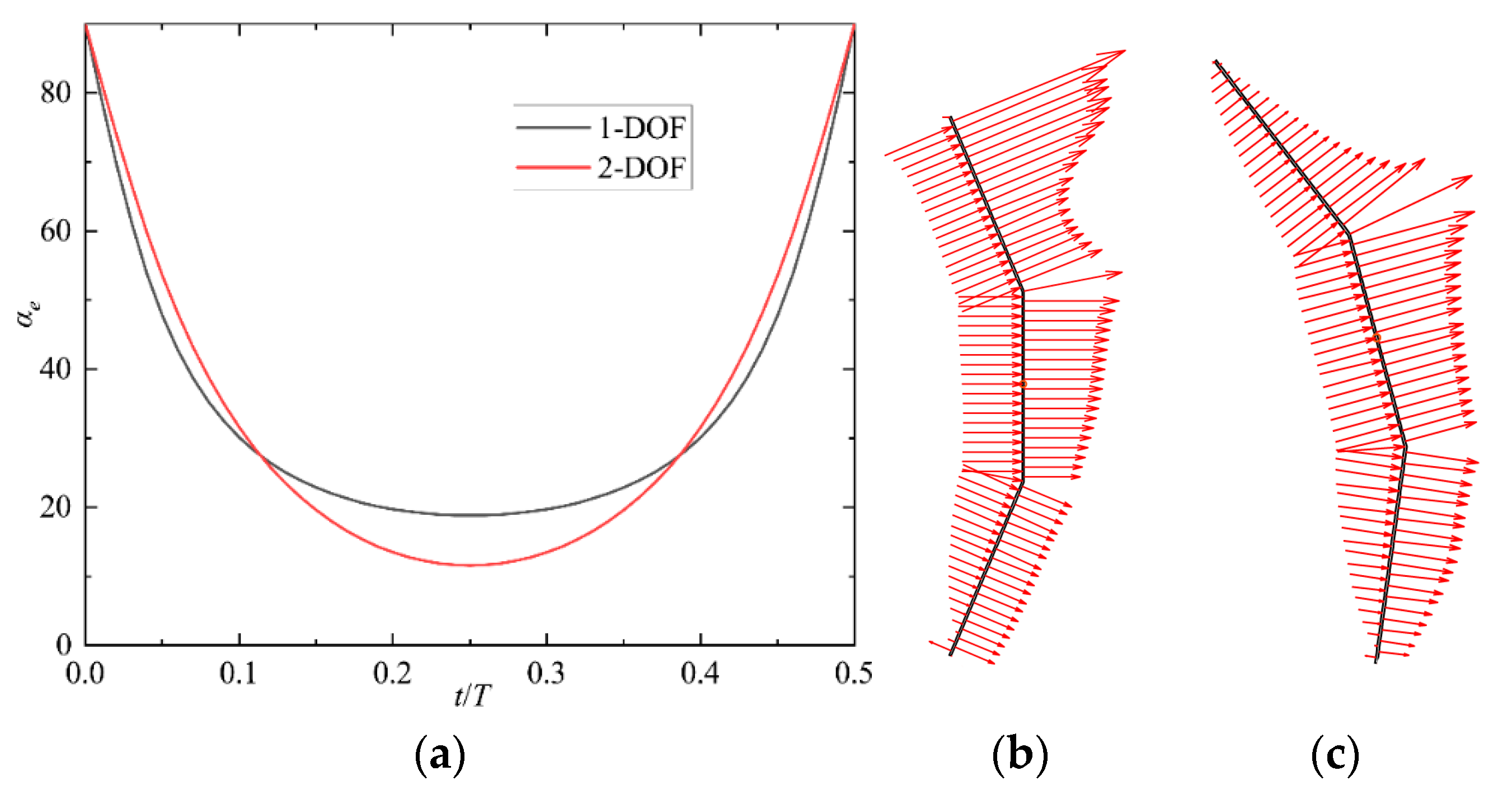
The better energy harvesting performance of the double-DOF bent plate can be explained with the variation pattern of the effective AOA. Figure 12a compares the variations of the effective AOA in half cycles under the optimal conditions of single and double DOFs. The average effective angles of attack are 34.3 and 35.2, respectively, which are very close to each other. The main difference of the variation curve of effective AOA lies in the minimum effective AOA: the minimum effective AOAs for single-DOF and double-DOF are 11.6 and 18.8, respectively. Therefore, it can be deduced that the reason for the higher efficiency of double-DOF lies in the fact that the variation pattern of effective AOA is better controlled by the pitching motion, so that the average effective AOA is maintained near the optimal AOA while the minimum effective AOA is reduced. Figure 12b,c further compare the pressure distribution of the single-DOF and double-DOF at t/T = 0.25, where the foils are at the middle of the upstroke. As illustrated in Figure 9, only the pressure on A segment produces upward lift in the case of single-DOF. For double-DOF, the foil contrarotates so that both the A and B segments produce upward lift; meanwhile, the downward lift on the C segment is much smaller compared to that of single-DOF, which can further explain the better energy harvesting performance of the double-DOF.
Although the maximum energy harvesting efficiency of the double DOF bent plate (37.4%) is 26.4% higher than that of single-DOF (29.6%), the double DOF requires a complex actuator to control its pitching motion, and the cost of manufacturing and maintenance is much higher than that of the single DOF. Therefore, the single-DOF bent plate is selected for the further development of the FIV-based bent-plate converter. Nevertheless, the new data and physical insights of the prescribed 2DOF provided in this work should stimulate further investigations and help to guide the design and testing of actual power-extraction systems based on the bent-plate concept, targeting the harvesting of high-grade flow energy.

3.3. Flow-Induced Single-DOF Plunging Oscillation

The theoretical energy harvesting efficiency of the single-DOF oscillating bent plate can reach nearly 30%. However, this efficiency is achieved under the specified trajectory of plunging motion, so it is questionable whether the bent plate can passively achieve this efficiency under the drive of stream. For this reason, this section searches for the best energy harvesting performance of the bent plate in passive motion mode. Figure 13 shows the variations of the energy harvesting efficiency and power coefficient of the bent plate with the mass-damping parameters at different reduced velocities. Very similar trends are observed for different reduced velocities. The efficiency first increases gently with the increasing mass-damping parameter and then decreases sharply to a lower value after reaching the maximum value. When the mass-damping parameter is less than or equal to 0.7, the efficiency increases with the reduced speed. When the mass-damping parameter is between 0.8 and 0.9, the efficiency increases first and then decreases as the reduced speed increases and reaches its maximum at the reduced speed of 7. In the range of parameters explored, the maximum efficiency is 29.3%, which is very close to the value of 29.6% for the bent plate under the prescribed motion. The optimal mass-damping parameter corresponding to the maximum efficiency is 0.9, and the optimal reduced speed is 7, which is close to the optimal value obtained in previous studies. Under this reduced speed, the aerodynamic damping reaches the minimum value (negative value), and the amplitude of vortex-induced vibration reaches the maximum.
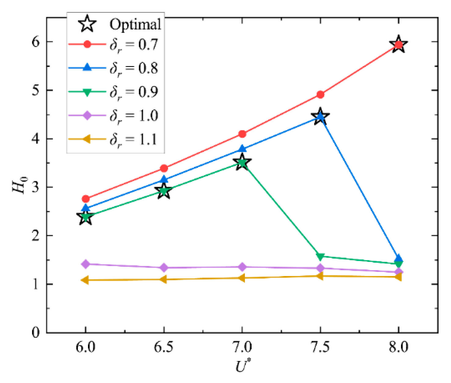
Figure 14 presents the variations of the bent plate’s oscillating amplitude with the reduced speed under different mass-damping parameters. Obviously, a larger mass-damping parameter leads to a smaller plunging amplitude. It is interesting to find that when the damping exceeds a critical value, no matter how large the reduced speed is, the amplitude is limited to less than 1.5c. The asterisks in the figure indicate the amplitude corresponding to the maximum efficiency at different reduced velocities. The optimal amplitude corresponding to the reduced speed of 7 is 3.51c, which is very close to the optimal amplitude of 3.5c obtained by the bent plate with the prescribed motion. We further compare the motion curves of the prescribed and passive motions under maximum efficiency conditions in Figure 15. It can be found that the motion curve of passive motion is very close to that of prescribed motion, indicating that the passive motion trajectory of the passive bent plate can be close to the ideal sinusoidal motion by choosing the reasonable dynamic parameters of the passive bent-plate convertor with single-DOF to achieve energy harvesting efficiency with the prescribed motion.
To explore the reason for the sharp drop of efficiency in Figure 13, Figure 16 compares the historical lift coefficient and plunging velocity of the bent plate in one cycle period at the reduced speed of 7 and the mass-damping parameters of 0.9 (large amplitude case) and 1.0 (small amplitude case), respectively. It can be observed from the figure that the curves of the plunging velocity in both cases are approximately sinusoidal, which conforms to the expectation of the linear oscillator. The maximum lift coefficient of the large amplitude case (1.55) is much larger than that of the small amplitude (0.81). The small lift coefficient is due to the much larger average effective AOA. By comparing the lift curve, it can also be found that the lift coefficient of the large amplitude case has only one peak, while the small amplitude case has two peaks. In this paper, it is believed that this is caused by different vortex shedding modes. In the case of large amplitude, the up and down strokes shed one vortex respectively in one cycle, while in the case of small amplitude, the up and down strokes shed a pair of vortexes in one cycle. Different vortex shedding modes are the fundamental reason for the sudden drop in amplitude and performance when the mass damping parameter increases from 0.9 to 1.0. When the amplitude of the bent plate is less than a critical value Hc1, the vortex shedding mode is 2P; when the amplitude is greater than a critical value Hc2, the vortex shedding mode is 2S. The bent plate cannot oscillate with an amplitude between these two critical values. When the reduced velocity is 7.0, Hc1 is close to 1.36 and Hc2 is close to 3.51.
Mass-damping parameters of 0.9 and 1.0 are selected for detailed flow insight due to the sudden reduced plunging amplitude. Figure 17 depicts the evolution of the vorticity field in half-cycle (upstroke) for the cases of large and small plunging amplitudes. In the case of a large plunging amplitude, the upper-edge vortex (leading-edge vortex) is attached to the suction side during most of the stroke, and the low-pressure region formed by the upper-edge vortex brings a relatively larger lift force, which is generally accepted as being responsible for the large time-averaged lift force of low Reynolds number flapping flight [32,33]. At the end of the upper stroke (t/T = 0.5), the upper edge vortex sheds off, and the lower edge vortex forms. When the mass-damping parameter is set to 1.0, the upper edge vortex sheds off near t/T = 0.4, causing the departure of the corresponding low-pressure region from the plate surface and thus the lift valley near t/T = 0.4 as shown in the Figure 14. Between t/T = 0.4 and t/T = 0.5, a smaller upper edge vortex is produced, resulting in a small recovery of lift. In a word, when the mass-damping parameter is set at 0.9, the attachment of the upper edge vortex lasts longer, leading to a higher average lift coefficient and thus better energy harvesting performance.

4. Conclusions

The energy extraction performance of the one-DOF FIV-based flow energy convertors is limited due to its low lift and oscillating amplitude. The bluff shape of the oscillator is one major contributing factor. A FIV-based flow energy convertor with a bent plate as the oscillator is proposed to achieve a larger oscillating amplitude and thus better energy converting performance.
Three motion patterns, namely prescribed single-DOF plunging oscillation, prescribed double-DOF combined plunging and pitching oscillation, and flow-induced single-DOF plunging oscillation, are considered in this work. The energy extraction performance and dynamic response of prescribed motion patterns are assessed first to demonstrate its theoretical potential for energy extraction. The prescribed single-DOF bent plate can reach a maximum efficiency of 29.6% and power coefficient of 2.36 at a relative plunging amplitude of 3.5, while the double-DOF bent plate achieves a maximum efficiency of 37.4% and power coefficient of 1.42 at a smaller amplitude of 1.4. It is found that the average effective AOA is one key factor in determining energy harvesting performance, and the camber of the bent plate regulates the effective AOA from the geometrical respect, while the pitching motion can adjust the effective AOA more directly and actively.
The flow-induced single-DOF plunging oscillation is then considered, and a new dynamical parameter, namely the mass-damping parameter, is introduced. The FIV-based single-DOF convertor can achieve an energy converting efficiency of 29.3%, and the corresponding optimal reduced velocity and resulting plunging amplitude are very close to that of the prescribed single-DOF plunging oscillation, indicating that the optimal active motion mode can be realized through the passive motion mode by appropriately choosing the dynamic parameters.
It can be concluded that only slightly bending the two ends of the plate to the direction of the incoming flow can significantly change its aerodynamic characteristics and enable its potential for energy harvesting. The bent plate possesses the advantages of low-mass, low cost, and high energy converting performance. It is believed that its high performance is due to the wing-like cross-sectional shape. The aerodynamic analysis demonstrates that both the pressure on the windside and leeside of the bent plate contributes to the larger lift and thus the larger oscillating amplitude and energy extraction performance.

Author Contributions

Conceptualization, W.J. and F.W.; methodology, W.J.; software, W.J. and Z.M.; validation, R.S.; formal analysis, W.J. and Z.M.; investigation, W.J. and R.S.; data curation, F.W.; writing—original draft preparation, W.J.; writing—review and editing, D.X.; visualization, W.J. and Z.M.; supervision, D.X.; project administration, W.J. All authors have read and agreed to the published version of the manuscript.

Funding

This research was funded by Natural Science Foundation of Hubei Province, grant number 2021CFB114, Open fund of State Key Laboratory of Clean Energy Utilization, grant number ZJUCEU2021012, and China Postdoctoral Science Foundation, grant number 2020M672411.

Institutional Review Board Statement

Not applicable.

Informed Consent Statement

Not applicable.

Data Availability Statement

Data is contained within the article.

Acknowledgments

The authors acknowledge the financial support by Youth Talent Promotion Project of Chinese Society of Electrical Engineering. The numerical simulations in this work have been done on the supercomputing system in the Supercomputing Center of Wuhan University.

Conflicts of Interest

The authors declare no conflict of interest.

Nomenclature

cFoil chord length, m
CDamping of the damper, N·s·m−1
CLLift coefficient
CPPower coefficient
CPmeanTime-averaged power coefficient
dVertical extent of the foil motion, m
fOscillation frequency, s−1
FyLift force, N
fNNatural frequency for oscillator, s−1
H0Plunging amplitude, m
KStiffness of the spring, N·m−1
MFoil mass, kg
mdDisplaced fluid mass, kg
m*Mass ratio
ReReynolds number
tPhysical time, s
TOscillating period, s
U*Reduced velocity
UFree stream velocity, m·s−1
VyPlunging velocity, m·s−1
wCamber height, m
y(t)Plunging motion, m
αeEffective angle of attack, °
βBending angle of the bent plate, °
δrMass-damping parameter
φPhase difference between the pitching and plunging motions, °
ηEnergy extraction efficiency
θ0Pitching amplitude, °
θ(t)Pitching motion, °

References

  1. Moriarty, P.; Honnery, D. Can renewable energy power the future? Energy Policy 2016, 93, 3–7. [Google Scholar] [CrossRef]
  2. Wei, C.; Jing, X. A comprehensive review on vibration energy harvesting: Modelling and realization. Renew. Sustain. Energy Rev. 2017, 74, 1–18. [Google Scholar] [CrossRef]
  3. Lee, Y.J.; Qi, Y.; Zhou, G.; Lua, K.B. Vortex-induced vibration wind energy harvesting by piezoelectric MeMS device in formation. Sci. Rep. 2019, 9, 1–11. [Google Scholar] [CrossRef] [PubMed]
  4. Abdelkefi, A. Aeroelastic energy harvesting: A review. Int. J. Eng. Sci. 2016, 100, 112–135. [Google Scholar] [CrossRef]
  5. Khalak, A.; Williamson, C.H. Investigation of relative effects of mass and damping in vortex-induced vibration of a circular cylinder. J. Wind Eng. Ind. Aerodyn. 1997, 69, 341–350. [Google Scholar] [CrossRef]
  6. Williamson, C.; Govardhan, R. Vortex-induced vibrations. Annu. Rev. Fluid Mech. 2004, 36, 413–455. [Google Scholar] [CrossRef] [Green Version]
  7. Govardhan, R.; Williamson, C. Critical mass in vortex-induced vibration of a cylinder. Eur. J. Mech. B Fluids 2004, 23, 17–27. [Google Scholar] [CrossRef]
  8. Govardhan, R.; Williamson, C. Resonance forever: Existence of a critical mass and an infinite regime of resonance in vortex-induced vibration. J. Fluid Mech. 2002, 473, 147–166. [Google Scholar] [CrossRef]
  9. Govardhan, R.; Williamson, C. Modes of vortex formation and frequency response of a freely vibrating cylinder. J. Fluid Mech. 2000, 420, 85–130. [Google Scholar] [CrossRef]
  10. Raghavan, K.; Bernitsas, M.M. Experimental investigation of Reynolds number effect on vortex induced vibration of rigid circular cylinder on elastic supports. Ocean Eng. 2011, 38, 719–731. [Google Scholar] [CrossRef]
  11. Li, T.; Ishihara, T. Numerical study on vortex-induced vibration of circular cylinder with two-degree-of-freedom and geometrical nonlinear system. J. Fluids Struct. 2021, 107, 103415. [Google Scholar] [CrossRef]
  12. Bernitsas, M.M.; Raghavan, K.; Ben-Simon, Y.; Garcia, E.M.H. VIVACE (Vortex Induced Vibration Aquatic Clean Energy): A New Concept in Generation of Clean and Renewable Energy from Fluid Flow. J. Offshore Mech. Arct. Eng. 2008, 130, 041101. [Google Scholar] [CrossRef]
  13. Bernitsas, M.M.; Ben-Simon, Y.; Raghavan, K.; Garcia, E. The VIVACE converter: Model tests at high damping and Reynolds number around 105. J. Offshore Mech. Arct. Eng. 2009, 131, 011102. [Google Scholar] [CrossRef]
  14. Ding, L.; Zhang, L.; Bernitsas, M.M.; Chang, C.-C. Numerical simulation and experimental validation for energy harvesting of single-cylinder VIVACE converter with passive turbulence control. Renew. Energy 2016, 85, 1246–1259. [Google Scholar] [CrossRef] [Green Version]
  15. Zhang, L.; Abdelkefi, A.; Dai, H.; Naseer, R.; Wang, L. Design and experimental analysis of broadband energy harvesting from vortex-induced vibrations. J. Sound Vib. 2017, 408, 210–219. [Google Scholar] [CrossRef]
  16. Hover, F.; Techet, A.; Triantafyllou, M. Forces on oscillating uniform and tapered cylinders in a crossflow. J. Fluid Mech. 1998, 363, 19. [Google Scholar] [CrossRef] [Green Version]
  17. Barrerogil, A.; Pindado, S.; Avila, S.G. Extracting energy from Vortex-Induced Vibrations: A parametric study. Appl. Math. Model. 2012, 36, 3153–3160. [Google Scholar] [CrossRef] [Green Version]
  18. Ding, L.; Zhang, L.; Wu, C.; Mao, X.; Jiang, D. Flow induced motion and energy harvesting of bluff bodies with different cross sections. Energy Convers. Manag. 2015, 91, 416–426. [Google Scholar] [CrossRef]
  19. Zhang, B.; Song, B.; Mao, Z.; Tian, W.; Li, B. Numerical investigation on VIV energy harvesting of bluff bodies with different cross sections in tandem arrangement. Energy 2017, 133, 723–736. [Google Scholar] [CrossRef]
  20. Dai, H.; Abdelkefi, A.; Wang, L. Piezoelectric energy harvesting from concurrent vortex-induced vibrations and base excitations. Nonlinear Dyn. 2014, 77, 967–981. [Google Scholar] [CrossRef]
  21. Kinsey, T.; Dumas, G. Optimal operating parameters for an oscillating foil turbine at Reynolds number 500,000. AIAA J. 2014, 52, 1885–1895. [Google Scholar] [CrossRef]
  22. Veilleux, J.-C.; Dumas, G. Numerical optimization of a fully-passive flapping-airfoil turbine. J. Fluids Struct. 2017, 70, 102–130. [Google Scholar] [CrossRef]
  23. Jiang, W.; Wang, Y.L.; Zhang, D.; Xie, Y.H. Numerical investigation into power extraction by a fully passive oscillating foil with double generators. Renew. Energy 2019, 133, 32–43. [Google Scholar] [CrossRef]
  24. Boudreau, M.; Dumas, G.; Rahimpour, M.; Oshkai, P. Experimental investigation of the energy extraction by a fully-passive flapping-foil hydrokinetic turbine prototype. J. Fluids Struct. 2018, 82, 446–472. [Google Scholar] [CrossRef]
  25. Jiang, W.; Wang, Y.; Zhang, D.; Xie, Y. Numerical investigation into the energy extraction characteristics of 3D self-induced oscillating foil. Renew. Energy 2020, 148, 60–71. [Google Scholar] [CrossRef]
  26. Jiang, W.; Zhang, D.; Xie, Y.H. Numerical investigation into energy extraction from self-induced oscillations of an elliptical plate. J. Fluids Struct. 2017, 69, 1–15. [Google Scholar] [CrossRef]
  27. Jiang, W.; Zhang, D.; Xie, Y.H. Numerical investigation into the effects of arm motion and camber on a self-induced oscillating hydrofoil. Energy 2016, 115 Pt 1, 1010–1021. [Google Scholar] [CrossRef]
  28. Bos, F.M.; Lentink, D.; Van Oudheusden, B.W.; Bijl, H. Influence of wing kinematics on aerodynamic performance in hovering insect flight. J. Fluid Mech. 2008, 594, 341–368. [Google Scholar] [CrossRef] [Green Version]
  29. Jiang, W.; Mei, Z.Y.; Wu, F.; Han, A.; Xie, Y.H.; Xie, D.M. Effect of shroud on the energy extraction performance of oscillating foil. Energy 2022, 239, 122387. [Google Scholar] [CrossRef]
  30. Kinsey, T.; Dumas, G. Parametric study of an oscillating airfoil in a power-extraction regime. AIAA J. 2008, 46, 1318–1330. [Google Scholar] [CrossRef]
  31. Zasso, A.; Belloli, M.; Giappino, S.; Muggiasca, S. On the pressure and force field on a circular cylinder oscillating in the lock-in region at sub-critical Reynolds number. In Proceedings of the ASME Pressure Vessels and Piping Conference, Vancouver, BC, Canada, 23–26 July 2006; pp. 919–927. [Google Scholar]
  32. Ho, S.; Nassef, H.; Pornsinsirirak, N.; Tai, Y.-C.; Ho, C.-M. Unsteady aerodynamics and flow control for flapping wing flyers. Prog. Aerosp. Sci. 2003, 39, 635–681. [Google Scholar] [CrossRef]
  33. Sane, S.P. The aerodynamics of insect flight. J. Exp. Biol. 2003, 206, 4191–4208. [Google Scholar] [CrossRef] [PubMed] [Green Version]
Figure 1. Evolution of the oscillator’s sectional shape.
Energies 15 01606 g001
Figure 2. Schematic of the prescribed double-DOF bent plate and the flow-induced single-DOF oscillator based on a bent plate. (a) Prescribed motion (b) Passive motion.
Energies 15 01606 g002
Figure 3. Mesh details and boundary conditions. The Inner Zone contains 10.5 × 10⁴ elements with first layer element height of 2 × 10⁻³ chord length, and the Outer Zone contains 4.3 × 10⁴ elements.
Energies 15 01606 g003
Figure 4. Variations of CL in one cycle for five sets of mesh and time step resolutions. (a) Mesh dependency. (b) Time step dependency.
Energies 15 01606 g004
Figure 5. Time evolution of total power coefficient CP at Re = 1100 [27].
Energies 15 01606 g005
Figure 6. Comparison of the lift coefficient variation for the wings with AOA at Re of 940 and 1500 [29].
Energies 15 01606 g006
Figure 7. Variations of the power coefficient, efficiency, and αe with reduced velocity and plunging amplitude. (a) Power coefficient. (b) Energy extraction efficiency. (c) Effective AOA.
Energies 15 01606 g007
Figure 8. Variations of lift coefficient, power coefficient, and plunging velocity in one cycle for flat and bent plates.
Energies 15 01606 g008
Figure 9. Variation of the aerodynamic pressure distribution on the surface of the bent plate in half cycle. (a) t/T = 0.0. (b) t/T = 0.1. (c) t/T = 0.2. (d) t/T = 0.3. (e) t/T = 0.4. (f) t/T = 0.5.
Energies 15 01606 g009
Figure 10. Schematic force analysis on the corresponding section of the bent plate and typical bluff body.
Energies 15 01606 g010
Figure 11. Contour maps of efficiency in the two-dimensional space composed of the reduced speed and pitching amplitude. (a) H0 = 1.0. (b) H0 = 1.4. (c) H0 = 1.8.
Energies 15 01606 g011
Figure 12. Comparison of 1 and 2-DOF oscillating bent plates in effective AOA and pressure distribution. (a) Variations of αe in half cycle. (b) Pressure distribution of 1-DOF. (c) Pressure distribution of 2-DOF.
Energies 15 01606 g012
Figure 13. Variations of energy harvesting efficiency and power coefficient of the bent plate with the mass-damping parameter at different reduced velocities. (a) Energy harvesting efficiency. (b) Power coefficient.
Energies 15 01606 g013
Figure 14. Variations of the oscillating amplitude with the reduced speed and mass-damping parameters.
Energies 15 01606 g014
Figure 15. Motion curves of the prescribed and passive motions under maximum efficiency conditions.
Energies 15 01606 g015
Figure 16. Historical lift coefficient and plunging velocity at different mass-damping parameters.
Energies 15 01606 g016
Figure 17. Evolution of the vorticity field in half-cycle for cases of large and small plunging amplitudes. (a) mass-damping parameter of 0.9, large amplitude. (b) mass-damping parameter of 1.0, small amplitude.
Energies 15 01606 g017aEnergies 15 01606 g017b
Table 1. Deviations of maximum lift coefficient for different mesh and time step configurations.
Mesh Size, CellsTime Step, msCLmaxδ, %
14.8 × 1041.02.0284.94
1.51.9581.35
2.31.929−0.16
3.51.925−0.36
5.21.932-
4.2 × 1042.31.9651.85
8.8 × 1041.9591.57
11.4 × 1041.9440.79
14.8 × 1041.9290.01
21.1 × 1041.929-
Table 2. Deviations of maximum lift coefficient for different mesh and time step configurations.
H0U*θ0ηmaxU*θ0CPmax
1.03.51533.8%3.5151.02
1.44.41537.4%4.4151.42
1.85.01534.9%5.0151.61
Publisher’s Note: MDPI stays neutral with regard to jurisdictional claims in published maps and institutional affiliations.