1. Introduction
The use of the power electronic (PE) converters is now widespread in the world, including domestic and industry power supplies, motor drives, and emerging applications such as renewables, energy storage, hybrid and electrical vehicles, etc. [
1]. Such ubiquitous penetration of PE in all segments of modern industry increases certain unwanted occurrences regarding power quality (PQ) in the AC power grid, as presented, for example, in [
2,
3]. These occurrences are the consequences of three main issues. The first issue is nonlinearity of the switching components, which results in a distorted current (current with higher-order harmonic content) that is directly related to the appearance of higher voltage harmonics in the AC network [
4]. The second issue is related to the commutation of the converter components, which results in periodic voltage dips [
5]. Finally, the third issue is the appearance of even-order harmonics in half-controlled rectifiers, which can result in asymmetry of the AC voltage (e.g., DC magnetic bias phenomenon in AC transformers) [
6]. Furthermore, issues regarding PQ require careful study and monitoring of the impact of each disturbance type produced by PE converters [
7]. Most DC loads are connected to the power grid using some type of PE converter. If the observed energy flow is from the AC grid to the DC load, the commonly used converters are AC to DC converters, also commonly known as rectifiers. Among all types of PE converters, these produce most noticeable current harmonics, which may reflect the RMS value of the phase voltage, thus creating potential PQ problems in the AC grid [
1]. According to [
8], this type of converters can be classified into two major groups according to the phase number (with single-phase and three-phase being the most common) and the output voltage waveform (half-wave or full-wave). Furthermore, rectifiers can be classified as uncontrolled (diode) rectifiers, semiconverters (half-controlled phase rectifiers), and phase-controlled (fully controlled) rectifiers.
Uncontrolled rectifiers have a fixed output voltage and are the simplest rectifiers as they do not need any additional control circuit for operation. Semiconverters consist of a combination of diodes and thyristors, while phase-controlled rectifiers have only thyristors [
9,
10]. The output voltage of these converters can be controlled via gate control by changing the fire angle of the thyristor [
11]. Compared to a phase-controlled rectifier, the complexity and cost of a control circuit can be greatly reduced for semiconverters, mostly due to implementation of a simpler control logic. Therefore, semiconverters may be more attractive in applications where only a single quadrant operation is required and where feed of industrial loads up to several hundred kilowatts is needed [
12]. However, semiconverters have some drawbacks regarding feedback influence on the AC power grid. In particular, semiconverters generate an excessive amount of even-order current harmonics, which are injected into the AC power grid, the effects of which are unwanted as many research papers have stated [
13,
14,
15,
16,
17,
18,
19,
20,
21]. For example, when semiconverters were first introduced to industries, Duff and Ludbrook presented [
13] the problems associated with them being used in high-power DC armature applications. Zander [
14] presented the problem of reactive power production by thyristor rectifiers used in electrical drives. Smith and Stratford [
15] presented the problem of current harmonic injection to the power grid in specific cement plant facilities where thyristor rectifiers were utilized.
The issue of even-order harmonic generation associated with semiconverters has also been investigated and presented in a few research papers. Tang and Melhorn [
12] discussed the basics of even-order harmonic generation by semiconverters. The same problem was presented by Mansoor et al. [
16] with a case study of multiple semiconverters used as heater drives in one industrial facility. Buddingh [
17] discussed how even-order current harmonics (in this case mainly the fourth) in the power grid can cause the unusual problem of even harmonic resonance. Problems regarding current harmonic spectrum and the second harmonic, which is studied in the present paper, are given in [
18,
19,
20,
21]. The effects of semiconverters on the AC grid are so significant that Orr and Emanuel [
21] recommended restriction (or even a ban) of semiconverter use in industries.
Even-order current harmonics produced by semiconverters can be reduced to some extent through the implementation of PWM, as presented in [
22], or by installing some sort of filtering on the AC side, as presented in [
23]. However, the problem here is the price of the technical solution, which can easily exceed the price of using different kinds of PE converters. Although the use of semiconverters today is greatly reduced (largely due to DC motors being replaced by AC motors), they are still in use in some form, as noted, for example, in [
24,
25,
26,
27,
28,
29,
30,
31]. Apart from industrial applications, semiconverters can be used for research purposes where harmonics (especially the second) are of interest. One such example is the work by Goh et al. [
20], where semiconverters were used to investigate the issue of voltage flicker.
In this study, a procedure is proposed that identifies the occurrence of harmonic order in phase current (without conducting spectral analysis measurements) based on mutual comparison of phase voltage and current. The
u–i characteristic is introduced as an easily applicable way of presenting the measurement results, with the shape and position in the phase plane indicating the evenness/oddness of phase current harmonics. The unilateral or bilateral property of the
u–i characteristic can be related to the order of appearance of current harmonics, while the described
u–i characteristic area can be linked to the reactive power produced. The
u–i characteristic is not a new concept. It is generally used in network theory to determine the properties of network elements, especially dissipative elements (e.g., nonlinearity/linearity, passivity/activity, etc.) [
32]. However, in rectifiers, the
u–i characteristic can be used as a PQ indicator. According to the reviewed literature, the
u–i characteristic has not been utilized in harmonic identification so far.
The rest of the paper is organized into five sections. An introduction to the topic and literature review of semiconverter issues, starting from early research to today, is given in
Section 1. The mathematical model of an uncontrolled rectifier, which is used as a reference point to properly understand the
u–i characteristics of a semiconverter, is presented in
Section 2.
Section 3 presents an analysis of the mathematical model of a semiconverter. In
Section 4, analyses of the current harmonics, power components, and power factor are given. Laboratory measurements conducted on the real assembled uncontrolled rectifier and three-phase semiconverter are presented and discussed in
Section 5. Finally, concluding remarks are made in
Section 6.
2. Mathematical Model of an Uncontrolled Rectifier
To understand how a three-phase semiconverter operates and to have a reference point of u–i characteristics, it is essential to begin with analysis of a three-phase uncontrolled rectifier. The analysis of an uncontrolled rectifier is well known and given in most books dealing with this issue. Therefore, only the essential expressions and waveforms are given below to analyze the current harmonic spectrum, which is the main focus of this study.
The schematic of a three-phase uncontrolled rectifier is shown in
Figure 1. Here, the rectifier is connected to the AC power grid through a regulation transformer (
T;
Figure 1). An uncontrolled rectifier consists of diodes only, and it is thus uncontrollable in terms of changing the output values of DC voltage and current. For the purpose of analysis, it is assumed that the uncontrolled rectifier is connected to ideally symmetrical AC power grid with phase voltage defined as follows:
where
is the peak of the phase voltage, and
is the phase number. Three characteristic nodes are shown in
Figure 1, where 0 is the neutral point;
C is the cathode group of diodes
V1,
V3, and
V5; and
A is the anode group of diodes
V2,
V4, and
V6.
For the purpose of analysis, the resistance and inductance of the power supply has been ignored. Moreover, switching components are modeled as ideal diodes with instantaneous commutation between them. The load is defined as the current sink with the time constant defined as
. Here,
is inductance, and
is resistance of the load. Assuming that
, the current sink will maintain the current
smoothed with the current amount is as follows [
8]:
Taking into consideration all assumptions given above, the typical waveforms of the mathematical model of an uncontrolled rectifier can be created, as illustrated in
Figure 2.
As can be seen from
Figure 2, the uncontrolled rectifier has symmetrical waveforms of phase current covering half of the voltage period. Specifically, symmetry refers to the first zero instance of the corresponding phase voltage. This observation should be noted before the concept of mutual phase voltage and current display is introduced.
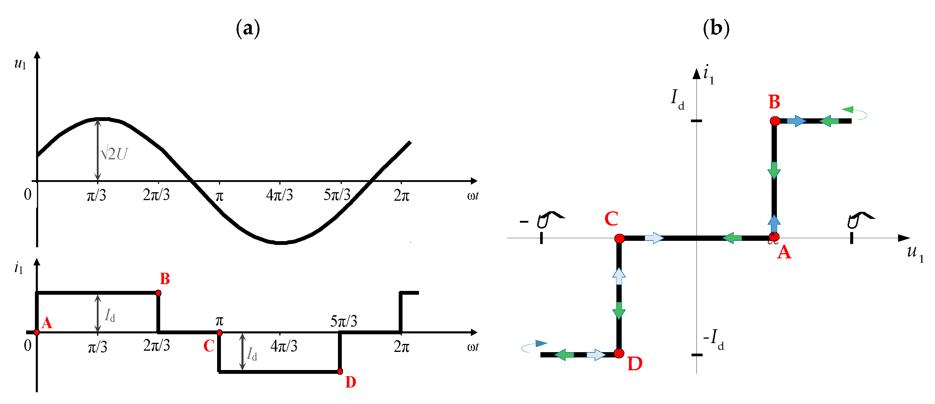
Concept of u–i Characteristic
The
u–i characteristic can be obtained if the characteristics of the current and voltage are shown in the phase plane. A typical
u–i characteristic (phase 1;
Figure 1), along with the corresponding waveforms of phase current and voltage, is shown in
Figure 3.
Here, selected significant points A–D on the
u–i characteristic (
Figure 3b) corresponds to the voltage and current waveforms (
Figure 3a). The starting point for analysis is A. The
u–i characteristic (
Figure 3b) is symmetrical and distinctly shaped with respect to the origin of the coordination system. This characteristic is also called bilateral.
Similarly, the same procedure of analysis can be applied on a fully controlled rectifier, where the property of bilateral characteristic is also valid.
3. Mathematical Model of a Semiconverter
A three-phase semiconverter (
Figure 4) consists of series combination of a controlled three-phase half-wave converter with common cathode (
C) and an uncontrolled half-wave rectifier with common anode (
A). The upper bridge is phase-controlled with thyristors (
V1,
V3, and
V5) as the main switching components, while the lower bridge is uncontrolled and is built with diodes (
V2,
V4, and
V6), as shown in
Figure 4. The thyristor is a three-terminal semiconductor device where the on-state can be controlled by the gate terminal, while the off-state is not controllable [
33]. When the gate signal is applied on a thyristor, the thyristor latches the current and stays in the on-state mode until the anode current falls below the holding point. Such control allows thyristors to be used in semiconverters as switching devices that can be turned on at a specific instant.
A firing (delay) angle
can easily be described as a delay between the instance when the diode would naturally start to conduct (if thyristors are replaced with diodes) and the instance where the thyristor actually starts to conduct [
11], as shown in
Figure 5. The schematic of a semiconverter is shown in
Figure 4. Due to mutual comparability, the semiconverter is connected to the AC power grid through a regulation transformer (
T;
Figure 4) in the same manner as an uncontrolled rectifier (
T;
Figure 1).
The switches of the common anode group
A are uncontrolled and basically act as a half-wave diode rectifier. In the model, the firing angle
of the semiconverter can be set anywhere between 0° and 180° [
8]. If the firing angle
is set to zero, semiconverter acts in the same manner as a diode rectifier. However, it is worth mentioning that, in practice, a firing angle
cannot be set to exactly zero due to the specific physical construction of a thyristor [
33]. This is the reason for using an uncontrolled rectifier in semiconverter analysis. Although there is a solution to this shortage in the form of original schematic modification, it is not carried out due to better model understanding and analysis. Nevertheless, if the thyristor is fired with firing angle greater than zero
, the semiconverter can work in two basic operational modes: three-pulse and six-pulse. The operational mode depends exclusively on the upper bridge thyristor control. The converter operates in six-pulse mode for firing angles of
, while it operates in a three-pulse mode for
.
For the purpose of mathematical model analysis, the assumption is that the three-phase system is symmetrical, as defined by expression (1). An additional assumption is that the resistance and inductance of the power grid are ignored with the following condition:
In a semiconverter, all thyristors are symmetrically controlled with the same firing angle. The commutation between switches is instantaneous, the load current
is smoothed and equal to
, and the phase currents form a three-phase symmetrical system (
Figure 6). The firing angle can be determined, as shown in
Figure 5, for two studied cases:
(
Figure 5a;
or
) and
(
Figure 5b;
or
). Likewise, the firing angle
can be approximately determined by control factor
[
8]:
where
is the mean value of ideal output voltage of the converter at a chosen
, and
is the mean value of ideal output voltage of the rectifier when
.
Typical waveforms of the mathematical model of a three-phase semiconverter for
and
are shown in
Figure 6a,b, respectively.
As shown in
Figure 6, if the voltage
of thyristor
V1 is observed, the mean value of the voltage in both cases relates to
. When the firing angle exceeds
, the mean value of
V1 starts to be
. Strictly speaking, this means that the cathode group (thyristor group) operates in rectifier mode for angles of
and in inverter mode for firing angles of
. According to the waveforms of the output voltage for both modes (
Figure 6), it can be observed that the mean value of the output voltage is always positive, which is the reason semiconverter cannot operate in an inverter regime. Therefore, the firing angle is limited between
.
Concept of u–i Characteristic
The theoretical
u–i characteristics of a semiconverter (for node 1;
Figure 4) for firing angles of
and
are shown in
Figure 7 and
Figure 8, respectively. For firing angle
, significant points
are depicted on the corresponding voltage and current waveforms (
Figure 7a) as well as the
u–i characteristic (
Figure 7b).
Likewise, for the second firing angle of
(
Figure 8), the significant points corresponding to
are depicted on voltage and current waveforms (
Figure 8a) as well as the
u–i characteristic (
Figure 8b).
The obtained
u–i characteristics (
(
Figure 7) and
(
Figure 8)) are asymmetrical regarding the origin of the coordinate system
i1–u1, where the
u–i characteristics are considered as unilateral characteristics. It is common (based on the waveform) that even-order harmonics are associated with the existence of a DC component. Otherwise, it is considered that only odd harmonics are present. Thus, observing the waveforms of the phase currents from
Figure 7 and
Figure 8, one would expect only odd harmonics when measuring the harmonic content.
4. Current Harmonics, Power Components, and Power Factor of a Semiconverter
In order to analyze the
u–i characteristic in detail and to connect the theoretical part with the practical part, the analytics behind current harmonics, power components, and power factor of a semiconverter should be first clarified. In an analytical approach, the apparent power
, reactive power
, and the power factor
can be put into relationship with the maximum of a DC power and firing angle
. When the firing angle is changed, the waveform of the AC current also changes qualitatively and quantitatively and, consequently, reactive power is produced. The phase current of a semiconverter on the AC side is still alternating current but not sinusoidal. As a result, the AC current contains a great number of odd-order and even-order higher harmonics, except multiples of the third harmonic, i.e.,
[
34]. All of the above assumptions will be validated later in laboratory measurements.
According to [
8], the RMS value of the fundamental current
is as follows:
where
is the mean value of the DC output current, and
is the firing angle.
According to [
8], the RMS values of phase current
for odd and even harmonics can be derived. The odd order of harmonics is as follows:
where
n is the order of odd harmonic, and
p is the auxiliary counter. The RMS value of the phase current
of even harmonics can be calculated as follows:
From Equation (6), it can be concluded that an even-order current harmonics is present. This can be connected to the property of unilateral
u–i characteristic found in semiconverters, which differs from the bilateral property of
u–i characteristic found in uncontrolled rectifiers (as well as fully controlled rectifiers), [
8]. Therefore, the
u–i characteristic (which can be easily measured from the
x–y mode of the oscilloscope) becomes an indicator of appearance of the order of harmonics in the phase current spectral analysis. The
u–i characteristic with its shape and position in the phase plane undoubtedly indicates the above, which cannot be concluded only by observing the waveform of the phase current.
Even-order current harmonics can produce severe problems, such as the magnetic DC transformer bias phenomena or problems in AC filter design (filters are usually designed for dominant odd-order harmonics, e.g., , but even-order harmonics are present here: , …).
Furthermore, active power
of the semiconverter can be expressed through the DC quantities as follows:
where
is the ideal mean output voltage value of the semiconverter when firing angle
is set to zero, and
is the maximum active power of the semiconverter at the given DC current
. The reactive power
at fundamental harmonic is as follows:
where
is the phase number,
is the phase voltage of phase
,
is the phase current, and
is the phase shift between voltage and current of phase
. It can be seen from Equation (8) that the reactive power
depends on the maximum DC active power of a semiconverter and also on the firing angle
. From the Equations (7) and (8), the apparent power at fundamental harmonic
can be derived as follows:
where
is the active power at fundamental harmonic, and
is the reactive power at fundamental harmonic. By the known definition, the apparent power
of a three-phase symmetrical power system can be calculated as follows:
The RMS of the phase current
can be derived from the AC current waveforms by integrating the phase current
(
Figure 6). Thus, the phase current depends on the firing angle α as follows:
As shown by Equation (11), the RMS of the phase current
is linear and does not depend on the firing angle for
, while the RMS of the phase current depends on the firing angle for
. Furthermore, according to [
8], the apparent power
is as follows:
Finally, the power factor
can be calculated as the ratio between active and apparent power:
where
is the active power of the power grid side,
is the apparent power on the grid side,
is the apparent power on the grid side at fundamental harmonic. The dependance of power factor
and firing angle
is shown in
Figure 9 [
8]. Later, Equation (13) will be used to calculate the power factor
for measurement validation.
As can be seen from
Figure 9, along with Equation (13), the greater the firing angle
, the lower the power factor
tends to be. Thus, the amount of reactive power
produced by the semiconverter increases with the firing angle
, which will be confirmed by laboratory measurements.
5. Laboratory Measurements
After theoretical consideration, measurements were done in a laboratory to verify the analysis. Firstly, measurements were made on an assembled model of a three-phase uncontrolled rectifier (
Figure 10a), which contained an industrial rectifier module IXYS VUO 110-12 NO7 (
Figure 10b). The
u–i characteristic and harmonic content of the AC current was obtained to establish the reference point for a semiconverter, as was carried out in the theoretical part in
Section 2 and
Section 3. The load used was resistive–inductive, with resistance of
and inductance of
. The semiconverter was connected to a three-phase AC grid through a three-phase autotransformer in order to control the input voltage.
The measurement results are shown in
Figure 11. The A to D marks on the waveforms (
Figure 11a) corresponds to the
u–i characteristic marks from
Figure 11b. In A, the current was equal to zero and instantaneously rose to the value of
with the voltage value of
. From A to B, the current
remained constant. In B, the current dropped to zero and stayed zero until point C was reached. In this interval (B–C), the voltage changed from positive to negative. In C, the current increased in the opposite direction to
and stayed there up to point D. In this interval (C–D), the voltage amounted to
.
As can be seen from
Figure 11, the obtained
u–i characteristic corresponds to the theoretically obtained characteristic from
Figure 3. The
u–i characteristic was symmetrical regarding the origin of the coordination system, which was expected considering the theoretical characteristic. Waveforms obtained in
Figure 11a suggest that there was no phase shift between voltage and current (this applies to the fundamental harmonic of the voltage and current). Although the current on
Figure 11a was composed of higher harmonics, the characteristic had an odd symmetry, implying that harmonics were not present here. Thus, the appearance of the
u–i characteristic as shown in
Figure 11b clearly depicts that the fundamental reactive power
was equal to zero with no even-order harmonics present in its harmonic spectrum. This can also be confirmed by the measurement results shown in
Table 1 and
Table 2 as well as
Figure 12.
After the measurements were made on the uncontrolled rectifier as a reference point, the next step was to do experiments on the semiconverter. The laboratory setup for the semiconverter measurements is shown in
Figure 13a, while the top of the assembled semiconverter model is shown in
Figure 13b.
The load remained the same as in the previous experiment, i.e.,
and
. Experiments on the semiconverter were carried out for several different firing angles
(
Table 1), with the main focus on two different firing angles (
and
) to better analyze the two operational modes presented in
Section 3 (
Table 1). The recorded waveforms of the phase voltage and current and the recorded
u–i characteristic of the AC side of the semiconverter are shown in
Figure 14a,b, respectively. In this case, the firing angle of
was used to analyze the AC side in the six-pulse mode of semiconverter operation (
Figure 6a;
).
As can be seen from
Figure 14, the measured
u–i characteristic was similar to the mathematically obtained
u–i characteristic (
Figure 7) with some specific deviations. The reason for the deviation was that the analysis assumed commutation was instantaneous, while this is not the case in the real world. Some characteristics that were not present in the analysis (marked with red circle) and the missing current jump (marked with the white circle) are shown in
Figure 14b. Points marked with numbers 1 to 10 in
Figure 14a correspond to the points marked on
Figure 14b for easier evaluation. Furthermore, at point 5 on
Figure 14a, when the current increased from zero to
, a voltage drop occurred (marked with purple circle), which was not present in the analysis. At points 9 and 10 (where the current needed to fall from
to zero), a current overshoot occurred (marked with a blue circle), which did not exist in the model (
Figure 7).
The second mode of operation (three-pulse) was when the firing angle was set to
(
Figure 6b). The measurement results for firing angle
are shown in
Figure 15.
Here, the anomalies are marked with the white circles. As can be seen, they were more pronounced than in the case of the six-pulse mode of operation (
Figure 14). The
u–i characteristic (
Figure 15b) is marked with 12 specific points for easier characteristic analysis. These points correspond to the points marked on
Figure 15a. As can be seen from
Figure 15b, the
u–i characteristic did not show the current leap between points 6 and 7, while this was present in the mathematical model (
Figure 8b). The measured
u–i characteristics notably differed from the theoretically obtained characteristics. Detailed analysis of this issue therefore needed to be carried out to avoid the influence of measuring equipment and further tests were needed to determine the problems. Due to this reason, a different oscilloscope was utilized.
For this purpose, the available higher-resolution DPO oscilloscope Tektronix 3012B was used (100 MHz and 1.25 GS/s sample rate, as opposed to the previously used Rigol DS1054Z with 50 MHz and 500 MS/s sample rate). The firing angle
was chosen for the waveforms and to compare the
u–i characteristics obtained in
Figure 14. Accordingly, the measured waveforms (
Figure 16a) and
u–i characteristic (
Figure 16b) were similar to those obtained in
Figure 14a,b.
As can be seen from
Figure 16a, there was presence of voltage and current spikes as well as voltage drops. One of the conclusions regarding current and voltage on the AC side of the semiconverter was that the voltage and current incidences increased with increasing firing angle
, as shown in
Figure 14,
Figure 15 and
Figure 16. To closely analyze what was going on in the problematic areas in the waveforms in
Figure 16, the areas marked with 1 and 2 were zoomed in, and the results are shown in
Figure 17.
A zoomed image of mark 1 (
Figure 16a) is shown in
Figure 17a. The first point of analysis of
Figure 17a was mark 1, when the thyristor voltage started to lower (thyristor
V1 started to conduct,
Figure 4). The voltage (blue) fell to the value of mark 2 and stayed at this value for about 26 µs. The current (cyan) in the same time period increased from mark 1 to mark 2 and continued to increase to mark 3. The voltage in mark 3 reached its maximum and started to oscillate (together with the current) to mark 4, where it continued to follow the sine function, as was the case before the transient appearance. It was obvious that commutation occurred between mark 1 and mark 4 (lasting about 40 µs).
Analyzing
Figure 17b, a similar conclusion could be drawn. On mark 1, the thyristor
V1 (
Figure 4) unlatched phase current
, and the current started to drop. The voltage increased from mark 1 to mark 2 and stabilized there until the current started unlatching (mark 3). From mark 3 to mark 4, voltage and current oscillations occurred, after which thyristor
V1 no longer conducted. Commutation occurred here as well.
It can be noticed that the AC voltage dropped in the first case (
Figure 17a) of commutation, while it increased in the second case (
Figure 17b). This phenomenon cannot be avoided due to the nature of thyristors (gate and reverse recovery time), but it can be reduced to a certain point by adjusting the control, i.e., adjusting the dead time of the thyristors.
Notches, spikes, and oscillation caused by commutations have significant impact on the shape of the u–i characteristic and changes its appearance in such a way that it differs greatly from the theoretically obtained u–i characteristics. Consequently, recorded u–i characteristics are more difficult to interpret than those obtained by theory. Nevertheless, the same conclusions can be drawn regarding the u–i characteristic, i.e., the symmetry of the characteristic indicates the existence of an even-order current harmonics, while the apparent surface on the characteristic quantitatively indicates the reactive power produced by the semiconverter.
Apart from the
u–i characteristic recording, a harmonic analysis of the phase current was conducted to draw the link between
u–i characteristic shape and harmonic content. The harmonic analysis was carried out for both uncontrolled and controlled rectifiers. Two different firing angles were chosen for the semiconverter according to previous measurements, namely
and
. The measurement results are shown in
Table 1 as well as in the chart in
Figure 12.
As can be seen from
Table 1 and
Figure 12, the most significant even-order harmonic was the second (2nd) harmonic, and the most significant odd-order higher harmonic was the fifth (5th) harmonic. The detail power analysis is shown in
Table 2 for different firing angles
. Moreover, the two most significant odd-order and even-order phase current
I1 harmonics were extracted to demonstrate the influence of change in firing angle
on the dominant current harmonic value.
The measured phase voltage harmonic spectrum showed the presence of higher harmonics, but they were all odd-order voltage harmonics (the most significant harmonic was 7th with 2.2% of the fundamental voltage), which can be ignored for the purpose of current spectrum analysis. This clearly indicates that appearance of even-order current harmonics is exclusively due to the converter’s topology, i.e., due to the difference in controllability of the cathode and anode groups in the converter’s components (
Figure 4).
The total harmonic distortion of current (
THDI) can be calculated as follows:
As can be seen from
Table 2, the most significant even-order harmonic (2nd) increased with firing angle
, while the most significant odd harmonic (5th) did not have an increasing or decreasing pattern depending on the firing angle
. For better visual representation, a chart of the total harmonic distortion of the phase current
THDI and power factor
for all firing angles
is given in
Figure 18.
The
THDI increased with the firing angle
, as shown in
Table 2 and
Figure 18. The power factor
(
Table 2 and
Figure 18) decreased with increasing firing angle
, as expected, according to expression (13) and
Figure 9. The obtained results clearly show the negative impact of a semiconverter on the power grid with regard to power quality, especially if it is underpowered most of the time (higher firing angle
).
6. Conclusions
The most significant power quality analysis parameter used in the study is the u–i characteristic recorded on the AC side of a semiconverter. Here, the symmetry of the u–i characteristic indicates higher-order harmonic presence, while the surface area of the characteristic quantitatively depicts the reactive power produced by the semiconverter and injected to the AC power grid.
Despite the simple DC load control, semiconverters have some drawbacks regarding feedback to the power grid that affect power quality. With increasing firing angle , the current spectrum of AC grid deteriorates, while power factor decreases. The most negative attribute of semiconverters is the generation of even-order harmonics in AC current spectrum (particularly the second harmonic), which can produce some severe effects, for example on AC transformers, due to the DC magnetic bias phenomenon. Thus, in many cases, they are not the most suitable solution for DC voltage control due to adverse effect on the power grid. While power quality can be improved to some extent with some sort of current filtration, the cost of additional filtering devices can easily exceed the use of a different technical solution.
If neglected, the influence of commutation will cause deviations in analysis between mathematically obtained and recorded u–i characteristic. In real rectifiers, commutation is always present, but its duration differs and depends on the dead time period of the switching devices. In addition to the very complex mathematical analysis of converters in which commutation should be taken into consideration, the problem of estimating duration of the commutation further complicates the mathematical model. The commutation can be closely analyzed in laboratory measurements, where it can be seen that the commutation is the main reason mathematical and measured characteristics differ from each other.
Future work should analyze the u–i characteristics for different type of loads and quantify reactive power according to the closed area created by unilateral u–i characteristics.


