Article

Photovoltaic Performance of Spherical TiO2 Nanoparticles Derived from Titanium Hydroxide Ti(OH)4: Role of Annealing Varying Temperature

by
Mohammad S. Almomani
1,
Naser M. Ahmed
1,*,
Marzaini Rashid
1,
Nursakinah Suardi
1,
Munirah A. Almessiere
2,
Nawal Madkhali
3,*,
Osamah A. Aldaghri
3 and
Khalid Hassan Ibnaouf
3
1
School of Physics, Universiti Sains Malaysia, Seberang Perai 11800, Penang, Malaysia
2
Department of physics, College of Science, Imam Abdulrahman Bin Faisal University, P.O. Box 1982, Dammam 31441, Saudi Arabia
3
Physics Department, College of Science, Imam Mohammad Ibn Saud Islamic University (IMSIU), Riyadh 13318, Saudi Arabia
*
Authors to whom correspondence should be addressed.
Energies 2022, 15(5), 1648; https://doi.org/10.3390/en15051648
Submission received: 22 January 2022 / Revised: 13 February 2022 / Accepted: 17 February 2022 / Published: 23 February 2022
(This article belongs to the Special Issue Nanotechnology for Solar Energy Conversion)

Abstract

:
High-quality titanium dioxide (TiO2 or titania) nanoparticles (TiO2NPs) with tailored morphologies are desirable for efficient photovoltaic applications. In this view, some thin films containing spherical TiO2NPs were prepared on indium tin oxide (ITO) and silicon (Si) substrates from titanium hydroxide Ti(OH)4 using the unified sol-gel, spray and spin coating method followed by thermal annealing at different temperatures (in the range of 200–650 °C). Samples were characterized using various analytical tools to determine the influence of annealing temperatures on their structures, morphologies, and optical and photovoltaic characteristics. A field-emission scanning electron microscope (FESEM) and energy-filtered transmission electron microscopy (EFTEM) images of the annealed films displayed the existence of spherical TiO2NPs of average size in the range of 3.2 to 33.94 nm. XRD analysis of the films showed their amorphous nature with anatase and rutile phase. Optical UV-Vis spectral analysis of the annealed films exhibited a decrease in the bandgap energy from 3.84 to 3.24 eV with the corresponding increase of annealing temperature from 200 to 650 °C. The optimum films obtained at 500 and 600 °C were utilized as electron transport layers to fabricate the metal-insulator-semiconductor solar cells. The cells’ power conversion efficiency assembled with the spherical TiO2NPs-enclosed thin films annealed at 500 and 600 °C were 1.02 and 0.28%, respectively. Furthermore, it was shown that the overall properties and photovoltaic performance of the TiO2NPs-based thin films could be improved via thermal annealing.

1. Introduction

Among different types of metal oxides, TiO2 is greatly beneficial for various applications, including solar cells, gas sensors, light-emitting diodes (LED), and bactericidal and anti-fungal agents. Several distinct attributes of TiO2 such as direct and wide energy bandgap, high chemical stability, cost-effectiveness, biocompatibility, low toxicity, and simple preparation protocols make this material technologically versatile [1,2]. In addition, the surface properties of the TiO2 can be modified using various acids (carboxylic, formic, propanoic, oleic, acetic, and oxalic acid) to achieve desired properties needed for different applications [3,4]. Long-chain carboxylic acid with other functional groups effectively modifies TiO2 surface morphology [5]. Over the years, metal oxides have been utilized to improve the performance of the solar cell by reducing the reflection and recombination rate [6], the surface passivation through the anti-reflection layer of TiO2 to reduce the total reflection [7], improve energy absorption, and produce a large number of photo-generated carriers. Heterogeneous solar cells based on TiO2/Si and ZnO/Si layers have been used to overcome the high recombination rate by producing small conduction band barriers (ΔEC), which enabled the extraction of photo-generated electrons and high valence band barriers (ΔEV) that prevented the extraction of the photo-generated hole. These hetero-structured films acted as electrons transport layers (ETLs) or hole blocking layers (HBLs) [8]. Schottky junction metal-semiconductor (MS) solar cells with simple structures can be produced at a low manufacturing cost.
Up till now, the performance of these solar cells remains poor because the low open-circuit voltage (VOC) originates from the low barrier height (Φb) at the metal-semiconductor interface [9,10]. An insulating ultra-thin film-like oxide layer [11,12] was placed at the MS interface to raise Φb, thereby increasing the value of VOC. Consequently, an increase in the series resistance (RS) could lower the fill factor (FF), power conversion energy (PCE), and short circuit current (JSC) [13]. However, despite many efforts, an effective ETL based on TiO2NPs is far from being achieved. This research did not aim to develop high-efficiency solar cells but rather to (1) synthesize and characterize non-toxic and low-cost nanoparticles, which will be used in solar cells. In addition, (2) to understand better the mechanisms that control the performance of the solar cells based on PSi and TiO2NPs. The energy level alignment between the conduction band for different layers allows or prevents the extraction of electrons. For example, the conduction band energy for bulk Si and TiO2 is −4.0 and −4.02 eV, respectively. Also, the band energy for bulk Si and TiO2 is −5.1 and −7.25 eV, respectively. Therefore, the conduction band and the valence band energy for nanoparticles will be expanded and split due to reducing the particle size. Consequently, the conduction band energy and valence band energy for SiQDs become larger than bulk Si. As a result, increasing the injected electrons were transferred swiftly from the interface of the layers and reducing recombination losses by increasing the relaxation time. Hence, the extraction of electrons and holes is growing, thereby enhancing solar cell performance. In addition, the relaxation time for the nanoparticle is larger than the bulk state because of the increase in the distance between the energy levels, thereby leading to a reduced recombination process and increasing the extraction probability of charge carriers [14].

2. Materials and Methods

2.1. Preparation of TiO2NPs

All chemical reagents such as TiCl4 (purity of 99%), NH4OH (virtue in between 28.0 to 30.0%), and C2H4O2 (purity of 99.9%) were procured from the Sigma-Aldrich and used to prepare the thin films consisting of spherical TiO2NPs. Figure S1 shows a flowchart of TiO2NPs preparation and characterization. To dissolve the TiCl4, 3 mL of TiCl4 was mixed with 20 mL DI water and vigorously stirred until the TiCl4 was entirely dissolved. Then, drop by drop, NH4OH was added to the resulting mixture until the pH reached 8. Finally, NH4OH was incorporated into TiCl4 to produce Ti(OH)4 and control the pH of the mix. The chemical reaction among TiCl4 and NH4OH, achieving the final product can be explained using the following two pathways:
TiCl4 + 4NH4OH → 4NH4Cl + Ti(OH)4
Ti(OH)4 → TiO2 + 2H2O
Several studies have been conducted to determine the influence of pH on various characteristics of the synthesized TiO2NPs. It was found that for pH value below 6, the Ti(OH)4 gel formation is limited, inhibiting the growth of TiO2NPs through the generation of Ti(OH2)+4. In contrast, for pH values above 7, some dense TiO2NPs were produced due to the presence of a negative surface charge on TiO2 that induced the repulsive force, forming a large number of tiny TiO2NPs. Although the pH value is necessary to generate TiO2NPs, the pH must be in the range of 8–10 due to the aggregation of smaller particles [15]. The resultant Ti(OH)4 gel was washed many times using DI water and filtrated to remove the chloride ions that could cause the particles aggregation, suggesting that the chloride ions percentage must be minimum (<0.005 M) [16]. Next, 3 mL of Ti(OH)4 gel was added to 18 mL of DI water under agitated stirring until the complete dissolution occurred. Ti(OH)4 acted as the nucleation center through hydrolysis. Next, the resultant Ti(OH)4 was heated on a hotplate (60 °C) for 2 h before being deposited onto ITO and Si substrate via the combined spray and spin coating approach as displayed in Figure 1b [17]. It is essential to mention that the ITO glass and Si, the available substrate for most photovoltaic devices, were chosen in this work. First, three pieces of the ITO glass and four pieces of p-c-Si substrate were cleaned by the standard method [18,19], firmly placed on the edge of the spin coating plate, while the spray was performed 25 cm away and at an angle of 45° from the plate center. Later, Ti(OH)4 was sprayed on these substrates, and the spin coater was revolved at 1500 rpm to 90 s. Finally, each obtained thin film was annealed at 200, 300, 400, 500, 550, 600, and 650 °C for 3 h in an electrical furnace (Nabertherm) at the heating rate of 2 °C per minute.

2.2. Characterization of TiO2NPs

The morphology of the samples was examined using a field emission scanning electron microscope (FESEM, FEI Nova SEM 450, FEI Company, Hillsboro, OR, USA). The elemental compositions of the samples were determined using an energy dispersive X-ray diffraction (EDX, FEI Nova SEM 450, FEI Company, Hillsboro, OR, USA) spectrometer. The morphologies of colloidal TiO2 were studied using an energy-filtered transmission electron microscope (EFTEM, Libra 120, Zeiss GmbH, Oberkochen, Germany). The Agilent Carry 5000 absorption spectrophotometer was used to record the samples’ UV–Vis–NIR absorption spectra. The atomic force microscopic (AFM, Kratos Analytical Ltd., Manchester, UK) was utilized to scan the surface of a sample with a tiny physical probe or sharp tip. X-ray diffraction (XRD, Bruker D8 Advance, AXS GmbH, Karlsruhe, Germany) is a quick and easy non-destructive characterization methods technique for determining the crystalline phases of nanomaterials and information about the structure such as preferred orientation and crystallite size. The Bragg equation underpins X-ray diffractometry. The spin coating device was used to deposit the thin film of TiO2NPs, while Auto HHV500 Sputter Coater or Radio Frequency (RF) and Direct Current (DC) Sputtering Magnetron Sputtering was used to deposit a thin film of conductive materials such as Ag and Al. the electrical circuit measurement system (LED simulator) was used to measure the PCE, FF, JSC, and VOC.

3. Results and Discussion

Morphology, Structure, and Optical Properties of Samples

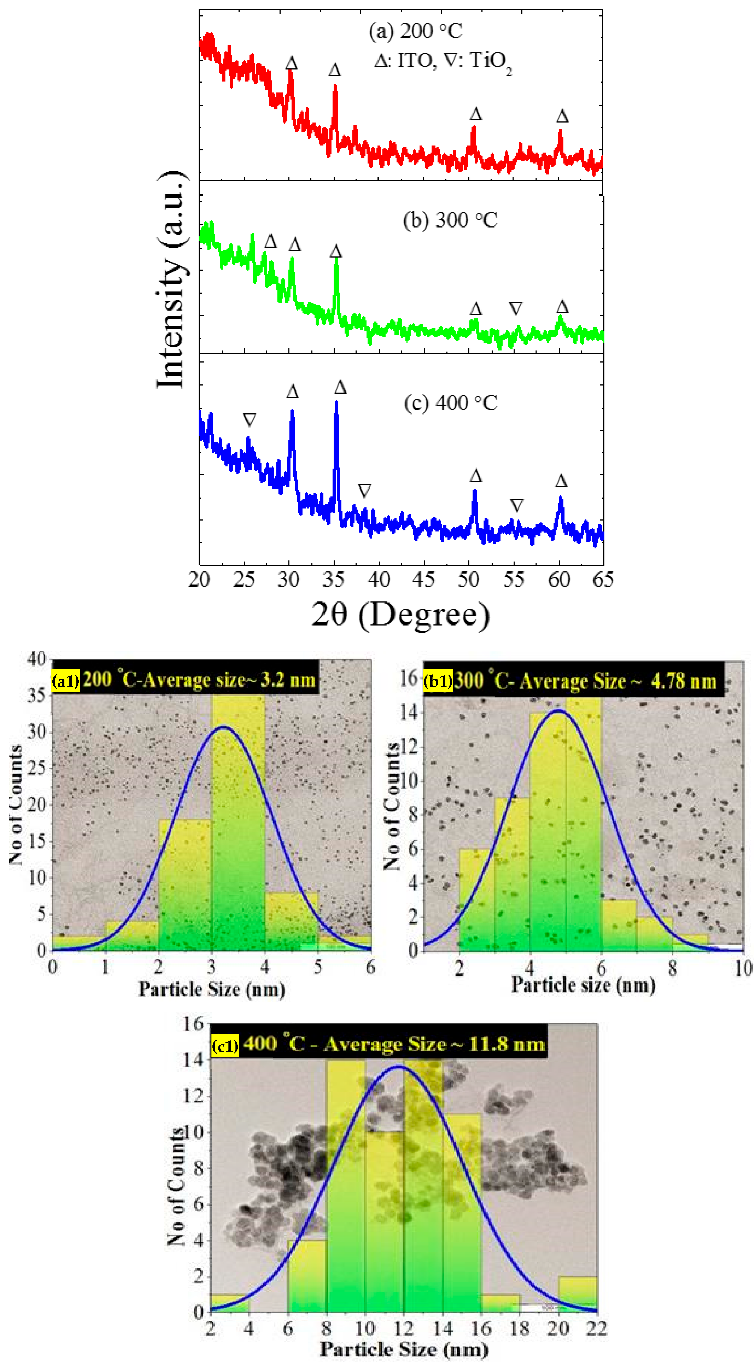
Figure 1 illustrates the cross-sectional FESEM micrograph of the annealed film deposited on ITO glass substrate. The table shows the detected elemental compositions obtained from EDX spectral analyses when scanned at two regions marked as 1 and 2. The main elements in region 1 were Ti and O, which contributed to improving the TiO2NPs yield in the film. The XRD patterns in Figure 2a–c illustrate the effect of various annealing temperatures (200, 300, and 400 °C each for 3 h) on the crystalline structures and phases of the thin film containing TiO2NPs deposited ITO substrate. The XRD profiles consisted of several sharp crystalline peaks corresponding to the ITO in the range of 20–70°. The observed intense peaks at 2θ values of 25.7°, 30.12°, 35.17°, 50°, 57°, and 60.3° corresponded to the crystalline lattice planer directions of the ITO glass substrate. The formation of the main phase of TiO2 as the elementary material was very much sensitive to the annealing temperature and deposition procedure [20]. Figure 2(a1–c1) illustrates the EFTEM micrographs together with their particles size distribution of three TiO2NPs annealed at temperatures of 200, 300, and 400 °C after sonicating the thin film in ethanol to 30 min. The images consisted of spherical-shaped tiny nanocrystallites of average size approximately 3.2, 4.78, and 11.8 nm. The obtained TiO2NPs synthesized at 200 and 300 °C having a size below 5 nm corresponded to the quantum dots structure [21,22]. The ImageJ software program analyzed the micrographs and estimated the average particle size [23].
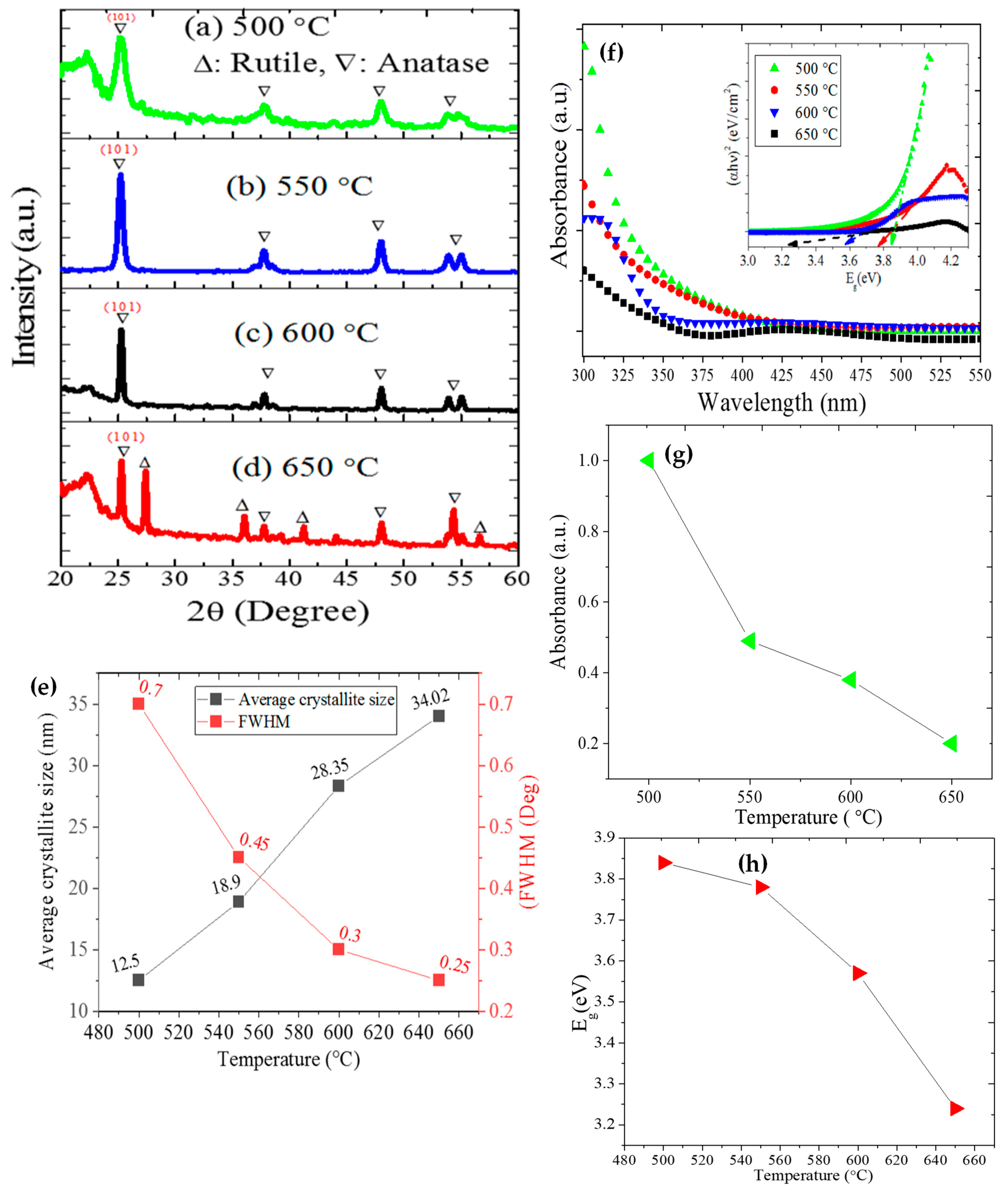
The XRD patterns (in the 2θ range of 20–60°) in Figure 3a–d depicts the influence of various annealing temperatures (500, 550, 600, and 650 °C each for 3 h) on the crystalline structures and phases of the thin film containing TiO2NPs deposited on Si substrate. The XRD profiles of the annealed films displayed many significant Bragg diffraction peaks related to the crystalline anatase and rutile phase of TiO2NPs. In addition, the intensities of these sharp XRD peaks were increased with the increase of annealing temperatures, indicating an improvement in the crystallinity of the films. The main phase of TiO2NPs became anatase with the tetragonal lattice structure at annealing temperature above 400 °C. The film annealed at 650 °C showed the rutile phase formation with the tetragonal structure, due to the sufficient thermal energy-driven (at higher temperature) phase transformation (anatase to rutile) of the TiO2NPs.
The characteristic parameters (value of FWHM (β) and peak position at the Bragg angle (θ)) extracted from the most intense (101) XRD peak of the film obtained at each annealing temperature was utilized to determine the diameter of the TiO2 crystallites ( D ) calculated by Scherrer formula. Figure 3e displays the annealing temperature-dependent variation in the TiO2 crystallite size and FWHM of the intense XRD peak, wherein the crystallite sizes were ranged from 12.15 to 34.02 nm. Furthermore, the TiO2 crystallite sizes were remarkably enlarged with the increase of annealing temperature, suggesting the strong sensitivity of the structure and morphology of the films on the thermal annealing process. The sharpness (high intensity) and broadness (low intensity) of the XRD peaks indicated large crystallite size (strong crystallinity or long-ranged order) and small grain size (weak crystallinity or short-ranged order), respectively. The film annealed at 650 °C showed the formation of the largest TiO2 crystallite [24]. Figure 3f demonstrates the optical absorbance of films containing TiO2NPs deposited on Si substrate and annealed at different temperatures after sonication in ethanol for 30 min. The spectral absorption data of the films were used to generate the Tauc’s plot, and the annealing temperature-dependent modification of the optical bandgap energies was evaluated. Irrespective of the annealing temperature changes, the optical absorbance of the film in the wavelength region of 300 to 400 nm was appreciably increased, indicating the significant structural and morphological modifications due to annealing. In addition, the UV absorption edge of the proposed film enclosing the TiO2NPs showed some notable red-shift (towards longer wavelength) with the increase of annealing temperature, indicating a lowering in the E g . Figure 3g presents the variation in the optical absorbance of the TiO2NPs as a function of annealing temperature. The optical absorbance of TiO2NPs was significantly dropped with the increase of annealing temperature, indicating the strong structural modifications in the electronic energy states. Additionally, TiO2NPs annealed at 500 °C exhibited the highest absorbance. Figure 3h shows the effects of various annealing temperatures on the E g values of the films deposited on Si substrate. The values of E g were remarkably decreased from 3.84 to 3.24 eV, with the increase of annealing temperature. This observation was attributed to the annealing temperature-mediated enlargement in the TiO2 crystallite size, a phenomenon called the quantum de-confinement effect [25,26]. Present results are consistent with the reported values of E g for TiO2 (between 3.2 to 3.8 eV) [27,28].
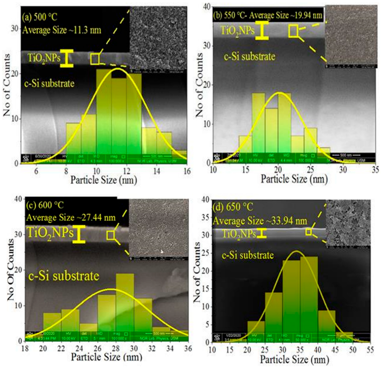
Figure 4 shows the FESEM micrographs (top-view and cross-section view) of the TiO2NPs thin films deposited of Si substrate obtained at different annealing temperatures. Regardless of the annealing temperatures, all the films exhibited spherical-shaped nanocrystallites. In addition, all the films were smooth without any holes or splits, indicating their suitability as a HBL in the HHSCs and QDSCs. The nanocrystallite sizes were increased from 11.3 nm (at 500 °C) to 33.4 nm (at 650 °C), supported by the size estimated via EFTEM and XRD analysis. The observed significant influence of the varying annealing temperatures on the TiO2NPs morphology was consistent with the other findings [29,30,31,32]. Earlier reports argued that the nanocrystallites at the film boundary are weakly attached to their neighbors. Thus, with the increase of annealing temperature, the small crystallites gain enough energy to merge with other crystallites, producing large crystallites in the film.
Figure 5a shows the diffuse reflectance spectrum of the bare c-Si substrate and a thin film containing TiO2NPs annealed at 600 °C. Kubelka–Munk (K-M) function (α) was used to calculate the E g of the film [21,22,33,34] by generating a plot of α × E g n versus E g . The value of E g obtained using K-M function (3.53 eV) was close to the one estimated from Tauc’s method (3.6 eV). The expression of α in terms of the molar absorption coefficient ( K ) and scattering factor ( S ) takes the form = K S , with K = 1 R 2 and S = 2 × R (where R refers to the diffuse reflectance value of film and E g = 1240 λ   eV ). Figure 6b displays the thin film’s FESEM image (top view), which was somewhat uneven with small bumps and zigzag patterns (yellow circle). The observed rapid reduction in the diffuse reflectance of the grown films was mainly due to increased surface roughness [7].
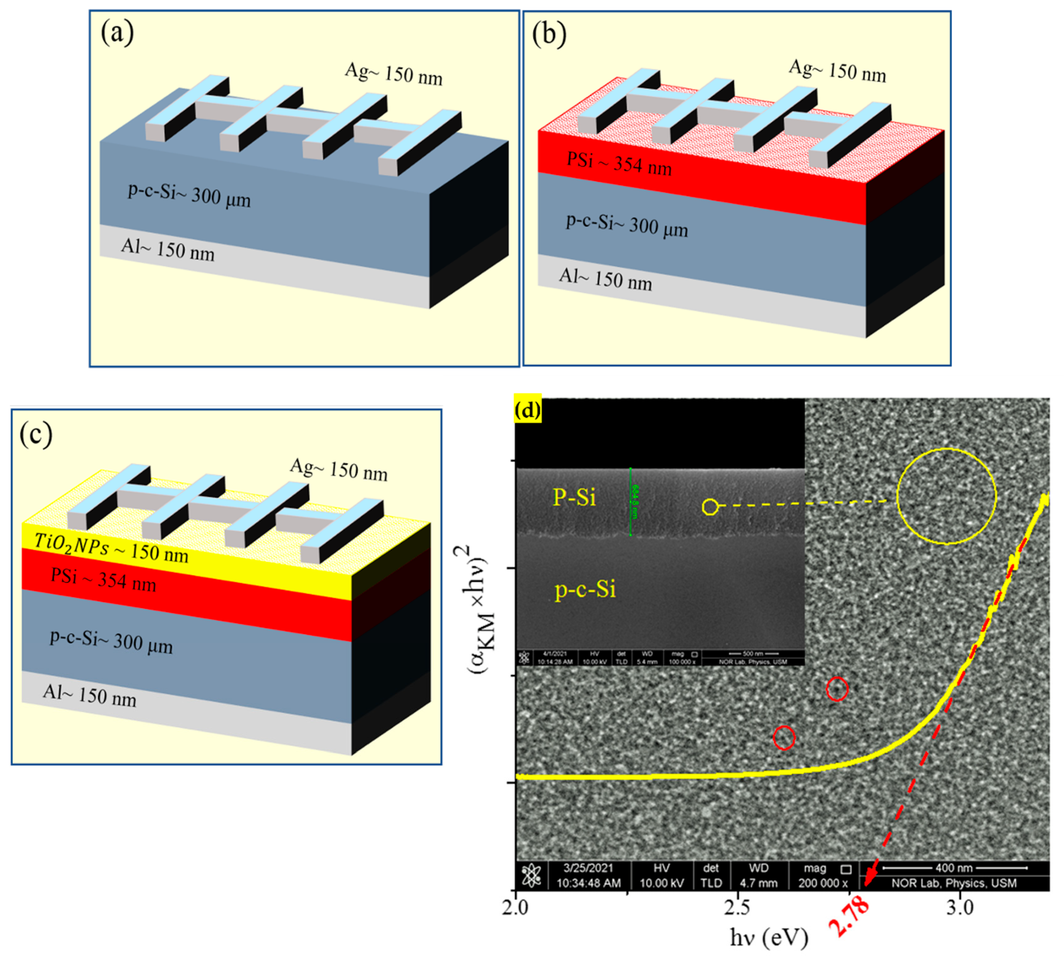
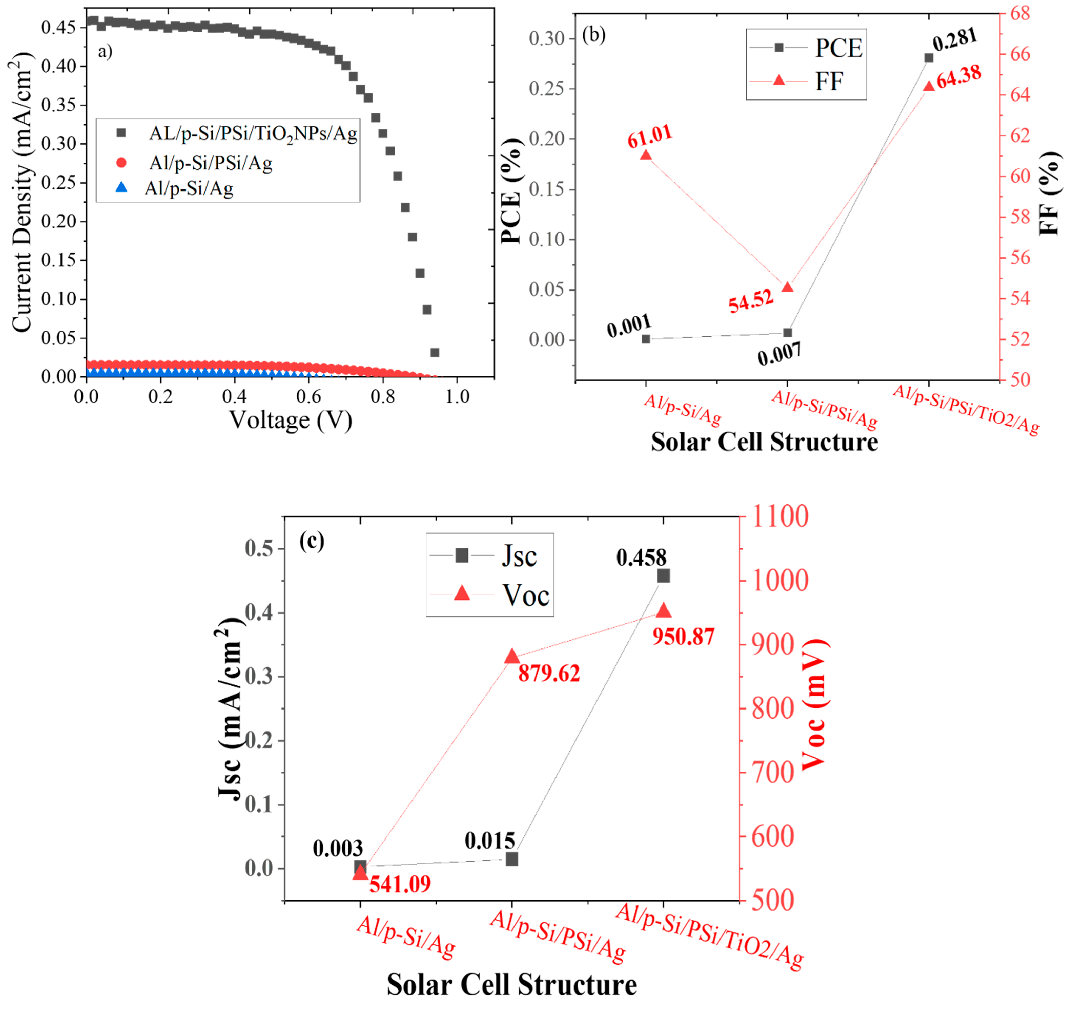
To confirm the photovoltaic potential of the deposited film containing TiO2NPs, an MIS solar cell of the form Al/p-c-Si/PSi/TiO2NPs/Ag was fabricated. Electrical properties, as shown in Figure 6a–c, illustrate the basic architectures of the proposed solar cells of the form Al/p-c-Si/Ag (reference cell), Al/p-c-Si/PSi/Ag (cell with extra PSi layer), and Al/p-c-Si/PSi/TiO2NPs-/Ag (cell with extra thin-film TiO2NPs and PSi layer ), respectively. The Al and Ag layer served as back and forwarded electrodes in these designs. Figure 6d illustrates the cross-sectional FESEM image of P-Si with the corresponding K-M function (inset) used to determine the value of E g . The P-Si layer revealed indirectly to direct band gap energy transition due to the quantum confinement effect, which was due to the shrinkage of Si particle size below 5 nm [35,36]. The value of E g for PSi (~2.78 eV) was comparable with the one obtained previously (2.2 eV) from the photoluminescence spectral analyses [37,38,39]. The solar simulator was used to determine the cell characterization, which gives the value automatically.
Figure 7a–c shows the performance of the three solar cells designed without and with TiO2NPs thin film (annealed at 600 °C). The results clearly showed that the PCE, FF, and I-V characteristics of the photovoltaic cell designed with TiO2NPs thin film were improved compared to those constructed without TiO2NPs. The PCE of the cell with TiO2NPs (0.28%) was much higher compared to the reference cell (0.001%) and the cell with an extra PSi layer (0.007%). The cell’s short circuit current (JSC) with TiO2NPs was almost 153 times and 30 times higher than the reference cell and the PSi layer, respectively. In addition, the open-circuit voltage (VOC) of the cell with TiO2NPs film was almost 1.7 times and 1.1 times higher than the reference cell and the cell with the PSi layer, respectively.
The observed improvement in the performance of the cells fabricated with TiO2NPs film can be explained. The carriers’ recombination rate played a significant role in the PCE enhancement or quenching of the solar cells. It is known that the recombination rate is minimized to improve solar cell performance. The primary sources of the charge carriers on the PSi surface was oxygen defects/vacancies that served as a trap level through the PSi bandgap region. The implementation of TiO2NPs thin film in the cell (size of 27.44 nm) on the top of the PSi layer led to the surface passivation, thereby reducing the oxygen vacancy by covering the surface and infiltrating into the macro-pores (size above 50 nm) of the PSi layer [40]. The micro-pores (size below 2 nm) and mesopores (size range of 2 to 50 nm) [41] were predominant in the PSi layer. However, TiO2NPs with larger dimensions than the mesopores or micro-pores of PSi could prevent their infiltration into those pores.
Crystallization and the crystallite size of samples at 600 °C is more excellent than for samples at 500 °C, and both have anatase phases. The TiO2NPs annealed at 600 °C were deposited on the PSi to passivate the surface. Unfortunately, it cannot penetrate the micropores, so TiO2NPs annealed at 500 °C were used to penetrate in the smallest pores. First, the deposit time for both was the same, and the PCE of the solar cells contained TiO2NPs annealed at 500 °C more than at 600 °C. The deposit time was decreased to reduce the thickness of the film, which will be acted as a tunneling layer. Consequently, it increased the carriers’ recombination rate through the oxygen vacancies and hence the accumulation of the photo-generated carriers (e-h+) was reduced. To improve the solar cell performance, the thickness of the TiO2NPs film was reduced by lowering the deposition time to 0.5 min. The TiO2NPs thin-film acted as a tunneling layer for the electrons at the Ag and PSi interface. Furthermore, the mean size of TiO2NPs in the film annealed at 500 °C was 11.3 nm, chosen to coat the PSi layer as optimum ETL to get the highest photovoltaic performance in terms of PCE and FF.
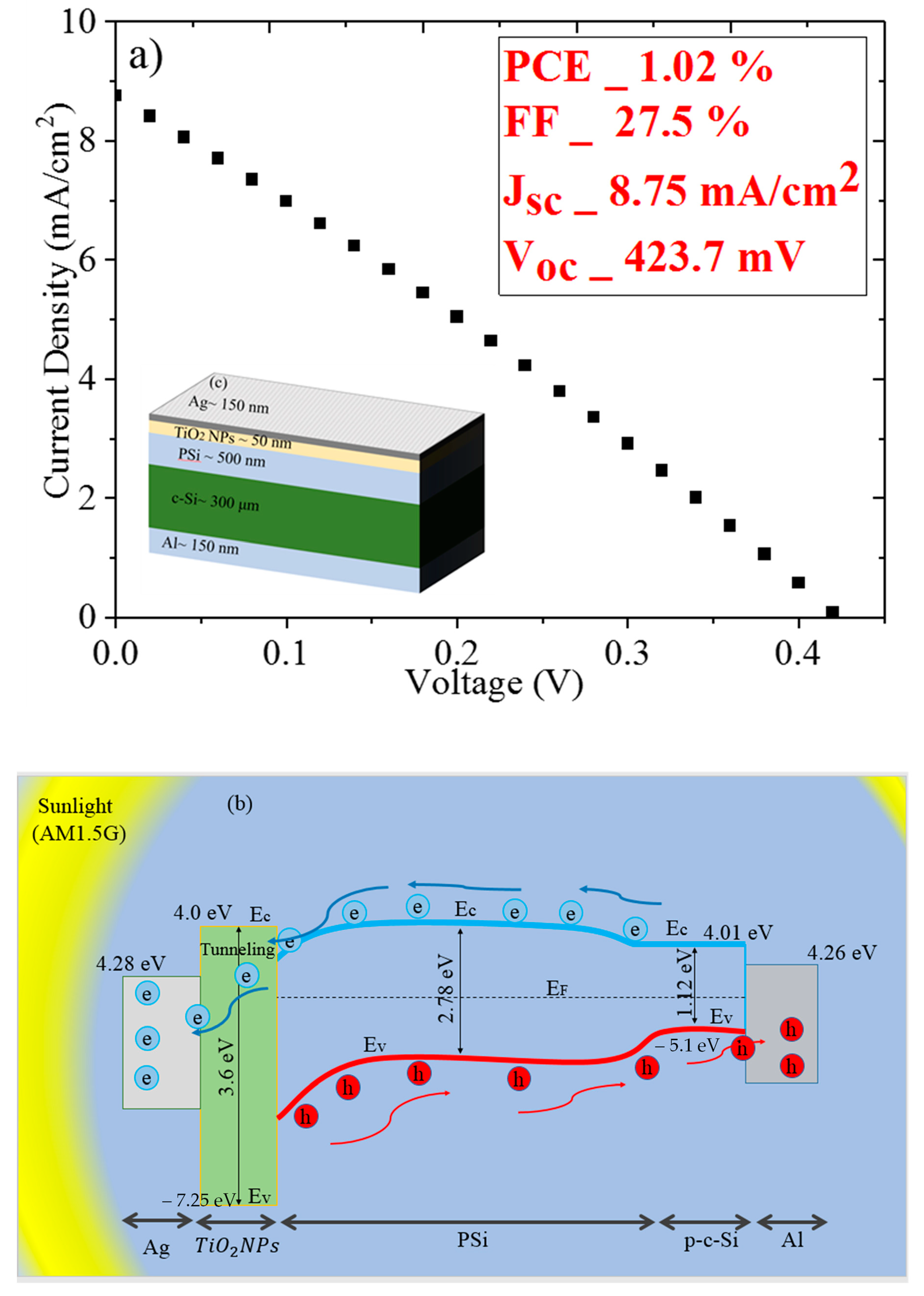
Figure 8a shows the photovoltaic performance of the proposed cells (in terms of terms I-V characteristics, cell configuration together with PCE, FF, JSC, and VOC under sunlight exposure, AM1.5G) fabricated using annealed (500 °C) TiO2NPs film. The value of PCE (1.02%) and Jsc (8.75 mA/cm2) of the thermally annealed TiO2NPs film incorporated solar cell was much higher compared to the film annealed at 600 °C (PCE of 0.28% and Jsc of 0.458 mA/cm2). In addition, the PCE was enhanced by 3.6 times and Jsc by 19 times compared to the film annealed at 600 °C. Conversely, the values of VOC and FF were reduced due to the more isolation of the TiO2NPs originated from the increased bandgap energy of the film [42,43].
Figure 8b displays the energy band diagram of the ETL-based cell, indicating the mechanism of electrons tunneling, carriers’ generation, and recombination across the energy bandgap. The carrier’s concentration in the p-c-Si and PSi layer calculated using the theory of Hall effect was ~ 3 × 10 16   cm 3 and 3 × 10 11   cm 3 , respectively. This indicated that PSi behaved as an intrinsic semiconductor with the Fermi level located at the centre of the bandgap [44,45]. The conduction band energy for Si and TiO2 being 4.01 and 4.02 eV, respectively [46], the energy difference (ΔEc) between the conduction states of Si and TiO2 were too small, enabling the extraction of the photo-generated electrons in the ETL. In contrast, the valance band energy for Si and TiO2 was 5.1 and 7.25 eV. The energy difference ( Δ Ev ~ 2.15   eV ) between the valence states of Si and TiO2 were too large, preventing the holes extraction at Si-TiO2 interface and thus acted as HBL [47]. In addition, work functions (Φ) of Ag (4.28 eV) and Al (4.26 eV) facilitated the rapid acceptance of the carriers towards the electrodes [6,48,49]. On top, the values of Ec, Ev, and Φ of the materials in the proposed solar cell were fluctuated, slightly depending on the method of thin films deposition [50]. Table 1 compares the performance of the proposed cell with the other state-of-the-art works reported in the literature. In short, the proposed solar cell was fabricated using the thermally annealed TiO2NPs film outperformed the existing cells reported in the literature.
The current density improvement was related to the extraction of the photo-generated carriers. If the electron in the valance band absorbed enough energy, it would transfer to a conduction band, which was left behind a hole in the valance band. These e-h pairs possess two choices, (1) recombination and which leads to generating electromagnetic waves (photoluminescence), (2) extraction of the electron and hole, which were improved the current density. In this experiment, the current density increased from 0.458 mA/cm2 to 8.75 mA/cm2, meaning the JSC was enhanced by 19 times. This improvement in the current density refers to increasing the electrons and holes extraction or reducing the recombination process.

4. Conclusions

Thin films TiO2NPs were prepared via the pyrolysis process on ITO glass and Si substrate. The obtained thin films were annealed at various temperatures (200 to 650 °C) to achieve the optimum ETL for the solar cell fabrication. The variation of annealing temperature was shown to play a significant role in the film’s structures and absorbance properties beneficial for the ETL design in the solar cells. The MIS-SC was constructed with the thermally annealed TiO2NPs film as ETL excellent photovoltaic performance with the corresponding PCE and JSC values of 1.02 and 8.75 mA/cm2. The sizes of TiO2NPs and the thickness of the film strongly influenced the cell’s performance.

Supplementary Materials

The following are available online at https://www.mdpi.com/article/10.3390/en15051648/s1, Figure S1: (a) Flowchart of the TiO2NPs procedure, (b)TiO2 thin films deposition procedure.

Author Contributions

Conceptualization, N.M.A., M.R., M.S.A. and M.A.A.; Methodology, N.M.A. and M.R.; Software, M.S.A. and N.M.A.; Validation, N.M., O.A.A. and K.H.I.; Formal analysis, M.S.A.; Investigation, M.S.A.; Resources, N.M.A., M.S.A., N.S., M.A.A. and N.M.; Data curation, M.S.A., O.A.A. and K.H.I.; Writing—original draft preparation, M.S.A. and N.M.A.; Writing—review and editing, M.S.A., N.M., K.H.I. and O.A.A.; Visualization, N.M.A. and M.R.; Supervision, N.M.A. and M.R.; Project administration, N.M.A., O.A.A. and K.H.I.; Funding acquisition, N.M. and O.A.A. All authors have read and agreed to the published version of the manuscript.

Funding

The authors extend their appreciation to the Deanship of Scientific Research at Imam Mohammad Ibn Saud Islamic University for funding this work through Research Group no. RG-21-09-53.

Acknowledgments

The authors are thankful to the Deanship of Scientific Research at Imam Mohammad Ibn Saud Islamic University for funding this work. The authors extend their appreciation to the School of Physics, Universiti Sains Malaysia for the facilities and the technical support. The authors gratefully acknowledge Ahmed Alsadig (University of Trieste) for his kind assistance throughout this work.

Conflicts of Interest

The authors declare no conflict of interest.

References

  1. He, Y.; Sutton, N.B.; Rijnaarts, H.; Langenhoff, A. Degradation of pharmaceuticals in wastewater using immobilized TiO2 photocatalysis under simulated solar irradiation. Appl. Catal. B Environ. 2016, 182, 132–141. [Google Scholar] [CrossRef]
  2. Zatloukalová, K.; Obalová, L.; Koči, K.; Čapek, L.; Matěj, Z.; Šnajdhaufová, H.; Ryczkowski, J.; Słowik, G. Photocatalytic degradation of endocrine disruptor compounds in water over immobilized TiO2 photocatalysts. Iran. J. Chem. Chem. Eng. 2017, 36, 29–38. [Google Scholar]
  3. Dai, Y.; Cobley, C.M.; Zeng, J.; Sun, Y.; Xia, Y. Synthesis of anatase TiO2 nanocrystals with exposed {001} facets. Nano Lett. 2009, 9, 2455–2459. [Google Scholar] [CrossRef] [PubMed]
  4. Park, S.-W.; Jang, J.-T.; Cheon, J.; Lee, H.-H.; Lee, D.R.; Lee, Y. Shape-Dependent Compressibility of TiO2 Anatase Nanoparticles. J. Phys. Chem. C 2008, 112, 9627–9631. [Google Scholar] [CrossRef]
  5. Cozzoli, P.D.; Kornowski, A.A.; Weller, H. Low-Temperature Synthesis of Soluble and Processable Organic-Capped Anatase TiO2 Nanorods. J. Am. Chem. Soc. 2003, 125, 14539–14548. [Google Scholar] [CrossRef]
  6. Elsaeedy, H.; Qasem, A.; Yakout, H.; Mahmoud, M. The pivotal role of TiO2 layer thickness in optimizing the performance of TiO2/P-Si solar cell. J. Alloys Compd. 2021, 867, 159150. [Google Scholar] [CrossRef]
  7. Saint-André, S.; Rodríguez, D.; Perillo, P.; Barrera, M. TiO2 nanotubes antireflection coating design for GaAs solar cells. Sol. Energy Mater. Sol. Cells 2021, 230, 111201. [Google Scholar] [CrossRef]
  8. Lv, Y.; Tong, H.; Cai, W.; Zhang, Z.; Chen, H.; Zhou, X. Boosting the efficiency of commercial available carbon-based perovskite solar cells using Zinc-doped TiO2 nanorod arrays as electron transport layer. J. Alloys Compd. 2021, 851, 156785. [Google Scholar] [CrossRef]
  9. Ojo, A.A.; Cranton, W.M.; Dharmadasa, I.M. Photovoltaic Solar Cells: Materials, Concepts and Devices. In Next Generation Multilayer Graded Bandgap Solar Cells; Springer Science and Business Media LLC: Berlin, Germany, 2018; pp. 17–40. [Google Scholar]
  10. Dharmadasa, I.M.; Thornton, J.M.; Williams, R.H. Effects of surface treatments on Schottky barrier formation at metal/n-type CdTe contacts. Appl. Phys. Lett. 1989, 54, 137–139. [Google Scholar] [CrossRef]
  11. Godfrey, R.B.; Green, M.A. Enhancement of MIS solar-cell’’efficiency’’by peripheral collection. Appl. Phys. Lett. 1977, 31, 705–707. [Google Scholar] [CrossRef]
  12. Nevin, W.; Chamberlain, G. Effect of oxide thickness on the properties of metal-insulator-organic semiconductor photovoltaic cells. IEEE Trans. Electron Devices 1993, 40, 75–81. [Google Scholar] [CrossRef]
  13. Sze, S.M.; Ng, K.K. Physics of Semiconductor Devices, 3rd ed.; John Wiley and Sons: Hoboken, NJ, USA, 2007. [Google Scholar]
  14. Kim, J.M.; Kim, S.; Shin, D.H.; Seo, S.W.; Lee, H.S.; Kim, J.H.; Jang, C.W.; Kang, S.S.; Choi, S.-H.; Kwak, G.Y.; et al. Si-quantum-dot heterojunction solar cells with 16.2% efficiency achieved by employing doped-graphene transparent conductive electrodes. Nano Energy 2018, 43, 124–129. [Google Scholar] [CrossRef]
  15. Sasirekha, N.; Rajesh, B.; Chen, Y.-W. Synthesis of TiO2 sol in a neutral solution using TiCl4 as a precursor and H2O2 as an oxidizing agent. Thin Solid Film. 2009, 518, 43–48. [Google Scholar] [CrossRef]
  16. Lee, D.-S.; Liu, T.-K. Preparation of TiO2 Sol Using TiCl4 as a Precursor. J. Sol-Gel Sci. Technol. 2002, 25, 121–136. [Google Scholar] [CrossRef]
  17. Al-Diabat, A.M.; Ahmed, N.M.; Hashim, M.R.; Chahrour, K. Influence of the spray distance to substrate on optical properties of chemically sprayed ZnS thin films. J. Mater. Sci. Mater. Electron. 2017, 28, 371–375. [Google Scholar] [CrossRef]
  18. Eze, M.C.; Ugwuanyi, G.; Li, M.; Eze, H.U.; Rodriguez, G.M.; Evans, A.; Rocha, V.G.; Li, Z.; Min, G. Optimum silver contact sputtering parameters for efficient perovskite solar cell fabrication. Sol. Energy Mater. Sol. Cells 2021, 230, 111185. [Google Scholar] [CrossRef]
  19. Balaji, P.; Dauksher, W.J.; Bowden, S.G.; Augusto, A. Improving surface passivation on very thin substrates for high efficiency silicon heterojunction solar cells. Sol. Energy Mater. Sol. Cells 2020, 216, 110715. [Google Scholar] [CrossRef]
  20. Mechiakh, R.; Ben Sedrine, N.; Ben Naceur, J.; Chtourou, R. Elaboration and characterization of nanocrystalline TiO2 thin films prepared by sol–gel dip-coating. Surf. Coat. Technol. 2011, 206, 243–249. [Google Scholar] [CrossRef]
  21. Šutka, A.; Eglitis, R.; Kuzma, A.; Smits, K.; Zukuls, A.; Prades, J.D.; Fàbrega, C. Photodoping-Inspired Room-Temperature Gas Sensing by Anatase TiO2 Quantum Dots. ACS Appl. Nano Mater. 2021, 4, 2522–2527. [Google Scholar] [CrossRef]
  22. Gnanasekaran, L.; Hemamalini, R.; Ravichandran, K. Synthesis and characterization of TiO2 quantum dots for photocatalytic application. J. Saudi Chem. Soc. 2015, 19, 589–594. [Google Scholar] [CrossRef] [Green Version]
  23. Nomaan, A.T.; Ahmed, A.A.; Ahmed, N.M.; Idris, M.; Hashim, M.; Rashid, M. ZnO quantum dot based thin films as promising electron transport layer: Influence of surface-to-volume ratio on the photoelectric properties. Ceram. Int. 2021, 47, 12397–12409. [Google Scholar] [CrossRef]
  24. Bakri, A.S.; Sahdan, M.Z.; Adriyanto, F.; Raship, N.A.; Said, N.D.M.; Abdullah, S.A.; Rahim, M.S. Effect of annealing temperature of titanium dioxide thin films on structural and electrical properties. In AIP Conference Proceedings; AIP Publishing LLC: Melville, NY, USA, 2017; Volume 1788, p. 030030. [Google Scholar] [CrossRef] [Green Version]
  25. Viseu, T.M.; Ferreira, M.C. Morphological characterization of TiO2 thin films. Vacuum 1999, 52, 115–120. [Google Scholar] [CrossRef]
  26. Manickam, K.; Muthusamy, V.; Manickam, S.; Senthil, T.S.; Periyasamy, G.; Shanmugam, S. Effect of annealing temperature on structural, morphological and optical properties of nanocrystalline TiO2 thin films synthesized by sol–gel dip coating method. Mater. Today Proc. 2020, 23, 68–72. [Google Scholar]
  27. Nandani; Supriyanto, A.; Ramelan, A.H.; Nurosyid, F. Effect of annealing temperature on optical properties of TiO2 18 NR-T type thin film. J. Phys. Conf. Ser. 2018, 1011, 012016. [Google Scholar] [CrossRef]
  28. Grätzel, M. Dye-sensitized solar cells. J. Photochem. Photobiol. C Photochem. Rev. 2003, 4, 145–153. [Google Scholar]
  29. Kheiri, F.; Soleimanian, V.; Ghasemi, M.; Mokhtari, A. The microstructure, optical and gas sensing properties of bilayer TiO2/ZnO systems in terms of annealing temperature. Mater. Sci. Semicond. Process. 2021, 121, 105462. [Google Scholar]
  30. Munguti, L.; Dejene, F. Influence of annealing temperature on structural, optical and photocatalytic properties of ZnO–TiO2 composites for application in dye removal in water. Nano-Struct. Nano-Objects 2020, 24, 100594. [Google Scholar] [CrossRef]
  31. Timoumi, A.; Albetran, H.M.; Alamri, H.R.; Alamri, S.N.; Low, I.M. Impact of annealing temperature on structural, morphological and optical properties of GO-TiO2 thin films prepared by spin coating technique. Superlattices Microstruct. 2020, 139, 106423. [Google Scholar]
  32. He, Y.; Yan, Q.; Liu, X.; Dong, M.; Yang, J. Effect of annealing on the structure, morphology and photocatalytic activity of surface-fluorinated TiO2 with dominant {001} facets. J. Photochem. Photobiol. A Chem. 2020, 393, 112400. [Google Scholar]
  33. Quintero, Y.; Mosquera, E.; Diosa, J.; García, A. Ultrasonic-assisted sol–gel synthesis of TiO2 nanostructures: Influence of synthesis parameters on morphology, crystallinity, and photocatalytic performance. J. Sol-Gel Sci. Technol. 2020, 94, 477–485. [Google Scholar] [CrossRef]
  34. Kubelka, P. New contributions to the optics of intensely light-scattering materials. Part I. Josa 1948, 38, 448–457. [Google Scholar] [CrossRef] [PubMed]
  35. López-rojas, O.; Guzmán, J.G. A review on quantum dot solar cells: Properties, materials, synthesis and devices. In Proceedings of the 2019 IEEE International Conference on Engineering Veracruz (ICEV), Boca del Rio, Mexico, 14–17 October 2019; Volume 1, pp. 1–5. [Google Scholar]
  36. Herbert, F.; Krishnamoorthy, A.; Van Vliet, K.; Yildiz, B. Quantification of electronic band gap and surface states on FeS2(100). Surf. Sci. 2013, 618, 53–61. [Google Scholar] [CrossRef]
  37. Almomani, M.S.; Ahmed, N.M.; Rashid, M.; Almessiere, M.; Altowyan, A.S. Broadband visible emission from photoelectrochemical etched porous silicon quantum dots containing zinc. Mater. Chem. Phys. 2021, 258, 123935. [Google Scholar] [CrossRef]
  38. Almomani, M.S.; Ahmed, N.M.; Rashid, M.; Almessiere, M.A.; Altowyan, A.S. White, blue and green emission from Si QDs derived from zinc incorporated porous silicon. J. Lumin. 2021, 232, 117845. [Google Scholar] [CrossRef]
  39. Almomani, M.S.; Ahmed, N.M.; Rashid, M.; Ali, M.K.M.; Akhdar, H.; Aldaghri, O.; Ibnaouf, K.H. Enhancement of Temperature Fluorescence Brightness of Zn@Si Core-Shell Quantum Dots Produced via a Unified Strategy. Nanomaterials 2021, 11, 3158. [Google Scholar] [CrossRef]
  40. Iatsunskyi, I.; Pavlenko, M.; Viter, R.; Jancelewicz, M.; Nowaczyk, G.; Baleviciute, I.; Załęski, K.; Jurga, S.; Ramanavicius, A.; Smyntyna, V. Tailoring the Structural, Optical, and Photoluminescence Properties of Porous Silicon/TiO2 Nanostructures. J. Phys. Chem. C 2015, 119, 7164–7171. [Google Scholar] [CrossRef]
  41. Hao, Y.; Kang, Y.; Mi, Y.; Wang, W.; Lei, Z. Highly ordered micro-meso-macroporous Co-N-doped carbon polyhedrons from bimetal-organic frameworks for rechargeable Zn-air batteries. J. Colloid Interface Sci. 2021, 598, 83–92. [Google Scholar] [CrossRef]
  42. Kaulgud, S.; Sharma, R.; Jolly, L.; Mishra, B.K. Enhanced surface passivation with TIPS pentacene and additional interfacial layer for MIS solar cells. Int. J. Inf. Technol. 2021, 13, 1323–1330. [Google Scholar] [CrossRef]
  43. Ramadan, R.; Manso-silva, M. Composites Hybrid porous silicon / silver nanostructures for the development of enhanced photovoltaic devices. J. Mater. Sci. 2020, 55, 5458–5470. [Google Scholar] [CrossRef]
  44. Shin, D.H.; Kim, J.H.; Kim, J.H.; Jang, C.W.; Seo, S.W.; Lee, H.S.; Kim, S.; Choi, S.-H. Graphene/porous silicon Schottky-junction solar cells. J. Alloys Compd. 2017, 715, 291–296. [Google Scholar] [CrossRef]
  45. Gallach-Pérez, D.; Muñoz-Noval, A.; García-Pelayo, L.; Manso-Silván, M.; Torres-Costa, V. Tunnel conduction regimes, white-light emission and band diagram of porous silicon–zinc oxide nanocomposites. J. Lumin. 2017, 191, 107–111. [Google Scholar] [CrossRef]
  46. Zha, R.; Nadimicherla, R.; Guo, X. Ultraviolet photocatalytic degradation of methyl orange by nanostructured TiO2/ZnO heterojunctions. J. Mater. Chem. A 2015, 3, 6565–6574. [Google Scholar] [CrossRef]
  47. Deb, P.; Dhar, J.C. Graphene oxide charge blocking layer with high K TiO2 nanowire for improved capacitive memory. J. Alloys Compd. 2021, 868, 159095. [Google Scholar] [CrossRef]
  48. Choudhury, B.D.; Lin, C.; Shawon, S.M.A.Z.; Soliz-Martinez, J.; Huq, H.; Uddin, M.J. A photoanode with hierarchical nanoforest TiO2 structure and silver plasmonic nanoparticles for flexible dye sensitized solar cell. Sci. Rep. 2021, 11, 7552. [Google Scholar] [CrossRef] [PubMed]
  49. Kanjana, N.; Maiaugree, W.; Poolcharuansin, P.; Laokul, P. Synthesis and characterization of Fe-doped TiO2 hollow spheres for dye-sensitized solar cell applications. Mater. Sci. Eng. B 2021, 271, 115311. [Google Scholar] [CrossRef]
  50. Mansfeldova, V.; Zlamalova, M.; Tarabkova, H.; Janda, P.; Vorokhta, M.; Piliai, L.; Kavan, L. Work Function of TiO2 (Anatase, Rutile, and Brookite) Single Crystals: Effects of the Environment. J. Phys. Chem. C 2021, 125, 1902–1912. [Google Scholar] [CrossRef]
  51. Lin, Y.-K.; Hong, Y.-T.; Shyue, J.-J.; Hsueh, C.-H. Construction of Schottky junction solar cell using silicon nanowires and multi-layered graphene. Superlattices Microstruct. 2019, 126, 42–48. [Google Scholar] [CrossRef]
  52. Gnisci, A.; Faggio, G.; Lancellotti, L.; Messina, G.; Carotenuto, R.; Bobeico, E.; Veneri, P.D.; Capasso, A.; Dikonimos, T.; Lisi, N. The Role of Graphene-Based Derivative as Interfacial Layer in Graphene/n-Si Schottky Barrier Solar Cells. Phys. Status Solidi 2018, 216, 1800555. [Google Scholar] [CrossRef]
  53. Yi, Z.; Zeng, Y.; Wu, H.; Chen, X.; Fan, Y.; Yang, H.; Tang, Y.; Yi, Y.; Wang, J.; Wu, P. Synthesis, surface properties, crystal structure and dye-sensitized solar cell performance of TiO2 nanotube arrays anodized under different parameters. Results Phys. 2019, 15, 102609. [Google Scholar] [CrossRef]
  54. Tong, C.; Yun, J.; Song, H.; Gan, Q.; Anderson, W.A. Plasmonic-enhanced Si Schottky barrier solar cells. Sol. Energy Mater. Sol. Cells 2014, 120, 591–595. [Google Scholar] [CrossRef]
  55. Solaiyammal, T.; Murugakoothan, P. Green synthesis of Au and the impact of Au on the efficiency of TiO2 based dye sensitized solar cell. Mater. Sci. Energy Technol. 2019, 2, 171–180. [Google Scholar] [CrossRef]
  56. Ramakrishnan, V.M.; Muthukumarasamy, N.; Balraju, P.; Pitchaiya, S.; Velauthapillai, D.; Pugazhendhi, A. Transformation of TiO2 nanoparticles to nanotubes by simple solvothermal route and its performance as dye-sensitized solar cell (DSSC) photoanode. Int. J. Hydrogen Energy 2020, 45, 15441–15452. [Google Scholar] [CrossRef]
  57. Chong, S.W.; Lai, C.W.; Juan, J.C.; Leo, B.F. An investigation on surface modified TiO2 incorporated with graphene oxide for dye-sensitized solar cell. Sol. Energy 2019, 191, 663–671. [Google Scholar] [CrossRef]
  58. Neetu; Singh, S.; Srivastava, P.; Bahadur, L. Hydrothermal synthesized Nd-doped TiO2 with Anatase and Brookite phases as highly improved photoanode for dye-sensitized solar cell. Sol. Energy 2020, 208, 173–181. [Google Scholar] [CrossRef]
  59. Kathirvel, S.; Pedaballi, S.; Su, C.; Chen, B.-R.; Li, W.-R. Morphological control of TiO2 nanocrystals by solvothermal synthesis for dye-sensitized solar cell applications. Appl. Surf. Sci. 2020, 519, 146082. [Google Scholar] [CrossRef]
  60. Teimouri, R.; Heydari, Z.; Ghaziani, M.P.; Madani, M.; Abdy, H.; Kolahdouz, M.; Asl-Soleimani, E. Synthesizing Li doped TiO2 electron transport layers for highly efficient planar perovskite solar cell. Superlattices Microstruct. 2020, 145, 106627. [Google Scholar] [CrossRef]
  61. Wang, L.; Chen, K.; Tong, H.; Wang, K.; Tao, L.; Zhang, Y.; Zhou, X. Inverted pyramid Er3+ and Yb3+ Co-doped TiO2 nanorod arrays based perovskite solar cell: Infrared response and improved current density. Ceram. Int. 2020, 46, 12073–12079. [Google Scholar] [CrossRef]
  62. Kim, M.; Choi, I.-W.; Choi, S.J.; Song, J.W.; Mo, S.-I.; An, J.-H.; Jo, Y.; Ahn, S.; Ahn, S.K.; Kim, G.-H.; et al. Enhanced electrical properties of Li-salts doped mesoporous TiO2 in perovskite solar cells. Joule 2021, 5, 659–672. [Google Scholar] [CrossRef]
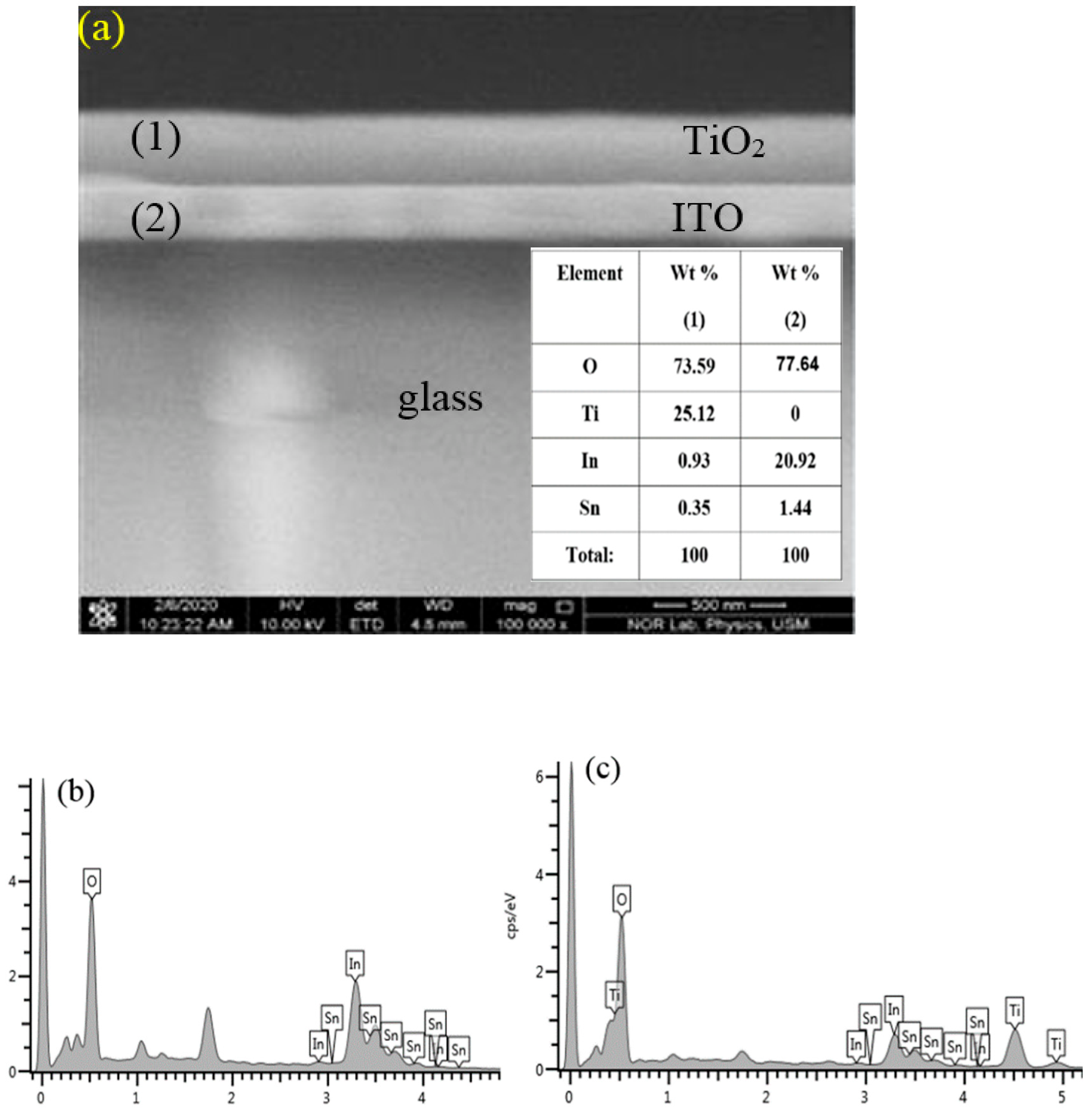
Figure 1. (a) FESEM image deposited on ITO glass substrate and (b,c) the corresponding EDX elemental traces.
Energies 15 01648 g001
Figure 2. XRD patterns of the thin film deposited on ITO substrate after annealing at temperatures (a) 200, (b) 300, and (c) 400 °C. EFTEM morphology of the thin films annealed at (a1) 200, (b1) 300, and (c1) 400 °C.
Energies 15 01648 g002
Figure 3. XRD patterns of the thin film deposited on Si substrate after annealing at temperature (a) 500, (b) 550, (c) 600, and (d) 650 °C. (e) Annealing temperature-dependent variation in the crystallite size and FWHM of the studied films. (f,g) The optical absorbance of the thin films annealed at different temperatures. (h) Effect of annealing temperature on the E g .
Energies 15 01648 g003
Figure 4. FESEM images top-view together with corresponding particles size distribution and cross-section view (inset) of the films deposited on Si substrate and annealed at temperatures (a) 500, (b) 550, (c) 600, and (d) 650 °C.
Energies 15 01648 g004
Figure 5. (a) Diffuse reflectance spectrum of c-Si substrate and thin-film annealed at 600 °C and (b) FESEM image (top view) of the same film deposited on c-Si and annealed at 600 °C.
Energies 15 01648 g005
Figure 6. (ac) Architectures of the proposed solar cells obtained using TiO2NPs-enclosed thin film as ETL. (d) Cross-sectional view and top view of the FESEM image for P-Si together with the K-M plot indicating the band gap energy.
Energies 15 01648 g006
Figure 7. Photovoltaic performance of the proposed cells fabricated without and with TiO2NPs (a) I-V characteristics (b) PCE and FF, (c) JSC and VOC.
Energies 15 01648 g007
Figure 8. Photovoltaic performance of the proposed cells (under sunlight exposure) fabricated with annealed (500 °C) TiO2NPs film (a) I-V characteristics, cell configuration together with PCE, FF, JSC, and VOC, and (b) energy band diagram showing the mechanism of electrons tunneling, carriers’ generation across the energy bandgap.
Energies 15 01648 g008
Table 1. Comparative evaluation of the performance of the proposed cell with other state-of-the-art works reported in the literature.
Solar Cell StructureImprovement byEnhancement η (%)Ref.
Glass/Cu/n-Si/Si NW + G/SiO2/AgSi NW + G100[51]
FLG/2GBD/n-Si2GBD56.2[52]
DSSC719dye + TiO2 nanotube87.5[53]
Al/p-c-Si/SiO2/Cr/Au/AgAg nanoparticle + SiO280.4[54]
Al/p-c-Si/P-Si + Ag/TiO2/AuP-Si + Ag111.2[43]
Au:TiO2 based DSSCAu/TiO265.1[55]
TiO2 nanotube based DSSCTiO2 nanotube53.6[56]
GO-TiO2 based DSSCGO-TiO2126.4[57]
Nd-TiO2 based DSSCNd-TiO234.3[58]
DSSCTiO250.5[59]
FTO/Li-TiO2/perovskite/Spiro-OMeTAD/AuLi-TiO21.97[60]
FTO/TiO2:Yb3+,Er3+/perovskite/Spiro-OMeTAD/AgTiO2: Yb3+, Er3+16.5[61]
FTO/cTiO2/mpTiO2/perovskite/Spiro-OMeTAD/AgmpTiO29.2[62]
Al/p-c-Si/PSi/TiO2NPs/AgPSi264.3Present
Publisher’s Note: MDPI stays neutral with regard to jurisdictional claims in published maps and institutional affiliations.