
Analyzing Europe’s Biggest Offshore Wind Farms: A Data Set with 40 Years of Hourly Wind Speeds and Electricity Production


Abstract
:1. Introduction
2. Data
3. Analysis
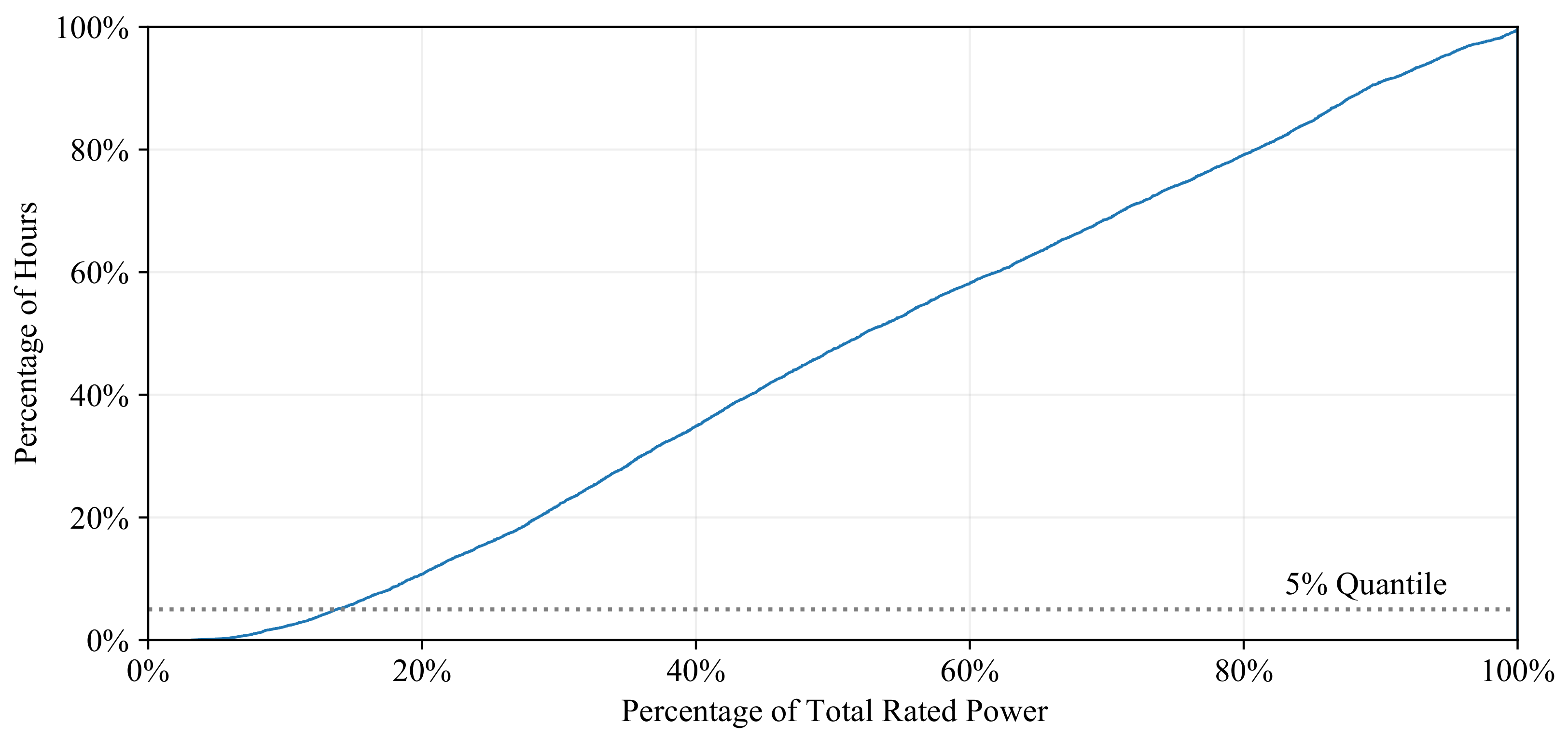
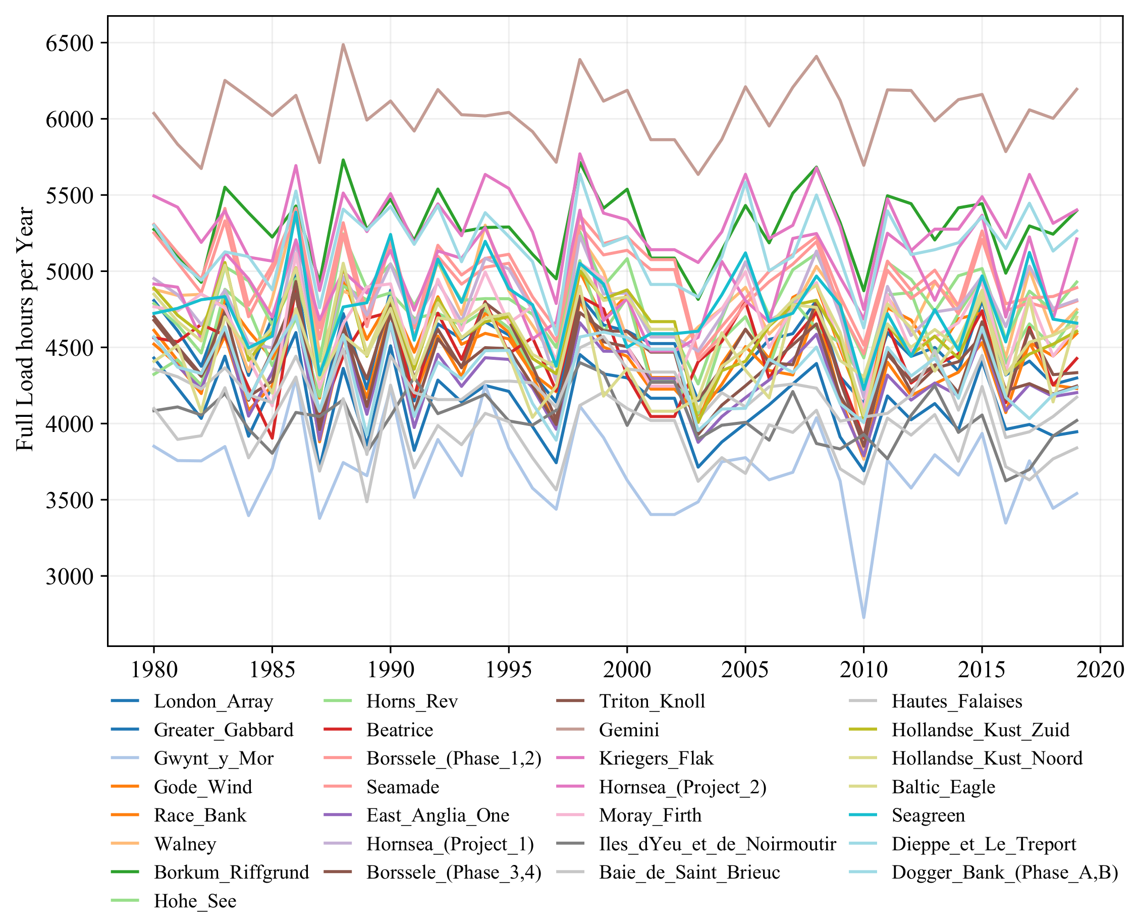
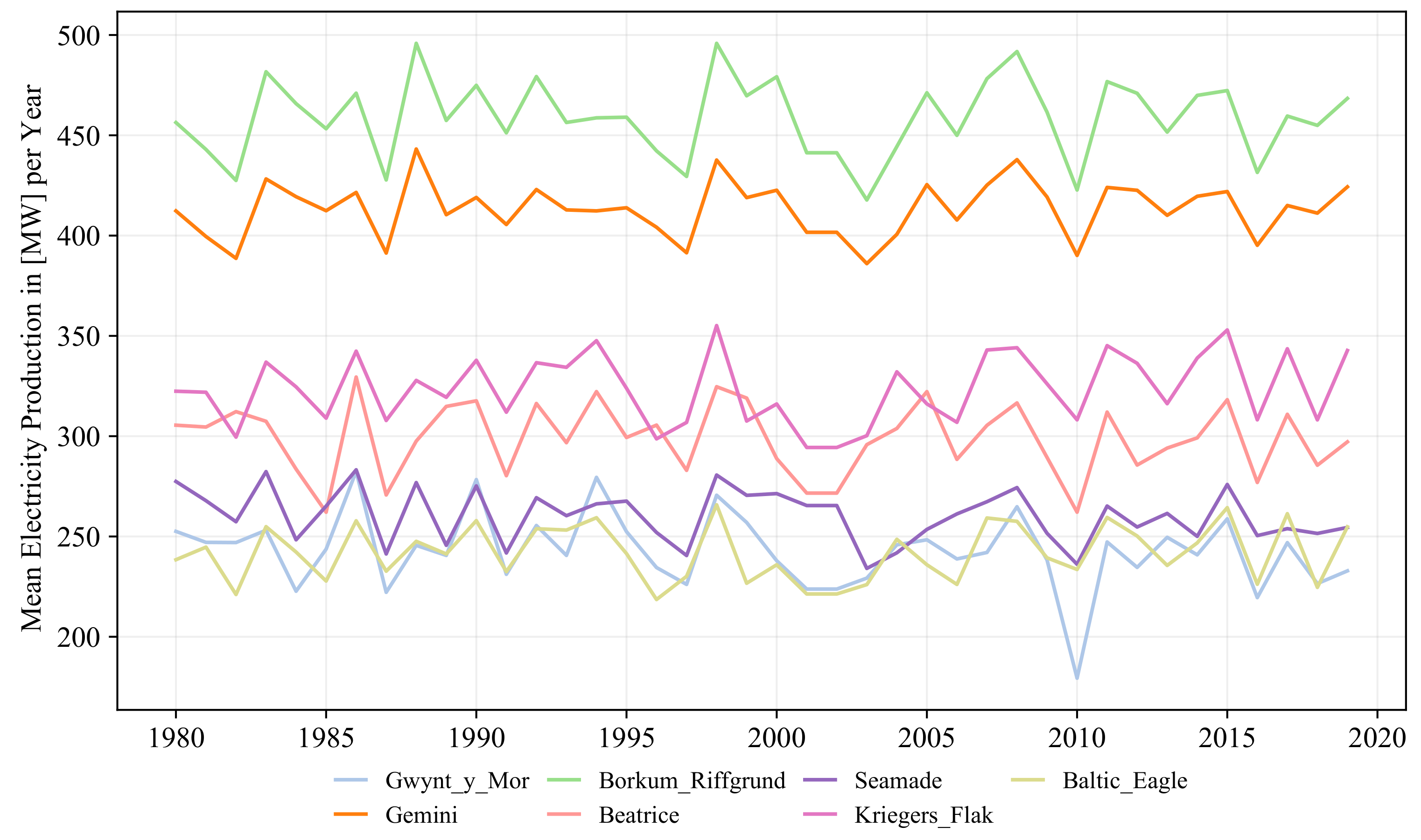
3.1. Descriptive Statistics
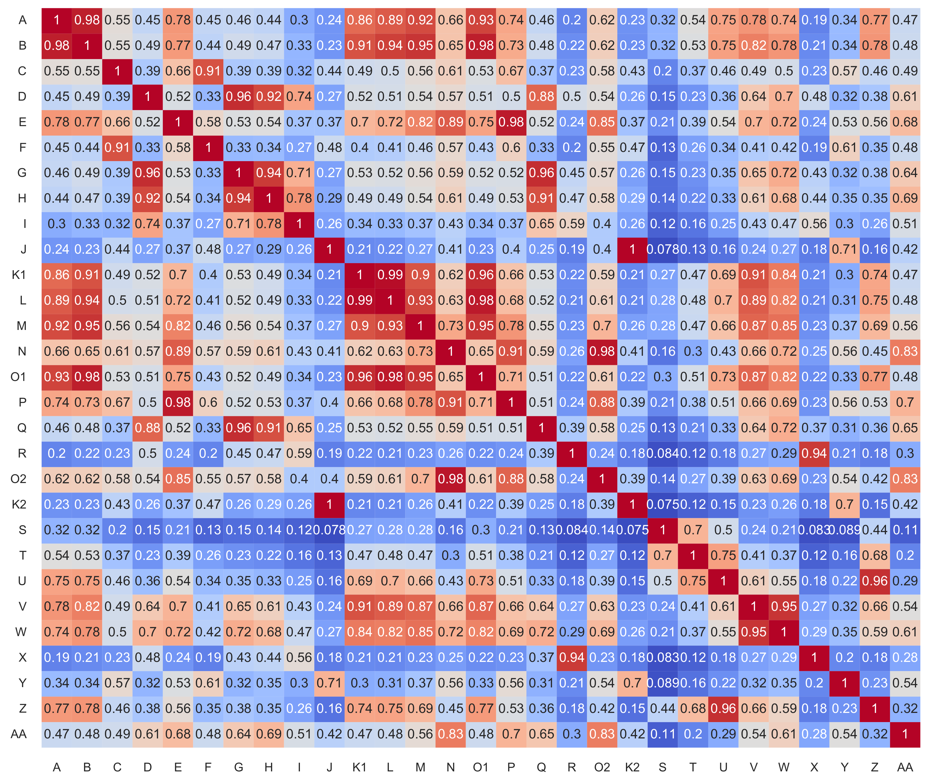
3.2. Dependence Patterns
4. Conclusions
Author Contributions
Funding
Institutional Review Board Statement
Informed Consent Statement
Data Availability Statement
Acknowledgments
Conflicts of Interest
Appendix A. Sources Information on Each Wind Farm

Appendix B. Descriptive Statistics for Various Time Horizons
Appendix B.1. Tables
| Mean | 0.25-Q | 0.5-Q | 0.75-Q | SD | R.-Power | Full-L. | Offs | Null | |
|---|---|---|---|---|---|---|---|---|---|
| A | 344.79 | 112.90 | 352.29 | 606.51 | 236.14 | 1741 | 4807 | 0 | 519 |
| B | 254.20 | 72.57 | 234.46 | 450.94 | 185.57 | 916 | 4430 | 0 | 484 |
| C | 252.54 | 48.99 | 201.47 | 475.16 | 211.03 | 621 | 3851 | 0 | 636 |
| D | 299.59 | 83.37 | 263.12 | 576.73 | 223.25 | 2073 | 4521 | 0 | 462 |
| E | 412.30 | 248.01 | 493.28 | 600.00 | 204.32 | 3065 | 6036 | 3 | 182 |
| F | 286.71 | 86.33 | 256.74 | 538.89 | 208.22 | 1950 | 4612 | 0 | 516 |
| G | 360.69 | 104.29 | 377.10 | 642.68 | 250.81 | 1853 | 4881 | 1 | 527 |
| H | 456.37 | 194.59 | 493.10 | 760.00 | 279.67 | 2369 | 5274 | 0 | 220 |
| I | 270.95 | 78.79 | 274.75 | 489.47 | 190.09 | 1971 | 4788 | 2 | 492 |
| J | 374.69 | 92.72 | 335.09 | 697.14 | 287.31 | 927 | 4323 | 1 | 632 |
| K1 | 305.48 | 81.07 | 298.45 | 550.93 | 222.47 | 1557 | 4563 | 0 | 595 |
| L | 454.37 | 169.26 | 533.23 | 752.00 | 285.74 | 2304 | 5307 | 1 | 470 |
| M | 277.42 | 103.44 | 319.37 | 464.00 | 175.70 | 2218 | 5251 | 1 | 484 |
| N | 371.11 | 115.21 | 358.96 | 668.18 | 264.69 | 1547 | 4565 | 2 | 482 |
| O1 | 686.70 | 210.98 | 710.80 | 1214.39 | 464.26 | 2085 | 4952 | 0 | 466 |
| P | 391.59 | 126.07 | 386.09 | 697.35 | 271.91 | 1662 | 4702 | 1 | 459 |
| Q | 531.29 | 163.14 | 522.94 | 943.24 | 373.00 | 1531 | 4678 | 0 | 495 |
| R | 322.41 | 107.55 | 343.74 | 568.82 | 218.31 | 1950 | 4916 | 3 | 611 |
| O2 | 825.74 | 310.27 | 997.41 | 1320.00 | 503.90 | 2708 | 5494 | 1 | 439 |
| K2 | 629.07 | 179.07 | 644.88 | 1124.15 | 441.91 | 1761 | 4767 | 0 | 558 |
| S | 230.64 | 53.46 | 198.06 | 417.05 | 182.44 | 1176 | 4084 | 0 | 699 |
| T | 246.05 | 63.29 | 232.37 | 441.86 | 185.09 | 1295 | 4357 | 2 | 543 |
| U | 271.14 | 62.38 | 227.58 | 502.86 | 216.39 | 1163 | 4099 | 0 | 630 |
| V | 857.17 | 273.62 | 897.53 | 1525.67 | 584.28 | 1994 | 4889 | 4 | 460 |
| W | 419.06 | 129.04 | 431.50 | 748.93 | 287.49 | 1938 | 4849 | 2 | 452 |
| X | 238.41 | 66.44 | 219.24 | 435.08 | 177.01 | 1493 | 4408 | 5 | 576 |
| Y | 559.23 | 146.60 | 579.13 | 1008.16 | 399.38 | 1728 | 4723 | 3 | 703 |
| Z | 258.05 | 63.18 | 249.20 | 471.11 | 191.12 | 1642 | 4569 | 1 | 648 |
| AA | 1490.85 | 521.42 | 1745.25 | 2470.00 | 950.97 | 2551 | 5301 | 23 | 411 |
| Total | 12,678.62 | 7247.01 | 12,416.40 | 18,591.27 | 6369.48 | 51,789 | 4847 | 56 | 14,851 |
| Mean | 0.25-Q | 0.5-Q | 0.75-Q | SD | R.-Power | Full-L. | Offs | Null | |
|---|---|---|---|---|---|---|---|---|---|
| A | 330.43 | 85.73 | 319.67 | 605.82 | 243.07 | 1745 | 4607 | 5 | 742 |
| B | 246.78 | 54.30 | 223.85 | 453.10 | 191.02 | 901 | 4300 | 11 | 763 |
| C | 237.91 | 31.05 | 164.75 | 466.70 | 216.39 | 670 | 3628 | 1 | 934 |
| D | 321.11 | 94.44 | 311.38 | 582.00 | 225.96 | 2274 | 4846 | 6 | 476 |
| E | 422.61 | 250.99 | 534.79 | 600.00 | 206.43 | 3453 | 6187 | 21 | 223 |
| F | 276.10 | 65.28 | 238.59 | 540.44 | 214.37 | 2033 | 4441 | 9 | 683 |
| G | 336.35 | 64.53 | 313.06 | 641.23 | 261.05 | 1926 | 4552 | 2 | 858 |
| H | 479.19 | 204.63 | 566.49 | 760.00 | 282.16 | 2660 | 5538 | 9 | 235 |
| I | 287.59 | 93.78 | 316.70 | 497.00 | 190.72 | 2224 | 5082 | 23 | 466 |
| J | 418.59 | 124.96 | 435.82 | 733.31 | 289.59 | 1211 | 4829 | 30 | 505 |
| K1 | 288.82 | 63.43 | 264.44 | 535.30 | 224.38 | 1527 | 4314 | 7 | 758 |
| L | 447.32 | 140.77 | 535.38 | 752.00 | 296.01 | 2413 | 5225 | 13 | 660 |
| M | 271.37 | 79.86 | 317.56 | 464.00 | 182.59 | 2303 | 5137 | 17 | 713 |
| N | 363.66 | 81.04 | 343.69 | 679.65 | 276.49 | 1647 | 4473 | 14 | 752 |
| O1 | 673.38 | 175.35 | 686.30 | 1218.00 | 481.72 | 2278 | 4856 | 12 | 608 |
| P | 383.41 | 96.02 | 377.91 | 705.43 | 281.27 | 1660 | 4604 | 15 | 723 |
| Q | 511.52 | 119.41 | 484.42 | 959.55 | 385.91 | 1739 | 4504 | 7 | 616 |
| R | 316.05 | 88.89 | 338.61 | 559.78 | 220.60 | 1774 | 4819 | 14 | 564 |
| O2 | 802.01 | 256.79 | 969.98 | 1320.00 | 523.91 | 2840 | 5337 | 13 | 586 |
| K2 | 594.70 | 140.48 | 572.58 | 1099.54 | 446.35 | 1723 | 4507 | 10 | 720 |
| S | 225.21 | 40.28 | 179.59 | 431.37 | 189.01 | 1296 | 3988 | 5 | 796 |
| T | 246.18 | 53.64 | 231.42 | 451.99 | 189.14 | 1367 | 4359 | 1 | 702 |
| U | 271.14 | 58.01 | 237.82 | 499.41 | 216.43 | 1230 | 4099 | 3 | 722 |
| V | 855.14 | 218.80 | 904.52 | 1535.63 | 602.40 | 2082 | 4877 | 28 | 577 |
| W | 417.46 | 100.27 | 442.30 | 757.59 | 298.64 | 2116 | 4831 | 24 | 608 |
| X | 235.90 | 59.80 | 229.77 | 423.12 | 176.58 | 1283 | 4362 | 14 | 610 |
| Y | 532.94 | 122.23 | 511.90 | 998.37 | 402.55 | 1770 | 4501 | 5 | 662 |
| Z | 257.78 | 61.86 | 257.75 | 470.46 | 190.55 | 1630 | 4565 | 4 | 755 |
| AA | 1470.09 | 469.18 | 1701.90 | 2470.00 | 969.33 | 2730 | 5228 | 46 | 487 |
| Total | 12,520.72 | 6594.40 | 12,598.43 | 18,722.44 | 6597.89 | 54,505 | 4786 | 369 | 18,504 |
| Mean | 0.25-Q | 0.5-Q | 0.75-Q | SD | R.-Power | Full-L. | Offs | Null | |
|---|---|---|---|---|---|---|---|---|---|
| A | 297.16 | 77.74 | 255.68 | 536.33 | 229.23 | 1033 | 4131 | 0 | 732 |
| B | 212.35 | 43.45 | 170.07 | 387.56 | 177.54 | 426 | 3690 | 0 | 743 |
| C | 179.36 | 25.02 | 106.46 | 287.69 | 186.03 | 296 | 2727 | 1 | 949 |
| D | 271.47 | 76.05 | 221.49 | 502.82 | 213.37 | 1451 | 4086 | 3 | 616 |
| E | 390.13 | 221.71 | 436.01 | 600.00 | 204.11 | 2312 | 5695 | 11 | 217 |
| F | 234.95 | 54.89 | 177.55 | 422.18 | 198.55 | 1237 | 3769 | 3 | 637 |
| G | 278.97 | 50.50 | 211.46 | 543.57 | 242.27 | 966 | 3765 | 14 | 837 |
| H | 422.74 | 169.20 | 418.22 | 726.73 | 273.73 | 1702 | 4872 | 6 | 250 |
| I | 251.39 | 73.50 | 239.53 | 446.43 | 182.78 | 1395 | 4431 | 4 | 520 |
| J | 371.75 | 89.82 | 350.85 | 663.05 | 279.64 | 525 | 4277 | 0 | 614 |
| K1 | 262.12 | 44.47 | 212.56 | 495.58 | 221.59 | 1239 | 3905 | 1 | 889 |
| L | 387.62 | 95.81 | 375.97 | 703.41 | 287.56 | 1489 | 4515 | 1 | 684 |
| M | 236.13 | 56.44 | 224.64 | 429.94 | 176.83 | 1420 | 4458 | 0 | 692 |
| N | 308.75 | 70.03 | 250.92 | 545.66 | 254.13 | 892 | 3788 | 2 | 671 |
| O1 | 579.98 | 138.60 | 500.78 | 1066.14 | 453.45 | 1358 | 4171 | 8 | 544 |
| P | 327.25 | 73.12 | 274.23 | 587.32 | 264.07 | 944 | 3918 | 0 | 669 |
| Q | 438.56 | 98.34 | 354.71 | 785.40 | 359.21 | 979 | 3851 | 0 | 564 |
| R | 308.15 | 80.08 | 322.51 | 555.51 | 222.81 | 1694 | 4686 | 0 | 745 |
| O2 | 715.67 | 200.20 | 739.36 | 1285.54 | 507.17 | 1864 | 4749 | 9 | 519 |
| K2 | 541.84 | 99.30 | 463.71 | 1031.34 | 442.61 | 1410 | 4095 | 3 | 836 |
| S | 222.43 | 50.26 | 185.14 | 401.77 | 179.76 | 992 | 3928 | 5 | 621 |
| T | 228.96 | 57.56 | 194.90 | 410.06 | 179.97 | 950 | 4043 | 0 | 609 |
| U | 239.08 | 53.91 | 186.55 | 419.59 | 202.60 | 731 | 3604 | 0 | 697 |
| V | 709.00 | 178.53 | 593.40 | 1292.82 | 564.10 | 1197 | 4033 | 9 | 592 |
| W | 351.20 | 88.85 | 298.82 | 628.08 | 277.06 | 1200 | 4053 | 8 | 545 |
| X | 233.55 | 52.78 | 217.79 | 427.16 | 179.11 | 1299 | 4307 | 0 | 733 |
| Y | 501.54 | 120.08 | 457.87 | 904.03 | 385.89 | 1238 | 4224 | 0 | 748 |
| Z | 226.93 | 46.91 | 192.11 | 412.96 | 182.42 | 1017 | 4007 | 0 | 759 |
| AA | 1304.99 | 380.17 | 1239.56 | 2408.34 | 938.00 | 1868 | 4628 | 12 | 444 |
| Total | 11,034.01 | 6089.92 | 10,368.24 | 15,676.43 | 5770.34 | 35,124 | 4206 | 100 | 18,676 |
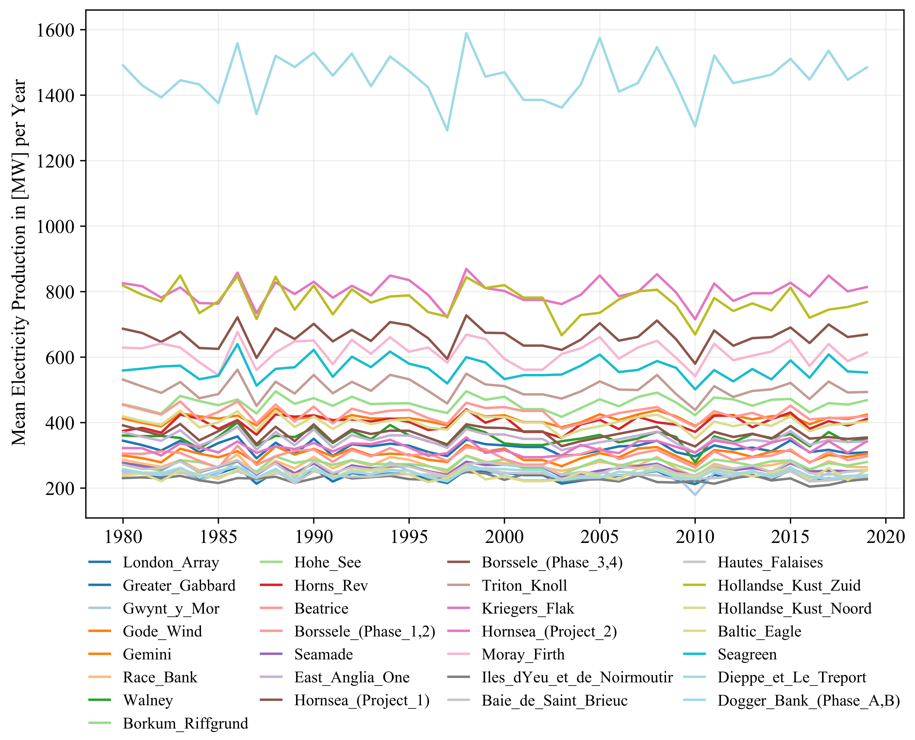
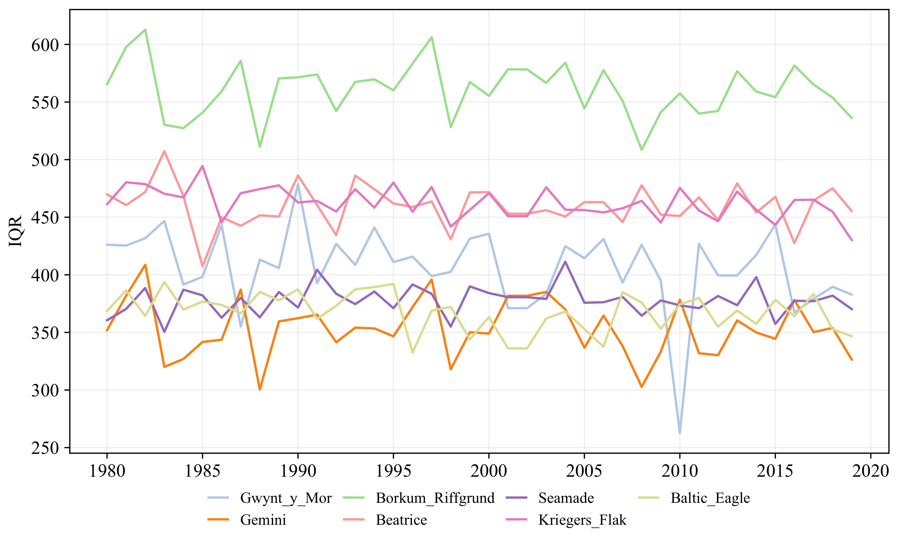
Appendix B.2. Figures


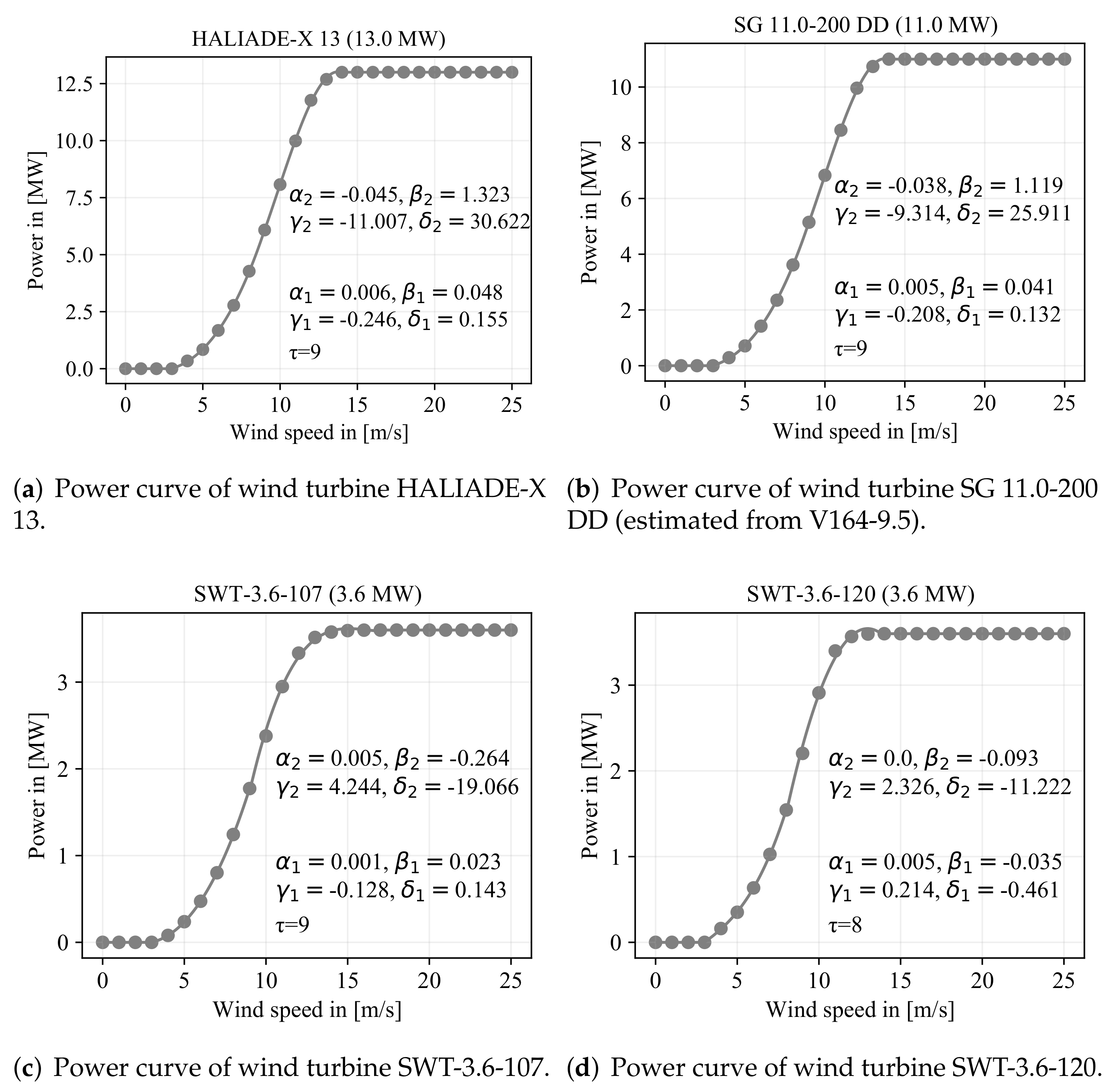
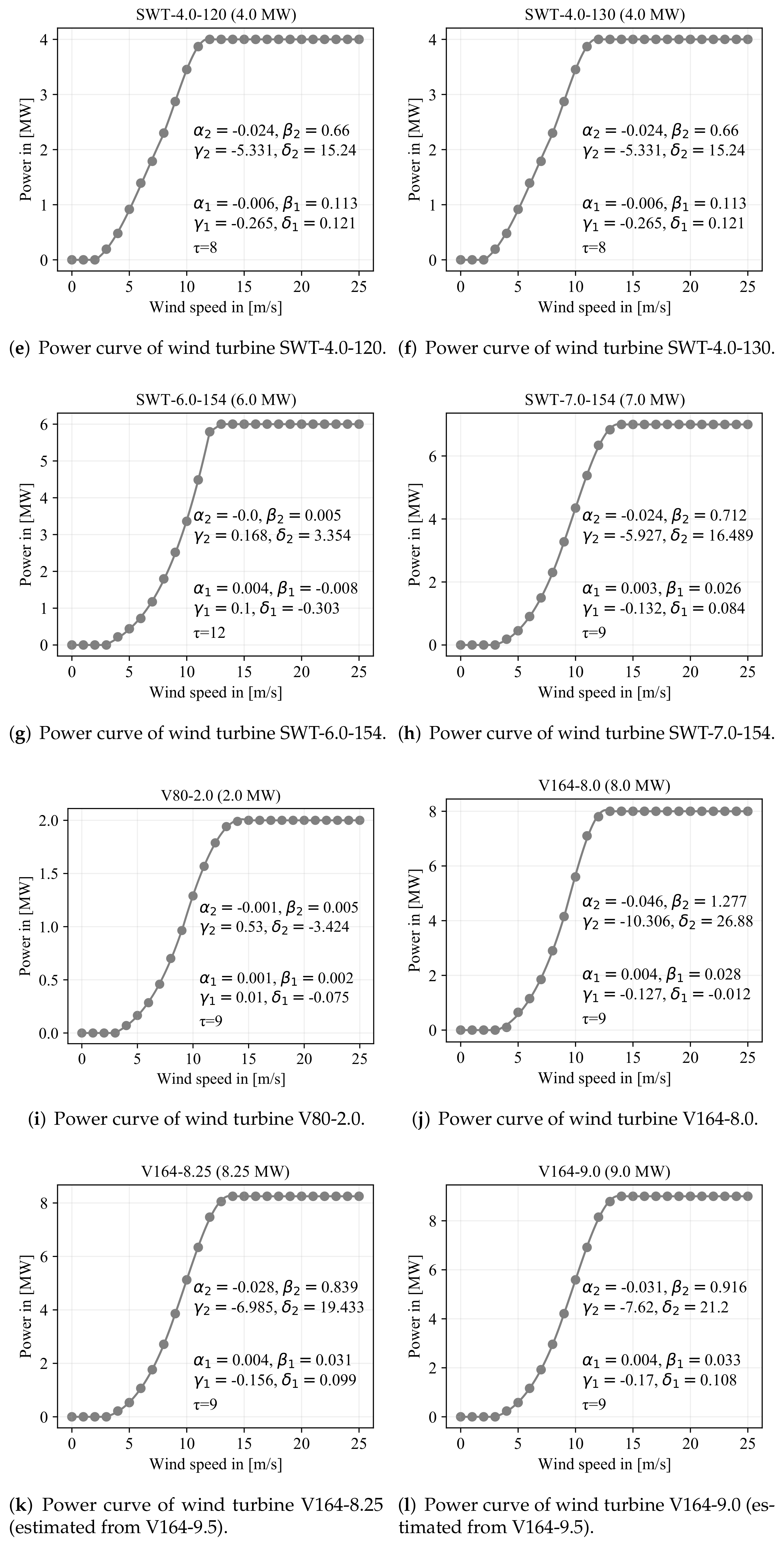
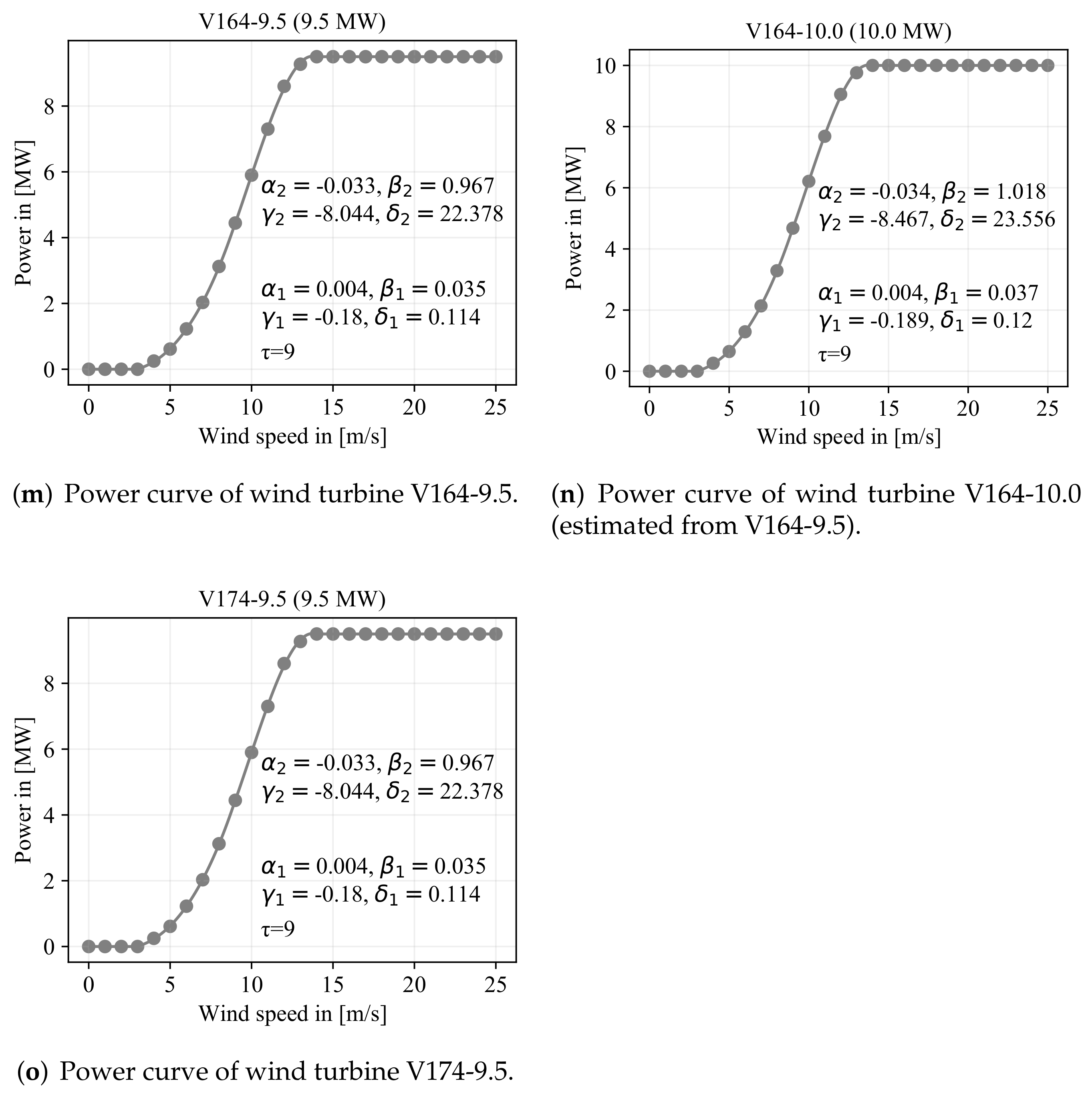
Appendix C. Power Curves of Wind Turbines


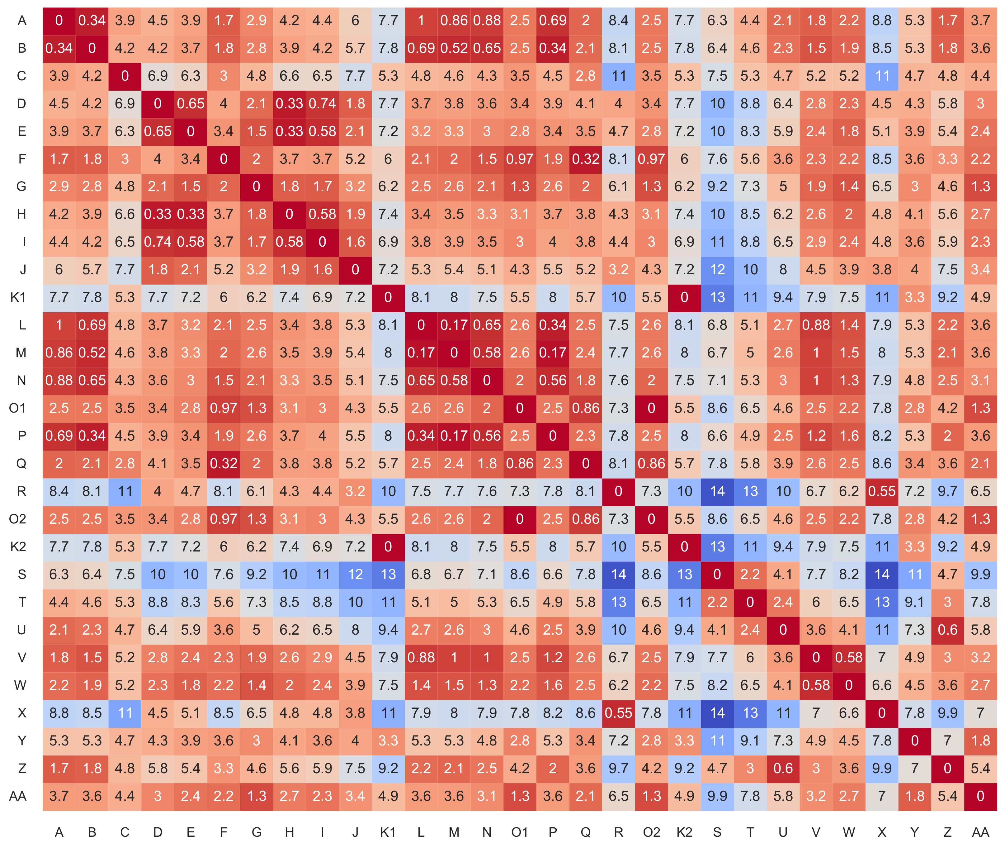
Appendix D. Distance Matrix of Wind Farms

References
- EU. Communication from the Commission to the European Parliament, the Council, the European Economic and Social Committee and the Committee of the Regions an EU Strategy to Harness the Potential of Offshore Renewable Energy for a Climate Neutral Future. Available online: https://ec.europa.eu/energy/topics/renewable-energy/eu-strategy-offshore-renewable-energy_en (accessed on 23 December 2021).
- EU. Communication from the Commission to the European Parliament, the Council, the European Economic and Social Committee and the Committee of the Regions the European Green Deal. Available online: https://eur-lex.europa.eu/legal-content/EN/TXT/?qid=1576150542719&uri=COM%3A2019%3A640%3AFIN (accessed on 29 December 2021).
- IEA. World Energy Outlook 2021. Available online: https://www.iea.org/reports/world-energy-outlook-2021 (accessed on 29 December 2021).
- European Commission; Joint Research Center (JRC). Enspreso—Wind—Onshore and Offshore. Available online: http://data.europa.eu/89h/6d0774ec-4fe5-4ca3-8564-626f4927744e (accessed on 29 December 2021).
- European Commission; Joint Research Centre; Tarvydas, D.; Politis, S.; Volker, P.; Medarac, H.; Dalla Longa, F.; Badger, J.; Kober, T.; Nijs, W.; et al. Wind Potentials for EU and Neighbouring Countries: Input Datasets for the JRC-EU-TIMES Model; Publications Office: Luxembourg, 2018. [Google Scholar]
- Hirth, L. The market value of variable renewables. The effect of solar wind power variability on their relative price. Energy Econ. 2013, 38, 218–236. [Google Scholar] [CrossRef] [Green Version]
- Jansen, M.F.; Staffell, I.; Kitzing, L.; Quoilin, S.; Wiggelinkhuizen, E.J.; Bulder, B.; Riepin, I.; Müsgens, F. Offshore wind competitiveness in mature markets without subsidy. Nat. Energy 2020, 5, 614–622. [Google Scholar] [CrossRef]
- Kitzing, L.; Juul, N.; Drud, M.; Boomsma, T.K. A real options approach to analyse wind energy investments under different support schemes. Appl. Energy 2017, 188, 83–96. [Google Scholar] [CrossRef]
- Hirth, L.; Radebach, A. The Market Value of Wind and Solar Power: An Analytical Approach. SSRN Electron. J. 2018, 38, 218–236. [Google Scholar] [CrossRef]
- Beiter, P.; Cooperman, A.; Lantz, E.; Stehly, T.; Shields, M.; Wiser, R.; Telsnig, T.; Kitzing, L.; Berkhout, V.; Kikuchi, Y. Wind power costs driven by innovation and experience with further reductions on the horizon. Wiley Interdiscip. Rev. Energy Environ. 2021, 10, e398. [Google Scholar] [CrossRef]
- Weigt, H.; von Hirschhausen, C. Price formation and market power in the German wholesale electricity market in 2006. Energy Policy 2008, 36, 4227–4234. [Google Scholar] [CrossRef] [Green Version]
- Möst, D.; Genoese, M. Market power in the German wholesale electricity market. J. Energy Mark. 2009, 2, 47–74. [Google Scholar] [CrossRef]
- Keles, D.; Genoese, M.; Möst, D.; Ortlieb, S.; Fichtner, W. A combined modeling approach for wind power feed-in and electricity spot prices. Energy Policy 2013, 59, 213–225. [Google Scholar] [CrossRef]
- Gil, H.A.; Gomez-Quiles, C.; Riquelme, J. Large-scale wind power integration and wholesale electricity trading benefits: Estimation via an ex post approach. Energy Policy 2012, 41, 849–859. [Google Scholar] [CrossRef]
- Paraschiv, F.; Erni, D.; Pietsch, R. The impact of renewable energies on EEX day-ahead electricity prices. Energy Policy 2014, 73, 196–210. [Google Scholar] [CrossRef] [Green Version]
- Pape, C.; Hagemann, S.; Weber, C. Are fundamentals enough? Explaining price variations in the German day-ahead and intraday power market. Energy Econ. 2016, 54, 376–387. [Google Scholar] [CrossRef] [Green Version]
- Antweiler, W.; Muesgens, F. On the long-term merit order effect of renewable energies. Energy Econ. 2021, 99, 105275. [Google Scholar] [CrossRef]
- Beran, P.; Pape, C.; Weber, C. Modelling German electricity wholesale spot prices with a parsimonious fundamental model—Validation & application. Util. Policy 2019, 58, 27–39. [Google Scholar]
- Gea-Bermudez, J.; Kitzing, L.; Matti, K.; Kaushik, D.; León, J.P.M.; Sørensen, P. The Influence of Large-Scale Wind Farm Wake Losses and Sector Coupling on the Development of Offshore Grids. SSRN Electron. J. 2021; Preprint. [Google Scholar] [CrossRef]
- Wang, N.; Zhou, K.P.; Wang, K.; Feng, T.; Zhang, Y.H.; Song, C.H. Climate Change Characteristics of Coastal Wind Energy Resources in Zhejiang Province Based on ERA-Interim Data. Front. Phys. 2021, 9, 696. [Google Scholar] [CrossRef]
- Pryor, S.C.; Barthelmie, R.J. Climate change impacts on wind energy: A review. Renew. Sustain. Energy Rev. 2010, 14, 430–437. [Google Scholar] [CrossRef]
- Gernaat, D.E.; de Boer, H.S.; Daioglou, V.; Yalew, S.G.; Müller, C.; van Vuuren, D.P. Climate change impacts on renewable energy supply. Nat. Clim. Chang. 2021, 11, 119–125. [Google Scholar] [CrossRef]
- Koivisto, M.; Jónsdóttir, G.M.; Sørensen, P.; Plakas, K.; Cutululis, N. Combination of meteorological reanalysis data and stochastic simulation for modelling wind generation variability. Renew. Energy 2020, 159, 991–999. [Google Scholar] [CrossRef]
- Ruiz, P.; Nijs, W.; Tarvydas, D.; Sgobbi, A.; Zucker, A.; Pilli, R.; Jonsson, R.; Camia, A.; Thiel, C.; Hoyer-Klick, C.; et al. ENSPRESO—An open, EU-28 wide, transparent and coherent database of wind, solar and biomass energy potentials. Energy Strategy Rev. 2019, 26, 100379. [Google Scholar] [CrossRef]
- Olauson, J.; Bergkvist, M. Modelling the Swedish wind power production using MERRA reanalysis data. Renew. Energy 2015, 76, 717–725. [Google Scholar] [CrossRef]
- Koivisto, M.; Ekström, J.; Seppänen, J.; Mellin, I.; Millar, J.; Haarla, L. A statistical model for comparing future wind power scenarios with varying geographical distribution of installed generation capacity. Wind Energy 2016, 19, 665–679. [Google Scholar] [CrossRef]
- Jensen, T.V.; Pinson, P. RE-Europe, a large-scale dataset for modeling a highly renewable European electricity system. Sci. Data 2017, 4, 170175. [Google Scholar] [CrossRef] [Green Version]
- Andresen, G.B.; Rodriguez, R.A.; Becker, S.; Greiner, M. The potential for arbitrage of wind and solar surplus power in Denmark. Energy 2014, 76, 49–58. [Google Scholar] [CrossRef]
- Gupta, R.; Shankar, H. Global Energy Observatory. Available online: http://www.globalenergyobservatory.com/index.php (accessed on 12 January 2021).
- Wiese, F.; Schlecht, I.; Bunke, W.D.; Gerbaulet, C.; Hirth, L.; Jahn, M.; Kunz, F.; Lorenz, C.; Mühlenpfordt, J.; Reimann, J.; et al. Open Power System Data—Frictionless data for electricity system modelling. Appl. Energy 2019, 236, 401–409. [Google Scholar] [CrossRef] [Green Version]
- Engelhorn, T.; Müsgens, F. How to estimate wind-turbine infeed with incomplete stock data: A general framework with an application to turbine-specific market values in Germany. Energy Econ. 2018, 72, 542–557. [Google Scholar]
- Katzenstein, W.; Fertig, E.; Apt, J. The variability of interconnected wind plants. Energy Policy 2010, 38, 4400–4410. [Google Scholar] [CrossRef]
- Giebel, G. On the Benefits of Distributed Generation of Wind Energy in Europe. Masters’s Thesis, Carl von Ossietzky Universitat Oldenburg, Oldenburg, Germany, 2000. [Google Scholar]
- Grothe, O.; Schnieders, J. Spatial dependence in wind and optimal wind power allocation: A copula-based analysis. Energy Policy 2011, 39, 4742–4754. [Google Scholar] [CrossRef] [Green Version]
- Hersbach, H.; Bell, B.; Berrisford, P.; Biavati, G.; Horányi, A.; Sabater, J.M.; Nicolas, J.; Peubey, C.; Radu, R.; Rozum, I.; et al. ERA5 Hourly Data on Single Levels from 1979 to Present. Copernicus Climate Change Service (C3S) Climate Data Store (CDS). 2018. Available online: https://cds.climate.copernicus.eu/cdsapp#!/dataset/reanalysis-era5-single-levels?tab=overview (accessed on 29 October 2021).
- Grothe, O.; Müsgens, F. The influence of spatial effects on wind power revenues under direct marketing rules. Energy Policy 2013, 58, 237–247. [Google Scholar] [CrossRef] [Green Version]
- Seinfeld, J.H.; Pandis, S.N. Atmospheric Chemistry and Physics: From Air Pollution to Climate Change, 3rd ed.; John Wiley & Sons: Hoboken, NJ, USA, 2016. [Google Scholar]
- Archer, C.L.; Jacobson, M.Z. Supplying Baseload Power and Reducing Transmission Requirements by Interconnecting Wind Farms. J. Appl. Meteorol. Climatol. 2007, 46, 1701–1717. [Google Scholar] [CrossRef] [Green Version]
- Göçmen, T.; van der Laan, P.; Réthoré, P.E.; Diaz, A.P.; Larsen, G.C.; Ott, S. Wind turbine wake models developed at the technical university of Denmark: A review. Renew. Sustain. Energy Rev. 2016, 60, 752–769. [Google Scholar] [CrossRef] [Green Version]
- Archer, C.L.; Vasel-Be-Hagh, A.; Yan, C.; Wu, S.; Pan, Y.; Brodie, J.F.; Maguire, A.E. Review and evaluation of wake loss models for wind energy applications. Appl. Energy 2018, 226, 1187–1207. [Google Scholar] [CrossRef]
- Crespo, A.; Hernández, J.; Frandsen, S. Survey of modelling methods for wind turbine wakes and wind farms. Wind Energy 1999, 2, 1–24. [Google Scholar] [CrossRef]
- Santos-Alamillos, F.; Thomaidis, N.; Usaola-García, J.; Ruiz-Arias, J.; Pozo-Vázquez, D. Exploring the mean-variance portfolio optimization approach for planning wind repowering actions in Spain. Renew. Energy 2017, 106, 335–342. [Google Scholar] [CrossRef]
- Ziel, F.; Weron, R. Day-ahead electricity price forecasting with high-dimensional structures: Univariate vs. multivariate modeling frameworks. Energy Econ. 2018, 70, 396–420. [Google Scholar] [CrossRef] [Green Version]
- Chai, S.; Xu, Z.; Jia, Y. Conditional Density Forecast of Electricity Price Based on Ensemble ELM and Logistic EMOS. IEEE Trans. Smart Grid 2019, 10, 3031–3043. [Google Scholar] [CrossRef]
- Janke, T.; Steinke, F. Probabilistic multivariate electricity price forecasting using implicit generative ensemble post-processing. In Proceedings of the 2020 International Conference on Probabilistic Methods Applied to Power Systems (PMAPS), Liege, Belgium, 18–21 August 2020. [Google Scholar]
- Grothe, O.; Kächele, F.; Krüger, F. From Point Forecasts to Multivariate Probabilistic Forecasts: The Schaake Shuffle for Day-Ahead Electricity Price Forecasting; Working Paper; Karlsruhe Institute of Technology (KIT): Karlsruhe, Germany, 2022. [Google Scholar]


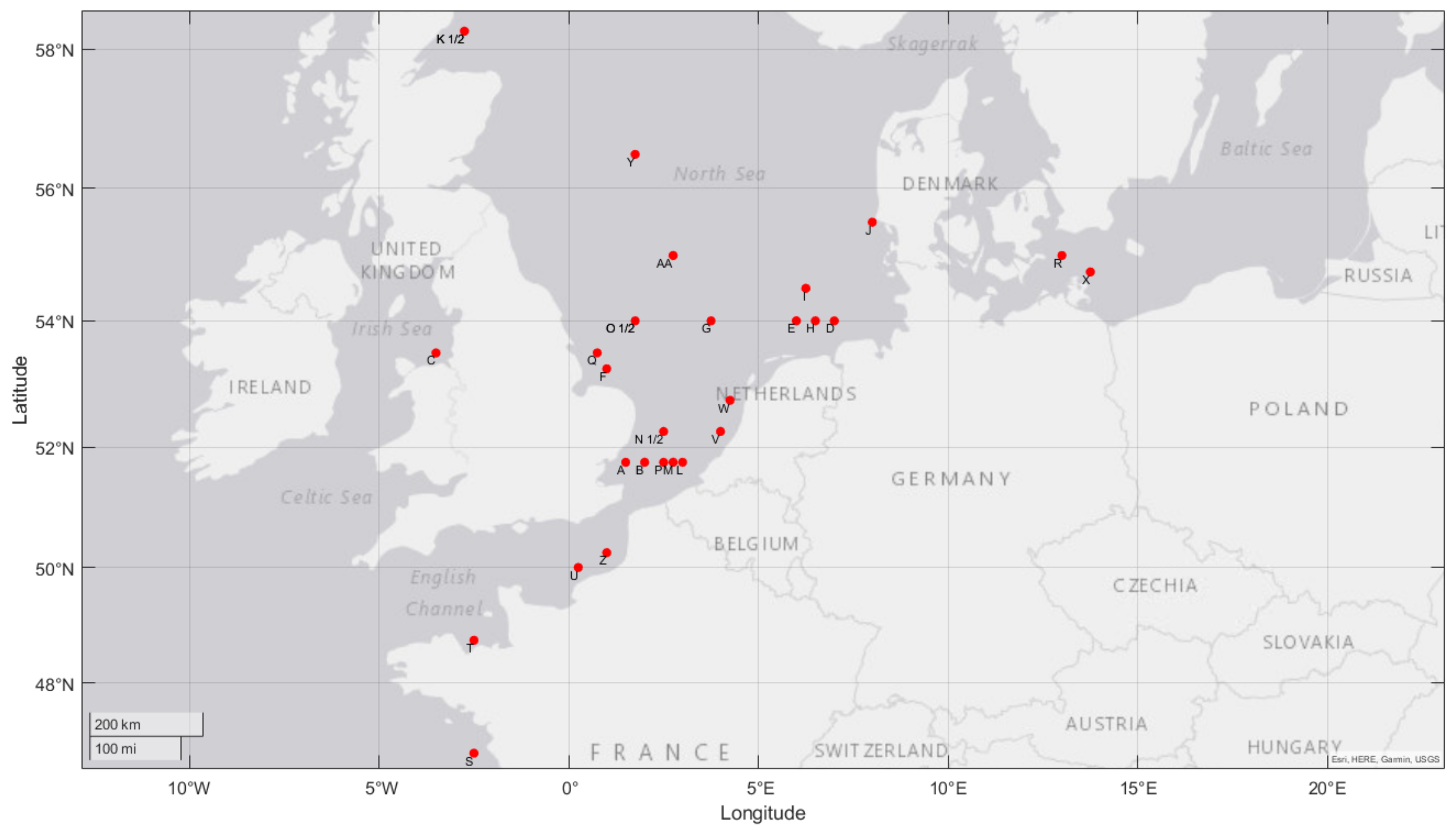
| Letter | Wind Farm | Lat. * | Long. ** | Hub (m) | Turbine | MW | Year |
|---|---|---|---|---|---|---|---|
| A | London Array | 51.75 | 1.5 | 87 | SWT-3.6-120 | 630 | 2012 |
| B | Greater Gabbard | 51.75 | 2 | 78 | SWT-3.6-107 | 504 | 2012 |
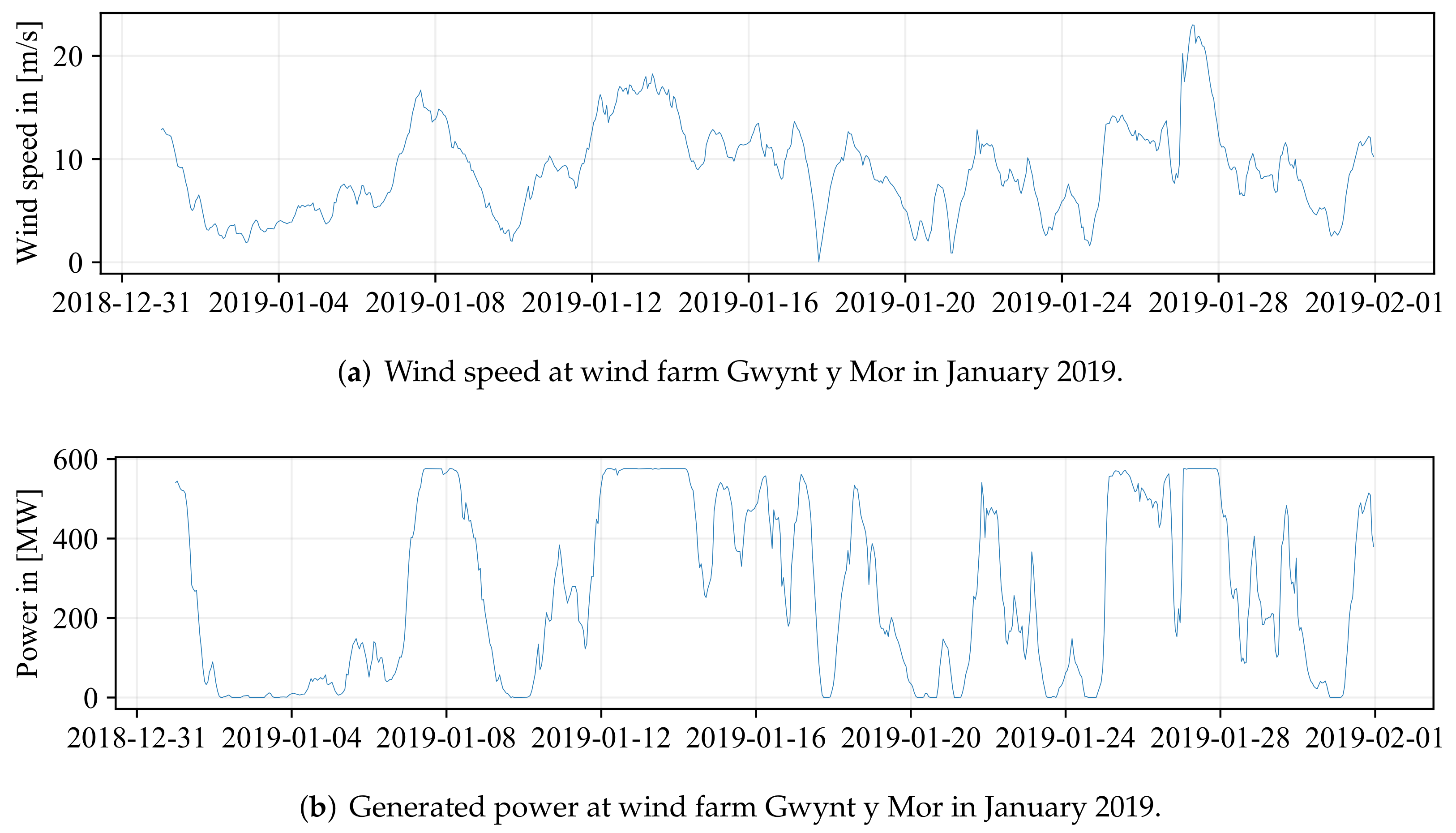
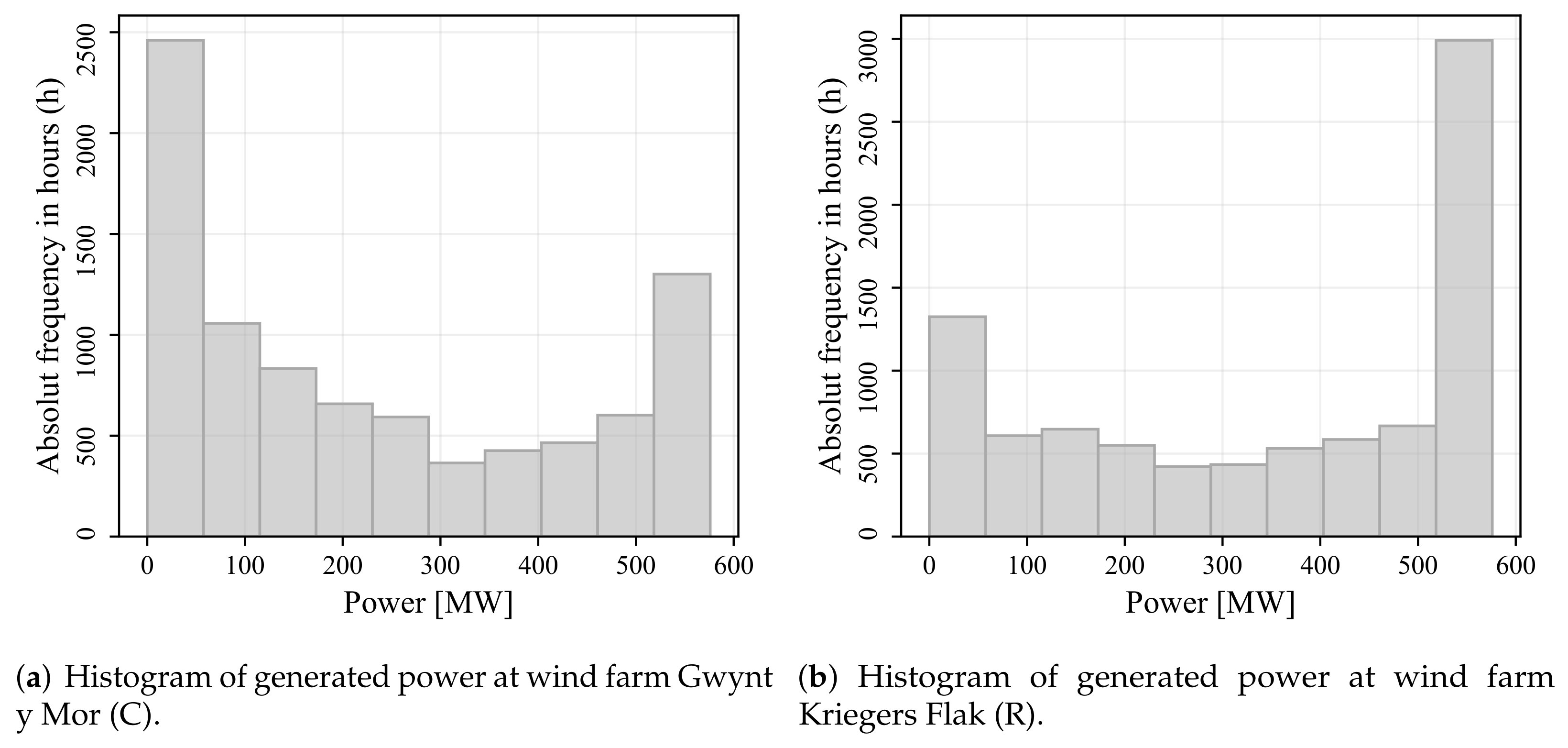
| C | Gwynt y Mor | 53.5 | −3.5 | 84.4 | SWT-3.6-107 | 576 | 2015 |
| D | Gode Wind (1&2) | 54 | 7 | - | SWT-6.0-154 | 582 | 2016 |
| E | Gemini | 54 | 6 | 120 | SWT-4.0.130 | 600 | 2017 |
| F | Race Bank | 53.25 | 1 | 100 | SWT-6.0-154 | 573 | 2018 |
| G | Walney Extension | 54 | 3.75 | 113 | V164-8.25 | 659 | 2018 |
| 111 | SWT-7.0-154 | ||||||
| H | Borkum Riffgrund 1&2 | 54 | 6.5 | - | SWT-4.0-120 | 767 | 2019 |
| - | V164-9.0 | ||||||
| I | Hohe See | 54.5 | 6.25 | 105 | SWT-7.0-154 | 479 | 2019 |
| J | Horns Rev Phase 1–3 | 55.5 | 8 | 70 | V80-2.0 | 774 | 2019 |
| 68 | SWT-2.3-93 | ||||||
| - | V164-8.3 | ||||||
| K1 | Beatrice | 58.25 | −2.75 | 90 | SWT-7.0-154 | 588 | 2019 |
| L | Borssele Phase 1&2 | 51.75 | 3 | 116.5 | SG 8.0-167 DD | 752 | 2020 |
| M | Seamade | 51.75 | 2.75 | 109 | SG 8.0-167 DD | 487 | 2020 |
| N | East Anglia One | 52.25 | 2.5 | 90.5 | SWT-7.0-154 | 714 | 2020 |
| O1 | Hornsea (Project 1) | 54 | 1.75 | 113 | SWT-7.0-154 | 1218 | 2020 |
| P | Borssele Phase 3&4 | 51.75 | 2.5 | - | V164-9.5 | 731.5 | 2021 |
| Q | Triton Knoll | 53.5 | 0.75 | 105 | V164-9.5 | 857 | 2021 |
| R | Kriegers Flak | 55 | 13 | 104.5 | SG 8.0-167 DD | 604 | 2021 |
| O2 | Hornsea (Project 2) | 54 | 1.75 | 123.5 | SG 8.0-167 DD | 1386 | 2022 |
| K2 | Moray Firth (East) | 58.25 | −2.75 | 122 | V164-9.5 | 950 | 2022 |
| S | Iles dYeu et de Noirmoutir | 46.75 | −2.5 | - | SG 8.0-167 DD | 500 | 2023 |
| T | Baie de Saint Brieuc | 48.75 | −2.5 | 123.5 | SG 8.0-167 DD | 496 | 2023 |
| U | Hautes Falaises | 50 | 0.25 | - | SWT-7.0-154 | 500 | 2023 |
| V | Hollandse Kust Zuid | 52.25 | 4 | 125.5 | SG 11.0-200 DD | 1500 | 2023 |
| W | Hollandse Kust Noord | 52.75 | 4.25 | 125.5 | SG 11.0-200 DD | 759 | 2023 |
| X | Baltic Eagle | 54.75 | 13.75 | 107 | V174-9.5 | 476 | 2023 |
| Y | Seagreen | 56.5 | 1.75 | 104 | V164-10.0 | 1075 | 2023 |
| Z | Dieppe et Le Treport | 50.25 | 1 | - | SG 8.0-167 DD | 496 | 2024 |
| AA | Dogger Bank (Phase A, B) | 55 | 2.75 | 150 | HALIADE-X 13 | 2400 | 2024 |
| Mean | 0.25-Q | 0.5-Q | 0.75-Q | SD | R.-Power | Full-L. | Offs | Null | |
|---|---|---|---|---|---|---|---|---|---|
| A | 309.22 | 82.33 | 264.52 | 564.60 | 235.60 | 1342 | 4299 | 0 | 629 |
| B | 227.07 | 50.65 | 183.28 | 420.21 | 184.01 | 668 | 3946 | 0 | 637 |
| C | 232.85 | 45.81 | 175.18 | 428.66 | 202.24 | 431 | 3541 | 1 | 789 |
| D | 305.07 | 103.43 | 274.92 | 569.18 | 214.31 | 1829 | 4591 | 2 | 388 |
| E | 424.30 | 273.57 | 502.65 | 600.00 | 193.22 | 2894 | 6194 | 5 | 137 |
| F | 263.68 | 68.66 | 224.43 | 504.85 | 204.23 | 1456 | 4230 | 3 | 577 |
| G | 351.81 | 101.01 | 353.45 | 632.60 | 249.42 | 1614 | 4748 | 7 | 557 |
| H | 468.39 | 223.50 | 505.05 | 759.62 | 267.20 | 2161 | 5398 | 1 | 148 |
| I | 279.68 | 105.21 | 294.44 | 479.04 | 180.07 | 1716 | 4929 | 4 | 330 |
| J | 410.99 | 146.14 | 412.98 | 706.55 | 275.52 | 834 | 4729 | 0 | 454 |
| K1 | 297.17 | 78.12 | 286.53 | 533.44 | 219.70 | 1252 | 4427 | 2 | 612 |
| L | 420.03 | 140.12 | 442.84 | 740.94 | 285.04 | 1932 | 4892 | 1 | 568 |
| M | 254.50 | 82.42 | 258.32 | 452.66 | 176.10 | 1864 | 4804 | 1 | 570 |
| N | 342.61 | 91.59 | 302.09 | 615.06 | 261.90 | 1213 | 4203 | 0 | 566 |
| O1 | 669.02 | 228.69 | 690.83 | 1161.78 | 452.20 | 1569 | 4811 | 4 | 425 |
| P | 354.64 | 96.78 | 303.16 | 643.89 | 269.99 | 1340 | 4246 | 1 | 557 |
| Q | 493.57 | 129.64 | 463.92 | 873.43 | 365.55 | 1119 | 4334 | 4 | 563 |
| R | 342.72 | 139.59 | 389.24 | 569.80 | 212.61 | 1944 | 5212 | 2 | 458 |
| O2 | 814.13 | 334.09 | 975.33 | 1320.00 | 496.63 | 2287 | 5402 | 10 | 413 |
| K2 | 613.67 | 172.48 | 619.16 | 1096.67 | 438.12 | 1485 | 4638 | 4 | 577 |
| S | 227.62 | 47.77 | 181.17 | 428.48 | 187.17 | 1249 | 4020 | 12 | 669 |
| T | 236.30 | 50.50 | 191.57 | 450.93 | 190.38 | 1413 | 4173 | 0 | 639 |
| U | 254.71 | 48.05 | 194.52 | 484.49 | 217.84 | 1243 | 3840 | 0 | 690 |
| V | 809.81 | 268.75 | 763.13 | 1464.19 | 568.92 | 1663 | 4606 | 0 | 458 |
| W | 403.58 | 132.63 | 385.69 | 721.04 | 280.92 | 1593 | 4657 | 0 | 473 |
| X | 254.79 | 92.22 | 255.60 | 438.86 | 171.12 | 1420 | 4698 | 2 | 428 |
| Y | 553.12 | 175.93 | 558.39 | 967.58 | 383.88 | 1461 | 4659 | 0 | 480 |
| Z | 240.02 | 52.90 | 203.74 | 456.83 | 190.66 | 1547 | 4238 | 0 | 670 |
| AA | 1484.73 | 602.79 | 1651.06 | 2469.39 | 913.42 | 2171 | 5265 | 30 | 315 |
| Total | 12,339.82 | 7429.56 | 12,012.46 | 17,489.41 | 5901.58 | 44,710 | 4704 | 96 | 14,777 |
Publisher’s Note: MDPI stays neutral with regard to jurisdictional claims in published maps and institutional affiliations. |
© 2022 by the authors. Licensee MDPI, Basel, Switzerland. This article is an open access article distributed under the terms and conditions of the Creative Commons Attribution (CC BY) license (https://creativecommons.org/licenses/by/4.0/).
Share and Cite
Grothe, O.; Kächele, F.; Watermeyer, M. Analyzing Europe’s Biggest Offshore Wind Farms: A Data Set with 40 Years of Hourly Wind Speeds and Electricity Production. Energies 2022, 15, 1700. https://doi.org/10.3390/en15051700
Grothe O, Kächele F, Watermeyer M. Analyzing Europe’s Biggest Offshore Wind Farms: A Data Set with 40 Years of Hourly Wind Speeds and Electricity Production. Energies. 2022; 15(5):1700. https://doi.org/10.3390/en15051700
Chicago/Turabian StyleGrothe, Oliver, Fabian Kächele, and Mira Watermeyer. 2022. "Analyzing Europe’s Biggest Offshore Wind Farms: A Data Set with 40 Years of Hourly Wind Speeds and Electricity Production" Energies 15, no. 5: 1700. https://doi.org/10.3390/en15051700
APA StyleGrothe, O., Kächele, F., & Watermeyer, M. (2022). Analyzing Europe’s Biggest Offshore Wind Farms: A Data Set with 40 Years of Hourly Wind Speeds and Electricity Production. Energies, 15(5), 1700. https://doi.org/10.3390/en15051700