1. Introduction
Research on high-speed electrical machines is a trend towards higher power density. One application of interest is the flywheel. Flywheels are devices used to store energy in the kinetic form and make it available in occasional failure of the main supply system. This device was studied with superconductor magnetic bearings for better efficiency [
1] and was addressed by recent research [
2,
3]. However, the prototype still lacks sensorless control to remove the position encoder and overcome the limited operational speed. This paper proposes a sensorless method for the application as Flywheel and extends the results presented in [
4].
Flywheel structure can assume three main categories: two-body, one-body or concentric. Flywheels that operate at high speeds are encapsulated in vacuum vessels and are usually composed of two-body or concentric structures. High-speed flywheels are competitive devices to achieve high efficiency, energy, and power densities [
5]. Low-speed flywheels assembled with a one-body structure are more cost-effective but limited in energy and power density. The flywheel of particular interest has a concentric structure and was designed for a switched reluctance machine (SRM) in [
6]. The main advantage is its simple structure. The rotor is solid; the windings are concentrated-type and placed in the stator only. This structure promotes ease of manufacturing and reduces cost. The construction dispenses with the use of cage bars or flux barriers, which comes as an advantage for a flywheel to reach the highest rotational speed with a given rotor diameter, targeted in this case to 50,000 rpm. The motivation to employ a concentric structure is to increase the moment of inertia for the same material. The external rotor contributes to a greater moment of inertia, and the rotor itself may assume the role of a flywheel. This design removes the wheel and simplifies the device’s mechanical project.
Some characteristics of SRMs are considered drawbacks, such as high torque ripple, loud acoustic noise, and a required position sensor to operate. External sensors may represent mechanical difficulties at high-speed applications, increasing the vulnerability to failures, cost, and size of the SRM [
7]. Therefore, the study of sensorless control is motivated by the challenge of overcoming this mechanical limitation. In that context, this paper proposes a sensorless method of position tracking to support the implementation of SRM flywheel speed control. The main idea of sensorless methods on SRMs is to use electrical parameters such as current, back-electromotive force (back-EMF), voltage, or inductance to estimate the rotor position. A common characteristic in all sensorless strategies is the relation of inductance to the rotor position. The main difference between the strategies relies on the machine speed because of its influence on back-EMF. At high speeds, the back-EMF is large enough to hold the decay of phase current. Thus, the conduction period is too large to implement idle phase methods. The basic principles of sensorless techniques are presented in [
8] and a summary of these approaches is given in [
9]. Sensorless methods at low speeds may explore inductance-based models [
10], the slope of electric current [
11], fuzzy observers [
12] and adaptive filters, as presented in [
13] or it can be estimated in idle phases by induction vectors, as presented in [
14], or by modulation, as in [
15]. The mutual coupling effect is considered in [
11,
16].
Sensorless methods at high speeds are often oriented by observer/filter or flux/current. One example of an observer-oriented approach is the general non-linear magnetizing model (GNMM) developed in [
17], which determined the machine position at speeds up to 20,000 rpm with experimental validation. The GNMM updates a defined position reference at critical points by the flux observation. The observer uses a normalized flux linkage profile to perform adaptive online reference tuning. The sensorless methods focused on the linked flux or the back-EMF are used in [
18,
19,
20,
21]. These methods intend to take advantage of SRM magnetic characteristics to find the shaft position and avoid great computational effort, common in observer approaches. A family of non-intrusive sensorless methods is presented in [
18] to discuss advantages and disadvantages. The main contribution of this work is the introduction of a “Discrete Position Sensing Scheme”, also called Simplified Flux Method. Its principles and fundamental equations are used to develop the machine model.
2. Mathematical Model
The SRM has particular magnetic characteristics caused by its constructional aspects. It is structured with salient poles in both iron parts: stator and rotor. Because of this double salient structure, the magnetic circuit reluctance changes along with the rotor position, assuming a minimum value when stator and rotor poles are aligned. It is a crucial quantity because the machine works exclusively with reluctance torque by its tendency to rotate the moving part towards minimum magnetic reluctance.
The self-inductance values can describe the generation of reluctance torque and the magnetic characterization of the SRM for each rotor position. This description is provided in FEM magneto-static simulations in previous work. The results are stored in a lookup table and used as the basis for the mathematical model of the machine.
A mathematical model is developed, considering the main construction and electrical characteristics. The machine response to the coil excitation is primarily derived from the Induction Law, stated in (
1).
Using a basic relationship between the flux linkage and current, i.e.,
Equation (
1) can be expressed as
Equation (
3) leads to the expression used within the algorithm of machine simulations,
where
is the angular speed in rad/s.
The electromagnetic torque is calculated from the partial derivative of the co-magnetic energy in relation to the position, according to the Equation (
5).
The developed torque can be calculated from the Equation (
6).
The incremental speed can be derived from Newton’s second law, as in (
7).
Considering the application as a flywheel, only the electromagnetic torque and the opposite wind friction are considered in the equation.
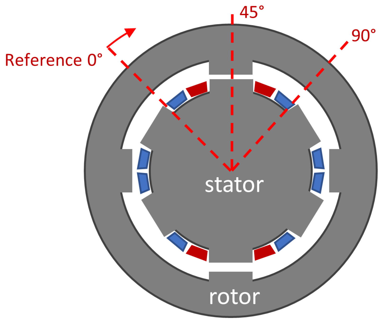
The reference defined for the rotor position assumes 45° where stator and rotor poles are aligned, as illustrated in
Figure 1. This reference is relative to the stator coils highlighted in dark red.
The machine has a 6/4 structure. This produces a symmetry that repeats for every quarter of rotation. Therefore, an angular interval from 0–90° defines a sufficient and complete reference for a phase coil.
The machine command is based on two firing angles within the angular interval. Coils are excited at a given position, known as the excitation angle () and the command applies a negative voltage on the coil at a specific position, called the commutation angle (), until current reaches zero.
Finally, the command relies on accurate position tracking, which depends greatly on a reliable model. In this work, the Finite Element Method (FEM) calculated the electromagnetic characteristics and non-linear effects of saturation by previous work in [
6]. The self-inductance values from FEM simulations are stored in lookup tables relating electric current, static flux linkage, and rotor position.
3. Sensorless Method
Sensorless methods are usually classified as active or passive, based on estimation strategy. At high speeds, active phases remain idle during only a small fraction of the time, and consequently, there is not enough time to make a test on idle conditions. As a result, passive methods are often more suitable for high-speed applications than active approaches.
Initially, two passive methods were considered to estimate position: the Flux Method and the Current Gradient Method (CGS). The CGS is limited to a specific position [
21],while the Flux Method applies to any mechanical position, assuming there is conducting current. The flux-linkage is built [
18]. For that reason, the flux method was chosen.
3.1. Concept of the Method
The flux method is based on the relation between linked-flux and the rotor position. From the Law of Induction, it is possible to deduce an integral expression to compute the linkage-flux. From (
1) we have that
Integrating both sides of Equation (
8) and describing the initial condition of magnetic flux at
as
, it leads to Equation (
9).
The relation between rotor position, linked-flux and electric current is described as a look-up table. The inputs are linked-flux and electric current; the output is the rotor position.
Simulations of the flux method resulted in errors larger than expected. The estimation error reached 9° as the rotor approached the aligned position. Comparing the maximum error to the stator poles arc (30 mechanical degrees) corresponds to a relative error of 30%. The cause for large error was investigated by comparing the true flux of the machine to linkage flux values stored in the lookup table. A mismatch appears between the calculated flux and the lookup table flux near the aligned position even in the non-saturated conditions.
The flux method did not present satisfactory results. Therefore, it was necessary to work with another approach. The flux/current method uses the value of linkage-flux to calculate the self-inductance of an active phase. The inductance is estimated by (
10).
The inductance is estimated for a single phase. It corresponds to the same phase coil of the flux and electric current. This method is performed in two variations. One is called sequential Flux/Current method and the second is referred as Robust Flux/Current Method. The Sequential Method consists of a constant estimation of the inductance and position. This variation provides many estimations, which can be useful for torque or speed control. The robust variation estimates the position of firing angles only. In this method, a certain inductance limit is defined by the position of interest, such as the commutation angle. When the estimated inductance reaches that limit, it is assumed that the position of inter-est is reached. One advantage of the Robust Method is its simplicity compared to the sequential variation, but it provides a limited number of position estimations.
The principle of both variation is concisely shown in Equations (
11) and (
12).
The equations indicate a conditional difference to estimate the position. In (
11), the estimation always occurs. However, in (
12), the position is estimated only if the defined limit
is reached. This difference is illustrated in
Figure 2a,b. The
Figure 2a shows that the Sequential Method estimates as many positions as possible for each electrical cycle while the Robust Method, illustrated in
Figure 2b, estimates a single position during the same time period.
3.2. Hybrid Simulation of the Method
The sensorless methods are assumed to be performed by a microprocessor. The simulation of these methods is done in a temporal discretization, while the voltage and current of the machine are treated as continuous quantities. The simulation is called hybrid because it deals with two different quantity types. The simulation represents a system with both continuous and discrete variables, as illustrated by
Figure 3.
The estimator model works with discrete quantities limited within the Microprocessor’s clock time. These quantities are modeled as zero-order hold, such that the acquired quantities in the estimator are updated at the pace of processing frequency. Therefore, linkage-flux and self-inductance are computed in the microprocessor and discrete quantities. The calculation of linkage-flux may reach errors near-zero value because the estimator cannot measure the subtle variations while the acquired measurements are on hold. To avoid cumulative errors in the flux-linkage estimation, a condition was applied to reset the calculated flux every time the electric current reached zero. The expression to calculate the flux is presented in Equation (
13), in which
is the time period of the estimator clock.
The inductance is estimated from the ratio between linkage-flux and electric current, which in discrete form is written as
A simple approach is to observe the self-inductance of a single phase by (
14). In this case, each inductance value may be related to more than one position value. One alternative to avoid this ambiguity is to switch the phase used for estimation (inquired phase) to achieve a monotonic behavior of the inductance with respect to the position. One definition of the most suitable phase is proposed by [
11], assuming an upper limit and a lower limit of inductance, as represented in
Figure 4.
The estimated inductance assumes the waveform when the inquired phase is switched according to the estimation region, as shown in
Figure 5. Thereby, the position can be assessed as a function of the inductance assured by monotonic behavior.
Finally, one important detail of the Robust Method should be considered. It compares the estimated inductance to a reference value related to the firing angles previously defined. These angles are used to find the correspondent inductance value, depending on the electric current, because of non-linear effects from saturation. These inductance values are used as triggers and assigned as the inductance of commutation (
) and excitation inductance (
). When the estimated inductance is greater or equal
, it is concluded the rotor reached position of excitation, as illustrated in
Figure 6. Same occurs for the position of commutation estimation.
4. Speed Control
The machine is simulated under single-pulse operation due to high-speed. The firing angles () and () are defined as two control variables. Open-loop simulations compare the sensorless machine to a hypothetical coupled encoder motor. The comparison helps to develop a closed-loop control of speed.
4.1. Open-Loop Tests
First, some variables are defined to compare the results better. These are called steady-state speed and speed oscillation. The main concern during the tests was to evaluate the range of speed the machine could reach. The steady-state speed
is the average speed after the transient state. However, the actual speed often presents wide oscillations. Therefore, the oscillation of speed
is described as the difference between the maximum peak of speed and the steady-state speed. These quantities are defined in Equation (
15) and also illustrated in
Figure 7.
The open-loop simulations evaluate the firing angles’ effect on the steady-state speed and the oscillatory behavior of the speed. Tests were conducted for different combinations of firing angles. The turn-on angle was swept from −10° to 10° and the commutation angle was limited from 23° to 38° with the step of one mechanical degree. The intervals were chosen to be around the initial point of operation, in which the turn-on angle is the unaligned position (0°). The results of these simulations are presented in
Figure 8.
The axes are inverted for a more pleasant aspect. Some combination of firing angles for the sensorless machine caused the boundless rise of the speed or endless oscillations. These results were considered invalid, so they are represented in the figure as blank spots.
The figure presents working regions based on the speed oscillation. Combinations of firing angles that resulted in smaller oscillations were selected. The points where fluctuation was larger than a defined tolerance were considered unstable regions. Both sensorless machines and coupled sensor motors present points in common within their operating regions. This matched region delimits the firing angles path for closed-loop control.
4.2. Closed-Loop Control
The speed control closed-loop is based on the error between a defined speed reference and estimated speed. The corrective action from the control loop is proportional to the error and actuates on the firing angles, as indicated in
Figure 9.
The speed is calculated with the position estimated by the sensorless method. A displacement interval is defined with stored position and is divided by a time interval, as indicated in (
16).
This ratio is calculated in different ways for each sensorless method. In Sequential Method, the speed estimation in sequence produces noise. In order to reduce noise, the speed is calculated considering an interval of 6 clock cycles between position estimations
and
. In Robust Method, the ratio of (
16) is done separately for excitation and commutation angles. The conditions to decide which angle is used to estimate the speed are shown in more detail by
Figure 10.
The estimated speed is compared to a reference speed and the error is used to adjust the firing angles. Speed is measured in rpm units, thus the proportional constant K is around . The command is updated until it reaches the limit defined by the openloop simulations or until the error reaches zero, and consequently, there is no more need for adjustment.
5. Results
The results of the SRM model were consistent with the expected outcome. The relative error evaluated the position estimated by the sensorless methods with respect to the stator pole arc (30°). The closed-loop control was examined in tests of reference tracking and disturbance rejection. These results are presented in this section.
5.1. Sensorless Method Results
The results for estimation of excitation and commutation positions made by the Robust Flux/Current Method are shown in
Figure 11. The results for position of excitation and commutation estimated by the Sequential Flux/Current Method are shown in
Figure 12.
The error of estimation caused a mismatch between the desired firing angles and the real position of excitation and commutation of the coils. Therefore, the results were analyzed to find the combination of firing angles that resulted in lower mismatch. These recommended combinations are summarized in
Table 1.
5.2. Speed Control Results
A reference tracking test was conducted to evaluate the machine performance with each sensorless method. The reference speed used in the simulation was 45 krpm and the simulated time was set as 100 ms.
Figure 13 indicates the variation of speed and the actuation on firing angles command to achieve the reference speed.
Disturbance rejection tests were also performed to ensure regulation when load changes. The simulated disturbance is a load torque of 0.03 Nm, which represents an overload of 60% in comparison to the average torque at nominal speed. It is applied at 30 ms and removed at 90 ms. Results are presented in
Figure 14.
Defining settling time as the interval between application of disturbance degree and the entrance into steady state, the results presented in the figures can be resumed as described in
Table 2.
The results of closed-loop simulations indicate that the Robust Method responds to a reference degree five times faster than the Sequential Method, but all methods support an adequate system response considering enough time required for the flywheel start of 36 s.
6. Conclusions
This paper has developed and analyzed a methodology to estimate the position of a SRM for a flywheel application—the two configurations of the proposed method present satisfactory results for position tracking at nominal speed. The sensorless machine performance is analyzed in tests of speed control, using a closed loop. Future research looks forward to evaluating this sensorless method on generator mode, optimization of losses, the study of mechanical stresses, and experimental implementation.
Author Contributions
Conceptualization, P.J.C.B.; Investigation, J.V.C.; Methodology, J.V.C.; Software, J.V.C.; Supervision, P.J.C.B.; Writing—original draft, J.V.C.; Writing—review and editing, P.J.C.B. All authors have read and agreed to the published version of the manuscript.
Funding
This research received no external funding.
Institutional Review Board Statement
Not applicable.
Informed Consent Statement
Not applicable.
Data Availability Statement
Not applicable.
Conflicts of Interest
The authors declare no conflict of interest.
Abbreviations
The following symbols are used in this manuscript, in order of appearance:
| t | Time |
| v | Voltage |
| i | Electric current |
| R | Resistance |
| Flux Linkage |
| L | Self-inductance |
| Angular position |
| Angular speed |
| Co-magnetic Energy |
| m | Torque (or Momentum) |
| J | Moment of inertia |
References
- De Andrade, R.; Sotelo, G.G.; Ferreira, A.C.; Rolim, L.G.; da Silva Neto, J.L.; Stephan, R.M.; Suemitsu, W.I.; Nicolsky, R. Flywheel Energy Storage System Description and Tests. IEEE Trans. Appl. Supercond. 2007, 17, 2154–2157. [Google Scholar] [CrossRef]
- Sotelo, G.G.; Rodriguez, E.; Costa, F.S.; Oliveira, J.G.; de Santiago, J.; Stephan, R.M. Tests with a hybrid bearing for a flywheel energy storage system. Supercond. Sci. Technol. 2016, 29, 095016. [Google Scholar] [CrossRef] [Green Version]
- dos Santos Ramos, J.; Rolim, L.G. Modelagem e Análise da Máquina de Relutância Chaveada com Rotor Externo para Sistema Armazenador de Energia Cinética (Flywheel) de Alta Velocidade: Modo Motor/Gerador com Controle em Cascata. In Congresso Brasileiro de Automática (CBA 2020); SBA: Washington, DC, USA, 2020; Volume 2. [Google Scholar]
- Costa, J.V.; Branco, P.J.C. Sensorless Switched Reluctance Machine and speed control: A study to remove the position encoder at high-speed of operation. In Proceedings of the 2021 International Young Engineers Forum (YEF-ECE), Lisboa, Portugal, 9 July 2021; pp. 109–114. [Google Scholar]
- Rocca, R.; Papadopoulos, S.; Rashed, M.; Prassinos, G.; Capponi, F.G.; Galea, M. Design Trade-Offs and Feasibility Assessment of a Novel One-Body, Laminated-Rotor Flywheel Switched Reluctance Machine. Energies 2020, 13, 5857. [Google Scholar] [CrossRef]
- Bernsmüller, E.; Rolim, L.G.B.; Ferreira, A.C. External rotor switched reluctance machine for a kinetic energy storage system. In Proceedings of the IECON 2016—42nd Annual Conference of the IEEE Industrial Electronics Society, Florence, Italy, 23–26 October 2016; pp. 1636–1641. [Google Scholar]
- Ehsani, M.; Fahimi, B. Elimination of position sensors in switched reluctance motor drives: State of the art and future trends. IEEE Trans. Ind. Electron. 2002, 49, 40–47. [Google Scholar] [CrossRef]
- Miller, T.J.E. Electronic Control of Switched Reluctance Machines; Newnes Power Engineering Series; Newnes: Oxford, UK, 2001. [Google Scholar]
- Ahn, J.; Lukman, G.F. Switched Reluctance Motor: Research Trends and Overview. CES Trans. Electr. Mach. Syst. 2018, 2, 339–347. [Google Scholar] [CrossRef]
- Gao, H.; Salmasi, F.R.; Ehsani, M. Inductance model-based sensorless control of the switched reluctance motor drive at low speed. IEEE Trans. Power Electron. 2004, 19, 1568–1573. [Google Scholar] [CrossRef]
- Ye, J.; Bilgin, B.; Emadi, A. Elimination of Mutual Flux Effect on Rotor Position Estimation of Switched Reluctance Motor Drives Considering Magnetic Saturation. IEEE Trans. Power Electron. 2015, 30, 532–536. [Google Scholar] [CrossRef]
- Henriques, L.O.; Rolim, L.G.; Suemitsu, W.I.; Dente, J.A.; Branco, P.C. Development and Experimental Tests of a Simple Neurofuzzy Learning Sensorless Approach for Switched Reluctance Motors. IEEE Trans. Power Electron. 2011, 26, 3330–3344. [Google Scholar] [CrossRef]
- Pavlitov, C.; Tashev, T.; Dimitrov, A.; Gorbounov, Y.; Rusinov, R. Rotor position estimation for a sensorless switched reluctance motor drive with the aid of real time adaptive filter. In Proceedings of the 2014 16th International Power Electronics and Motion Control Conference and Exposition, Antalya, Turkey, 21–24 September 2014; pp. 77–81. [Google Scholar]
- Cai, J.; Deng, Z. Sensorless Control of Switched Reluctance Motor Based on Phase Inductance Vectors. IEEE Trans. Power Electron. 2012, 27, 3410–3423. [Google Scholar] [CrossRef]
- Rafael, S.; Branco, P.J.C.; Pires, A.J. SRM sensorless for position control based on a frequency modulation system. Measurement 2019, 146, 171–178. [Google Scholar] [CrossRef]
- Kuai, S.Y.; Zhao, S.; Heng, F.P.; Cui, X. Position sensorless technology of switched reluctance motor drives including mutualinductance. IET Electr. Power Appl. 2017, 11, 1085–1094. [Google Scholar] [CrossRef]
- Xu, L.; Wang, C. Accurate rotor position detection and sensorless control of SRM for super-high speed operation. In Proceedings of the APEC 2000 Fifteenth Annual IEEE Applied Power Electronics Conference and Exposition (Cat. No.00CH37058), New Orleans, LA, USA, 6–10 February 2000; Volume 1, pp. 369–375. [Google Scholar]
- Lyons, J.P.; MacMinn, S.R.; Preston, M.A. Flux-current methods for SRM rotor position estimation. In Proceedings of the Conference Record of the 1991 IEEE Industry Applications Society Annual Meeting, Dearborn, MI, USA, 28 September–4 October 1991; Volume 1, pp. 482–487. [Google Scholar]
- Gallegos-Lopez, G.; Kjaer, P.C.; Miller, T.J.E. High-grade position estimation for SRM drives using flux linkage/current correction model. IEEE Trans. Ind. Appl. 1999, 35, 859–869. [Google Scholar] [CrossRef]
- Ma, Q.Q.; Liang, W.H.; Ferreira, F.J.T.E.; Bi, D.Q.; Ge, B.M. Improved flux linkage method for position sensorless control of high-speed SRM. In Proceedings of the 2014 International Conference on Electrical Machines (ICEM), Berlin, Germany, 2–5 September 2014; pp. 783–788. [Google Scholar]
- Bateman, C.J.; Mecrow, B.C.; Clothier, A.C.; Acarnley, P.P.; Tuftnell, N.D. Sensorless Operation of an Ultra-High-Speed Switched Reluctance Machine. IEEE Trans. Ind. Appl. 2010, 46, 2329–2337. [Google Scholar] [CrossRef]
| Publisher’s Note: MDPI stays neutral with regard to jurisdictional claims in published maps and institutional affiliations. |
© 2022 by the authors. Licensee MDPI, Basel, Switzerland. This article is an open access article distributed under the terms and conditions of the Creative Commons Attribution (CC BY) license (https://creativecommons.org/licenses/by/4.0/).


