Article

Research on Multi-Objective Compound Energy Management Strategy Based on Fuzzy Control for FCHEV

1
Guangxi Key Laboratory of Auto Parts and Vehicle Technology, School of Electrical and Information Engineering, Guangxi University of Science and Technology, Liuzhou 545006, China
2
Guangxi Key Laboratory of Automatic Detecting Technology and Instruments, School of Electronic Engineering and Automation, Guilin University of Electronic Science and Technology, Guilin 541004, China
*
Author to whom correspondence should be addressed.
Energies 2022, 15(5), 1721; https://doi.org/10.3390/en15051721
Submission received: 27 January 2022 / Revised: 21 February 2022 / Accepted: 23 February 2022 / Published: 25 February 2022

Abstract

:
A compound energy management strategy is proposed to improve the fuel cell’s durability and the economy of fuel cell hybrid electric vehicles (FCHEV). A control strategy that combines fuzzy control and switching control is proposed, taking into account factors that affect the fuel cell’s durability and the supercapacitor park’s safety. To smooth the output power of fuel cells under frequent variable load conditions, a moving average filtering algorithm has been added. Finally, co-simulation using Advisor and Matlab/Simulink under the World Light Vehicle Test Cycle (WLTC) compares the proposed strategy with fuzzy control and power following strategies. The experimental results show that the proposed strategy ensures the safety of the supercapacitor park and improves the durability of the fuel cell while improving the economy of the whole vehicle.

1. Introduction

Hybrid vehicles with fuel cells as the main energy source are gradually developing in the field of new energy vehicle development, which have significant advantages in energy saving and emission reduction, as well as solving the problem of short driving range and difficult charging of electric vehicles [1,2,3]. The core issue of fuel cell hybrid vehicle energy management is how to reasonably allocate the power demanded by the vehicle to each energy source to ensure stable and efficient operation of the fuel cell, thus extending the service life of the fuel cell.
Current energy management strategies are divided into two main categories: rule-based and optimization-based. In fuel cell hybrid vehicle energy management, only methods to improve the overall vehicle economy are considered without considering the fuel cell durability. The literature [4] proposed an energy switching control strategy based on certain rules by dividing the modes according to their operating states. However, as this control strategy does not consider the uncertainty of the vehicle during driving, other researchers [5,6,7] designed a fuzzy control-based energy management strategy to improve the robustness of the control system and effectively improve the uncertainty, dynamic characteristics and fuel economy of the fuel cell hybrid power system. However, fuzzy logic control (FLC) mainly relies on expert experience and lacks dynamic adjustment capability to change in the external environment of the vehicle. The literature [8] used a strategy based on minute variable fuzzy control to achieve replenishment of the battery when the energy is insufficient; the power distribution between the fuel cell and the battery was further optimized using the bifurcation method [9]. To make the fuel cell output energy smoother, a fuzzy-based adaptive controller was designed [10] and a genetic algorithm (GA) has been used to tune the controller parameters to improve the dynamic characteristics of the hybrid system [11,12]. In the literature [13], an online energy management strategy based on neural networks was proposed to train the optimal power allocation between the fuel cell and the battery to minimize the total equivalent energy consumption. The literature [14] proposed an energy management control strategy based on model prediction, and also designed a quadratic programming solver based on the alternating direction multiplier method to avoid the drawbacks of quadratic programming. Experimental results showed that the improved MPC has real-time performance, lower hydrogen consumption and less SOC fluctuations.
Most of the above literature aimed to improve the economics of FCHEVs, but there is a lack of research on fuel cell durability. In recent years, in the research of FCHEV energy management, the single consideration of FCHEV economy is no longer sufficient to meet the practical needs, so the energy management has gradually started to take into account the durability of fuel cells as well. A compound control strategy based on FLC-FIR filtering was proposed in the literature [15], which achieved an increase in fuel cell durability, but also an increase in hydrogen consumption. The method based on frequency separation reduced the frequency of fluctuations in fuel cell output power during operation and improved the fuel cell life, however it ignored the overall vehicle economy and led to high hydrogen consumption [16,17]. Therefore, researchers [18] proposed to improve the FLC using the differential method to meet the economy of the whole vehicle while taking into account the service life of the fuel cell. One study [19] used a dynamic programming approach to solve the performance index of fuel cell decay rate and equivalent hydrogen consumption in different operating modes, so as to optimize the energy allocation to the whole vehicle. In addition to considering the fuel cell decay model, the open circuit voltage decay of the fuel cell is converted into the equivalent hydrogen consumption and added to the performance index to construct an optimized control strategy with minimum equivalent hydrogen consumption [20]. However, although the above control strategy can focus on both vehicle economy and fuel cell durability, it is difficult to measure the weighting relationship between the two. In order to improve the durability of fuel cells, the weights are adaptively adjusted using intelligent algorithms [21,22,23]. In the literature [24], an energy management strategy based on multi-objective optimization was proposed, using a multi-objective genetic algorithm to optimize the vehicle economy and fuel cell durability. All of the above control methods were studied with fuel cell/lithium battery hybrid systems, but the batteries were limited to a few thousand cycles and had a relatively short lifetime.
To solve the above problems, a compound energy management strategy is proposed in this paper with a fuel cell/supercapacitor hybrid vehicle as the research object. This strategy takes the difference between the vehicle’s required power and the lower limit of the fuel cell efficiency zone and the supercapacitor state of charge (SOC) as inputs to build a fuzzy controller for the fuel cell’s required power to solve the output power proportionality coefficient. A switching control strategy is added to ensure that the SOC is within a reasonable range, and a sliding average filtering method is used to prevent frequent changes in fuel cell power, thereby balancing the economy of the vehicle with the durability of the fuel cell. Finally, a co-simulation model is established through Advisor and Matlab2014a/Simulink, and simulation verification is carried out under the WLTC driving cycle.
This paper is organized as follows. The Section 2 introduces the fuel cell hybrid system architecture and the component models. The Section 3 introduces the energy management strategy of the fuel cell hybrid vehicle. Simulation verification is carried out in the Section 4. The Section 5 summarizes this paper.

2. Powertrain Structure and Key Component Characteristics of FCHEV

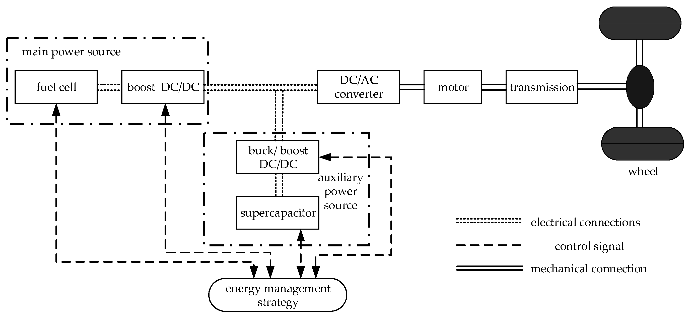
2.1. Powertrain Structure of FCHEV

Figure 1 depicts the structural block diagram of FCHEV. Table 1 shows the major technical characteristics of this paper, which are based on data from the FCHEV in Advisor. A unidirectional DC/DC is coupled to a fuel cell, while a bidirectional DC/DC is connected to a supercapacitor park. These two are then connected in parallel to drive the motor, which finally moves the wheels. Adopting this structure can reduce the requirements of the power bus for the output power, reduce the voltage level of the supercapacitor park terminal and increase the flexibility of controlling the auxiliary power device.

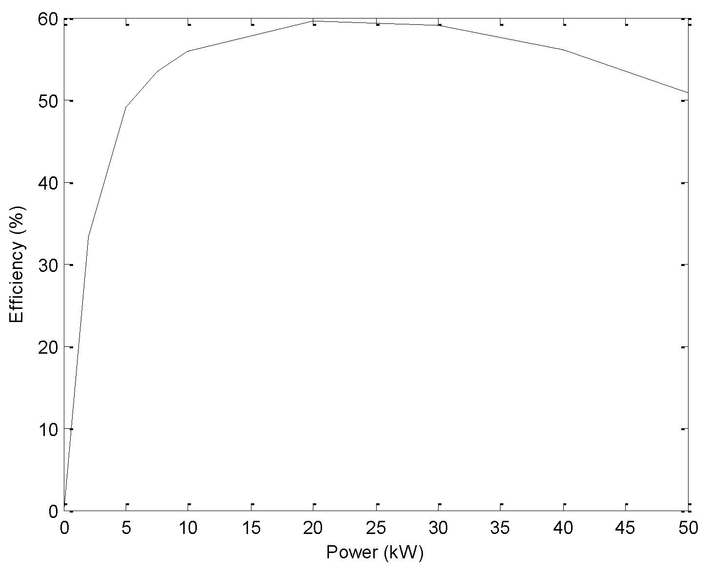
2.2. Fuel Cell Model

FCHEVs use proton exchange membrane fuel cells as their primary source of power. Due to irreversible losses, the output voltage of a PEMFC gradually drops during operation. These irreversible losses are mainly reflected in the polarization overpotential. The fuel cell’s actual output voltage is dependent on the ideal electromotive force and the polarization overpotential, including concentration difference overpotential, ohmic overpotential and activation overpotential, so the output voltage V of the PEMFC monomer is expressed as:
V c e l l = E N e r n s t V a c t V o h m V c o n ,
where E N e r n s t is the ideal electromotive force, V c o n is the concentration difference overpotential, V a c t is the activation overpotential and V o h m is the ohmic overpotential.
The fuel cell stack’s total voltage, as well as the output power, is:
V s = n · V c e l l ,
P f c = I f c · V f c ,
where V s is the fuel cell stack’s total voltage; n is the number of fuel cells.
The power–efficiency curve of the fuel cell is shown in Figure 2. As seen in the graph, the fuel cell works more efficiently when the fuel cell’s output power is in the range of 7 50 kW, so the power in this range is chosen as the high-efficiency zone of the fuel cell.

2.3. Supercapacitor Park Model

As an auxiliary energy source, supercapacitor parks can provide energy to the FCHEV and recover the braking energy from the FCHEV. Considering the operating characteristics of the supercapacitor park, the classical equivalent circuit model is used. The output power of a single supercapacitor park is as follows:
{ P s c = U s c × I s c U s c = E C R s × I s c I s c = I C + I F I C = C d E C d t I F = E C R F ,
where U s c and I s c are the output voltage and current of a single supercapacitor park, respectively; E c is the equivalent capacitor voltage; C is the equivalent capacitor capacity; R S is the charge/discharge resistance; R F is the self-discharge loss resistance; I C and I F are the current value through the equivalent capacitor and self-discharge loss resistance, respectively.
The calculation method of supercapacitor park SOC is as follows:
S O C s c = U s c U s c min U s c max U s c min ,
where U s c min and U s c max are the lowest and highest voltage of the supercapacitor park, respectively.

2.4. DC/DC Model

The fuel cell is connected in series with the unidirectional DC/DC and the supercapacitor pack is connected in series with the bidirectional DC/DC, both of which are connected to the motor controller and supply it with power. Taking into account the effect of DC/DC efficiency, the fuel cell and supercapacitor output power satisfies the following equation.
{ P d 1 = P f c · η d 1 P d 2 = P s c · η d 2 , supercapacitor   park   discharging P d 2 = P s c / η d 2 , supercapacitor   park   charging ,
where η d 2 and η d 1 are the efficiencies of the bidirectional DC/DC converter and the unidirectional DC/DC converter, respectively.

2.5. Motor Model

The motor primarily converts the requested speed and torque into a request for power demand and simultaneously converts the obtained power into the motor’s actual speed and torque. In the driving state, the motor’s power demand is:
T m = ε T max ( n m ) ,
P m e c = T m n m 9550 ,
P eled = P m e c η m ,
where ε is the drive signal provided by the drive model, η m is the motor’s conversion efficiency, T m is the motor’s output torque, T max ( n m ) is the external feature of the motor drive, P eled is the motor’s needed power and P m e c is the motor’s output mechanical power.
The motor power required for braking is similar to that required for driving. The electric motor transforms the vehicle’s mechanical energy into electrical energy stored in the supercapacitor park. The calculation for the electric power created when braking as follows:
P m e c = T m b n m 9550 ,
P eleb = P m e c · η m b ,
where η m is the motor’s conversion efficiency, P eleb is the electrical energy generated during braking and T m b is the motor braking torque.
The motor’s actual torque and output speed are demonstrated in the following equations:
n m = min ( n , n max ) ,
T m = T + I J ,
where, T is the motor drive torque, J is the angular acceleration of the motor and I is the motor’s rotational inertia.

2.6. Complete Vehicle Model

The longitudinal dynamics of the vehicle are modelled based on the dynamics equations of the vehicle in motion, and the forces on the vehicle in motion are obtained by Equation (14):
F t = F r + F a + F g + F j ,
where, F t is the driving force of the vehicle, F r is the rolling resistance of the vehicle, F a is the air resistance, F g is the grade resistance and F j is the acceleration resistance.
{ F r = f m g cos θ , F a = C D A f u a 2 21.15 F g = m g sin θ , F j = δ m d u a d t ,
where, m is the vehicle mass, f is the wheel roll resistance factor, θ is the slope of the driving surface, A f is the windward area, C D is the air resistance factor, u a is the driving speed and δ is the rotating mass conversion factor.
The vehicle driving power balance Equation (17) is obtained from Equation (16):
P t = u a F t η t ,
P t = u a 3600 η t ( f m g + C d A f u a 2 21.15 + m g i s + δ m d u a d t ) ,
where P t is the power required to drive the vehicle, i.e., the demand power, and i s is the current gradient of the road.

3. Energy Management Strategy

3.1. Influencing Factors of Fuel Cell Durability

The following are some driving conditions that affect fuel cell durability:
  • Start–stop condition
A hydrogen/air interface is easily formed when the fuel cell starts and stops, resulting in an interface potential difference, which causes carbon corrosion reaction and water decomposition reaction in this area and accelerates the decay of fuel cell life.
2.
Idling condition
A long idle period can have some damaging effects on a fuel cell. On the one hand, the fuel cell voltage is high, which can result in corrosion of the carbon carrier; on the other hand, platinum aggregates on the catalyst, resulting in a reduction of its activity.
3.
Frequent load changes condition
Fuel cells may experience frequent voltage swings as a consequence of frequent load changes, which reduce their lifetime.
4.
Overload condition
When overloaded, the fuel cell generates large amounts of water, affecting its lifespan.
For this reason, it is necessary to take into account the influence of the above factors on fuel cell durability when designing an energy management strategy.

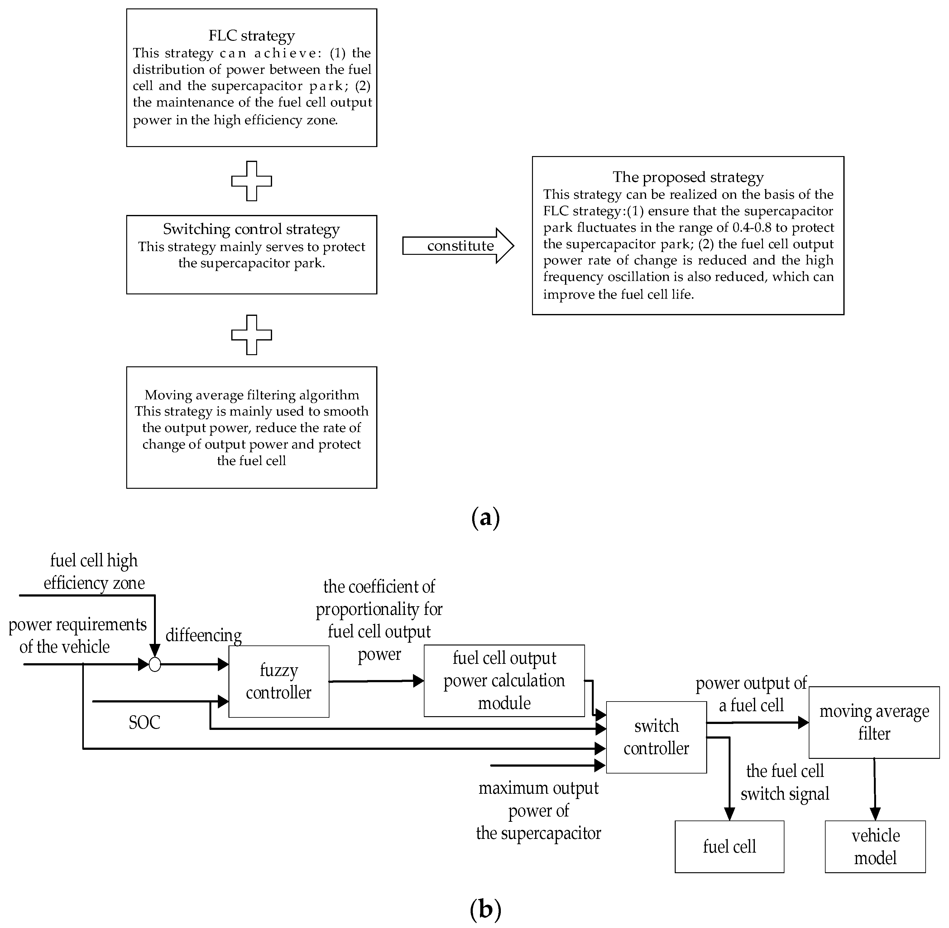
3.2. Design of Compound Energy Management Strategy

The advantage of FLC is that it does not require an accurate model and is robust enough to allocate electricity efficiently to FCHEVs. The typical FLC avoids the frequent starts and stops of the fuel cell, which is good for protecting the fuel cell, but it may cause the supercapacitor park to become overcharged and cause damage to it. Therefore, a switching control strategy was designed to turn off the fuel cell when the SOC of the supercapacitor park exceeds the set upper limit, to ensure that the SOC of the supercapacitor park is kept within a reasonable range. However, as the driving cycle changes, so does the output of the fuel cell. Frequent changes can be detrimental to the fuel cell’s life. Therefore, a moving average filter algorithm is proposed based on the above control method to smooth the fuel cell output power. Figure 3 displays the compound energy management strategy.

3.2.1. Fuzzy Logic Control Strategy

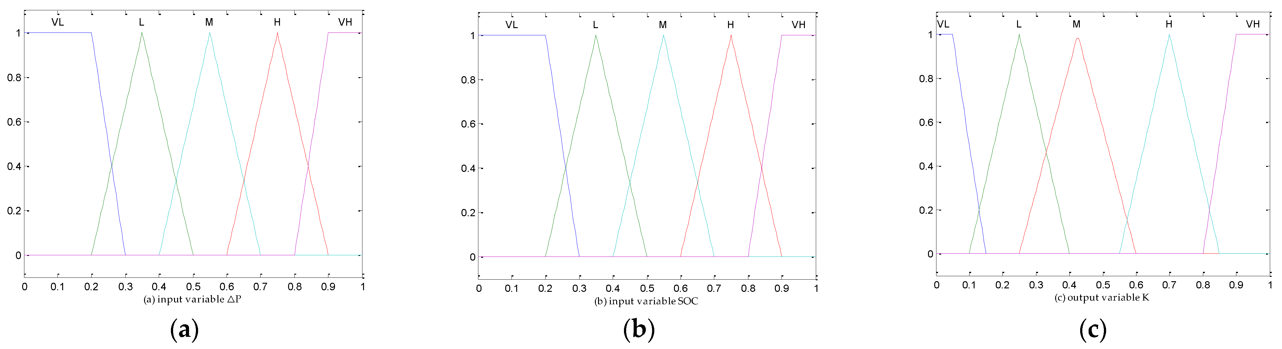
Variable Design for Inputs and Outputs

The input variables are the difference between the vehicle’s demanded power and the lower limit of the fuel cell’s working high-efficiency zone and the supercapacitor park state of charge, and the output variable is the fuel cell’s output power proportional coefficient, K . The fuzzy domain of Δ P is defined as [−10, 60], and SOC and K values are set as [0, 1].

Fuzzy Distribution of Input and Output Variables

The fuzzy subset of Δ P is {VL, L0, L1, M, H0, H1, VH}, the fuzzy subset of supercapacitor park SOC is {VL, L, M, H, VH} and the fuzzy subset of K is {VL, L, M, H, VH}. Figure 4 depicts the membership function.

Formulation of Fuzzy Rules

The output characteristics of fuel cells and supercapacitor parks should be taken into account, together with the required power in the drive cycle. The following principles should be followed when designing the rules:
  • Meet the overall vehicle dynamics requirements: the sum of the fuel cell and supercapacitor park’s output power should be sufficient to fulfill the total vehicle required power of the FCHEV.
  • Meet the economy requirements of FCHEV: to improve the vehicle’s working efficiency, the fuel cell’s output power should be controlled in the high-efficiency zone; simultaneously, the supercapacitor park should also absorb the braking energy as much as possible.
  • Meet the fuel cell’s durability requirements: minimize frequent start–stop situations with fuel cells.
  • Meet the SOC requirements of supercapacitor parks: control the SOC of supercapacitors to fluctuate within a reasonable range (0.4–0.8).
The fuzzy rules designed according to the above principles are shown in Table 2.

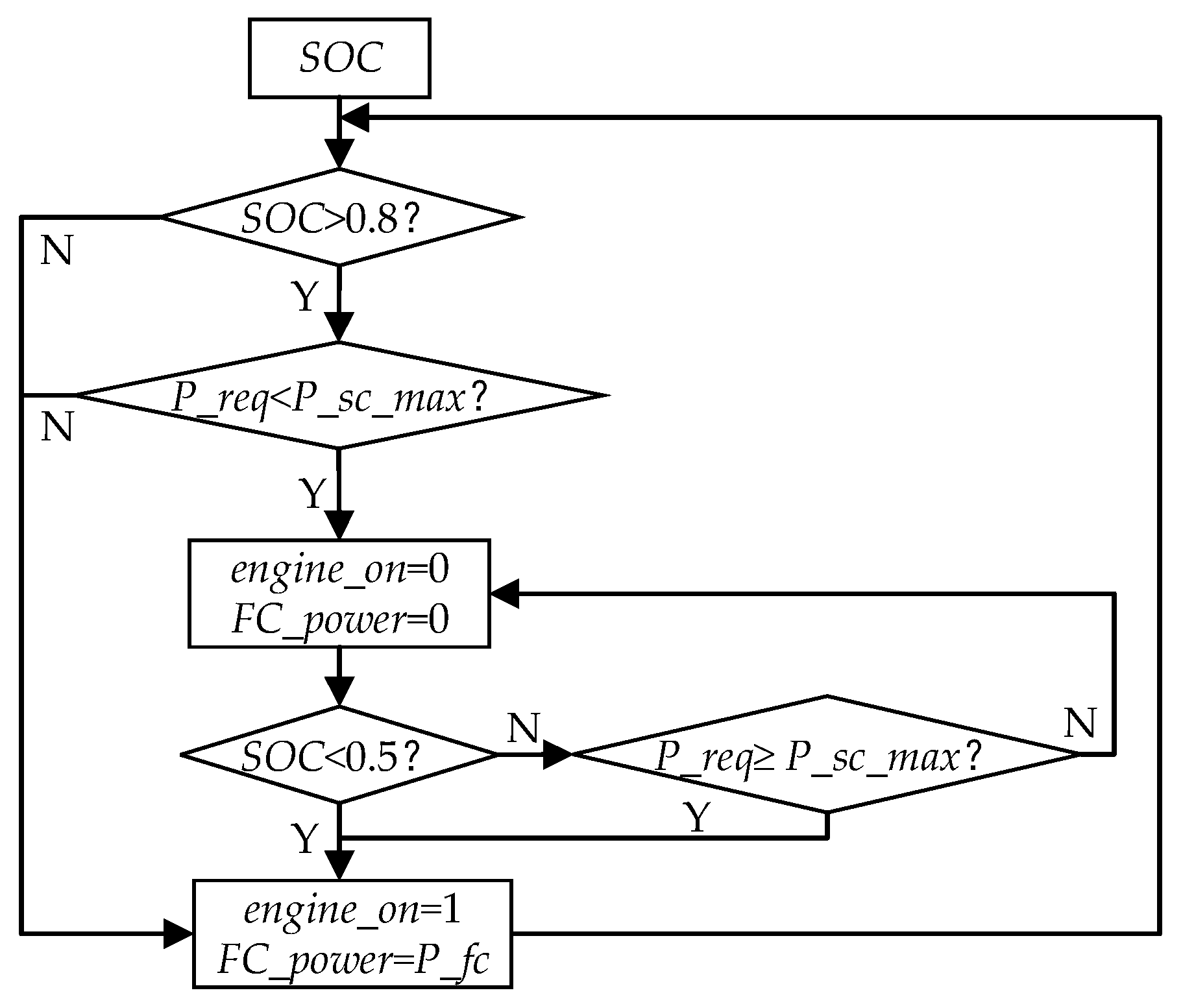
3.2.2. Switching Control Strategy

Using the FLC strategy can keep the fuel cell’s output power in the high-efficiency zone while decreasing the number of fuel cell starts and stops. However, when the whole vehicle’s demand power is less than the fuel cell’s output power for an extended period, the supercapacitor park will take a long time to charge, which can lead to safety accidents. Therefore, a switching control strategy is added to the FLC strategy to solve the above problems.
In Figure 5, the switch control rules can be seen. When the supercapacitor park SOC is greater than the maximum value set for SOC, the fuel cell switches off so that the supercapacitor park starts to discharge, ensuring the safety of the supercapacitor park. Where e n g i n e _ o n is the fuel cell’s start–stop state, 1 is on and 0 is off; P _ r e q is the vehicle’s required power; F C _ p o w e r is the fuel cell’s output power; P _ s c _ m a x is the maximum output power of the supercapacitor park.

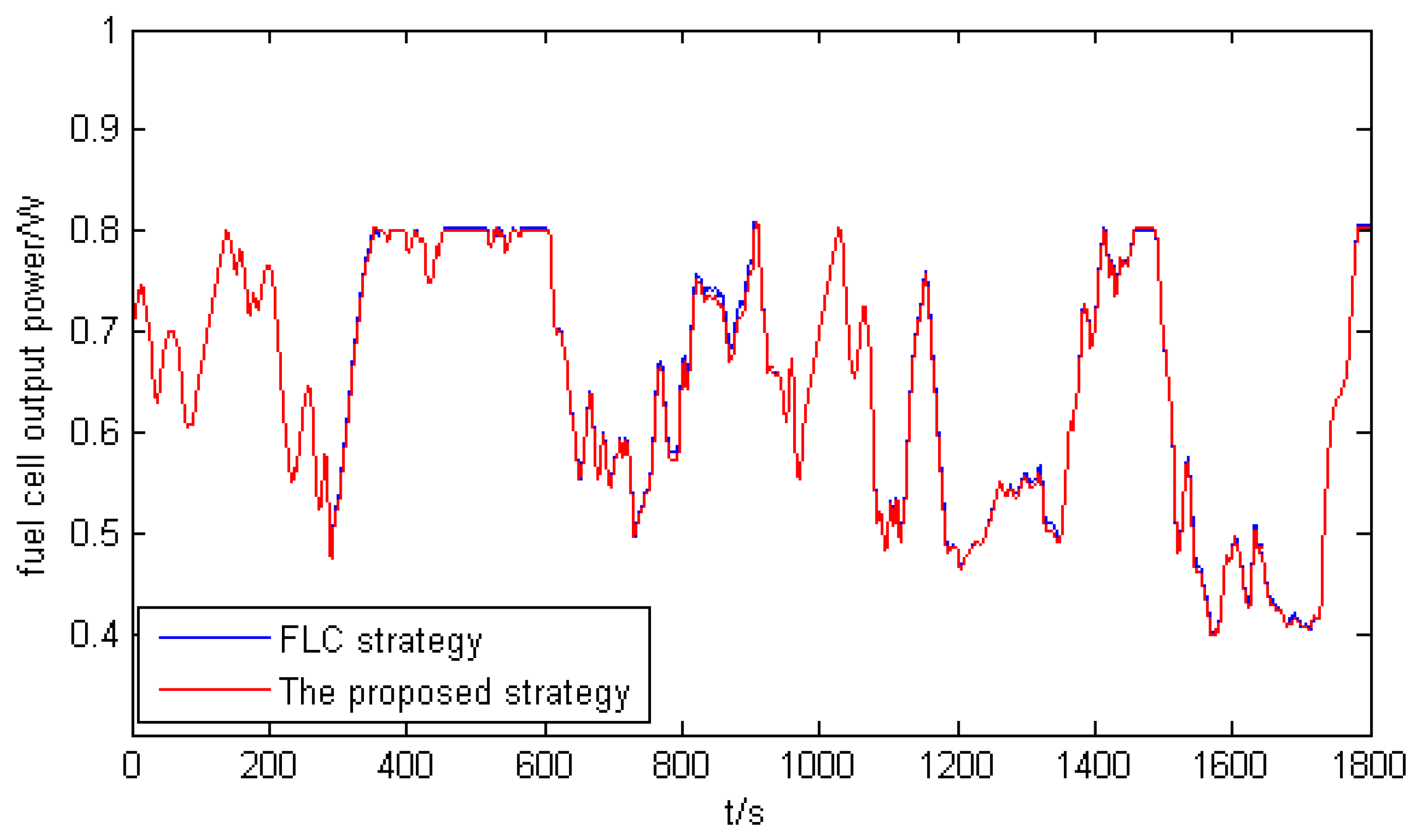
3.2.3. Smoothing Fuel Cell Output Power

The above control method meets the required power of the whole vehicle and reduces the number of starts and stops of the fuel cell. However, the whole vehicle’s required power varies with the driving cycle, affecting the fuel cell’s durability. To further increase the fuel cell’s longevity, a moving average filter method is utilized to minimize the fuel cell’s performance degradation caused by dynamic load variations.
The moving average filtering algorithm considers N consecutive sampled values as a circular queue with a fixed length of N . Whenever new data are collected, they are placed at the tail of the queue, and the data at the head of the original queue are removed (i.e., the principle of first-in, first-out). Each time the filter outputs data, it always outputs the arithmetic mean of the N data in the current queue [25]. The equation is as follows:
P f c = 1 N k = 0 N 1 P [ T k ] ,
where N is the amount of data that the moving window can accommodate in the moving average filtering, k is the moment of the time axis, T is the sampling time, and P [ T k ] is the fuel cell power at the k + 1 sampling point within the moving window.

4. Modeling and Simulation Analysis

4.1. Establishment of Simulation Model

In order to demonstrate the effectiveness of the proposed compound energy management strategy, a joint simulation model of Advisor and Matlab/Simulink was built. Firstly, the Matlab fuzzy logic toolbox was used to design the fuzzy inference system and establish the fuzzy controller; then, the Matlab function was used to program the switching control strategy and the moving average filtering, with the block diagram of the established control strategy shown in Figure 6. Finally, based on the BD_FUELCELL model of the fuel cell hybrid vehicle, the lithium battery was replaced with a supercapacitor park. In order to combine the designed control strategy with the complete vehicle model, a secondary development of the Advisor is carried out, in the following steps.
  • Modify the module control library: open the Advisor control module database, save the original <vc>fuel cell as <vc>fuel cell_new, and finally embed the designed control strategy into <vc>fuel cell_new to complete the control module modification.
  • Modify the top-level module: open the original Advisor top-level module BD_FUELCELL.mdl and save it as BD_FUELCELL_new.mdl, replace <vc>fuel cell in this module with <vc>fuel cell _new.
  • Modify the m file: first save the original FUELCELL_defaults_in.m as FUECELL_new_defaults_in.m and modify the first two sentences of the file to the top-level module of your own name; then, to make the module recognizable to the Advisor, add the following statement to the driver chain field of the global variable Vinf:
optionlist (‘add’,’drivetrain’,’ FUECELL_new’).
Finally, add the following statement to the block_diagram_name.m file:
case ‘FUECELL_new’
bd_name = ‘BD_ FUECELL_new’.
In this way, the designed control strategy is embedded into the Advisor.

4.2. Simulation Comparison and Analysis

In order to verify the feasibility and superiority of the proposed compound energy management strategy, the proposed compound energy management strategy was compared and analyzed with typical FLC strategies, PI control and power-following strategies. The PI regulator ( K p = 2500 ,   K i = 250 ) is used to control the SOC of the supercapacitor park, and the power of the supercapacitor park is adjusted according to the value of the SOC, so the output of the PI regulator is the power of the supercapacitor park, and then is removed from the whole vehicle demand to obtain the output power of the fuel cell. In the power-following control strategy, the fuel cell output power is controlled based on the power required by the whole vehicle and adjusted by the equilibrium power obtained with the supercapacitor park SOC value as the independent variable. When the vehicle is in braking mode, the fuel cell maintains a constant power output and the supercapacitor park recovers the braking energy and captures the fuel cell output; when the vehicle is in drive, the fuel cell output power increases when the supercapacitor park SOC decreases and the fuel cell output power decreases when the supercapacitor park SOC increases.
For this paper, we selected a typical driving cycle WLTC for simulation and analysis, which lasted for 1800 s and was divided into four parts: low speed, medium speed, high speed and super high speed. The WLTC speed following curve is shown in Figure 7. From the figure, it can be seen that each control strategy can complete the speed following of WLTC, indicating that each control strategy can meet the power demand of the whole vehicle, which verifies the effectiveness of the energy management strategy.
The proposed compound energy management strategy and the typical FLC strategy of the supercapacitor park SOC variation comparison curve are shown in Figure 8. According to the characteristics of the supercapacitor park, its SOC is generally allowed to fluctuate in the range of 0.2–0.8 when the vehicle is running [26]. The initial SOC of the supercapacitor park is 0.7 before operation, but as the WLTC condition is constantly changing in acceleration and deceleration, the supercapacitor park will have frequent charging and discharging, and its SOC will also fluctuate frequently. As can be seen from the figure, during the whole operation period, the average value of supercapacitor park SOC under the proposed strategy control is lower than that of the FLC, which indicates that the supercapacitor park outputs more energy, reduces the fuel cell output power share and reduces the fluctuation of fuel cell output power with the change of operating conditions, i.e., the fluctuation of power demand caused by the change of operating conditions is borne by the supercapacitor park with long life, which is conducive to improving the durability of the fuel cell. The SOC value also remains within a preset range (i.e., 0.4 to 0.8).
The simulation comparison results of fuel cell output power under the proposed strategy and FLC strategy are shown in Figure 9. As can be seen from the figure, the hydrogen consumption per 100 km for the FLC strategy is 45.4   L · km 1 and the hydrogen consumption per 100 km for the proposed strategy is 45.5   L · km 1 . Overall, both strategies have good fuel economy, but the output power of the fuel cell based on fuzzy control is not smooth enough, and occasionally high frequency oscillations occur, which is not conducive to the durability of the fuel cell; with the proposed strategy, the frequency of fluctuations in the output power of the fuel cell decreases around 840 s, 1227 s, 1250 s and 1550 s, and changes more smoothly, allowing the fuel cell to operate more smoothly within a driving cycle. Thus, the strategy is conducive to improving the durability of the fuel cell.
The simulation results of the fuel cell output power under the proposed strategy, PI control and power-following control are shown in Figure 10 and Table 3. As can be seen from the graphs and tables, the output power of the fuel cell based on PI control changes frequently, with the hydrogen consumption per 100 km reaching 52.39   L · km 1 and the start–stop situation occurring constantly, which adversely affects the durability of the fuel cell. The power-following control strategy results in six start–stops and large variations in fuel cell output power within one driving cycle, resulting in large fluctuations in efficiency. Finally, the hydrogen consumption per 100 km reaches 50.1   L · km 1 , while the proposed compound energy management strategy has only four start–stops and relatively smooth and less frequent fluctuations in output power, effectively reducing the impact of frequent start–stops on fuel cell life, improving fuel cell durability, reducing hydrogen consumption per 100 km by 13.15% and 9.18%, respectively, and increasing fuel cell efficiency by 1.8% and 3.7%, respectively.

5. Conclusions

The energy management of electric vehicles using a hybrid of fuel cells and supercapacitor parks was studied. Aiming at the economy of the whole vehicle and the durability of fuel cells, a composite energy management strategy is proposed on the basis of conventional fuzzy control. The co-simulation analyses were carried out, and the following conclusions were drawn:
  • All control strategies can meet the power requirements of the whole vehicle, but the proposed compound energy management strategy ensures that the supercapacitor park SOC fluctuates within a reasonable range on the basis of the advantages of conventional fuzzy control, and effectively avoids the overcharge of the supercapacitor park, to protect the supercapacitor park.
  • The proposed compound energy management strategy smooths the output power of the fuel cell through the moving average filtering algorithm, which improves the smoothness of the output power of the fuel cell, reduces the rate of change of the power of the fuel cell and improves the durability of the fuel cell.
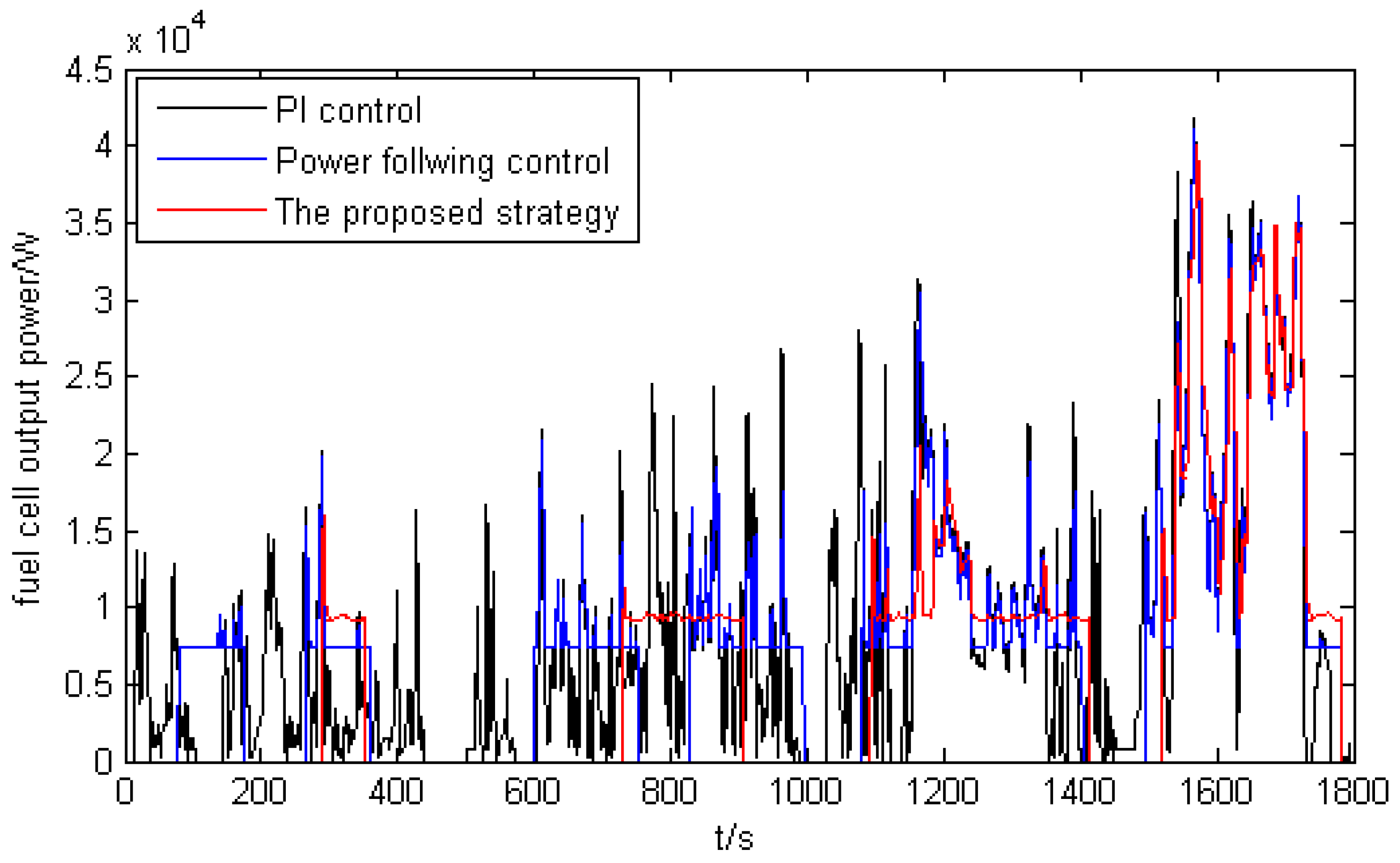
  • Compared with the PI control and power-following control strategy, the compound energy management strategy reduces the number of starts and stops of the fuel cell and effectively avoids the reduction of the life of the fuel cell.
  • The compound energy management strategy can fully consider the operating states of the fuel cell and supercapacitor park, which can effectively utilize the high power density of the supercapacitor park to ensure a smooth fuel cell output power while effectively improving the economy of the fuel cell hybrid vehicle. Compared with the PI control and power-following control strategy, the equivalent hydrogen consumption per 100 km under the compound energy management strategy is reduced by 13.15% and 9.18%, respectively, and the number of starts and stops is also reduced by 11 and 2 times, respectively. Therefore, this strategy can effectively reduce the hydrogen consumption of FCHEV and improve the durability of the fuel cell.

Author Contributions

Conceptualization, C.L. and W.L.; methodology, C.L. and W.L.; software, C.L.; validation, C.L.; formal analysis, C.L.; investigation, C.L.; data curation, C.L.; writing—original draft preparation, C.L.; writing—review and editing, C.L., W.L., H.L. and C.H.; supervision, W.L., H.L. and C.H. All authors have read and agreed to the published version of the manuscript.

Funding

This research was funded by the Natural Science Foundation of Guangxi, grant number 2020GXNSFDA238011; the Open Fund Project of Guangxi Key Laboratory of Automatic Detection Technology and Instruments, grant number YQ21203; and the Independent Research Project of Guangxi Key Laboratory of Auto Parts and Vehicle Technology, grant number 2020GKLACVTZZ02.

Institutional Review Board Statement

Not applicable.

Informed Consent Statement

Not applicable.

Data Availability Statement

The data used in this paper, such as the vehicle parameters, are stated in the paper and no other data are available.

Conflicts of Interest

The authors declare no conflict of interest.

References

  1. Zhu, D.B.; Wang, X.Y.; Li, Y.W. Progress on energy management strategies for hybrid electric vehicles. Mach. Des. Manuf. 2020, 293–296. [Google Scholar] [CrossRef]
  2. Liu, Y.D.; Guo, H.X.; Ouyang, X.P. Development status and future prospects of hydrogen fuel cell technology. Strateg. Study CAE 2021, 23, 162–171. [Google Scholar] [CrossRef]
  3. Shao, Z.G.; Yi, B.L. Developing trend and present status of hydrogen energy and fuel cell development. Bull. Chin. Acad. Sci. 2019, 34, 469–477. [Google Scholar]
  4. Han, L. Research on optimal power distribution strategy of vehicle hybrid energy storage power system. Foreign Electron. Meas. Technol. 2020, 39, 94–98. [Google Scholar]
  5. Cui, P.F.; Shen, Y.; Zhao, K.Y. Energy management for fuel cell vehicle power system based on fuzzy control. Mach. Build. Autom. 2020, 49, 177–179, 187. [Google Scholar]
  6. Li, D.X.; Xu, B.; Jie, T.; Ma, Z. Energy management strategy for fuel cell and battery hybrid vehicle based on fuzzy logic. Processes 2020, 8, 882. [Google Scholar] [CrossRef]
  7. Siab, S.; Hamouda, Z.; Marouani, K. Energy Management in a Fuel Cell Hybrid Electric Vehicle Using a Fuzzy Logic Approach. In Proceedings of the 2017 5th International Conference on Electrical Engineering, Boumerdes, Algeria, 29–31 October 2017. [Google Scholar]
  8. Wang, Q.; Li, D.G.; Miao, H.C. Research on energy management strategy of fuel cell vehicle based on fuzzy logic control. Automot. Eng. 2019, 41, 1347–1355. [Google Scholar]
  9. Zhang, G.R.; Chen, W.R.; Li, Q. Modeling, optimization and control of a FC/battery hybrid locomotive based on ADVISOR. Int. J. Hydrogen Energy 2017, 42, 18568–18583. [Google Scholar] [CrossRef]
  10. Chen, J.; Xu, C.F.; Wu, C.S. Adaptive fuzzy logic control of fuel-cell-battery hybrid systems for electric vehicles. IEEE Trans. Ind. Inform. 2018, 14, 292–300. [Google Scholar] [CrossRef]
  11. Lv, X.Q.; Wu, Y.B.; Lian, J. Energy management of hybrid electric vehicles: A review of energy optimization of fuel cell hybrid power system based on genetic algorithm. Energy Convers. Manag. 2020, 205, 112474. [Google Scholar]
  12. Ahmadi, S.; Bthaee, S.M.T.; Hosseinpour, A.H. Improving fuel economy and performance of a fuel-cell hybrid electric vehicle (fuel-cell, battery, and ultra-capacitor) using optimized energy management strategy. Energy Convers. Manag. 2018, 160, 74–84. [Google Scholar] [CrossRef]
  13. Munoz, P.M.; Correa, G.; Gaudiano, M.E.; Fernandez, D. Energy management control design for fuel cell hybrid electric vehicles using neural networks. Int. J. Hydrogen Energy 2017, 42, 28932–28944. [Google Scholar] [CrossRef]
  14. Chen, H.; Chen, J.; Lu, H.; Yan, C.; Liu, Z. A modified MPC-based optimal strategy of power management for fuel cell hybrid vehicles. IEEE/ASME Trans. Mechatron. 2020, 25, 2009–2018. [Google Scholar] [CrossRef]
  15. Shi, J.W.; Xie, J.F.; Zhao, Y. Research on durability control strategy of vehicle fuel cell. Mod. Manuf. Eng. 2021, 56–63. [Google Scholar] [CrossRef]
  16. Li, Q.; Chen, W.; Liu, Z.; Li, M.; Ma, L. Development of energy management system based on a power sharing strategy for a fuel cell-battery-supercapacitor hybrid tramway. J. Power Sources 2015, 279, 267–280. [Google Scholar] [CrossRef]
  17. Flosescu, A.; Bacha, S.; Munteanu, I.; Bratcu, A.I.; Rumeau, A. Adaptive frequency-separation-based energy management system for electric vehicles. J. Power Sources 2015, 280, 410–421. [Google Scholar] [CrossRef]
  18. Wang, Z.; Xie, Y.; Sun, W.; Zang, P. Modeling and energy management strategy research of fuel cell bus. J. Tongji Univ. (Nat. Sci.) 2019, 47, 97–103, 123. [Google Scholar]
  19. Xu, L.; Mueller, C.D.; Li, J. Multi-objective component sizing based on optimal energy management strategy of fuel cell electric vehicles. Appl. Energy 2015, 157, 664–674. [Google Scholar] [CrossRef]
  20. Lin, X.Y.; Xia, Y.T.; Li, X.F.; Lin, H.B. Equivalent consumption minimization strategy adaptive to various driving ranges for fuel cell. Automot. Eng. 2019, 41, 750–756. [Google Scholar]
  21. Yan, Z.F.; Wang, H.L.; Wu, J.L.; Zhang, N. Modeling and energy management strategy optimization for the drive system of a fuel cell based bus. J. Chongqing Univ. Technol. (Nat. Sci.) 2021, 35, 8–16. [Google Scholar]
  22. Zhao, Z.; Wang, T.; Li, M.; Wang, H.; Wang, Y.Q. Optimization of fuzzy control energy management strategy for fuel cell vehicle power system using a multi-slandgenetic algorithm. Energy Sci. Eng. 2020, 9, 548–564. [Google Scholar] [CrossRef]
  23. Zhou, J.H.; Gu, C.; Liu, J.; Hai, B.; Sai, Y.H. Energy management strategy of a fuel cell hybrid electric vehicle based on fuzzy logic and improved IGWO. J. Chongqing Univ. Technol. (Nat. Sci.) 2021, 35, 33–41. [Google Scholar]
  24. Liu, Q.; Zhan, Y.D.; Li, R.Q. Research on a multiobjective optimization energy management strategy for fuel cell electric vehicles. Electron. Meas. Technol. 2020, 43, 31–36. [Google Scholar]
  25. Li, Z.H.; Fu, Z.M.; Tao, F.Z. Hierarchical energy management strategy of fuel cell hybrid electrical vehicle. Fire Control. Command. Control. 2019, 44, 113–118. [Google Scholar]
  26. Chan, C.C.; Bouscayrol, A.; Chen, K. Electric, hybrid, and fuel-cell vehicles: Architectures and modeling. IEEE Trans. Veh. Technol. 2010, 59, 589–598. [Google Scholar] [CrossRef]
Figure 1. Powertrain structure of FCHEV.
Energies 15 01721 g001
Figure 2. Power–efficiency curve for the fuel cell.
Energies 15 01721 g002
Figure 3. Compound energy management strategy. (a) Composition diagram; (b) simulation structure diagram.
Energies 15 01721 g003
Figure 4. Membership function. (a) Input variable Δ P ; (b) input variable SOC; (c) output variable K .
Energies 15 01721 g004
Figure 5. Switch control rules.
Energies 15 01721 g005
Figure 6. Compound energy management control.
Energies 15 01721 g006
Figure 7. WLTC speed following curve.
Energies 15 01721 g007
Figure 8. Variation curve of SOC.
Energies 15 01721 g008
Figure 9. Output power comparison between fuzzy control and compound energy management.
Energies 15 01721 g009
Figure 10. Output power comparison between PI control, power following and compound energy management.
Energies 15 01721 g010
Table 1. The vehicle’s primary technical parameters.
NameParameterValueUnit
vehicle partmass1138 m / kg
drag coefficient0.335 C D
frontal area2 A f / m 2
wheelwheel radius0.282 r / m
rolling coefficient0.009 f
drive motorpower max75 kW
max efficiency0.92-
fuel cellpower max50 kW
max efficiency0.6-
supercapacitor parkrated voltage2 V
group number80-
capacity2.1 A · h
Table 2. Fuzzy rules.
K Δ P
VLL0L1MH0H1VH
SOCVLMHVHVHVHVHVH
LMMMHHVHVH
MVLVLVLMMHH
HVLVLVLLLLM
VHVLVLVLVLVLVLVL
Table 3. Comparison of simulation results of three energy management strategies.
Statistical ResultsPI ControlPower Following Control StrategyCompound Energy Management Strategy
equivalent   hydrogen   consumption   per   hundred   kilometers   ( L · 100   km 1 ) 52.3950.145.5
start and stop times1564
fuel cell efficiency0.540.530.55
supercapacitor park efficiency0.970.980.98
Publisher’s Note: MDPI stays neutral with regard to jurisdictional claims in published maps and institutional affiliations.

