
Numerical Analysis of Wick-Type Two-Phase Mechanically Pumped Fluid Loop for Thermal Control of Electric Aircraft Motors


Abstract
:
1. Introduction
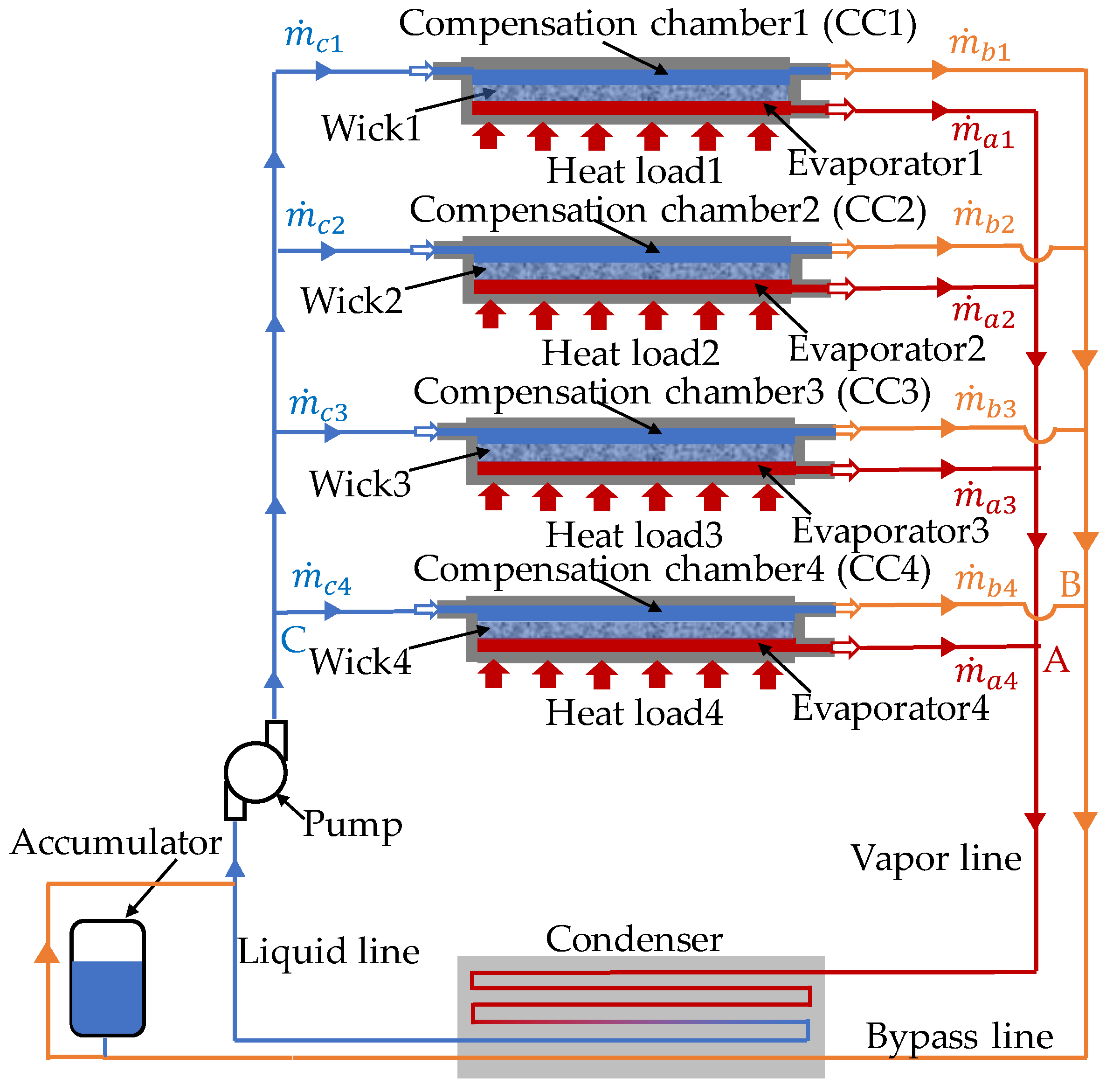
2. Wick-Type Two-Phase Mechanically Pumped Fluid loop
2.1. Operating Characteristics
2.2. Design Method
3. Numerical Model
3.1. Modeling System
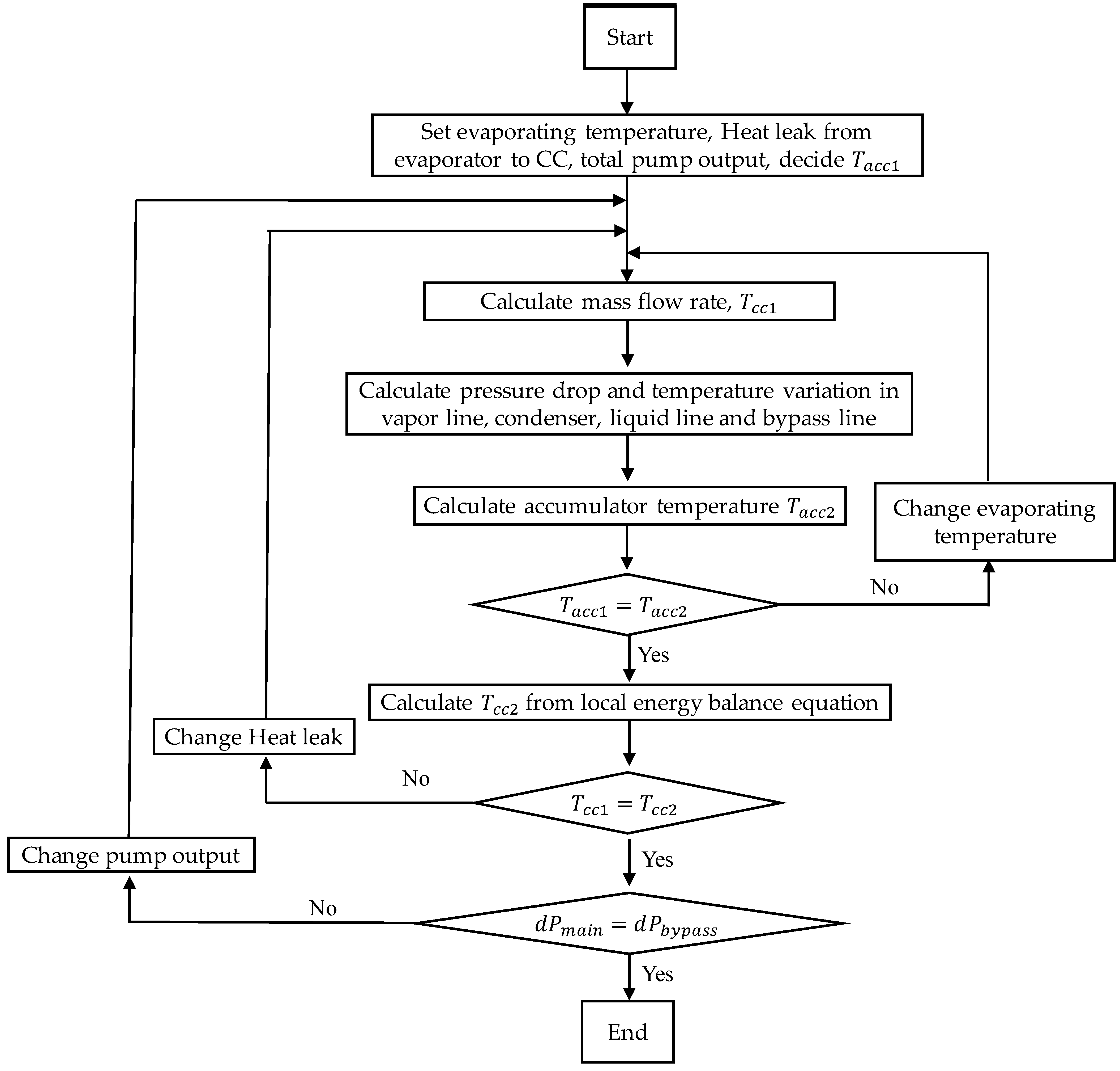
3.2. Calculation Procedure
3.3. Calculation Conditions
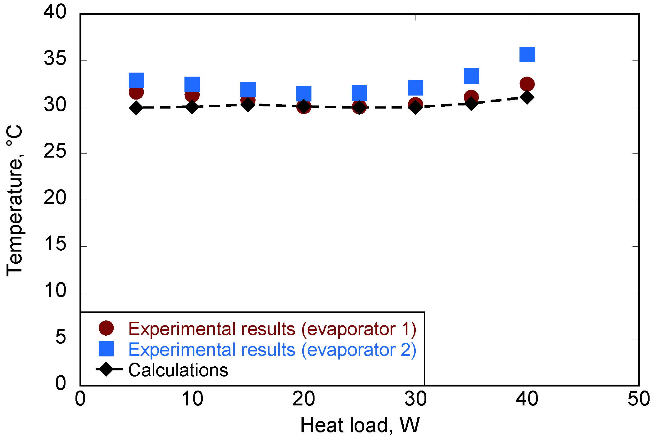
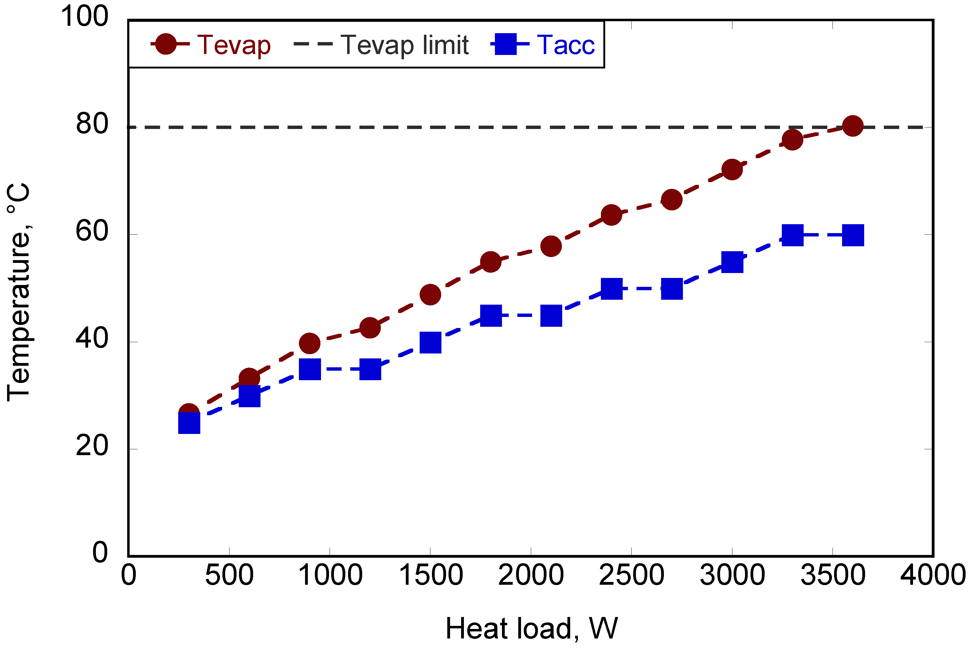
4. Calculation Results
5. Conclusions
Author Contributions
Funding
Institutional Review Board Statement
Informed Consent Statement
Data Availability Statement
Conflicts of Interest
Nomenclature
| Cross-sectional area of the wick, (m2) | |
| Parameter for calculation, (-) | |
| Parameter for calculation, (-) | |
| Parameter for calculation, (-) | |
| Parameter for calculation, (-) | |
| Specific heat, (J·kg−1·K−1) | |
| Inner diameter, (m) | |
| Distance, (m) | |
| Pressure drop, (Pa) | |
| Gradient of the pressure drop assuming that the entire working fluid is in the liquid phase, (Pa·m−1) | |
| Gradient of the pressure drop assuming that the entire working fluid is in the vapor phase, (Pa·m−1) | |
| Gradient of the two-phase flow pressure drop, (Pa·m−1) | |
| Gradient of the pressure drop, (Pa·K−1) | |
| Pressure drop in the whole loop, (Pa) | |
| Temperature variation, (K) | |
| Thickness of the wick, (m) | |
| Darcy friction factor, (-) | |
| Parameter for calculation, (Pa·m−1) | |
| Galilei number, (-) | |
| Gravitational acceleration, (m·s−2) | |
| Thermal conductance between evaporator case and evaporating surface, (W·K−1) | |
| Thermal conductance between working fluid and surroundings, (W·K−1) | |
| Thermal conductance of wick, (W·K−1) | |
| Heat transfer coefficient, (W·m−2·K−1) | |
| Condensation number, (-) | |
| Thermal conductivity of air, (W·m−1·K−1) | |
| Thermal conductivity of wick, (W·m−1·K−1) | |
| Mass flow rate, (kg·s−1) | |
| Mass flow rate in the main flow path of evaporator 1, (kg·s−1) | |
| Mass flow rate in the main flow path of evaporator 2, (kg·s−1) | |
| Mass flow rate in the main flow path of evaporator 3, (kg·s−1) | |
| Mass flow rate in the main flow path of evaporator 4, (kg·s−1) | |
| Mass flow rate in the bypass flow path of evaporator 1, (kg·s−1) | |
| Mass flow rate in the bypass flow path of evaporator 2, (kg·s−1) | |
| Mass flow rate in the bypass flow path of evaporator 3, (kg·s−1) | |
| Mass flow rate in the bypass flow path of evaporator 4, (kg·s−1) | |
| Mass flow rate of the returning liquid to CC 1, (kg·s−1) | |
| Mass flow rate of the returning liquid to CC 2, (kg·s−1) | |
| Mass flow rate of the returning liquid to CC 3, (kg·s−1) | |
| Mass flow rate of the returning liquid to CC 4, (kg·s−1) | |
| Mass flow rate of liquid, (kg·s−1) | |
| Nusselt number in the forced convection condensation region, (-) | |
| Nusselt number from the co-existing forced and natural convection condensation region to the end of the natural convection condensation region, (-) | |
| Pressure of accumulator, (Pa) | |
| Pressure of condenser, (Pa) | |
| Prandtl number, (-) | |
| Prandtl number of liquid, (-) | |
| Heat exchange amount from CC to surroundings, (W) | |
| Heat exchange amount from evaporator to surroundings, (W) | |
| Heat load, (W) | |
| Reynolds number of liquid, (-) | |
| Temperature of surroundings, (K) | |
| Temperature of accumulator, (K) | |
| Temperature of compensation chamber, (K) | |
| Temperature of condenser, (K) | |
| Temperature of heating surface, (K) | |
| Temperature of evaporating surface, (K) | |
| Temperature of working fluid, (K) | |
| Temperature of liquid line outlet, (K) | |
| Temperature of wing, (K) | |
| Velocity, (m·s−1) | |
| Flight speed, (m·s−1) | |
| Vapor quality, (-) | |
| Parameter for calculation, (-) | |
| Latent heat, (J·kg−1) | |
| Density, (kg·m−3) | |
| Density of liquid, (kg·m−3) | |
| Density of vapor, (kg·m−3) | |
| Viscosity, (Pa·s) | |
| Viscosity of air, (m2·s−1) | |
| Viscosity of liquid, (m2·s−1) |
References
- Nishizawa, A.; Kobayashi, H.; Iijima, T.; Yamazaki, K.; Okuyama, M.; Tagashira, T.; Hirano, Y.; Yoshimura, A.; Shindo, S.; Okai, K. Flight Demonstration of Electric Propulsion System Technology for Aircraft Application. Aeronaut. Space Sci. Jpn. 2017, 65, 196–200. [Google Scholar]
- Bacchini, A.; Cestino, E. Electric VTOL Configurations Comparison. Aerospace 2019, 6, 26. [Google Scholar] [CrossRef] [Green Version]
- Montagnani, D.; Tugnoli, M.; Fonte, F.; Zanotti, A.; Syal, M.; Droandi, G. Mid-fidelity analysis of unsteady interactional aerodynamics of complex VTOL configurations. In Proceedings of the 45th European Rotorcraft Forum, Warsaw, Poland, 17–20 September 2019. [Google Scholar]
- Hall, D.L.; Chin, J.C.; Anderson, A.D.; Thompson, J.T.; Smith, A.D.; Edwards, R.D.; Duffy, K.P. Development of a Maxwell X-57 high lift motor reference design. In Proceedings of the AIAA Propulsion and Energy 2019 Forum, Indianapolis, IN, USA, 19–22 August 2019. [Google Scholar]
- Bradley, M.K.; Droney, C.K. Subsonic Ultra Green Aircraft Research: Phase II—Volume II—Hybrid Electric Design Exploration; NASA/CR–2015-218704/Volume II; Boeing Research and Technology: Huntington Beach, CA, USA, 2019. [Google Scholar]
- Kratz, J.L.; Thomas, G.L. Dynamic analysis of the STARC-ABL propulsion system. In Proceedings of the AIAA Propulsion and Energy 2019 Forum, Indianapolis, IN, USA, 19–22 August 2019. [Google Scholar]
- Loder, D.C.; Bollman, A.; Armstrong, M.J. Turbo-electric Distributed Aircraft Propulsion: Microgrid Architecture and Evaluation for ECO-150. In Proceedings of the 2018 IEEE Transportation Electrification Conference and Expo, Long Beach, CA, USA, 13–15 June 2018. [Google Scholar]
- Berton, J.J.; Haller, W.J. A noise and emissions assessment of the N3-X transport. In Proceedings of the 52nd Aerospace Sciences Meeting, National Harbor, MD, USA, 13–17 January 2014. [Google Scholar]
- IATA Technology Roadmap, 4th ed.; International Air Transport Association (IATA): Montreal, Canada, 2013.
- Freeman, J.; Osterkamp, P.; Green, M.; Gibson, A.; Schiltgen, B. Challenges and Opportunities for Electric Aircraft Thermal Management. Aircr. Eng. Aerosp. Technol. Int. J. 2014, 86, 519–524. [Google Scholar] [CrossRef]
- Schiltgen, B.T.; Freeman, J. Aeropropulsive interaction and thermal system integration within the ECO-150: A turboelectric distributed propulsion airliner with conventional electric machines. In Proceedings of the 16th AIAA Aviation Technology, Integration, and Operations Conference, Washington, DC, USA, 13–17 June 2016. [Google Scholar]
- Vrable, D.L.; Yerkes, K.L. A Thermal Management Concept for More Electric Aircraft Power System Applications. SAE Trans. Sect. J. Aerosp. 1998, 107, 181–186. [Google Scholar]
- Annapragada, S.R.; Macdonald, M.; Sur, A.; Mahmoudi, R.; Lents, C. Hybrid Electric Aircraft Battery Heat Acquisition System. In Proceedings of the 2018 AIAA/IEEE Electric Aircraft Technologies Symposium, Cincinnati, OH, USA, 9–11 July 2018. [Google Scholar]
- Deisenroth, D.C.; Ohadi, M. Thermal Management of High-Power Density Electric Motors for Electrification of Aviation and Beyond. Energies 2019, 12, 3594. [Google Scholar] [CrossRef] [Green Version]
- Ku, J. Operating characteristics of loop heat pipes. In Proceedings of the 29th International Conference on Environmental Systems, Denver, CO, USA, 12–15 July 1999. [Google Scholar]
- Maydanik, Y.F. Loop heat pipes. Appl. Therm. Eng. 2005, 25, 635–657. [Google Scholar] [CrossRef]
- Grob, E.; Baker, C.; McCarthy, T. Geoscience laser altimeter system (Glas) loop heat pipes-an eventful first year on orbit. In Proceedings of the 34th International Conference on Environmental Systems, Colorado Springs, CO, USA, 19–22 July 2004. [Google Scholar]
- Fukushima, K.; Nagano, H. New evaporator structure for micro loop heat pipes. Int. J. Heat Mass Transf. 2017, 106, 1327–1334. [Google Scholar] [CrossRef]
- Pastukhov, V.G.; Maydanik, Y.F. Active coolers based on copper-water LHPs for desktop PC. Appl. Therm. Eng. 2009, 29, 3140–3143. [Google Scholar] [CrossRef]
- Bhandari, P.; Birur, G.; Bame, D.; Mastropietro, A.J.; Miller, J.; Karlmann, P.; Liu, Y.; Anderson, K. Performance of the mechanically pumped fluid loop rover heat rejection system used for thermal control of the Mars science laboratory curiosity rover on the surface of Mars. In Proceedings of the 43rd International Conference on Environmental Systems, Vail, CO, USA, 14–18 July 2013. [Google Scholar]
- Daimaru, T.; Furst, B.; Cappucci, S.; Sunada, E.; Birur, G. Development of an evaporator using porous wick structure for a two-phase mechanically pumped fluid loop. In Proceedings of the 49th International Conference On Environmental Systems, Boston, MA, USA, 7–11 July 2019. [Google Scholar]
- Kawasaki, H.; Fujii, K. Ground test loop for interfacial behaviors and heat transfer characteristics in boiling two phase flow (JEM-TPF). In Proceedings of the 41st International Conference on Environmental Systems, Portland, OR, USA, 17–21 July 2011. [Google Scholar]
- Ohta, H.; Asano, H.; Kawanami, O.; Suzuki, K.; Imai, R.; Shinmoto, Y.; Matsumoto, S.; Kurimoto, T.; Takaoka, H.; Fujii, K.; et al. Development of boiling and two-phase flow experiments on board ISS (Research Objectives and Concept of Experimental Setup). Int. J. Microgravity Sci. Appl. 2016, 33, 330102. [Google Scholar]
- Imai, R.; Suzuki, K.; Kawasaki, H.; Ohta, H.; Shinmoto, Y.; Asano, H.; Kawanami, O.; Fujii, K.; Matsumoto, S.; Kurimoto, T.; et al. Development of Boiling and Two-phase Flow Experiments on Board ISS (Condensation section). Int. J. Microgravity Sci. Appl. 2016, 33, 330103. [Google Scholar]
- Gomyo, T.; Asano, H.; Ohta, H.; Shinmoto, Y.; Kawanami, O.; Suzuki, K.; Imai, R.; Oka, T.; Tomobe, T.; Usuku, K.; et al. Development of Boiling and Two-phase Flow Experiments on Board ISS (Void Fraction Characteristics in the Observation Section just at the Downstream of the Heating Section). Int. J. Microgravity Sci. Appl. 2016, 33, 330104. [Google Scholar]
- Hirokawa, T.; Yamamoto, D.; Yamamoto, D.; Shinmoto, Y.; Ohta, H.; Asano, H.; Kawanami, O.; Suzuki, K.; Imai, R.; Takayanagi, M.; et al. Development of Boiling and Two-phase Flow Experiments on Board ISS (Investigation on Performance of Ground Model). Int. J. Microgravity Sci. Appl. 2016, 33, 330105. [Google Scholar]
- Sawada, K.; Kurimoto, T.; Okamoto, A.; Matsumoto, S.; Takaoka, H.; Kawasaki, H.; Takayanagi, M.; Shinmoto, Y.; Asano, H.; Kawanami, O.; et al. Development of Boiling and Two-phase Flow Experiments on Board ISS (Dissolved Air Effects on Subcooled Flow Boiling Characteristics). Int. J. Microgravity Sci. Appl. 2016, 33, 330106. [Google Scholar]
- Okubo, M.; Kawanami, O.; Nakamoto, K.; Asano, H.; Ohta, H.; Shinmoto, Y.; Suzuki, K.; Imai, R.; Matsumoto, S.; Kurimoto, T.; et al. Development of Boiling and Two-phase Flow Experiments on Board ISS (Temperature Data Derivation and Image Analysis of a Transparent Heated Short Tube in the Glass Heated Section). Int. J. Microgravity Sci. Appl. 2016, 33, 330107. [Google Scholar]
- Schweizer, N.; Stephan, P.; Schlitt, R. A concept for a miniature, mechanically pumped two-phase cooling loop. In Proceedings of the 38th International Conference On Environmental Systems, San Francisco, CA, USA, 29 June–2 July 2008. [Google Scholar]
- Khrustalev, D.; Holman, T.; Baldauff, R. Operational principles of a pump-augmented loop heat pipe with auxiliary evaporators. In Proceedings of the AIAA Propulsion and Energy 2020 Forum, virtual event, 24–28 August 2020. [Google Scholar]
- Furukawa, M.; Mimura, K.; Komori, M. Demonstrative in-orbit operations of a pressure-regulated two-phase fluid loop model. In Proceedings of the 7th AIAA/ASME Joint Thermophysics and Heat Transfer Conference, Albuquerque, NM, USA, 15–18 June 1998. [Google Scholar]
- Hoang, T.T.; Baldauff, R.W.; Cheung, K.H. Hybrid two-phase mechanical/capillary pumped loop for high-capacity heat transport. In Proceedings of the 37th International Conference On Environmental Systems, Chicago, IL, USA, 9–12 July 2007. [Google Scholar]
- Park, C.; Vallury, A.; Zuo, J.; Perez, J.; Rogers, P. Electronics thermal management using advanced hybrid two-phase loop technology. In Proceedings of the 2007 ASME-JSME Thermal Engineering Summer Heat Transfer Conference, Vancouver, Canada, 8–12 July 2007. [Google Scholar]
- Crepinsek, M.; Park, C. Effect of Operational Conditions on Cooling Performance of Pump-Assisted Capillary-Driven Two-Phase Loop. J. Thermophys. Heat Transf. 2011, 25, 572–580. [Google Scholar] [CrossRef]
- Jiang, C.; Liu, W.; Wang, H.C.; Wang, D.D.; Yang, J.G.; Li, J.Y.; Liu, Z.C. Experimental investigation of pump-assisted capillary phase change loop. Appl. Therm. Eng. 2014, 71, 581–588. [Google Scholar] [CrossRef]
- Park, C.; Vallury, A.; Zuo, J. Performance Evaluation of a Pump-Assisted, Capillary Two-Phase Cooling Loop. J. Therm. Sci. Eng. Appl. 2009, 1, 022004. [Google Scholar] [CrossRef]
- Crepinsek, M.; Park, C. Experimental analysis of pump-assisted and capillary-driven dual-evaporators two-phase cooling loop. Appl. Therm. Eng. 2012, 38, 133–142. [Google Scholar] [CrossRef]
- Wrenn, K.R.; Wolf, D.A. Test Results for a High Power Thermal Management System. AIP Conf. Proc. 2008, 969, 69–85. [Google Scholar]
- Sunada, E.; Bhandari, P.; Carroll, B.; Hendricks, T.; Furst, B.; Kempenaar, J.; Birur, G.; Nagai, H.; Daimaru, T.; Sakamoto, K.; et al. A two-phase mechanically pumped fluid loop for thermal control of deep space science missions. In Proceedings of the 46th International Conference On Environmental Systems, Vienna, Austria, 10–14 July 2016. [Google Scholar]
- Sakamoto, K.; Adachi, T.; Daimaru, T.; Nagai, H.; Sunada, E.; Bhandari, P.; Furst, B. Development of Two-Phase Mechanically Pumped Fluid Loop with Large Isothermal Evaporator using Porous Wick Structure. In Proceedings of the 47th International Conference On Environmental Systems, Charleston, SC, USA, 16–20 July 2017. [Google Scholar]
- Nagai, H.; Hirata, T.; Fujita, K. Design for large isothermal evaporator mounted on two-phase mechanically pumped fluid loop. In Proceedings of the 50th International Conference On Environmental Systems, Virtual Event, 12–15 July 2021. [Google Scholar]
- Falck, R.D.; Chin, J.C.; Schnulo, S.L.; Burt, J.M.; Gray, J.S. Trajectory Optimization of Electric Aircraft Subject to Subsystem Thermal Constraints. In Proceedings of the 18th AIAA/ISSMO Multidisciplinary Analysis and Optimization Conference, Denver, CO, USA, 5–9 June 2017. [Google Scholar]
- Bai, L.; Lin, G.; Zhang, H.; Wen, D. Mathematical modeling of steady-state operation of a loop heat pipe. Appl. Therm. Eng. 2009, 29, 2643–2654. [Google Scholar] [CrossRef]
- Müller-Steinhagen, H.; Heck, K. A simple friction pressure drop correlation for two-phase flow in pipes. Chem. Eng. Processing Process Intensif. 1986, 20, 297–308. [Google Scholar] [CrossRef]
- Fujii, T. Film Condensation Heat Transfer, 1st ed.; Kyushu University Press: Fukuoka, Japan, 2005; pp. 192–196. [Google Scholar]
- Lemmon, E.W.; Huber, M.L.; McLinden, M.O. NIST Standard Reference Database 23: Reference Fluid Thermodynamic and Transport Properties-REFPROP, Version 9.1; National Institute of Standards and Technology: Gaithersburg, MD, USA, 2013. [Google Scholar]
- Chang, X.; Nagano, H. Mathematical modeling of multiple evaporators/condensers loop heat pipe operation with flow regulator under various operating conditions. J. Therm. Sci. Technol. 2015, 10, JTST0021. [Google Scholar] [CrossRef] [Green Version]
- Chang, X.; Nagano, H.; Okazaki, S.; Ogawa, H.; Nagai, H. Operating characteristics of a loop heat pipe with two evaporators and two condensers, experiment result and mathematical model under thermal vacuum condition. In Proceedings of the Fourth International Forum on Heat Transfer, Sendai, Japan, 2–4 November 2016. [Google Scholar]


| Evaporator | Vapor Line | ||
|---|---|---|---|
| Length [mm] | 210 | Length [m] | 0.6 |
| Width [mm] | 204 | Inner Diameter [mm] | 10.9 |
| Thickness [mm] | 30 | Condenser line/ Bypass condenser line | |
| Compensation chamber (CC) | Length [m] | 12.1/2.3 | |
| Length [mm] | 200 | Inner diameter [mm] | 10.9 |
| Width [mm] | 200 | Liquid line/ Bypass liquid line | |
| Thickness [mm] | 23.5 | Length [m] | 1.83/1.5 |
| Wick | Inner diameter [mm] | 4.6 | |
| Length [mm] | 200 | Accumulator volume: 2.55 L Working fluid: R245fa Charge amount: 4.058 kg | |
| Width [mm] | 200 | ||
| Thickness [mm] | 3 | ||
| Heat Loads (W) | Evaporator Temperature (°C) | ||
|---|---|---|---|
| Evaporator 1 | 3000 | 71.3 | 25.6 (13.6, 12.0) |
| Evaporator 2 | 2700 | 70.3 | 25.1 (12.2, 12.9) |
| Evaporator 3 | 2400 | 69.2 | 24.9 (10.8, 14.1) |
| Evaporator 4 | 2100 | 68.2 | 24.4 (9.4, 15.0) |
Publisher’s Note: MDPI stays neutral with regard to jurisdictional claims in published maps and institutional affiliations. |
© 2022 by the authors. Licensee MDPI, Basel, Switzerland. This article is an open access article distributed under the terms and conditions of the Creative Commons Attribution (CC BY) license (https://creativecommons.org/licenses/by/4.0/).
Share and Cite
Chang, X.; Fujita, K.; Nagai, H. Numerical Analysis of Wick-Type Two-Phase Mechanically Pumped Fluid Loop for Thermal Control of Electric Aircraft Motors. Energies 2022, 15, 1800. https://doi.org/10.3390/en15051800
Chang X, Fujita K, Nagai H. Numerical Analysis of Wick-Type Two-Phase Mechanically Pumped Fluid Loop for Thermal Control of Electric Aircraft Motors. Energies. 2022; 15(5):1800. https://doi.org/10.3390/en15051800
Chicago/Turabian StyleChang, Xinyu, Koji Fujita, and Hiroki Nagai. 2022. "Numerical Analysis of Wick-Type Two-Phase Mechanically Pumped Fluid Loop for Thermal Control of Electric Aircraft Motors" Energies 15, no. 5: 1800. https://doi.org/10.3390/en15051800