Abstract
To study the effects of declining mechanical parameters caused by blasting excavation on slopes, we introduced the damage degree index Ds, and established a relationship between Ds and the disturbance factor D in the Hoek–Brown criterion, along with a basic quality index BQ for the rock mass. We then explored the change law for the degree of rock damage Ds as a function of the disturbance factor D. We also used a phosphate mine slope in Guizhou Province for reference, and analyzed the process of damage evolution of the slope based on the RHT (Riedel-Hiermaier-Thoma Constitution) in LS-DYNA (Yunnan, China). Results showed a direct relationship between the GSI value in the Hoek–Brown criterion and the initial damage degree of the slope. As Ds increases, D increases exponentially. However, the compressive strength, elastic modulus, cohesion, and internal friction angle decreased nonlinearly, and the tensile strength of the rock mass decreased linearly. Among these parameters, the compressive strength decreased the most rapidly, while the internal friction angle decreased slowly. We also established a new grade for rock self-stabilization with Ds as the evaluation standard. Thus, these results may provide a theoretical basis for determining the mechanical properties of rocks for future slope protection and stability evaluations.
1. Introduction
Blasting is a common rock excavation method for water conservation, transportation, and mining industries. However, high-pressure gas generated by blasting can open and penetrate microfractures inside the rock mass, which can cause the mechanical strength of the rock mass to weaken, causing local instabilities or even damage to the rock mass. This can seriously threaten the lives of the construction crew and the normal operation of mechanical equipment, causing incalculable losses. Therefore, studying the weakening effects of a rock mass under blasting conditions is an important issue in slope blasting damage research, as well as in determining rock mass changes at the quality level.
Researchers worldwide have studied rock slope blasting damage using shaking table tests, numerical simulations, micro-seismic monitoring, and acoustic detection. For example, Jian et al. [1] used a shaking table test based on similarity theory for an indoor jointed slope model, and the results showed that the long-term vibration load caused the microfractures to expand and the master fracture and native joints to penetrate into the jointed slope, leading to local instabilities or even damage to the overall rock mass. Li et al. [2] used the UDEC-Voronoi method to reproduce the slope deformation and damage process based on a centrifuge shaking table test and introduced an entropy value to quantitatively analyze slope damage and damage characteristics. Fei and Yuan [3] used ANSYS to perform numerical simulations to study the change law of the safety coefficient during blasting, based on the strength reduction and time-course analysis methods. Liu [4] used LS-DYNA to perform three-dimensional finite element calculations to assess the blasting damage on high slopes containing structural surface rocks. For micro-seismic monitoring, Gong et al. [5] established an on-site micro-seismic monitoring system to detect the degree of damage caused by blasting vibrations to the internal rock slopes; this study verified the feasibility of using micro-seismic technology for monitoring the stability of rocky slopes. A study by Zhang et al. [6] also showed that apparent micro-seismic stress events could reflect the degree of blasting damage during construction. In addition, Yan et al. [7] established a connection between acoustic wave velocity and the mechanical properties of the rock, proving that variations in acoustic wave velocity could effectively characterize the degree of rock damage. Wu [8] also used acoustic wave detection to study the blasting damage of the surrounding rocks in the Badaling tunnel blasting. Song et al. [9] proposed a dynamic stress ratio evaluation method that more comprehensively reflected the damage degree of the geotechnical structures subjected to blasting vibration. Chu et al. [10] conducted cumulative damage and blast vibration tests on concrete specimens to further determine the blast vibration wave propagation and attenuation based on cumulative damage. Another study by Zhang et al. [11] combined vibration and fractal theories to explore the evolution of tensile rock damage and rupture mechanisms. Sun et al. [12] studied rock fracture damage and the bench blast vibration law during blasting using a continuous damage intrinsic model. Zhang et al. [13] introduced cumulative damage of rock blasting and established a multivariate nonlinear mathematical model for the blasting vibration attenuation law under cumulative rock mass damage. Liu et al. [14] showed that the concrete double K criterion could also be used to study the cumulative damage effect on slopes. However, all of the above-mentioned studies did not address the cumulative nature of damage that occurs as a result of blasting rocky slopes, and few studies have been published on attenuating the mechanical properties of slopes as a result of damage.
To quantitatively investigate the effect of blasting on the mechanical properties of rock masses, Hoek et al. [15] introduced a disturbance factor D in the H–B strength criterion, reflecting the changes in the mechanical properties of the rock after blasting. Furthermore, researchers have attempted to determine the disturbance factor values D, mb, and s in the H–B strength criterion. Yan et al. [16] introduced the rock integrity factor KV and blasting damage factor D in the Hoek–Brown criterion to establish how mb and s can be used to characterize the cumulative damage effects of rock blasting, as well as determine the state of rock blasting disturbance and the degree of damage to the mechanical properties of the rock. Shi et al. [17] combined the disturbance factor and damage degree based on the fuzzy theory, and used the acoustic wave velocity of the rock to establish a link between the sound velocity reduction rate, disturbance factor, and the damage degree to optimize and improve the H–B criterion. Xia et al. [18] established an equation for estimating GSI and the disturbance factor D from the rock wave velocity. Li and Xue [19] proposed a method for solving the disturbance factor D and geological strength index GSI by using the wave velocities of disturbed rock and rock longitudinal wave velocities, combining them into the Hoek–Brown criterion to obtain a new equation. Results from Haghnejad et al. [20] also showed that the blasting damage factors D and GSI play important roles in slope damage. Yang et al. [21] used the rock acoustic P-wave velocity as a supplemental element to estimate the disturbance factor D and compensate for the disturbance factor D in the H–B failure criterion. Yang et al. [22] investigated the relationship between the disturbance factor D and the damage depth based on rock acoustic wave velocity test results after blasting and studied the detrimental effects on the mechanical properties of the rock.
Considering that the root cause of rock damage due to blasting excavation is a reduction in the mechanical properties of the rock, acoustic wave velocity changes can effectively be used to characterize rock damage. While research has been conducted on the cumulative effects of blasting excavation on reserved rock, few studies have focused on the reduction in mechanical properties due to blasting excavation. Furthermore, most studies have not established a direct link to the degree of rock damage but have characterized the rock damage indirectly through rock wave velocity values. Therefore, a sufficient theoretical understanding is lacking, specifically on the correlation between rock damage theory and rock mechanics, and this is not conducive to the development of the Hoek–Brown criterion or estimating the mechanical properties of disturbed rock masses.
In this work, we derived expressions for the damage degree Ds and disturbance factor D in rock damage theory, by combining the Hoek–Brown criterion with a previously established numerical model based on the RHT damage principal structure, focusing on the decay law of the rock mechanical properties under different damage conditions. The results of this study could provide a theoretical basis for the protection of rocky slopes under blasting conditions and establish stability evaluations.
2. Rock Damage Classification Study
2.1. Relationship between the Degree of Damage and the Blast Disturbance Factor
The Hoek–Brown strength criterion was derived by Evert Hoek and E. T. Brown in 1980 as an empirical equation for predicting rock fracture mechanisms. After decades of continuous improvement, GSI, mb, a, and s were added to the original equation, and its current expression is as follows:
where σ1 and σ3 are the maximum and minimum principal stresses, respectively; σci is the uniaxial compressive strength of the intact rock mass, and D is the disturbance factor [23]. In addition, mb, s, and a represent the rock material parameters, which can be calculated from Equation (2):
where mi is the material constant of the intact rock. The Hoek–Brown strength criterion [15,23] suggests that the compressive and tensile strengths of the rock masses can be calculated by
and
and the modulus of elasticity of the disturbed rock mass is given by
where E0 is the modulus of elasticity of intact rock. The cohesion c and the angle of internal friction φ of the disturbed rock mass are given by:
and
where
where γ is the weight of the rock mass and H is the height of the slope.
Hoek et al. obtained the size of the disturbance factor D based upon qualitative criteria, such as the excavation method and rock surface shape when evaluating the rock disturbance level. However, the damage caused by blasting excavation will change with increasing depth from the rock surface; therefore, the disturbance factor will also change with depth. As a result, we cannot comprehensively determine the value of the disturbance factor D by considering only the excavation method and the shape of the outer rock mass surface. Thus, the damage degree Ds was introduced as a reference for the value of the disturbance factor D. The equation for determining damage degree Ds is given by:
Therefore, substituting Equation (5) into Equation (9) yields the relationship between the damage degree and the perturbation factor, according to:
2.2. Relationship between Damage Degree and Basic Quality Index of Rock Mass
The Standard for Engineering Classification of Rock Mass [24] uses BQ as the basic quality index for rock masses, according to:
where Rc is the saturated uniaxial compressive strength of the rock and KV is the rock integrity factor.
According to the literature [25], a relationship between the damage degree Ds and the rock integrity factor KV can be established as follows:
The rock integrity factor KV can be expressed by the rock damage degree Ds, according to:
By substituting Equation (13) into Equation (11), we can obtain a relationship between the basic quality index BQ of the rock mass and the damage degree Ds of the rock mass:
According to the threshold value of the basic quality index BQ for the rock mass, we can classify the rock mass self-stability capacity based on the damage degree Ds of the rock mass from Equation (14), and establish a relationship between the damage degree Ds and the basic quality index BQ of the rock mass.
3. Computational Methods
3.1. Numerical Model and Blasting Parameters
A phosphate mine in Guizhou Province was used as the engineering background to establish a three-dimensional numerical model of the entire blasting excavation process and to subsequently obtain numerical simulations. A geometric schematic of the numerical model was established according to relevant information, as shown in Figure 1. The height of the model was 75 m, the width was 120 m, the depth was 26.5 m, and the excavation height of the slope bench was 10 m. The model contained 633012 grid cells. A schematic of the numerical model is shown in Figure 2.

Figure 1.
Geometric diagram of the numerical model.

Figure 2.
Grid diagram of the numerical model.
The physical and mechanical properties of the rock material used for numerical calculations are shown in Table 1, and the blasting parameters are shown in Table 2.

Table 1.
Mechanical properties of the rock mass.
Table 2.
Blasting parameters.
3.2. Explosives State Equation
The model was calculated using the arbitrary Lagrangian–Eulerian (ALE) algorithm in LS-DYNA 19.0 for flow-solid coupling dynamic analysis. The ALE algorithm incorporated the advantages of the Lagrangian and Eulerian algorithms to realize fluid medium flow in the mesh and eliminate issues caused by cell distortions in the numerical calculations. This algorithm also has additional advantages, as it can analyze large deformation problems caused by the explosions. The explosion was implemented using the input keyword *MAT_HIGH_EXPLOSIVE_BURN, and the relationship between pressure and specific volume during the explosion was simulated by the JWL equation of state, according to:
where A, B, R1, R2, and ω are material constants, P denotes the pressure, V is the relative volume, and e0 is the initial specific internal energy. We used No. 2 rock explosive; the material properties of the explosive are listed in Table 3. Other than the natural critical surface, all the boundaries were set as reflection-free boundaries to simulate an infinite medium.
Table 3.
Material properties of the explosive.
Air was implemented using the input keyword *MAT_NULL, and the ideal gas was described by the multilinear equation of state:
During this time set,
where ρ and ρ0 denote the initial and current densities of the material, respectively, and e is the specific internal energy.
3.3. Explosion Damage Model and Parameters
The RHT model is one of the most widely used, new, and advanced numerical models. It takes into account the effects of surrounding pressure, strain rate, strain hardening, and damage softening on the damage strength of rock materials under blasting dynamic loads, and has great advantages in dealing with high strain rate problems such as blasting. The RHT damage model was used in these calculations to determine the blast damage effect of the rock slope. The plastic strain at the point of model damage is given by Equation (18):
where D1 and D2 are the material damage parameters, T* is the net water tensile force on a scale of one, and εf,min is the minimum residual strain damage.
In the RHT model, the damage to the material was accumulated by equivalent plastic strain, which is denoted by
where D2 and εf,min were obtained from reference [26] as 1 and 0.01, respectively, and D1 was calculated according to Equation (20):
When the equivalent fracture strain was satisfied, p* = 1/6, and T* = 0.11, D1 was obtained by substitution with the above equation.
The calculated parameters were obtained from indoor experimental data, theoretical derivations, and the literature. Finally, the parameters for the intrinsic structural RHT mine model were obtained. The specific statistics are shown in Table 4.
Table 4.
RHT model parameters.
4. Results and Discussion
4.1. Analysis of the Blast Damage Results
Figure 3 and Figure 4 show the schematic of the calculated results from the blasting excavation damage model and the schematic of the bench part damage, respectively.
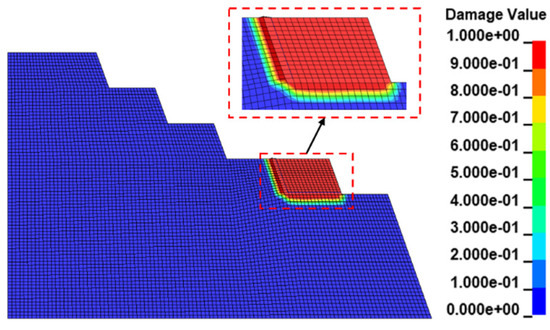
Figure 3.
Cloud image showing the slope damage results.
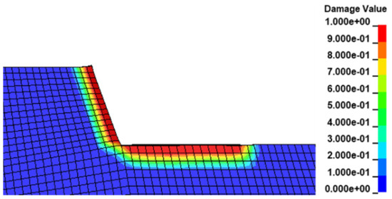
Figure 4.
Bench damage cloud chart results.
Damage to the reserved rock mass was mainly caused by adjacent rock blasting excavation. Eventually the adjacent reserved rock mass bench slope was damaged, caused by a larger damaged area. With increasing distance between the burst center, the degree of damage to the reserved rock mass gradually declined. During explosive detonation, the blast generated by the shock wave blast load instantly reach a peak and the shell hole wall around the rock was instantly crushed, forming a crushing circle. The section near the shell hole wall portion of the rock contained a greater degree of damage, and the damage degree value was close to 1. With an increase in the burst core distance, the shock wave gradually decayed into a stress wave. The stress wave did not directly damage the rock, but it caused new cracks in the rock mass and primary cracks continued to extend and expand with penetration, causing varying degrees of damage to the rock. Therefore, the damage degree values ranged between 0.2 and 0.8. When the stress wave further decayed, and the circumferential tensile stress in the rock was less than the tensile strength of the rock, rock crack development gradually stopped. Therefore, this formed the undamaged rock mass area.
To obtain Ds = 0.592, we substituted GSI = 55 and D = 0 into Equation (9). When the rock GSI had a value other than 100, a disturbance factor of D = 0, and the rock damage degree was not equal to 0, initial damage to the rock mass, caused by fractures in the native rock mass before blasting excavation, was assumed. Similarly, to obtain Ds = 0.91, we substituted GSI = 55 and D = 1 into Equation (9). Thus, when the perturbation factor was 1, the maximum rock damage value was 0.91 and not 1. As shown in Figure 5, the damage degree Ds range (0.592, 0.910) with increasing perturbation factor D exhibited an increasing logarithmic function for the damage degree Ds, and the growth rate slowed.
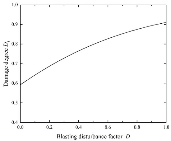
Figure 5.
Curve for damage degree Ds versus the disturbance factor D.
4.2. Determining Rock Mechanical Properties after Blasting Excavation
From the calculated results, we randomly selected 12 sets of data; their damage degrees were 0.616, 0.632, 0.672, 0.699, 0.722, 0.742, 0.782, 0.803, 0.832, 0.867, 0.892, and 0.910. The corresponding disturbance factor D values were obtained by using a calculation program within MATLAB R2020b (Yunnan, China). The D values were input into Equations (2)–(10) to obtain the mechanical properties of the rock mass under different disturbance conditions (i.e., under different damage degrees); the calculated results are shown in Table 5 and Table 6.
Table 5.
Mechanical properties of the undisturbed rock mass.
Table 6.
Mechanical properties of the rock mass after blasting disturbance.
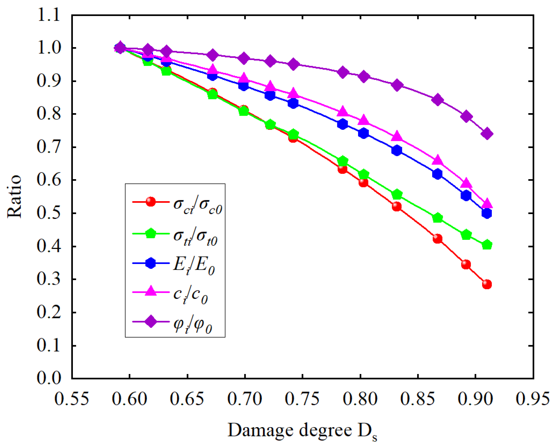
The following rock mass mechanical property ratios , , Ermi/Erm0, crmi/crm0, φrmi/φrm0 were selected to evaluate the attenuation degrees of the mechanical properties for the blasted and undisturbed rock bodies. Smaller ratios indicate greater degrees of property attenuation, as shown in Figure 6.

Figure 6.
Curve diagram showing the rock mechanical parameter changes with damage degree.
The tensile strength of a rock mass declines almost linearly with increasing damage, and the compressive strength, modulus of elasticity, cohesion, and internal friction angle values decreased exponentially with increasing damage. In terms of mechanical property decline, the angle of internal friction decreased slowly with increasing damage, followed by the cohesion and modulus of elasticity. Compressive strength decreased the most rapidly with increasing damage.
4.3. Evolution of Blasting Excavation Slope Damage
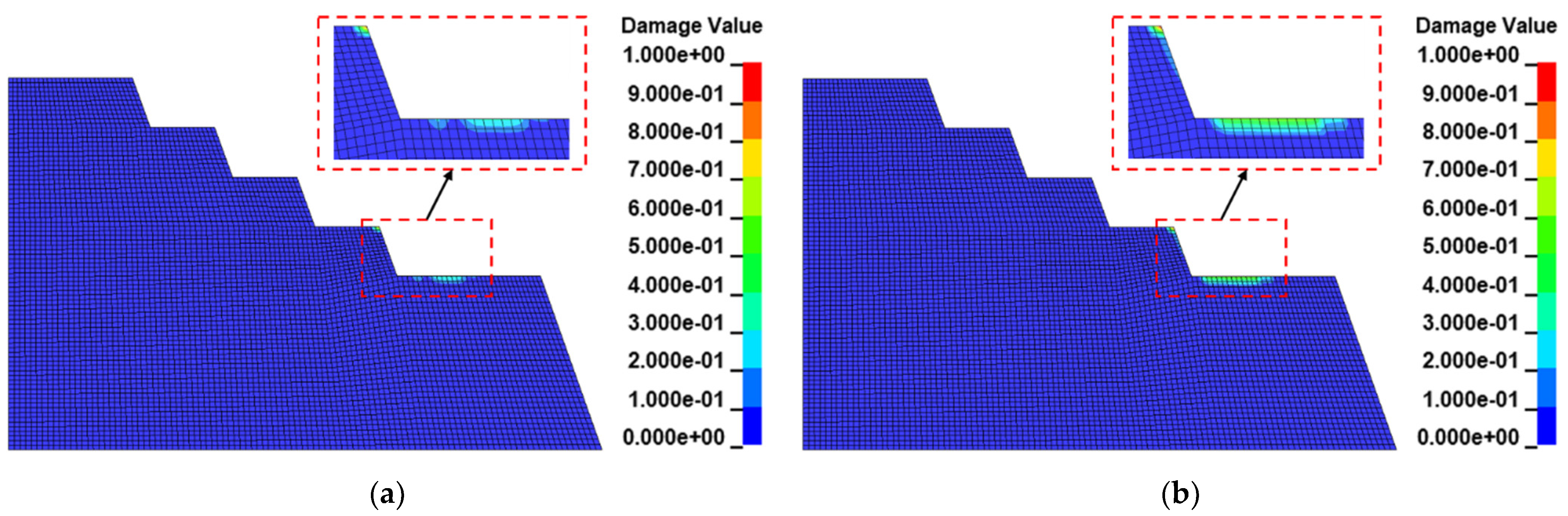
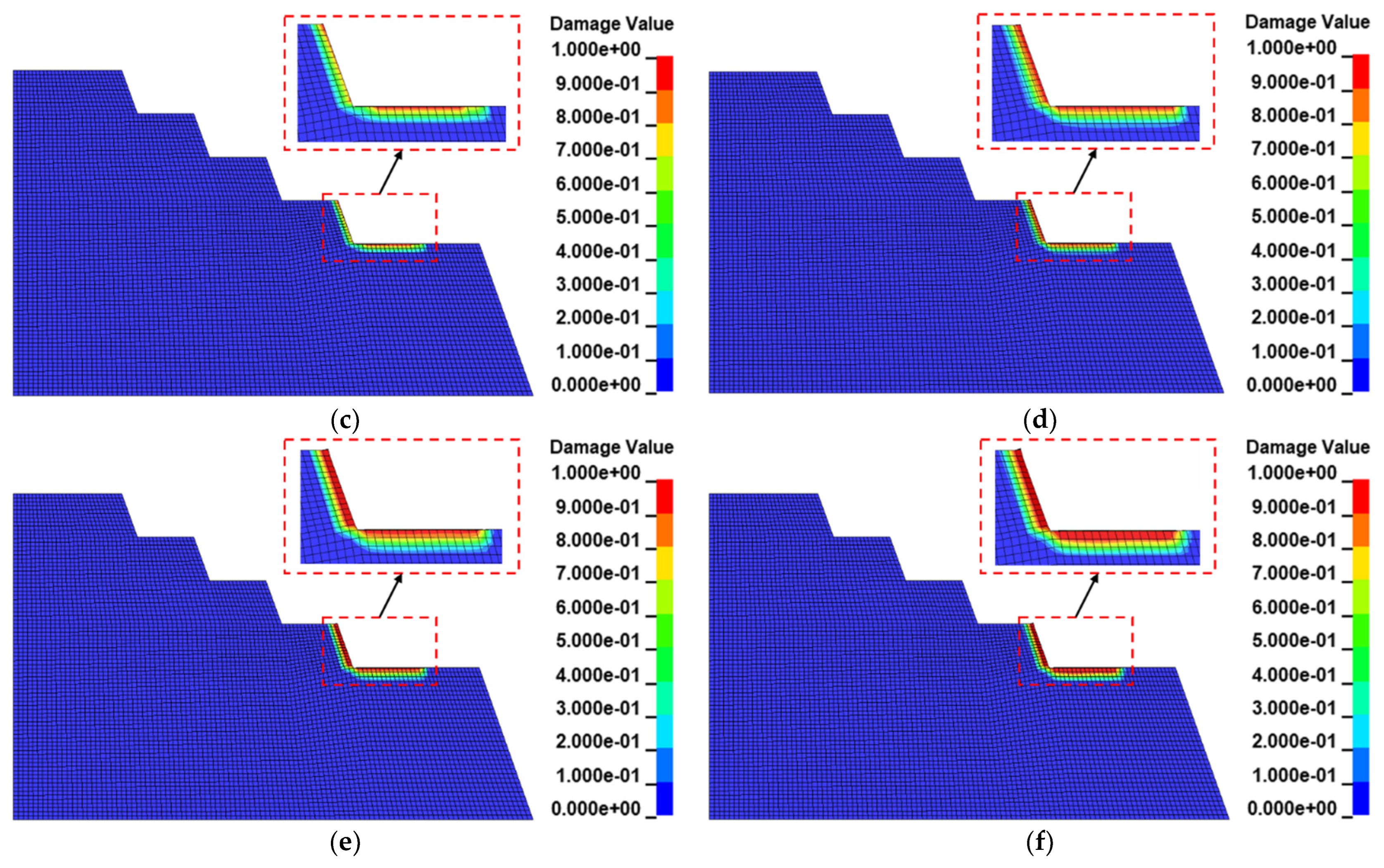
The time course diagram for blasting excavation slope damage is shown in Figure 7. The blasting damage first occurred at the bottom of the reserved rock and the top of the adjacent benches; then, the damage gradually penetrated the bottom. As the blasting process proceeded, a distinct damage zone appeared at the slope bench and gradually extended to the interior of the bench until blasting was complete. Eventually, a damage zone of 1.5 to 2 m in depth formed at the adjacent bench and the bottom portions of the reserved and stripped rocks.
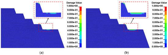
Figure 7.
Damage distribution of the reserved rock mass during blasting excavation: (a) 0.1 ms; (b) 0.2 ms; (c) 0.3 ms; (d) 0.4 ms; (e) 0.5 ms; (f) 0.6 ms.
When the numerical calculation result of the rock damage degree is 0 < Ds < 0.318, the actual damage degree of the rock is 0.592–0.910; when the numerical calculation result is greater than or equal to 0.381, the actual damage degree of the rock is the maximum value of 0.910; that is, the slope has been completely damaged.
4.4. Rock Damage Classification Criteria
Based on Equation (14), the rock level was classified into four classes: extremely stable (I), stable (II), moderately stable (III), and unstable (IV), as shown in Table 7.
Table 7.
Classification of the self-stabilizing capacity of the rock mass.
By combining Equations (11) and (13), we can obtain the basic quality index of the rock mass BQ, according to the correction method for rock mass level slope engineering, following the standard for engineering rock mass classification [24]:
where λ is the correction coefficient of the main structural surface type and extension extensibility for slope engineering, K4 is the correction coefficient for groundwater influence for slope engineering, K5 is the correction coefficient for the main structural surface yield effect for slope engineering, F1 reflects the influence of the relationship between the inclination of the main structural surface and the inclination of the slope, F2 reflects the influence of the main structural surface, F3 reflects the relationship between the request of the slope and the inclination of the main structural surface, and the coefficient F3 reflects the influence of the relationship between the slope request and the inclination of the main surface structure. After statistical analysis, λ was 0.7, K4 was 0.2, F1 was 0.4, F2 was 1.0, and F3 was 0.2. The Ds values selected were 0.592, 0.672, 0.832, and 0.91. The calculated results are shown in Table 8.
Table 8.
Comparison of the self-stabilizing parameters of the rock mass.
Lithology is a function of harder rock as denoted by II-V, which can be used to grade the basic quality of the rock mass, corresponding to I-IV for the self-stabilizing ability grading of the rock mass [24]. Therefore, the damage degree Ds was used as the standard to determine the self-stabilizing grading of the rock mass.
The initial damage degree of the slope was Ds = 0.592, which was medium-stable. However, under blasting action, a damage zone with a depth of ~1.5–2 m formed on the slope surface, and the damage degree of the rock in the damage zone was Ds > 0.6, which corresponded to rock mass grades III and IV.
After blasting excavation, the damage degree Ds > 0.82 corresponded to rock mass grade IV. After the rock mass broke, we observed broken belts, falling blocks, and dumping, which pose significant safety risks to personnel and equipment. When the damage degree Ds was (0.6, 0.82), it corresponded to a rock mass grade of III, where the rock mass was broken, exposing the rock bodies on the slope bench surfaces for that range, with some surfaces occasionally containing falling blocks. Therefore, if necessary, reinforcement measures such as slurry spraying and anchor net hanging should be implemented on these slope surfaces. As the damaged area caused by blasting deepened, the actual width of the slope bench was less than the design width, and over-excavation occurred; therefore, additional actions should be taken such as reducing the size of the hole and changing the loading structure.
5. Conclusions
By introducing a link between the damage degree and the disturbance factor in the Hoek–Brown strength criterion, we quantitatively determined a law for the degree of rock mass damage as a function of disturbance factor changes. We established a numerical model based on data from a phosphate mine slope in Guizhou Province by applying the RHT damage principal model. We then assessed the changes in mechanical properties of the rock under different damage conditions and the following conclusions were drawn.
The tensile strength of the rock mass decreased linearly with increasing damage degree Ds, and the compressive strength, elastic modulus, cohesion, and internal friction angle values of the rock mass decreased non-linearly with increasing damage degree. The internal friction angle exhibited the smallest decline, followed by cohesion and elastic modulus, while compressive strength decreased the most rapidly.
Based on the standard for engineering rock classification and calculations for the damage degree, we established a rock mass self-stabilizing classification standard based on the damage degree Ds. The rock mass self-stability of the mine was classified into four grades: extremely stable (I), stable (II), moderately stable (III), and unstable (IV).
Considering the initial damage to the rock mass, the damage state of the surrounding rock should be considered in the blasting design, and the amount of charge should be appropriately reduced. An appropriate charging structure should also be designed to reduce the damage to the reserved rock mass. Furthermore, after blasting excavation, the slope surface should be properly prepared, and if necessary, the reserved rock mass should be reinforced by slurry spraying or anchor hanging.
In this work, we established a link between damage degree and disturbance factor, and the mechanical properties of the rock mass were derived from the disturbance factor. However, there were limitations in the numerical simulation when we obtained the exact damage depth of the rock mass. Therefore, in future research, more field tests should be conducted and combined with the research results from this study to establish damage degree, damage depth, disturbance factor, and mechanical index values. We also plan to conduct numerous field tests to establish a link between damage degree, damage depth, disturbance factor, and the mechanical index, in order to provide better theoretical support for the estimation of rock mechanics parameters and rock protection in the future.
Author Contributions
Conceptualization, R.Y. and K.L.; methodology, R.Y.; software, R.Y.; validation, Q.Q. and M.L. (Mingliang Li); formal analysis, R.Y.; investigation, R.Y.; resources, M.L. (Meng Li); data curation, R.Y. and M.L. (Mingliang Li); writing—original draft preparation, R.Y.; writing—review and editing, K.L., Q.Q. and M.L. (Mingliang Li); visualization, Q.Q.; supervision, M.L. (Meng Li); project administration, M.L. (Meng Li); funding acquisition, K.L. All authors have read and agreed to the published version of the manuscript.
Funding
This research was funded by the National Natural Science Foundation of China (Grant No. 51934003) and the Program for Innovative Research Team (in Science and Technology) in University of Yunnan Province.
Data Availability Statement
Not applicable.
Acknowledgments
We thank LetPub (www.letpub.com) for linguistic assistance and pre-submission expert review.
Conflicts of Interest
The authors declare no conflict of interest.
References
- Jian, W.; Hong, R.; Fan, X.; Zhou, B. Experimental study of dynamic response of jointed rock slopes under cyclic loads. Chin. J. Rock Mech. Eng. 2016, 35, 2409–2416. [Google Scholar] [CrossRef]
- Li, L.; He, C.; Wang, T.; Zhao, R.; Ju, N. Study on fracture development characteristics and marginal spectral entropy response of soft and hard interbedded slope with steep inclination subjected to strong earthquakes. Rock Soil Mech. 2020, 41, 3456–3464. [Google Scholar] [CrossRef]
- Fei, H.; Yuan, J. Study of slope stability based on blasting cumulative damage. Chin. J. Rock Mech. Eng. 2016, 35, 3868–3877. [Google Scholar] [CrossRef]
- Liu, D. Study on Control Standard about Blasting Vibration Security of High Rock Slop under the Influence of Structure Plane Mechanics Parameters. Master’s Thesis, Changjiang River Scientific Research Institute, Wuhan, China, 2017. [Google Scholar]
- Gong, L.; Wen, P.; Tang, B.; Zhu, Y. Influence of microseismic activity on rock cutting slope. J. Chongqing Jiaotong Univ. 2015, 34, 68–72. [Google Scholar] [CrossRef]
- Zhang, M.; Xu, N.; Chen, W.; Tan, Y.; Dai, F.; Jiang, X.; Li, T. Analysis of microseismic apparent stress characteristics of the left bank slope at Baihetan hydropower station subjected to excavation. Chin. J. Rock Mech. Eng. 2018, 37, 4133–4141. [Google Scholar] [CrossRef]
- Yan, P.; Zhang, C.; Gao, Q.; Lu, W.; Chen, M.; Zhou, C. Acoustic wave test on mechanical properties variation of rocks under different damage degrees. Rock Soil Mech. 2015, 36, 3425–3432. [Google Scholar] [CrossRef]
- Wu, Y. Blasting Damage Study of Surrounding Rock in Badaling Tunnel. Ph.D. Thesis, China University of Mining and Technology, Beijing, China, 2019. [Google Scholar]
- Song, G.; Shi, X.; Chen, S. New method for determining blasting vibration damage criterion on open-pit slope and its application. J. Cent. South Univ. Technol. 2000, 31, 481–484. [Google Scholar] [CrossRef]
- Chu, H.; Ye, H.; Yang, X.; Liang, W.; Yu, Y. Experiments on propagation of blasting vibration based on damage accumulation. J. Vib. Shock 2016, 35, 173–177. [Google Scholar] [CrossRef]
- Zhang, B.; Liu, W.; Deng, J.; Liu, J. Damage mechanism and stress wave spectral characteristics of rock under tension. Chin. J. Geotech. Eng. 2016, 38, 336–341. [Google Scholar] [CrossRef]
- Sun, Z.; Yu, Q.; Yang, J. Numerical simulation of bench blasting vibration based on continuum damage constitutive model. Acta Armamentarii 2016, 37, 232–235. [Google Scholar]
- Zhang, Q.; Cheng, G.; Lu, X.; Xu, Z.; Dong, H. Multivariate nonlinear model of blasting vibration velocity attenuation considering rock mass damage. J. Saf. Sci. Technol. 2018, 14, 95–101. [Google Scholar] [CrossRef]
- Liu, X.; Deng, Z.; Liu, Y.; Liu, S.; Lu, Y. Study of cumulative damage and failure mode of horizontal layered rock slope subjected to seismic loads. Rock Soil Mech. 2019, 40, 2507–2516. [Google Scholar] [CrossRef]
- Hoek, E.; Carranza-Torres, C.; Corkum, B. Hoek-Brown failure criterion—2002 edition. In Proceedings of the 5th North American Rock Mechanics Symposium and 17th Tunnelling Association of Canada Conference (NARMS-TAC’02), Toronto, ON, Canada, 7–10 July 2002; pp. 267–273. [Google Scholar]
- Yan, C.; Li, G.; Chen, D.; Liu, Z.; Liu, J. Amended expressions of Hoek-Brown criterion based on blasting cumulative damage effects of rock mass. Rock Soil Mech. 2011, 32, 2951–2956. [Google Scholar] [CrossRef]
- Shi, J.; Miao, X.; Chen, H.; Huang, Z.; Zhang, X. Parameters correction of Hoek-Brown rock strength criterion based on fuzzy prediction. Eng. Blasting 2021, 27, 19–28. [Google Scholar] [CrossRef]
- Xia, K.; Chen, C.; Liu, X.; Zheng, Y.; Zhou, Y. Estimation of rock mass mechanical parameters based on ultrasonic velocity of rock mass and Hoek-Brown criterion and its application to engineering. Chin. J. Rock Mech. Eng. 2013, 32, 1458–1466. [Google Scholar] [CrossRef]
- Li, S.; Xue, Y. Modification of Hoek-Brown criterion and its application. Chin. J. Rock Mech. Eng. 2016, 35, 2732–2738. [Google Scholar]
- Haghnejad, A.; Ahangari, K.; Moarefvand, P.; Goshtasbi, K. Numerical investigation of the impact of rock mass properties on propagation of ground vibration. Nat. Hazards 2019, 96, 587–606. [Google Scholar] [CrossRef]
- Yang, Z.; Lu, W.; Gao, Q.; Yan, P.; Chen, M.; Hu, H. Back analysis and calculation of dynamic mechanical parameters of rock mass with measured blasting vibration signals. Math. Probl. Eng. 2018, 2018, 7297945. [Google Scholar] [CrossRef] [Green Version]
- Yang, J.; Dai, J.; Yao, C.; Jiang, S.; Jiang, Q. Weakening laws of rock mass properties in blasting excavation damage zone of high rock slopes. Chin. J. Geotech. Eng. 2020, 42, 968–975. [Google Scholar] [CrossRef]
- Hoek, E.; Brown, E.T. The Hoek–Brown failure criterion and GSI—2018 edition. J. Rock Mech. Geotech. Eng. 2019, 11, 445–463. [Google Scholar] [CrossRef]
- GB/T 50218-2014; Standard for Engineering Classification of Rock Mass. China Planning Press: Beijing, China, 2015.
- Ishihara, K.; Tatsuoka, F.; Yasuda, S. Undrained deformation and liquefaction of sand under cyclic stresses. Soil Found. 1975, 15, 29–44. [Google Scholar] [CrossRef] [Green Version]
- Riedel, W.; Thoma, K.; Hiermaier, S.; Schmolinske, E. Penetration of reinforced concrete by BETA-B-500: Numerical analysis using a new macroscopic concrete model for hydrocodes. In Proceedings of the 9th International Symposium on the Interaction of the Effects of Munitions with Structures (ISIEMS’99), Berlin, Germany, 3–7 May 1999; pp. 315–322. [Google Scholar]


Publisher’s Note: MDPI stays neutral with regard to jurisdictional claims in published maps and institutional affiliations. |
© 2022 by the authors. Licensee MDPI, Basel, Switzerland. This article is an open access article distributed under the terms and conditions of the Creative Commons Attribution (CC BY) license (https://creativecommons.org/licenses/by/4.0/).