Article

Numerical Study of Heat Transfer in a Gun Barrel Made of Selected Steels

Faculty of Mechatronics, Armament and Aerospace, Military University of Technology, ul. gen. S. Kaliskiego 2, 00-908 Warsaw, Poland
*
Author to whom correspondence should be addressed.
Energies 2022, 15(5), 1868; https://doi.org/10.3390/en15051868
Submission received: 13 January 2022 / Revised: 23 February 2022 / Accepted: 25 February 2022 / Published: 3 March 2022

Abstract

:
The results of numerical simulations of transient heat transfer in the barrel wall of a 35 mm caliber cannon for a single shot and the sequences of seven shots and sixty shots for chosen barrel steels are presented. It was assumed that the cannon barrel was made of one of the three types of steel: 38HMJ (1.8509), 30HN2MFA and DUPLEX (1.4462). To model the thermal phenomena in the barrel, the barrel wall material was assumed to be homogeneous and the inner surface of the barrel had no protective chromium or nitride layer. The calculations were made for temperature-dependent thermophysical parameters, i.e., thermal conductivity, specific heat and thermal expansion (in the range from RT up to 1000 °C) of the selected barrel steels. A barrel with a total length of 3150 mm was divided into 6 zones (i = 1, …, 6) and in each of them, the heat flux density was calculated as a function of time q ˙ i ( t ) on the inner surface of the barrel. Using lumped parameter methods, an internal ballistic code was developed to compute in each zone the heat transfer coefficient as a function of time hi(t) and bore gas temperature as a function of time Tg(t) to the cannon barrel for given ammunition parameters. A calculation time equaling 100 ms per single shot was assumed. The results of the calculations were obtained using FEM implemented in COMSOL Multiphysics ver. 5.6 software.

1. Introduction

It is well known that modern anti-aircraft artillery systems consist of a number of guns, some of which fire at the designated target, while the remaining guns follow the target without firing a shot. This is due to the timing of the single cannon being fired, which is chosen because the high temperatures in the barrel prevent the gun from being fired. In the case of overheating the barrel of one of the guns, it loses its ability to fire. Shooting is then taken over by the other guns that track the target on standby mode. It is also possible to fire all battery guns at once. Low barrel life is a bottleneck that limits the improvement of the weapon’s performance for a long time. Many years of research have shown that the erosion of the internal bore is a direct cause that affects the service life of the barrel. The erosion of the inner surface of the barrel is caused by the action of heat, chemistry and mechanics, with heat playing a leading role [1,2,3,4,5,6,7,8]. Although the mechanism of gun barrel wear is not fully understood, it is known that wear is very closely related to the maximum temperature of the bore surface [9]. Usually, when designing the firing cycle, it is essential to maintain the temperature below 800 °C, established by the manufacturer as a maximum temperature when testing the gun barrel’s life [9,10]. The maximum temperature limit of the barrel bore in operation is dictated by the thermophysical properties of the steel grade of the barrel. In the steel grades under consideration in our paper, a temperature above 800 °C causes allotropic changes connected with the reconstruction of the crystal lattice of the alloy [11,12]. The kinetics of change is well described by the dilatometric curve characteristics for the individual steel grades [11,12,13]. The effect of temperature on the barrel bore alters the volume of the surface layer, giving rise to a typical mesh of cracks. This affects the flaking off of the protective coating on the inner surface of the barrel. In older technological processes, the protective coating consists of electroplated chromium. Currently, this process is being replaced by nitriding. In any case, the protective coating is corroded by the structural transformations in the steel layer, which are directly related to the phase transition between ferrite and austenite [3,12,14]. At present, research is being conducted on the implementation of new steel grades with a higher allotropic transition temperature into the production of gun barrels [12]. It is about shifting the ferrite–austenite phase transition towards a higher temperature or using steels in which this transition does not take place [11]. When calculating the heat transfer in the barrel, constant values of thermal conductivity, specific heat and the density of the barrel material are often taken [9,14,15]. Many publications believe that the thermal properties of the gun barrel material are temperature dependent [16,17,18,19,20]. As a rule, the temperature dependence of the barrel material density is neglected due to small changes [16]. It is very important to correctly introduce the thermophysical properties of new steel grades as input data for the heat transfer calculations in the barrel. We consider a phase change only in relation to the thermal conductivity. However, in the literature, one can find papers in which the thermal effect of the phase transformation has been included twice, i.e., in thermal conductivity and specific heat, which seems to be an erroneous [16]. Thermal diffusivity a, thermal conductivity k, specific heat cp and density ρ are related to the expression a = k/(ρ·cp). Each of these thermophysical parameters can be determined on separate measuring stations or, for example, the thermal conductivity can be calculated from the expression k = a·ρ·cp. The phase transformation is visible in each thermophysical parameter. Thus, when calculating the thermal conductivity k in the phase transition region from formula k = a·ρ·cp, this effect will be taken into account both in thermal diffusivity and in specific heat. This means that the phase change effect and the associated enthalpy will be accounted for twice. As a rule, we consider the phase transition effect in thermal conductivity characteristic [21]. During the continuous firing of artillery, the inner wall of the barrel will experience a continuous rise of temperature. On each curve of the barrel temperature increase during the shot we can distinguish the so-called highest peak temperature and lowest temperature of the peak base, which is in fact the inner wall temperature of the barrel. In order to reach the temperature of 800 °C of the inner barrel surface, it is often necessary to carry out numerical simulations of the heat transfer in the barrel after firing several dozen shots [14,18,19].
Over the years, numerous research groups have carried out a series of tests to determine the temperature field of the gun barrel. These calculations are becoming more and more accurate and verifiable in experimental research [1,15,22,23]. However, it is often important to simulate heat transfer throughout the barrel, not just a fragment of it. In order to avoid very time-consuming calculations, the barrel can be divided into sectors. In this paper an initial boundary value problem (IBVP) of heat transfer in the barrel wall of a 35 mm caliber cannon was solved for the single shot and the sequence of seven shots for chosen barrel steels. For calculation purposes, the barrel with a total length of 3150 mm has been divided into six zones S1 to S6—Figure 1. The heat transfer coefficient was calculated as a function of the time hi(t) in the six cross-sections P1 to P6 on the inner surface of the barrel: P1: z = 216 mm, P2: z = 385 mm, P3: z = 535 mm, P4: z = 880 mm, P5: z = 2081 mm, P6: z=2980 mm and the gas temperature as a function of time Tg(t). The functions hi(t) in cross-sections P1 to P6 are valid in the zones S1 to S6. Additionally, the S0 zone of the cannon breech was distinguished in the range from 0 to 216 mm, for which—at the present stage of the research—the same function hi(t) was assigned as for the S1 zone. The calculations were carried out considering the temperature-dependent thermophysical parameters in the model, i.e., thermal conductivity, specific heat and thermal expansion (in the range from RT to 1000 °C). In 2020, the authors of this study tested the thermophysical properties of selected barrel steels, i.e., 38HMJ (1.8509), 30HN2MFA and DUPLEX (1.4462) (in the range from RT to 1000 °C) [12]. In this study, particular attention was paid to the correct introduction of thermophysical parameters depending on the temperature in the numerical heat transfer tests in the barrel wall of a 35 mm caliber cannon for a single shot and the sequence of shots for the chosen barrel steels. The idea is not to erroneously consider the phase transition effects on the selected metals twice, such as in thermal conductivity and specific heat.

1.1. Determination of the Heat Transfer Coefficient and Gas Temperature

The heat transfer coefficient can be calculated from a convective heat transfer correlation for a fully developed turbulent pipe flow, which expresses the Nusselt number Nu as a function of the Reynolds Re and Prandtl Pr numbers [25]:
N u D = 0.023   R e D 0.8 P r 0.4
For fluid flow in a pipe of circular cross section of diameter D, if the gas has a velocity w, density ρ, dynamic viscosity µ and thermal conductivity kp, the definitions of the Nusselt and Reynolds numbers are, respectively:
N u D = h D k p R e D = ρ w D µ
By substituting Equation (2) into Equation (1), one can express h in the form:
h = 0.023 D 0.2 · k p μ 0.8 P r 0.4 ( ρ w ) 0.8
The approximate value of the Prandtl number can be calculated using the simplified Eucken formula [23,25]:
P r = 4 γ 9 γ 5
where γ is adiabatic index of the gunpowder gases. For γ   = 1.20, we have P r 0.4 0.93 .
Considering the weak temperature dependence of the k p μ 0.8 285 relation (for the average temperature of the gunpowder gases equal to 1000 °C), we have [25,26]:
h = 6.1 D 0.2 ( ρ w ) 0.8 .
Since the density ρ and velocity w of the gunpowder gases are functions of time, we have different values of the time-dependent heat transfer coefficient h in the cross-section P1 to P6 of the 35 mm cannon barrel. In the adopted model of heat transfer in the gun barrel, we assume that the calculations ρ and w in the cross-section P1 to P6 are also valid in zones S1 to S6, respectively.
Density ρ, velocity w and bore gas temperature as a function of time T g ( t ) can be determined by solving the interior ballistic model, which is a model with lumped parameters [27,28,29]. The calculations took into account the phenomena occurring in the barrel until the projectile exits the barrel and the after muzzle period. The condition for completing the calculation is that the propellant pressure in the barrel drops to 0.18 MPa [30].
When the projectile is in the barrel, the model contains:
Energy conservation equation (the first law of thermodynamics):
d U = d Q d W
Here, differential of internal energy d U taking into account mass fraction of burning propellant ‘zp’ with respect to its initial mass m p has the form:
d U = d ( c v m p z p T ) = c v m p ( T d z p + z p d T )
Amount of heat d Q release during burning of propellant of isochoric flame temperature T 1 and specific heat at constant volume c v equals:
d Q = c v T 1 m p d z p
Amount of sum of works of propellant gases d W taking into account coefficient of secondary works φ is given by:
d W = d ( φ m v 2 2 ) = φ m v d v
Substituting Equations (7)–(9) into Equation (6) and replacing c v by c v = R γ 1 after some algebraic manipulations, we obtain:
d ( R T ) d t = ( f R T ) m p d z p d t ( γ 1 ) φ m v d v d t m p z p
where f = R T 1 , γ = c p / c v .
Equation of state of propellant gases [27,28,29]:
p ( V 0 + s l m p ρ p ( 1 z p ) η m p z p ) = m p z p R T
Equation of mass fraction burning rate of the propellant (gas inflow) [27,28,29]:
d z p d t = S 1 Λ 1 1 + 4 λ 1 κ 1 z p r 1 p
Equation of the projectile motion:
φ m d v d t = p s
where φ = K + 1 3 m p m .
Definition of the projectile velocity:
d l d t = v
Propellant gas density:
ρ = m p z p V 0 + s l m p ρ p ( 1 z p ) η m p z p
Assuming a linear distribution of the velocity of the propellant gases in the barrel, we calculate the velocity w of gases in the considered cross-section i = 1, …, 6, (i–a cross-section number from P1 to P6) of the barrel according to:
w = l i l 0 + l v
where: l i —distance from the bottom of the chamber to the cross-section i of the barrel; l 0 —length of the canon chamber, l —projectile travel inside the barrel.
In the period after the projectile muzzle, the model includes:
Energy conservation equation, taking into account the outflow of gases to the environment (through the muzzle of the barrel):
d U = d Q d H
Considering that:
d U = d [ c v m p ( z p ζ ) T ] = m p R γ 1 [ T ( d z p d ζ ) + ( z p ζ ) d T ]
d Q = c v T 1 m p d z p = 1 γ 1 f m p d z p
d H = c p m p T d ζ = γ γ 1 m p R T d ζ ,
Equation (17) takes the form:
d ( R T ) d t = ( f R T ) d z p d t ( γ 1 ) R T d ζ d t z p ζ
Equation of state of propellant gases [27,28,29]:
p ( V 0 + s l m m p ρ p ( 1 z p ) η m p ( z p ζ ) ) = m p ( z p ζ ) R T
Propellant gas density:
ρ = m p ( z p ζ ) V 0 + s l m m p ρ p ( 1 z p ) η m p ( z p ζ )
Rate of mass fraction of propellant gases flowing out of from the barrel (gas outflow):
d ζ d t = s p m p R T γ ( 2 γ + 1 ) γ + 1 γ 1
Assuming that the propellant gases flowing out of the barrel reach critical parameters, their velocity in the considered cross-section i of the barrel will be calculated according to:
w = l i l 0 + l m w c r
where w c r = γ R T c r = 2 γ γ + 1 R T ; w c r , T c r —critical velocity and critical temperature of propellant gases at the muzzle.
The initial conditions for calculations are the following:
t = 0 ,   R T = R T 1 = f ,   z p = 0.001 ,   l = 0 ,   v = 0 ,   ζ = 0 .
It should be added that the variables zp(t), l(t), v(t), T(t), ζ ( t ) , w(t), ρ(t) and p(t) are functions of time. The input data for the interior ballistic calculations are shown in Table 1.
The calculation results of the heat transfer coefficient as a function of time h i ( t ) in the six cross-sections P1 to P6 and the gas temperature as a function of time T g ( t ) for the 35 mm anti-aircraft cannon barrel are shown in Figure 2, and so the values of h i ( t ) in the section P1 are valid in the zone S0 and S1, P2 in the zone S2, P3 in the zone S3, etc. In this paper, zone S1 includes the zone S0 of the cannon breech. Detailed and precise calculations of heat transfer in the S0 zone are not the subject of the study.
For t = 4.54 ms, we observe rapid drops of the heat transfer coefficient as a function of time h i ( t ) in each of the six cross-sections P1 to P6. This is the moment when the bullet leaves the barrel. The highest value is achieved by the heat transfer coefficient in the fourth zone. It has a slightly lower value in zone three.

1.2. Thermophysical Properties of Selected Barrel Steels

The thermophysical properties, i.e., thermal conductivity, specific heat and density as a function of temperature in the RT range up to 1000 °C, were adopted as a contribution to the initial boundary value problem of heat transfer in the barrel wall of a 35 mm caliber cannon, as shown in Figure 3, Figure 4 and Figure 5 and in Table 2, Table 3 and Table 4.
For the selected steels, the experimental data on thermal conductivity was introduced in the form of Table 2. Data between measurement points were approximated in COMSOL software using cubic splines.
The experimental specific heat data are presented in Table 3 and illustrated in Figure 4. Data between points were approximated in COMSOL using cubic splines.
The experimental density data are presented in Table 4 and illustrated in Figure 3. Data between points were approximated in COMSOL using cubic splines.
Our tests described in [12] showed that for the 38HMJ steel at about and 30HN2MFA at about 740 °C there was a ferrite–austenite phase transition, which was responsible for the material shrinkage. In numerical simulations of heat transfer in the cannon barrels, the energy related to the phase transition was included only in the material density and thermal conductivity, while in the specific heat this energy was ignored. Phase transition energy should not be taken into account multiple times, e.g., both in thermal conductivity and specific heat [12].

2. Initial Boundary Value Problem

The results of the transient heat transfer numerical simulations in the wall of a 35 mm cannon barrel for a single shot and for a sequence of shots has been presented in this paper. The initial temperature of the cannon was assumed as T 0 = 20   ° C . The heat transfer on the barrel’s outer surface was modeled as a boundary condition of the 3rd kind in a form q . = h out · ( T ( t , r z , z ) T 0 ) . An equivalent heat transfer coefficient value of h o u t = 9.2   W / ( m 2 · K ) was assumed to be the same on the entire outer surface of the barrel. The governing equation for nonlinear and axially symmetrical 2D IBVP is as follows:
ρ s ( T ) c s ( T ) T t = 1 r r ( k s ( T ) r T r ) + z ( k s ( T ) T z )
with
r i n < r < r o u t , 0 < z < l m ,   t   >   0 ,
where T is the temperature of the gun barrel, t is the time, r is the distance between node and the barrel axis line, ρ is the density of barrel material, and c is the specific heat of barrel material, with the initial condition:
T ( 0 , r , z ) = T 0   with   r i n < r < r o u t   0 < z < l m   and   t = 0
and the boundary conditions:
q ˙ i ( t , r = r i n ,   z ) = h i ( t ) · ( T ( t , r i n , z ) T g ( t , r i n , z ) ) ,   i = 1 ,     , 6 ,
(i–a zone number from S1 to S6)
q ˙ = h o u t · ( T ( t , r o u t , z ) T 0 ) ,  
where T g is the gas temperature calculated by solving the internal ballistic model, r i n = 35 2 mm, r o u t dependent on the variable zFigure 1.
The same IBVP was solved for the series of shots (27) to (30). The initial condition for the next shot was taken from the previous solution, i.e., T ( t j , r , z ) = T ( 0 , r , z ) , with j standing for the number of shot. The boundary conditions remained unchanged during calculations. The calculations were made using FEM implemented in the COMSOL Multiphysics program. The number of mesh elements, including quad elements, is 26,200. Minimum element quality equals 0.8563. Duration of a single shot was 100 ms. A sequence of shots was adopted for the simulation of burst firing. The calculations were made on 6 sections of the barrel S1 to S6 (z in the middle of each zone). The numerical experiment was carried out on the DELL PRECISION TOWER 5610 workstation equipped with an Intel (R) Xeon (R) CPU ES-1620 v3 @ 3.50GHZ with 16 GB RAM under Windows 10 Operating System. The total computation time of the sixty shots was approximately 6 h. Mesh compaction near the inner surface was performed with a geometric sequence with length element ratio equaling 0.81 and the mesh between the zones compacted five times—Figure 6.

2.1. Temperature Distibution in the Cannon Barrel for a Single Shot

For each of the selected steels, the temperature distributions T i ( t , r i n , z ) of the barrel’s inner surface at the 6 zones S1 to S6 (z in the middle of each zone) for the single shot are shown separately in Figure 7. In each zone, the heat transfer coefficient as a function of time h i ( t ) is different—Figure 2. The dashed line on each Figure shows the time the bullet left the barrel (t = 4.54 ms).
The highest temperature, i.e., the so-called highest peak temperature occurs for DUPLEX steel. The 38HMJ and 30HN2 MFA steels behaved similarly, i.e., the temperature distribution T i ( t , r i n , z ) of the inner surface of the barrel in the six zones S1 to S6 (z in the middle of each zone) were practically the same for one shot. For each selected steel, zone S3 had the highest temperature (Figure 8). The disturbance of the temperature distribution T i ( t , r i n , z ) of the inner surface barrel in zone S5 was caused by a rapid decrease in the heat transfer coefficient h i ( t ) at the moment the bullet left the barrel—Figure 1. In zone S6, this effect did not occur because the bullet travelled there too briefly.

2.2. Temperature Distibution in the Cannon Barrel for a Series of Seven Shots

In all the presented calculations, we assume the time-dependent heat flux density on the inner surface of the barrel changes for the first and subsequent shots. This is because the temperature of the inner surface of the barrel changes. For the selected steels, the temperature distribution T i ( t , r i n , z ) of the barrel’s inner surface at the six sections S1 to S6 (z in the middle of each zone) for the series of seven shots is shown in Figure 9.
The lowest temperature, i.e., the lowest peak temperature, for 38HMJ and 30HN2MFA steel was the same for each shot in a series of seven shots. However, in the case of DUPLEX steel, this temperature was higher for each shot in a series of seven shots compared to the 38HMJ and 30HN2MFA steel.

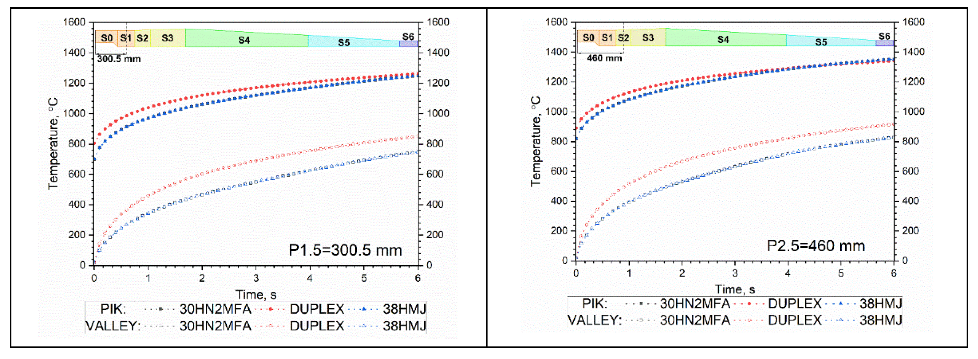
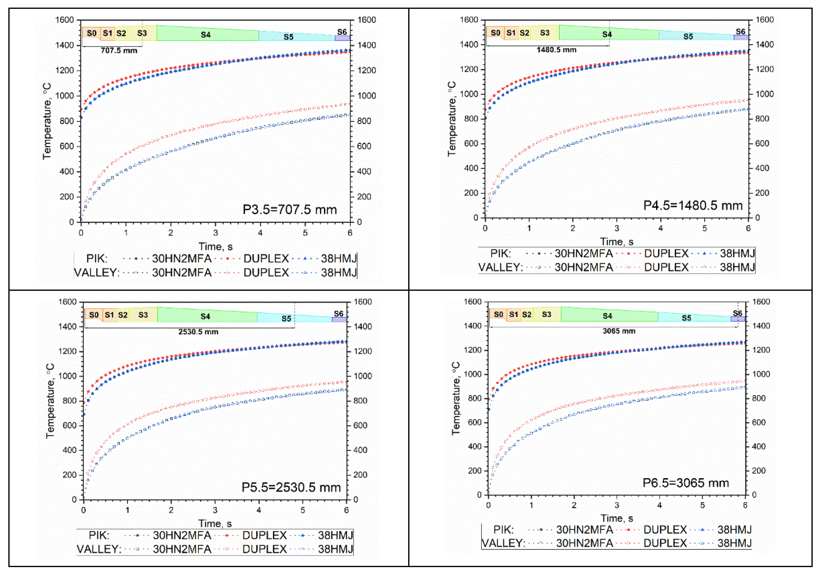
2.3. Temperature Distibution along the Barrel Thickness for a Series of Seven Shots

For the selected steels, temperature distributions T i ( t , r , z ) along the barrel thickness for a sequence of seven shots in zone S6 (z in the middle of the sixth zone) and for the for the first, fourth and seventh shots in zone S6 are shown in Figure 10. In addition, the temperature distributions T i ( t , r , z ) along the barrel thickness for the selected steels for the first, fourth and seventh shots separately are illustrated in Figure 11.
Figure 11 shows the temperature distributions T i ( t , r , z ) along the barrel thickness for a sequence of seven shots in zone S6 (z in the middle of the sixth zone) for all three selected steels: for shot 1—in the upper figure, for shot 4—in the middle figure, for shot 7—in the bottom drawing.

2.4. Temperature Distibution in the Cannon Barrel for a Series of Sixty Shots

Thermophysical properties, i.e., thermal conductivity, specific heat and density as a function of temperature in the range of 1000 °C to 1300 °C, were obtained by the linear extrapolation of experimental data of the selected steels in the RT range up to 1000 °C. For the selected steels, temperature distributions T i ( t , r , z ) of the barrels inner surface and along the barrel thickness for a sequence of sixty shots in each zone S1 to S6 (z in the middle of each zone) are shown in Figure 12 for 30HN2MFA steel and Figure 13 for DUPLEX steel. The results for the 38HMJ steel are very similar to the results for the 30HN2MFA steel, therefore they are not shown in a separate drawing.
Figure 14 shows the envelopes of the so-called highest peak temperatures and lowest peak base temperatures for 60 shots for all selected steels. For 38HMJ and 30HN2MFA steels, the lines match blue.

3. Discussion

The results of numerical tests of the heat transfer in the barrel of the 35 mm anti-aircraft gun made of three selected steel grades showed a similar nature of heat transfer in the 38HMJ and 30HN2MFA steels, but a different one in the Duplex steel. The heat transfer model is relatively simple and the obtained values of temperature fields on the inner surface of the barrel were not overestimated, as they were in the paper [24]. The division of the cannon into six zones S1 to S6 was agreed with the Polish weapons manufacturer. As numerical tests of heat transfer in the barrel are very time-consuming, such a division method reduces the calculation time to several hours for one steel.
In the case of a single shot—the temperature on the inner surface of the barrel:
In DUPLEX steel, the maximum temperature of the inner surface of the barrel, i.e., so-called highest peak temperature was about 87 °C higher than for the other two steels, and it dropped less than the other two. It results from a lower value of thermal diffusivity coefficient as a function of the Duplex steel temperature in relation to the other two. In each of the three selected steels, the maximum temperature of the inner surface of the barrel occurred in the third zone, S3. In the second, S2, and fourth, S4, zones, the temperatures were not much lower. In addition, the maximum temperatures on the inner surface of the barrel in the first four zones, S1 to S4, occurred before the exit of the bullet from the barrel, while the maximum temperatures in the fifth zone, S5, and the sixth zone, S6, occurred after the bullet exited the barrel.
In the case of the sequence of seven shots—temperature on the inner surface of the barrel:
In DUPLEX steel in the S3 zone, the highest temperature and the lowest temperature of the inner surface, i.e., the so-called highest peak temperature and lowest temperature of the peak base after the seven shots reached the values of 1088 °C and 462 °C, respectively—Figure 9. The difference between the highest and lowest inner surface temperature was maximum and equal to 626 °C in the S3 zone and minimum and equal to 468 °C in the S6 zone—Figure 9. In the 38HMJ and 30HN2MFA steels in the S3 zone, the lowest and the highest temperature of the inner surface after seven shots reached the values of 345 °C and 1039 °C for 30HN2MFA steel, and 355 °C and 991 °C for 38HMJ steel, respectively. The difference between the highest and lowest inner surface temperature for these steels was maximum and equal to 694 °C for 30HN2MFA steel and 636 °C for 38HMJ steel in the S3 zone and the minimum and equal to 552 °C for 30HN2MFA steel and 507 °C for 38HMJ steel in the S6 zone. For each of the selected steels, the lowest temperature reached its maximum in the S6 zone, and the increase in the lower internal surface temperature, i.e., in the lowest temperature of the peak base became an almost linear function of the number of shots.
In the case of the sequence of seven shots—the calculation of heat transfer along the barrel thickness:
On each curve of increasing temperature of the inner surface of the barrel during the shot, we could distinguish the so-called highest peak temperature and the lowest base temperature, which was in fact the temperature of the inner wall of the barrel. This temperature was practically identical to the temperature of the barrel wall at a depth of 0.5 mm below its inner surface—Figure 10. Therefore, it can be assumed that the temperature of the inner surface of the barrel during a series of shots is equal to the barrel temperature at a depth of 0.5 mm below its surface. Temperature distributions T i ( t , r , z ) along the barrel thickness for selected steels for the first, fourth and seventh shots are shown in Figure 11. At a depth of 0.5 mm, the greatest temperature difference occurred between 30HN2MFA, 38HMJ steels and DUPLEX steel. The difference increased with subsequent shots and after the seventh shot in the zone S6 it was about 86 °C—Figure 11 (lower drawing).
In the case of the sequence of sixty shots—the temperature along the barrel thickness:
After sixty shots, the highest internal surface temperature of the barrel occurred in the S3 zone and for all three steel grades, i.e., 30HN2MFA, 38 HMJ and DUPLEX steel, it was similar and amounted to approx. 1363 °C for 30HN2MFA and 38 HMJ steels, and 1348 °C for DUPLEX steel—Figure 12, Figure 13 and Figure 14.
The lowest temperature of the internal surface in DUPLEX steel occurred in zones S1 and S2, i.e., around 849 °C in zone S1 and 916 °C in zone S2. For the remaining steels, the lowest temperature also occurred in zones S1 and S2, i.e., about 748 °C for 30HN2MFA and 38 HMJ steels in zone S1 and 827 °C for 30HN2MFA and 38 HMJ steels in zone S2. This is due to the fact that DUPLEX steel heats up to a higher temperature and cools down slowly as it has a lower thermal diffusivity coefficient than 30HN2MFA and 38HMJ steels. As it cools more slowly, the highest internal surface temperature after sixty shots is also lower than it would have been if this shielding effect, which is associated with an increase in inner wall temperature after each shot, was not observed in the heat flux density calculation. It should also be remembered that for 38HMJ and 30HN2MFA steels there is a shrinkage of the material and a phase change at a temperature of about 800 °C. The internal surface temperature of about 800 °C was achieved in 30HN2MFA and 38HMJ steels after about thirty shots in zone S5 (after 3.0 s) and S6 (after 2.9 s) and after about sixty shots in zone S1 (after 5.9 s)—Figure 12. It also means that the inner surface of the barrel in zones S5 and S6 will wear out the fastest. Due to the integral heat propagation effect in the steel, no changes were observed in the highest or lowest temperature of the inner surface of the barrel in the case of 30HN2MFA or 38HMJ steels specifically related to this shrinkage effect. After sixty shots, the maximum temperature of 30HN2MFA and 38HMJ steels and Duplex steel in the S2 to S4 zones was practically the same and was about 1363 °C for 30HN2MFA and 38 HMJ steels and 1348 °C for DUPLEX steel, while the lowest temperature in the 30HN2MFA and 38HMJ steels in the S5 and S6 zones was about 892°, and in DUPLEX steel it was about 955 °C in zone S5 and 944 °C in zone S6. After sixty shots, the outer surface of the barrel in zone S6 heated up to a temperature of about 226 °C for 30HN2MFA steel and 230 °C for 38 HMJ steel, and to 103 °C for DUPLEX steel–Figure 12 and Figure 13. For selected steels, the envelopes of the highest and the lowest temperatures are shown in Figure 14. There were only differences between DUPLEX steel and the other steels, i.e., 30HN2MFA and 38HMJ.

4. Conclusions

The calculations of the heat transfer in the barrel of the 35 mm anti-aircraft gun were made for the temperature-dependent thermophysical parameters, i.e., thermal conductivity, specific heat and thermal expansion (in the RT range up to 1000 °C) of the selected barrel steels. The paper indicates that the energy of the phase transformation should not be taken into account multiple times, e.g., both in terms of thermal conductivity and specific heat.
The results of the numerical simulation of the heat transfer in the barrel of the 35 mm anti-aircraft cannon are summarized as follows:
(1) After the first shot, the maximum temperature on the inner surface of the barrel, the so-called highest temperature is the highest in DUPLEX steel—Figure 7. The temperature difference in relation to the other two steels is about 87 °C in zone S3 and decreases with successive shots, and after about 4 s and about 40 shots it is similar to the temperature of DUPLEX steel (in zone S3)—Figure 14. After sixty shots, the highest temperature of the 30HN2MFA and 38HMJ steels begins to exceed the highest temperature of the DUPLEX steel by about 15 °C, mostly in zone S3 and S4—Figure 14;
(2) After the first and subsequent shots, when the projectile leaves the barrel, instability appears in the calculations of T i ( t , r i n , z ) in zones S5 and S6—Figure 8. This is related to a sharp drop in the heat transfer coefficient h i ( t ) in these zones, much greater than in other zones—Figure 2;
(3) In Figure 9, for a series of 7 shots, it can be seen that the shape of T i ( t , r i n , z ) is the same in all zones from S1 to S6—Figure 9. In all zones, the so-called lowest temperature is highest for DUPLEX steels in each zone;
(4) The so-called lowest temperature on the inner surface of the barrel T i ( t , r i n , z ) plays a very important role in the analysis of heat transfer in the barrel, because it is related to the phase transition of the steel from which the barrel is made. It can be assumed that the temperature of the inner surface of the barrel during a series of shots is equal to the barrel temperature at a depth of 0.5 mm below its surface, i.e., T i ( t , r = r i n 0.5   mm , z ) Figure 10 and Figure 11;
(5) For the 30HN2MFA and 38HMJ steels, for which the phase transition takes place, the temperature of 800 °C appears in different zones at different times, the fastest in zones S5 and S6. This means that zones S5 and S6 of the barrel will be exposed to the greatest wear. Already after about 3 s, i.e., after about thirty shots, these parts of the barrel will exceed the phase transition temperature—Figure 12;
(6) The so-called lowest temperature on the inner surface of the barrel T i ( t , r i n , z ) made of DUPLEX steel is always higher than the same temperature for a barrel made of 30HN2MFA or 38HMJ steel—Figure 14. In 2 s, i.e., after twenty-five shots, the difference between them in zones S2 and S3 is greatest at about 136 °C, after sixty shots it will drop in zone S6 to about 52 °C;
(7) Due to the lack of a phase transition, the DUPLEX steel can operate above the temperature of 800 °C. This steel does not have the material shrinkage effect and therefore repeatedly exceeding this temperature in the process of heating and cooling the barrel has no effect on the formation of cracks on the inner surface of the barrel.

Author Contributions

Conceptualization, M.Z., P.K. and Z.S.; methodology, P.K., M.Z. and Z.S.; software, M.Z., Z.S.; validation, J.Z. and M.P.; formal analysis, P.K., M.Z. and Z.S.; writing—original draft preparation, P.K., M.Z. and Z.S.; writing—review and editing, P.K., M.Z. and J.Z. All authors have read and agreed to the published version of the manuscript.

Funding

The research results reported in this work were obtained thanks to funding from the Polish National Centre for Research and Development 2012–2016 Scientific Fund, Project no. O ROB 0046 03 001.

Institutional Review Board Statement

Not applicable.

Informed Consent Statement

Not applicable.

Data Availability Statement

Not applicable.

Conflicts of Interest

The authors declare no conflict of interest.

Abbreviations

csJ·kg−1·K−1specific heat of the barrel steel
cpJ·kg−1·K−1isobaric specific heat of the propellant gases
cvJ·kg−1·K−1isochoric specific heat of the propellant gases
fJ·kg−1“force” of the propellant
HJenthalpy of the propellant gases flowing out from the barrel
K-constant of coefficient of secondary works
ksW·m−1·K−1thermal conductivity of the barrel steel
kpW·m−1·K−1thermal conductivity of propellant gases
lmtravel of the projectile in the barrel
lmmtotal distance travelled by the projectile along the barrel bore
mkgmass of the projectile
mpkgmass of the propellant
pPapressure of propellant gases in the barrel
p0Pashot start pressure
QJheat from combustion of the propellant
r1m∙Pa−1·s−1coefficient of linear law of burning rate
RJ·kg−1·K−1gas constant of the propellant gases
sm2cross-sectional area of the barrel bore
S1m2initial surface of grain of the propellant
tstime
TKtemperature of propellant gases in the barrel
T1Kisochoric flame temperature of the propellant
UJinternal energy of propellant gases in the barrel
vm∙s−1velocity of the projectile
V0m3volume of the empty canon chamber
WJsum of works of the propellant gases
wm∙s−1velocity of the gases
zp-fraction of mass burned of the propellant
Greek letters
γ-adiabatic index of the gunpowder gases
μPa·sdynamic viscosity of the gunpowder gases
ζ -fraction of mass of the propellant which flowed out from the barrel
ηm3∙kg−1 covolume of the propellant gases
κ1, λ1-shape coefficient of the propellant grain
Λ1m3initial volume of grain of the propellant
ρskg∙m−3density of the barrel steel
ρkg∙m−3density of propellant gases
ρpkg∙m−3density of the propellant
φ-coefficient of the secondary works

References

  1. Feng, G.-T.; Zhou, K.-D.; Zhang, Y.-Q.; He, L.; Li, J.-S.; Wang, J. The Study of Gun Barrel’s Two-Dimensional Nonlinear Thermal Conduction. Int. J. Thermophys. 2019, 40, 37. [Google Scholar] [CrossRef]
  2. Stiefel, L. (Ed.) Gun Propulsion Technology; American Institude of Aeronautics and Astronautics: Washington, WA, USA, 1988; ISBN 0930403207. [Google Scholar]
  3. Cote, P.J.; Rickard, C. Gas–metal reaction products in the erosion of chromium-plated gun bores. Wear 2000, 241, 17–25. [Google Scholar] [CrossRef]
  4. Sopok, S.; Rickard, C.; Dunn, S. Thermal–chemical–mechanical gun bore erosion of an advanced artillery system part one: Theories and mechanisms. Wear 2005, 258, 659–670. [Google Scholar] [CrossRef]
  5. Sopok, S.; Rickard, C.; Dunn, S. Thermal–chemical–mechanical gun bore erosion of an advanced artillery system part two: Modeling and predictions. Wear 2005, 258, 671–683. [Google Scholar] [CrossRef]
  6. Ahmad, I. The Problem of Gun Barrel Erosion: An Overview. In Gun Propulsion Technology; Stiefel, L., Ed.; American Inst. of Aeronautics and Astronautics: Washington, WA, USA, 1988; pp. 311–356. ISBN 0930403207. [Google Scholar]
  7. Ebihara, W.T.; Rorabaugh, D.T. Mechanisms of Gun-Tube Erosion and Wear. In Gun Propulsion Technology; Stiefel, L., Ed.; American Inst. of Aeronautics and Astronautics: Washington, WA, USA, 1988; pp. 357–376. ISBN 0930403207. [Google Scholar]
  8. Baracuti, A.J. Wear-Reduction Additives-Role of Propellant. In Gun Propulsion Technology; Stiefel, L., Ed.; American Inst. of Aeronautics and Astronautics: Washington, WA, USA, 1988; pp. 377–412. ISBN 0930403207. [Google Scholar]
  9. Mishra, A.; Hameed, A.; Lawton, B. A Novel Scheme for Computing Gun Barrel Temperature History and Its Experimental Validation. J. Press. Vessel Technol. 2010, 132, 061202. [Google Scholar] [CrossRef]
  10. Dębski, A.; Koniorczyk, P.; Leciejewski, Z.; Preiskorn, M.; Surma, Z.; Zmywaczyk, J. Analysis of Heat Transfer in a 35 mm Barrel of an Anti-Aircraft Cannon. Probl. Mechatron. Armament Aviat. Saf. Eng. 2016, 7, 71–86. [Google Scholar] [CrossRef]
  11. Koniorczyk, P.; Sienkiewicz, J.; Zmywaczyk, J.; Dębski, A.; Zieliński, M.; Preiskorn, M. Effect of Microstructure on Thermophysical Properties of Heat-Treated Duplex Steel. Materials 2021, 14, 6043. [Google Scholar] [CrossRef] [PubMed]
  12. Koniorczyk, P.; Zmywaczyk, J.; Dębski, A.; Zielinski, M.; Preiskorn, M.; Sienkiewicz, J. Investigation of Thermophysical Properties of Three Barrel Steels. Metals 2020, 10, 573. [Google Scholar] [CrossRef]
  13. Koniorczyk, P.; Zmywaczyk, J.; Dębski, A.; Zieliński, M.; Cegła, M. (Eds.) Investigations of thermal diffusivity and thermal expansion for three types of the barrel steel. In Proceedings of the Thermophysics 2019: 24th International Meeting of Thermophysics and 20th Conference REFRA, Smolenice, Slovakia, 22–24 October 2019; AIP Publishing: Melville, NY, USA, 2019. [Google Scholar]
  14. Zhen, W.; Jin, W. Heat Transfer Simulation of Large Caliber Gun Barrel. In IOP Conference Series: Earth and Environmental Science; IOP Publishing: Philadelphia, PA, USA, 2020; Volume 546, p. 42039. [Google Scholar]
  15. Clutter, J.K.; Shyy, W. Computation of High-Speed Reacting Flow for Gun Propulsion Applications. Numer. Heat Transf. Part A Appl. 1997, 31, 355–374. [Google Scholar] [CrossRef]
  16. Akçay, M.; Yükselen, M.A. Unsteady Thermal Studies of Gun Barrels During The Interior Unsteady Thermal Studies of Gun Barrels during The Interior Ballistic Cycle with Non-Homogenous Gun Barrel Material Thermal Characteristics. J. Therm. Sci. Technol. 2014, 34, 75–81. [Google Scholar]
  17. Yong-Hai, W. Analysis of the Temperature Field of a Gun Tube Based on Thermal-Solid Coupling. Res. J. Appl. Sci. Eng. Technol. 2013, 5, 4110–4117. [Google Scholar] [CrossRef]
  18. Hill, R.D.; Conner, J.M. Transient Heat Transfer Model of Machine Gun Barrels. Mater. Manuf. Process. 2012, 27, 840–845. [Google Scholar] [CrossRef]
  19. Ryan, H.; Logan, M. Methodology for Transient Thermal Analysis of Machine Gun Barrels Subjected to Burst Firing Schedules. Available online: https://nts.com/content/uploads/2017/12/Methodology-for-Transient-Thermal-Analysis-of-Machine-Gun-Barrels-Subjected-to-Burst-Firing-Schedules.pdf (accessed on 28 February 2022).
  20. Ding, C.; Liu, N.; Zhang, X. A mesh generation method for worn gun barrel and its application in projectile-barrel interaction analysis. Finite Elem. Anal. Des. 2017, 124, 22–32. [Google Scholar] [CrossRef]
  21. Chen, H.; Yue, Z.; Ren, D.; Zeng, H.; Wei, T.; Zhao, K.; Yang, R.; Qiu, P.; Chen, L.; Shi, X. Thermal Conductivity during Phase Transitions. Adv. Mater. 2018, 31, 1806518. [Google Scholar] [CrossRef] [PubMed]
  22. Yoon, J.; Park, J.; Park, J. Numerical Simulation and Design of a High-Temperature, High-Pressure Fluid Transport Pipe. Appl. Sci. 2020, 10, 5890. [Google Scholar] [CrossRef]
  23. Sheu, T.W.H.; Lee, S.-M. Numerical Study of Two-Dimensional Solid-Gas Combustion through Granulated Propellants. Numer. Heat Transf. Part A. Appl. 1995, 27, 395–415. [Google Scholar] [CrossRef]
  24. Leciejewski, Z.; Koniorczyk, P.; Dębski, A.; Preiskorn, M.; Surma, Z.; Zmywaczyk, J. Heat Transfer Calculations in Barrel Cover of 35 mm Naval Armament System Gun. Probl. Mechatron. Armament Aviat. Saf. Eng. 2018, 9, 53–70. [Google Scholar] [CrossRef]
  25. Wiśniewski, S. Wydawnictwo Naukowe PWN. Wymiana Ciepła, 61th ed.; Wydawnictwo Naukowe PWN: Warszawa, Poland, 2017; ISBN 9788301194437. [Google Scholar]
  26. Opлoв, Б.B.; Maзинг, Г.Ю. Тepмoдинaмuчecкue u Баллиcтичecкue Ocнoвы Пpoeктиpoвaня Paкeтных Двuгameлeй нa Mвepдoм Moплuвe; Maшинocтpoениe: Мocквa, Рoссия, 1968. (In Russian) [Google Scholar]
  27. Carlucci, D.E. Ballistics: Theory and Design of Guns and Ammunition, 2nd ed.; CRC Press: Hoboken, NJ, USA, 2013; ISBN 9781466564374. [Google Scholar]
  28. Serebryakov, M.E. Internal Ballistics of Gun Systems and Solid Rockets; Oborongiz: Moscow, Russia, 1962. [Google Scholar]
  29. John, C. Theory of the Interior Ballistics of Guns; John Wiley & Sons: New York, NY, USA, 1950. [Google Scholar]
  30. Fikus, B.; Surma, Z.; Trebinski, R. Preliminary Application Correctness Assessment of Physical Burning Law in Interior Ballistics Phenomena Modeling in Small-Caliber Guns. In Proceedings of the 31st International Symposium on Ballistics, Hyderabad, India, 4–8 November 2019; DEStech Publications: Lancaster, UK, 2019. ISBN 978-1-60595-610-7. [Google Scholar]
Figure 1. Heat transfer zones S1 to S6 of the 35 mm cannon barrel input to the calculations: S1: 0 ÷ 385 mm, rout = 55.0 ÷ 55.0 mm; S2: 385 ÷ 535 mm, rout = 55.0 ÷ 57.0 mm; S3: 535 ÷ 880 mm, rout = 57.0 ÷ 59.5 mm; S4: 880 ÷ 2081 mm, rout = 59.5 ÷ 44.07 mm; S5: 2081 ÷ 2980 mm, rout = 44.07 ÷ 31.0 mm; S6: 2980 ÷ 3150 mm, rout = 31.0 mm. The zone S1 includes the zone S0 of the cannon breech (reproduced with permission from [24], Military University of Technology, 2022).
Energies 15 01868 g001
Figure 2. Heat transfer coefficient as a function of time hi(t) in the 6 cross-sections P1 to P6 and the gas temperature as a function of time Tg(t) for the 35 mm anti-aircraft cannon barrel.
Energies 15 01868 g002
Figure 3. Thermal conductivity of selected barrel steels: 30HN2MFA, 38HMJ, DUPLEX [12].
Energies 15 01868 g003
Figure 4. Apparent specific heat of chosen barrel steels: 30HN2MFA, 38HMJ, DUPLEX [12].
Energies 15 01868 g004
Figure 5. Density of chosen barrel steels: 30HN2MFA, 38HMJ, DUPLEX [12].
Energies 15 01868 g005
Figure 6. Meshed cell with quad elements of a barrel (shown in Figure 1).
Energies 15 01868 g006
Figure 7. Temperature distribution T i ( t , r i n , z ) of the barrel’s inner surface at the 6 zones S1 to S6 (z in the middle of each zone) for the single shot for the selected steels. The signs: P1.5—in the middle of the S1 zone, P2.5—in the middle of the S2 zone, etc.
Energies 15 01868 g007aEnergies 15 01868 g007b
Figure 8. Temperature distribution, the so-called highest temperature T i ( t , r i n , z ) of the barrel’s inner surface in the 6 zones S1 to S6 (z in the middle of each zone) for the single shot for each selected steel, separately. The signs: P1.5—in the middle of the S1 zone, P2.5—in the middle of the S2 zone, etc.
Energies 15 01868 g008aEnergies 15 01868 g008b
Figure 9. Temperature distribution T i ( t , r i n , z ) of the barrel’s inner surface at the 6 zones S1 to S6 (z in the middle of each zone) for the sequence of seven shots for the selected steels. The signs: P1.5—in the middle of the S1 zone, P2.5—in the middle of the S2 zone, etc.
Energies 15 01868 g009
Figure 10. Temperature distribution T i ( t , r , z ) along the barrel thickness for selected steels for a sequence of seven shots: left side—z in the middle of the sixth zone S6 (color-coded for the distance from the inner surface of the barrel); right side—for the first, fourth and seventh shots. The sign: P6.5—in the middle of the S6 zone.
Energies 15 01868 g010
Figure 11. Temperature distributions T i ( t , r , z ) along the barrel thickness for selected steels for the first, fourth and seventh shots. The sign: P6.5—in the middle of the S6 zone.
Energies 15 01868 g011
Figure 12. Temperature distribution T i ( t , r w , z ) along the barrel thickness at the zones S1 to S6 (z in the middle of each zone) for the sequence of sixty shots, for the 30HN2MFA steel: black line—on the inner surface of the barrel, red line—0.1 mm below the inside surface, blue line—0.5 mm below the inside surface, green line—1 mm below the inside surface, violet line—2 mm under the inner surface, yellow line—5 mm under the inner surface, light blue line—on the outer surface of the barrel. The signs: P1.5—in the middle of the S1 zone, P2.5—in the middle of the S2 zone, etc.
Energies 15 01868 g012
Figure 13. Temperature distribution T i ( t , r w , z ) along the barrel thickness at the zones S1 to S6 (z in the middle of each zone) for the sequence of sixty shots, for the DUPLEX steel: black line—on the inner surface of the barrel, red line—0.1 mm below the inside surface, blue line—0.5 mm below the inside surface, green line—1 mm below the inside surface, violet line—2 mm under the inner surface, yellow line—5 mm under the inner surface, light blue line—on the outer surface of the barrel. The signs: P1.5—in the middle of the S1 zone, P2.5—in the middle of the S2 zone, etc.
Energies 15 01868 g013
Figure 14. Envelope of the lowest and the highest temperature of the inner surface at the zones S1 to S6 (z in the middle of each zone) for the sequence of sixty shots, for chosen steels: 30HN2MFA, 38HMJ, DUPLEX. The signs: P1.5—in the middle of the S1 zone, P2.5—in the middle of the S2 zone, etc.
Energies 15 01868 g014aEnergies 15 01868 g014b
Table 1. Input data to interior ballistics calculation.
Quantities and UnitsValues
m, kg0.380
mp, kg0.376
s, m29.98 × 10−4
V0, m3373 × 10−6
lm, m2.9342
K1.04
f, J·kg−11.071 × 10⁶
η, m3∙kg−11.064 × 10⁻³
γ1.2
R, J·kg−1·K−1340
ρp, kg∙m−31600
r1, m∙Pa−1·s−10.597 × 10⁻⁹
S1, m2134.4 × 10−6
Λ1, m375.2 × 10−9
κ10.755
λ10.159
p0, Pa30 × 106
Table 2. Data on thermal conductivity of selected barrel steels [12].
30HN2MFA38HMJDUPLEX 2205
T [°C]k
[W·m−1·K−1]
T [°C]k
[W·m−1·K−1]
T [°C]k
[W·m−1·K−1]
54.235.950.930.052.013.3
149.137.3149.033.6149.115.3
250.036.0250.034.4249.817.0
352.033.8351.333.0351.717.8
453.330.9453.430.7457.018.1
553.627.2553.627.4553.618.7
651.119.7654.722.5654.720.0
704.417.1704.519.4704.220.8
723.016.0741.016.4744.221.4
743.315.8762.619.3762.921.6
763.017.1782.720.9782.621.8
783.118.7802.823.2802.522.2
802.819.3811.924.4811.722.3
822.919.5821.825.4821.722.4
842.819.7842.326.3842.322.7
904.920.3904.727.8904.723.7
1004.320.61004.228.91004.125.9
Table 3. Data on apparent specific heat of selected barrel steels [12].
30HN2MFA38HMJDUPLEX 2205
T [°C]cp [J·g−1·K−1]cp [J·g−1·K−1]cp [J·g−1·K−1]
380.4400.4580.417
700.4620.4850.442
1000.4750.5020.462
1500.4920.5250.492
2000.5050.5430.515
2500.5170.5590.534
3000.5280.5740.548
3500.5390.5870.559
4000.5500.5980.567
4500.5600.6090.572
5000.5690.6180.576
5500.5790.6260.579
6000.5890.6340.582
6500.5980.6400.584
7000.6070.6450.588
7500.6160.6500.594
8000.6250.6530.602
8500.6340.6560.614
9000.6420.6570.629
9910.6580.6580.668
Table 4. Data on density of selected barrel steels [12].
30HN2MFA38HMJDUPLEX 2205
T [°C] ρ   [ g · c m 3 ] T [°C] ρ   [ g · c m 3 ] T [°C] ρ   [ g · c m 3 ]
507.77507.66507.74
1007.751007.651007.72
2007.722007.622007.69
4007.654007.552507.67
6007.596007.483007.65
7007.557807.423507.63
7207.557957.414007.61
7257.558007.424507.60
7307.558207.435007.58
7357.558307.435507.56
7407.558407.436007.54
7507.578507.436507.52
7657.588607.437007.49
7707.598707.427507.47
7757.598807.428007.45
7857.598907.428507.43
8007.589007.419007.40
9007.5310007.3710007.34
10607.4610607.3410607.32
Publisher’s Note: MDPI stays neutral with regard to jurisdictional claims in published maps and institutional affiliations.

