Review

A Review about Flux-Weakening Operating Limits and Control Techniques for Synchronous Motor Drives

by
Nicola Bianchi
*,†,
Paolo Gherardo Carlet
,
Luca Cinti
and
Ludovico Ortombina
Department of Industrial Engineering, University of Padova, Via Gradenigo 6A, 35131 Padova, Italy
*
Author to whom correspondence should be addressed.
These authors contributed equally to this work.
Energies 2022, 15(5), 1930; https://doi.org/10.3390/en15051930
Submission received: 31 January 2022 / Revised: 24 February 2022 / Accepted: 2 March 2022 / Published: 7 March 2022

Abstract

:
This paper deals with motor design aspects and control strategies for the flux-weakening (FW) operation of synchronous motors. The theory of FW is described by taking into account different control schemes. The advantages and drawbacks of each one are discussed, as well. Moreover, some motor design considerations for achieving an effective FW operation are illustrated for permanent magnet (PM), wound rotor (WR) and reluctance (REL) synchronous machines, using the per unit approach. The distinguishing characteristic of this review provides two-fold attention on both machine design and control strategies obtained by several collaborations with industrial and commercial companies.

1. Introduction

In recent years, mobility is experiencing a disruptive revolution due to the worldwide diffusion of electric vehicles (EVs). EVs represent a highly demanding application for electric motor technologies, requiring high torque and power for a very wide speed range. E-motor technology is populated by several configurations [1], which are shown in Figure 1. Wound rotor synchronous machines (WRSM), fed by load commutated inverters, are suitable for high-power applications. On the other hand, interior permanent magnet (IPM), surface permanent magnet (SPM) [2] and reluctance (REL) synchronous motors are preferable in the low and medium power range which are slightly replacing induction motors (IM)s. A non-standard configuration that exhibits promising performance is represented by the Normal-Saliency PM (NSPM) motor [3]. Finally, an interesting compromise is represented by hybrid excited permanent magnet (HEPM) motors, which combine the benefit of wound rotor machines and permanent magnet synchronous motor (PMSM) [4].
A maximum torque per ampere (MTPA) strategy is commonly implemented for PMSM control up to the nominal speed. This strategy allows for a constant maximum available torque up to the nominal speed, thus maximizing the available power. In addition, an efficient operation of the drive is assured by minimizing the joule losses. Achieving high torque in a wide speed range is an essential feature. However, most of PMSMs are characterized by a limited speed range since the back-electromotive force (BEMF) of such machines increases linearly with the speed. Thus, the voltage limit of the converter is quickly reached [5].
The feasible speed working region of e-motors can be extended by means of several solutions. First, it is possible by acting on the design of the overall mechanical system. Considering EV applications, the introduction of multiple gear-ratios can address the issue. However, this solution involves significant costs, increasing weights, and it may reduce the reliability of the system. As an alternative, the motor control strategy can be modified, leaving the MTPA operation above the nominal speed. In this condition, the flux-weakening (FW) mode represents the most widespread solution [6,7]. Such strategy allows for a constant deliverable maximum power and it is achieved by decreasing the motor stator current component aligned with the PM flux or by acting on the rotor windings excitation. This solution has a limited impact on the overall system where the electric motor is mounted. Depending on the PM flux linkage and on the direct axis inductance, PMSM can have a finite or infinite theoretical maximum operating speed. In the latter case, a constant available maximum power can not be guaranteed in the whole speed range. Above a defined speed, a new strategy must be implemented for the motor control, namely, the maximum torque per voltage (MTPV) [8,9]. It allows all the current and voltage constraints of the system to be met, at the cost of a reduction in the delivered power.
An effective FW operation of PMSM drives requires particular care both during the electric machine design stage and the control scheme desing one. Machine designers are required to enhance the flux-weakening capability of e-motors by changing the motor structures [10] or by using excitation rotor windings. For example, annular iron mounted on the surface of the PM and flux barriers can be used to reduce the direct flux demagnetization and to increase the machine operation speed range, as in [10].
A proper control strategy is needed to extract the maximum output torque given the converter voltage constraint [11], once a PMSM with satisfactory FW capabilities is designed. Several challenges need to be overcome in the selection of the most effective motor control architecture [12,13,14]. Different FW techniques are available in the literature depending on the PMSM controller type. Synchronous PID current controllers, DTCs, MPCs and flux-based controls are considered in this review. Robustness against motor parameters uncertainties, computational burden, anti-windup handling, and maximum deployment of the motor feeding converter are some of the aspects that the control designer needs to take into account. The most widespread architectures in the literature are presented, including feed-forward, feedback and mixed FW control structures. For sake of completeness, some cutting-edge solutions which couples, for instance sensorless and FW operations, are included in this review, as well.
To cover most of the topics related to FW control of electric drives, the paper is organized as follows:
  • Section 2 defines the steady-state operation loci of PMSMs, distinguishing between MTPA and FW operation mode.
  • Section 3 resumes some considerations concerning the design of SPM, IPM, REL and HEPM motors for given FW performances. A per unit (p.u.) analysis is proposed to generalize the design guidelines.
  • Section 4 presents FW control architectures, discussing advantages and drawbacks. The widespread feed-back, feed-forward and hybrid architectures are presented, together with other promising configurations.

2. Motor Model and Operating Condition

The steady-state voltage equations of a synchronous motor in the dq rotating reference frame are:
V d = R s I d ω L q I q V q = R s I q + ω ( Λ m + L d I d ) ,
where V d , V q are the stator voltages, I d , I q are the stator currents, L d , L q are the motor apparent inductances, R s is the stator resistance, Λ m is the PM flux linkage and ω = p ω m are the electromechanical speed, pole pairs and mechanical speed, respectively. To describe all synchronous motors by (1), the d-axis of the rotating reference frame is aligned to PM flux linkage. To simplify the notation and the dissertation, magnetic saturation, iron losses and PM demagnetisation effects are neglected. However, the aforementioned effects can be included as in [15,16]. Finally, the steady-state torque of a synchronous motor can be computed as follows:
T = 3 2 p [ Λ m I q + ( L d L q ) I d I q ] ,
where two terms can be recognized, namely, the PM and the reluctance torque components.
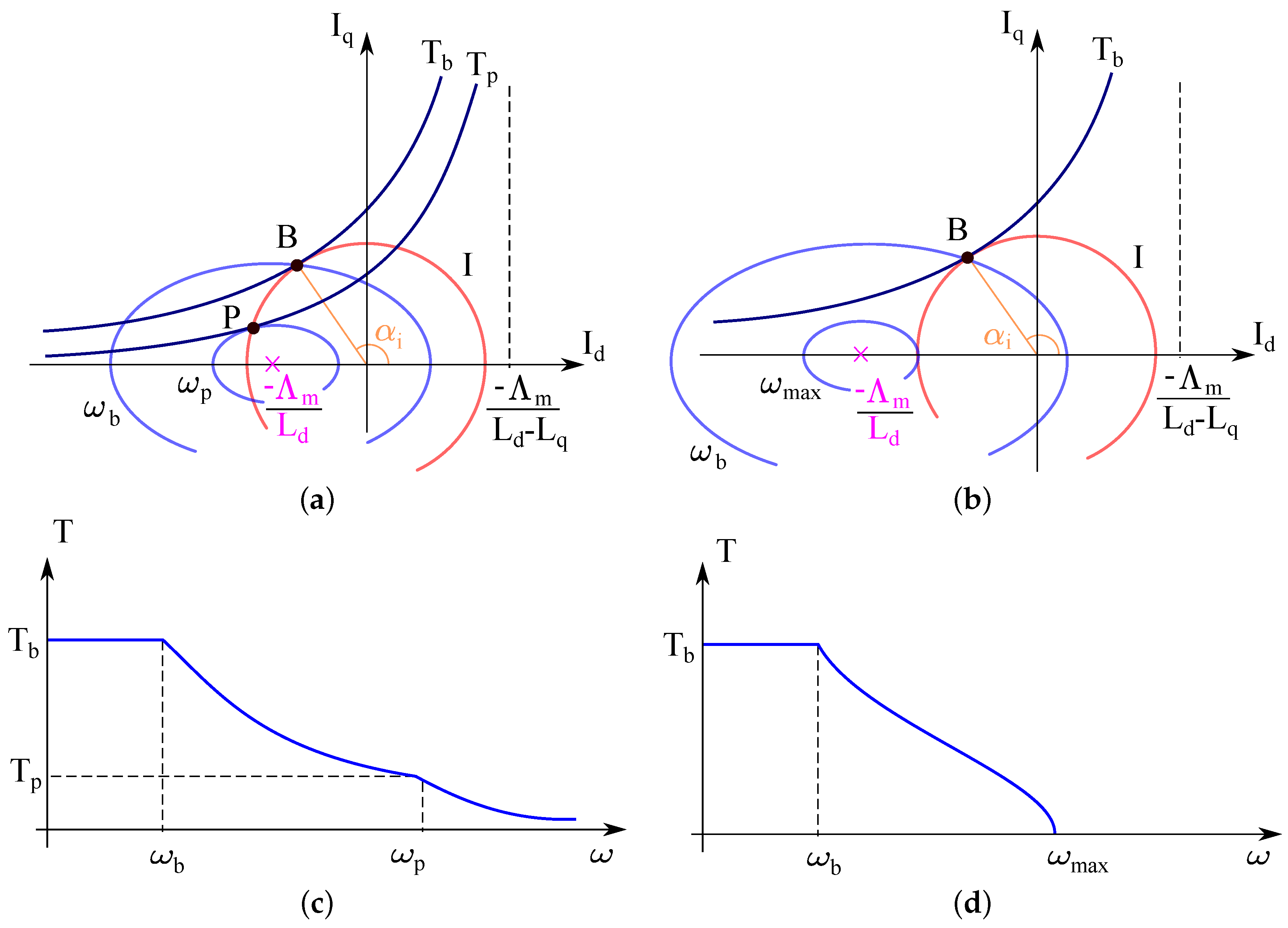
Operating motor conditions are studied by drawing Equations (1) and (2) in the dq current plane as in Figure 2a,b [17,18]. Before analyzing the motor operating regions, some relevant curves are introduced in the dq plane, in particular the current limit locus, the voltage limit loci and the constant torque loci. The motor current limit describes a circle centered in the origin in the dq plane, given by:
I N 2 = I d 2 + I q 2 ,
where I N is the nominal current of the motor. The current limit is represented by a red solid line in Figure 2a,b.
The voltage limit is retrieved from (1), by imposing a maximum voltage magnitude equal to the nominal value V N . The resulting equation describes elliptical trajectories in the dq current plane, which depend on the actual motor speed as:
V N 2 = ω 2 [ ( Λ m + L d I d ) 2 + ( L q I q ) 2 ] .
The curve ellipticity is equal to the motor saliency ratio ξ = L q / L d . Moreover, the ellipses are centered in ( Λ m / L d , 0 ) , where the ratio Λ m / L d is equal to the magnitude of the steady-state three-phase short-circuit current. Furthermore, the ellipse major semi-axis length is equal to V N / ( ω L d ) , thus it is inversely proportional to the operating speed. As limit cases, the voltage limit curves of SPM machines are circular, having an unitary saliency ratio, whereas voltage ellipses of REL motors are centered in the origin, having a zero steady-state short-circuit current. Voltage limit curves are depicted by blue solid line in Figure 2a,b. It is remarked that (4) holds at high speeds and for medium-high power machines. In fact, the resistive voltage drop is not negligible for low power motors and it has to be accounted in the machine description, as in [19].
The constant torque loci shape is obtained by inspecting (2). In particular, constant torque curves are described by hyperbola, whose asymptotes are the d axis and the vertical straight line defined by the equation I d = Λ m / ( L d L q ) . Since the d axis is assumed to be aligned with the PM flux, the vertical asymptote lies in the positive I d semiplane, indeed L d < L q .
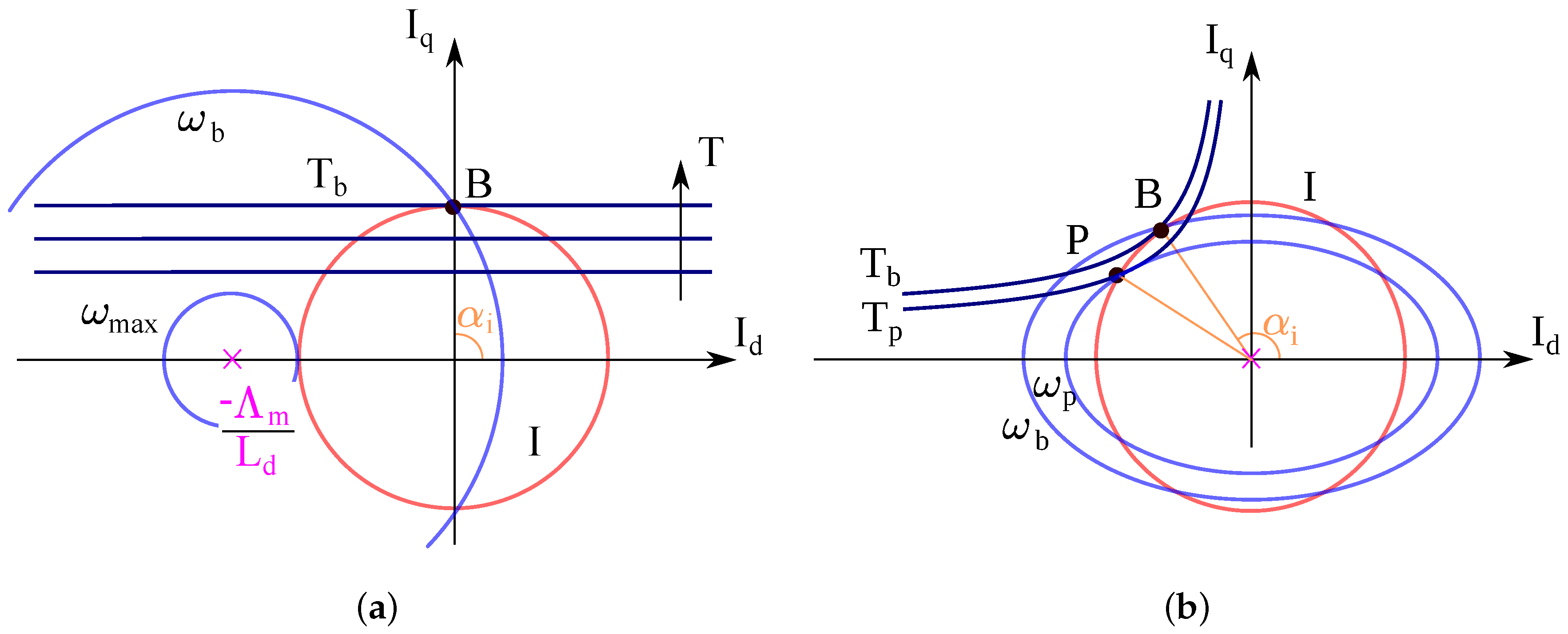
Constant torque loci are the black solid line hyperbolas in Figure 2a,b. As particular case, SPM motors are characterized by horizontal straight lines constant loci as in Figure 3a, having an unitary saliency ratio, whereas REL machines are characterized by hyperbolic constant torque curves centered in the origin, mounting no PMs (Figure 3b.)

2.1. Constant Maximum Available Torque Region

At the standstill condition, the only constraint that limits the motor torque capabilities is the current limit circle (3). The voltage ellipse constraint described by (4) expands, covering the entire dq current plane. Indeed, the ellipse size is inversely proportional to the speed. In this condition, the motor is controlled along the MTPA strategy. In particular, given a desired torque T, the dq currents magnitude I and phase α i are computed such that the desired torque is guaranteed and the Joule losses in the machine are minimized. For any current amplitude, the current angle α i should be chosen equal to:
cos α i = Λ m + Λ m 2 + 8 ( L d L q ) 2 I 2 4 ( L d L q ) I .
Considering Figure 2a,b, the MTPA trajectory is obtained as the tangent points between current circles and torque hyperbola. The maximum available torque is retrieved from (5) by substituting the nominal current magnitude I N , and it represents the nominal motor torque.
The nominal torque remains the maximum available one until the voltage constraint ellipse, which shrinks for increasing speeds, crosses the MTPA current locus at the nominal current circle. This condition occurs in the points denoted as B in Figure 2a,b. Above such a speed, known as nominal speed and denoted as ω b , the motor is not longer able to deliver its nominal torque, since the voltage ellipse constraint forces the working point to lie on a lower torque hyperbola, given the nominal current [20].

2.2. Flux-Weakening: Constant Maximum Available Volt-Ampere Region

FW operation begins above the nominal speed [21]. Since the MTPA strategy can not be implemented, the nominal torque can not be obtained. The maximum available torque for a given speed and a rated current is retrieved by the intersection of the current limit circle with the voltage limit ellipse. This intersection starts moving the working points from the base ones B (Figure 2a,b) along the limit circle towards the point ( I N , 0 ) , keeping a constant Volt-Ampere rating.
Two main possibilities can occur while moving along the current limit circle, depending on the position of the voltage ellipse center with respect to the nominal motor current. If the ratio Λ m / L d is greater than the nominal current I N , the ellipse center lies outside the current limit circle. In this condition, the movement of the motor current along the current limit circle can proceed till the point ( I N , 0 ) , where the motor exhibits zero torque. From a geometrical point of view, it implies that the ellipse voltage limit is tangent to the current limit circle. This condition is depicted in Figure 2b and it corresponds to the smallest voltage ellipse. Moreover, in this condition the voltage limit corresponds to a higher achievable speed:
ω m a x = V N Λ m L d I N .
The motor is not able to operate above such speed, since there are no longer intersections between the current limit and voltage limit locus. In other words, the electric drive has a maximum operating speed. This behavior is often retrieved in SPM machines, characterized by small synchronous inductances and, consequently, high Λ m / L d ratios, as shown in Figure 3a.
On the contrary, a different behavior characterizes machines with the ellipse voltage limit center placed inside the current limit circle. The behavior is shown in Figure 2a. In this case, the movement of the current point along the limit circle reaches the point P in the same figure, where the torque hyperbola is tangent to the voltage limit ellipse. In this operating point P, the drive exhibits its maximum torque-to-voltage ratio and the corresponding electrical speed ω p represents the maximum speed of the FW constant volt-ampere region. Above such speed the control strategy needs to be changed to guarantee a feasible working condition.

2.3. Flux-Weakening: Decreasing Volt-Ampere Region

The third operating region exists only for those machines whose ellipse center lies within the current circle, as in Figure 2a. This is also the case of REL motor [18,22] whose circle diagram is reported in Figure 3b. SPM machines achieve rarely such operating mode, if not supported by external inductances. Above the speed ω p , torque performances are limited by the voltage limit ellipse. In particular, it is not possible to proceed moving the current along the current limit circle. The maximum drive current must decreased in order to respect the voltage limit ellipse, describing the Maximum Torque per Voltage (MTPV) trajectory as reported in Figure 2c. Since the ellipse axis is inversely proportional to the speed, the drive can theoretically reach an infinite maximum speed, i.e., till the ellipse collapses in a single point. Of course, mechanical effects limit the maximum achievable speed operation.

3. Design of Electric Motors for Given FW Requirements

Synchronous motor type and inverter Volt-Ampere ratings can be selected to meet a desired torque versus speed characteristic. Alternatively, the motor drive design can be optimized for a given nominal and FW requirement as proposed in [23]. This allows both the energy losses and the constraints on the power converter to be reduced. A proper combination of machine parameters of rotor PM and excitation flux linkage can be derived, in particular d- and q-axis inductances. The inverter current rating can be obtained, as well.
For the sake of generality, the design is carried out using normalized motor data, as defined in Appendix A. Normalized quantities are denoted by lower case letters whereas uppercase letters refers to actual quantities.
The flux linkage, the d q -axis inductances and the inverter Volt-Ampere ratings are selected such that the drive exhibits the desired nominal torque T b at the desired base speed Ω b . Moreover, the maximum p.u. speed and p.u. torque achievable in FW operating condition are defined, namely ω f w and t f w . They represent the maximum FW speed and torque for which the motor is designed, respectively. The motor has to guarantee all requirements in its operating conditions.
The design procedure works as follows:
1.
Set the desired values of maximum FW speed ω f w and torque t f w ;
2.
A suitable couple of rotor flux linkage λ r and saliency ratio ξ must be selected;
3.
In order to fulfill the specification at nominal point of base torque t b = 1 , voltage v = 1 , and speed ω b = 1 , only one value of direct inductance l d and current i can assure the desired performance once λ r and ξ are set;
4.
Finally, the defined p.u. parameters can be reported to the absolute magnitude value and then the machine can be designed. These values must be realized with a proper motor design by taking into account practical limitation.
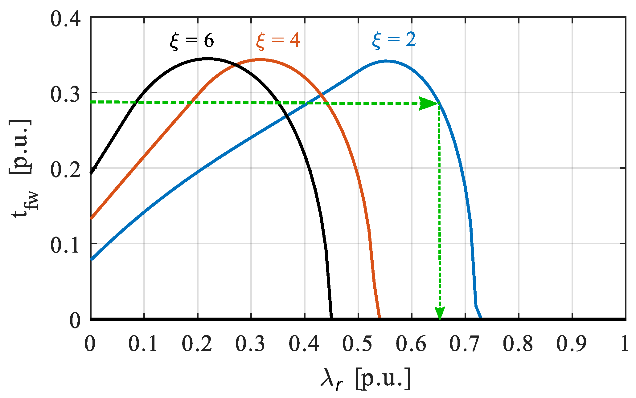
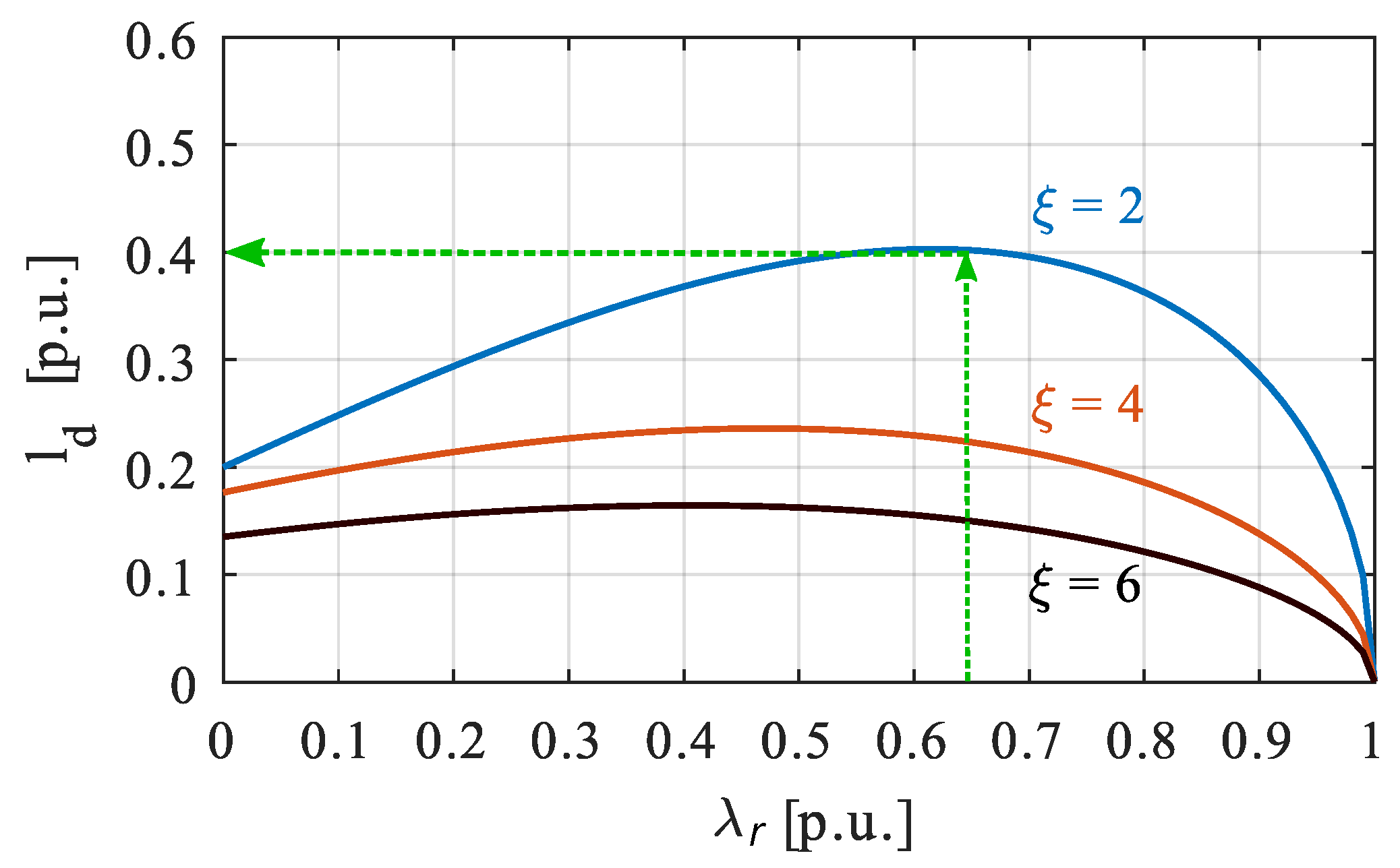
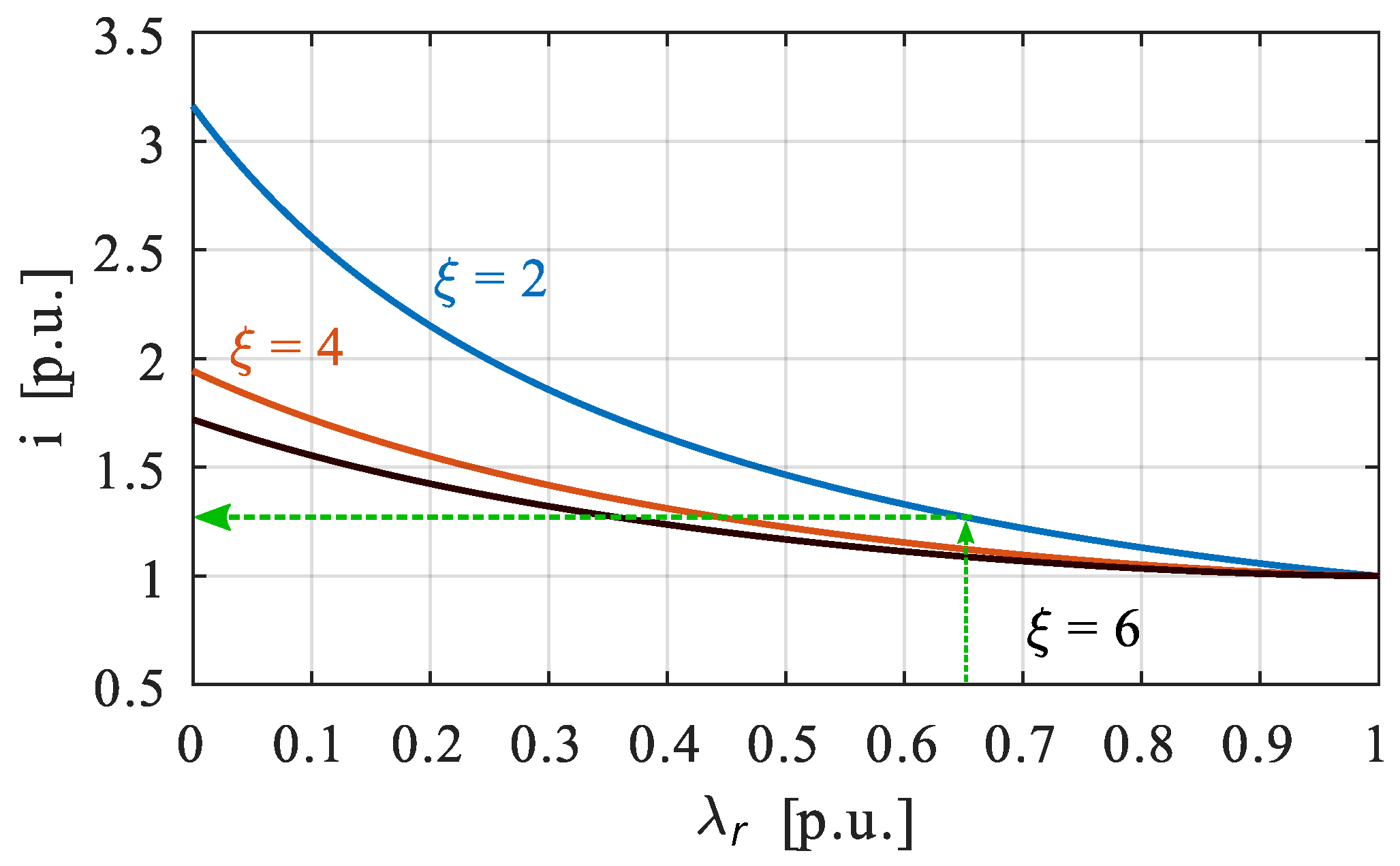
An example is reported in Figure 4, considering a desired FW speed ω f w = 4 p.u. The requirement on FW torque t f w at speed ω f w = 4 p.u. is 0.28 p.u. If ξ = 2 is defined, λ r has to be chosen equal to 0.65 , accordingly to the green line in Figure 4. Once values of λ r and ξ are selected, the values of l d and i can be grabbed by exploiting Figure 5 and Figure 6. With the selected values, l d = 0.4 p.u. and i = 1.3 p.u. It is worth noting that Figure 4 shows that the FW torque t f w does not exist at a desired speed for all couple of the rotor flux linkage λ r and saliency ratio ξ . Moreover, there is only one peak for each saliency ratio ξ .

3.1. PM Motors

In PM motors, the rotor flux linkage λ r is equal to λ m and it can change in the range between 0 and 1. Comparing Figure 4, Figure 5 and Figure 6, the maximum torque occurs with λ m = l d i , or when the voltage limit ellipse center is exactly placed on the current limit circle. The corresponding maximum power is approximately equal to 2 p.u., i.e., the theoretical value when ω f w = . A wide FW speed range can also be obtained with a lower ξ , provided that high inductances or additional external inductances are used. Moreover, comparing the FW torque in Figure 4 with the current values in Figure 6, it is always preferable to design synchronous motors with λ r > l d i to minimize the losses. As far as joule losses are concerned, PM motors should be preferred rather than REL motors. Other examples of IPM design are reported in [25].
In case of SPM motors, the problem can be solved analytically, namely, l d and i can be computed in closed form. This kind of motors have been studied in [26,27,28,29]. A SPM motor is characterized by a unitary saliency ratio ξ . In addition, it is worth reminding that the MTPA locus corresponds to a current angle α i = 90 degrees. By fixing t b = 1 p.u., v = 1 p.u., ω b = 1 p.u., and α i = 90 degrees, the motor inductance and the drive current result as [24]:
l d = l q = λ m 1 λ m 2 , i = 1 λ m .
Then, the maximum FW speed can be evaluated as:
ω m a x = 1 λ m 1 λ m 2 .
All speeds ω f w can be reached, even if high values of current or inductances may be required for the highest speed. Since high inductances are not obtained with an SPM motor configuration, a wide FW speed range requires the use of external inductances.

3.2. Pure Reluctance Motor

In REL motors, the rotor flux linkage λ r is zero. Thus, the MTPA angle is α i = 135 degrees (with the adopted convention l q > l d ). The normalized values of the d q -axis inductances and drive current can be expressed analytically as a function of the motor saliency ratio ξ as follow:
l d = ξ 1 ξ 2 + 1 i = 2 ( ξ 2 + 1 ) ξ 1
which is always greater than 2 .
As regards the FW performance, the torque is always greater than zero at any speed ω f w [30,31,32]. However, both the maximum torque and power decrease with ω f w , while for an IPM motor the maximum power can be kept constant, close to 2 .

3.3. Motor with Rotor Excitation Windings

Power generation and traction systems use motors with excitation windings. In these machines, the rotor flux linkage λ r is given by the sum of PM λ m and excitation λ e flux linkages. The control of excitation current gives an additional degree of freedom that can improve the motor performance at high speeds. The formulation proposed in [33]:
λ r * = ξ ( ω f w l d i ) 2 + v 2 ω f w ( ω f w ξ l d i ) 2 + v 2
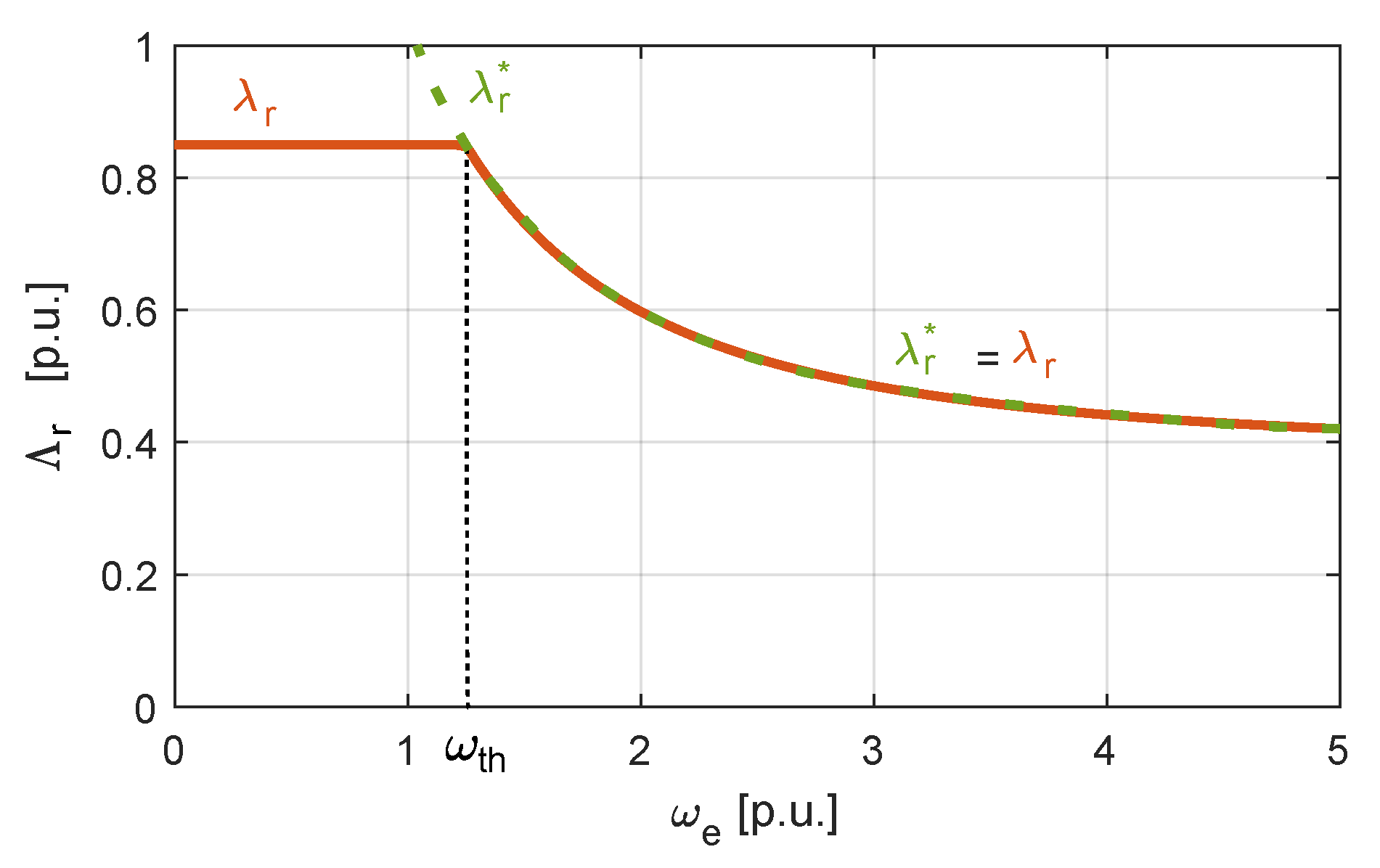
computes the rotor flux linkage λ r * that maximizes the delivered motor torque at each motor speed. In order to keep the power constant, its value increases as the motor speed decreases. However, to guarantee the nominal motor behavior, the actual rotor flux linkage λ r must be limited to its base point value. Figure 7 shows an example of the rotor flux linkage trend as a function of motor speed with a rotor flux linkage at base point of λ r = 0.85 p.u. The rotor flux linkage is constant and equal to its base value for motor speed smaller than ω t h . For higher speed, the excitation flux linkage λ e decreases to assure a total rotor flux linkage equal to λ r * . The speed ω t h is the threshold speed at which excitation must decreases. It is worth noting that ω t h is greater than unity indeed stator currents are already flux-weakening the machine when the excitation flux linkage λ e start decreasing. During that FW operations, the rotor flux λ h e and the corresponding stator current are regulated so as to achieve a torque as high as possible according to that speed ω f w . For different values of λ r , ξ , l d , i N and v N , it is possible to verify that the reduction of rotor flux is convenient only if λ r > l d i d as described in [33,34]. Similarly to Figure 4, Figure 8 shows the FW torque at ω f w = 4 p.u. for different values of λ r in a HEPM motor, considering the strategy of rotor flux linkage reduction as in (10). The maximum delivered torque by the machine at speed ω f w = 4 p.u. is represented as a function of the rotor flux linkage at base point that changes from 0 to 1 p.u. Motor with an excited rotor allows for operating at high speed, e.g., ω f w = 4 p.u., even if the base rotor flux linkage is high as in the aforementioned example. This is a important difference with respect to classical motor configuration where a trade-off between rotor flux linkage magnitude and maximum achievable speed must be found (see Figure 4). This difference allows for reducing the base motor current and, in turn, the motor losses.
The motor design procedure is the same already described in Section 3. The ratio between λ e and λ m must be defined and it can be chosen according to the machine application. The described strategy can be applied in HEPM and WRSM motor configurations. It was compared to conventional IPM motors in terms of torque, speed capabilities and efficiency in [35,36,37,38,39].

4. Flux-Weakening Control Strategies

FW operation of synchronous motors has been investigated for all the most widespread control architectures, including current controllers, flux-based controllers and model predictive control schemes. All these three structures are considered in this review. More attention is paid on FW operation with synchronous PI current regulators, since it is by far the most common solution. FW control strategies are clustered according to the presence or absence of a feedback of the motor voltage. Actually, the feedback is obtained by using the inverter reference voltage, since the actual motor voltage is not available in industrial drives. According to the voltage feedback criterion, three main categories of FW strategies are identified:
  • feed-forward architectures, which do not implement any voltage feedback;
  • feedback schemes, where only a voltage feedback provides the FW operation;
  • hybrid methods, which couple both a voltage feedback and feed-forward action.
All these topologies have been deeply investigated in the literature and each of them has its own benefits. In the following, each category is reviewed, considering first drives which implement synchronous current PIs.

4.1. Feed-Forward Schemes

Feed-forward schemes are known also as model-based methods. In fact, this technique consists of computing the FW d-axis current reference by exploiting an accurate analytical model of the motor, e.g., the voltage balance equation as in [17]. A block scheme representation of feed-forward structures is reported in Figure 9, including some aspects that may be taken into consideration when the feed-forward term is computed. The required inputs by the algorithm are the torque reference, which comes from a speed regulator, the motor speed and all the electric motor parameters, i.e., the stator windings resistance and, possibly, the current to flux linkages relationship [22]. All the asterisks in Figure 9 denote reference variables. The same notation is used hereinafter.
The most relevant advantage of this approach is a superior behavior during fast transients. Indeed, the dynamic performances of feedback type schemes are slow down by the closed-loop dynamic of the voltage loop. Moreover, as further merits, feed-forward methods are not affected by significant stability problems [40] and no tuning parameters are necessary.
However, a pure open-loop computation of the FW current reference can be badly affected by any parameter mismatch. Since FW operation is often required in demanding applications, such as the automotive, the parameter sensitivity issue needs to be addressed. Most of the works on feed-forward schemes of the last two decades aim to overcome this problem. In particular, the temperature effect on the stator resistance and the nonlinear magnetic characteristic have been deeply analyzed.
In [41], the iron saturation effect is addressed by an online estimation of the electric motor inductive parameters. The paper focuses on an IPM machine, but the method can be easily implemented for other highly saturated motor topologies, e.g., pure REL machines or PM assisted REL motors. However, the work neglects the effect of the stator resistance.
The latter is studied in [42], where the stator resistance is included in the computation of the current set points during the FW operation. Moreover, the computational burden of the scheme is reduced by approximating the elliptical voltage constraint in a piece-wise linear manner. The latter method appears indeed as the benchmark for feed-forward solutions. Look-up-tables may be too small because of hardware limitations. In this case, advanced computational tools are available to expand small tables to larger ones, such as the second-order bilinear interpolation method [43]. More and more detailed model [44] may be implemented in order to improve the current reference generation. For example, the inverter nonlinear voltage drop are included in [9], too. However, the computation burden increases with the complexity of the model. Thus, the main advantages of the feed-forward architecture is its simplicity. When the model becomes too cumbersome, it is convenient to prefer feedback-based solutions. Despite all the improvements, it is worth reminding also that the available DC-bus of the inverter is rarely entirely exploited by feed-forward algorithms, since a small derating needs to be introduced to deal with the parameter sensitivity issue.

4.2. Feedback Schemes

Feedback schemes [45,46] implement a feedback on the inverter reference voltages to reach the FW operation. This topology is also known as robust, to further highlight the key benefit with respect to feed-forward architectures. The plant model is not explicitly exploited by feedback algorithms. However, the electric model is required for tuning the voltage loop regulator. In addition, an accurate model knowledge results mandatory to linearise the loop, as will be clear in the following. The two merits of the feedback solutions are the enhanced parametric robustness and a higher exploitation of the available inverter DC-bus voltage. However, the voltage control loop introduces a delay in the FW response. Thus, dynamic performances are slightly penalized. Moreover, the additional control loop poses many challenges, e.g., tuning, linearisation and selection of a reasonable bandwidth.
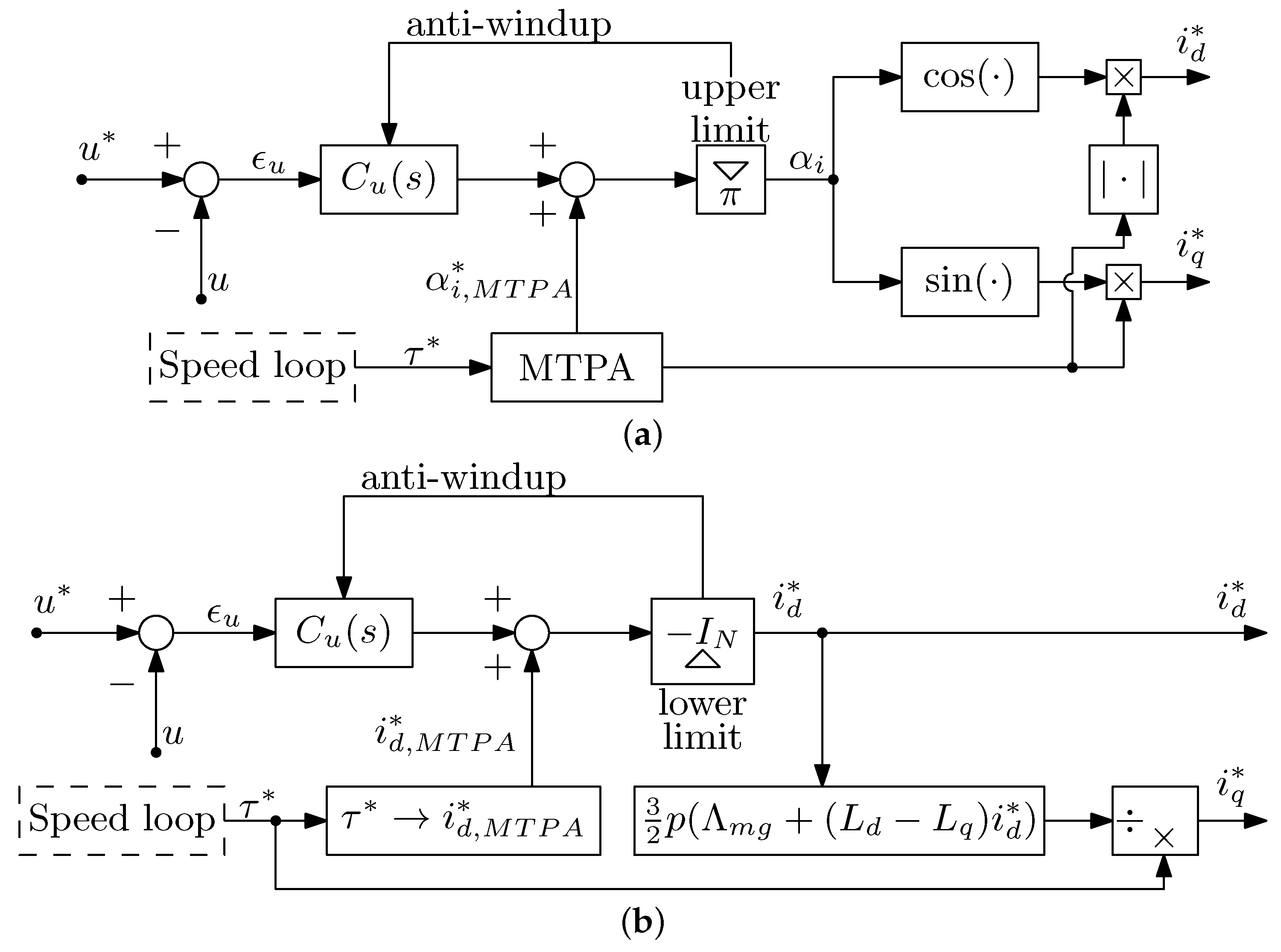
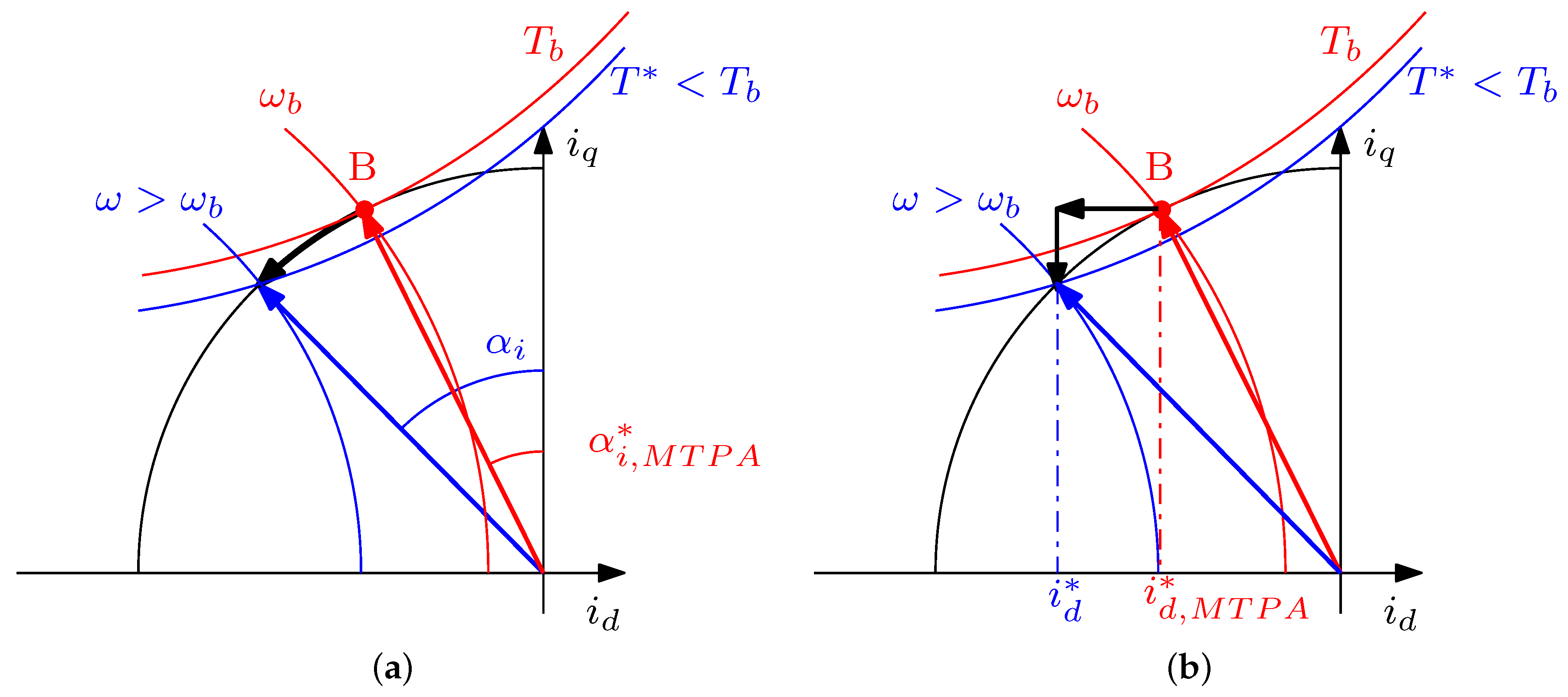
Feedback topologies are subdivided in two subcategories, depending on how the loop acts on the current references coming from the speed loop. In particular, it is possible to distinguish between solutions acting on the angle of the MTPA current references [47,48] and solutions acting on the d-current reference [49,50]. The control schemes are reported in Figure 10 whereas their operating principle is depicted in Figure 11. The two different approaches affect both control effectiveness and regulator tuning. It is worth noting that the voltage loop linearization deeply differs between the two schemes.
An interesting configuration was proposed in [51] where the voltage error generates two auxiliary control variables. The former acts on the MTPA current reference angle, increasing the FW current component. The latter is used when the current amplitude needs to be limited if the MTPV operation is reached. The voltage loop is often designed in a model-based fashion to accomplish the desired specifications in terms of bandwidth and phase margin. Alternatively, the tuning can be performed using a modified relay feedback tuning, as proposed in [52]. This method represents a promising solution for general purpose applications, where motor parameters are partially or completely unknown and an online auto-tuning procedure is needed.
Unfortunately, the dynamic of the current angle is strongly nonlinear. Moreover, a linearization of the angle loop would require the computation of a non trivial linearizing gain. From this point of view, the d-axis current strategy appears more convenient [53]. The loop linearization requires an accurate knowledge of the electric motor model and system parameters and the operating speed as auxiliary input of the voltage loop.
Feedback based strategies are adopted for HEPM motors [54], as well. However, the voltage loop is used to regulate the rotor excitation current, instead of the d-axis stator windings current. This is still an open research topic since new motor topologies combining PM and current winding to generate the rotor flux linkage have been proposed. Different hybridization ratio leads to an additional degree of freedom in the control that it can be exploited. Moreover, in HEPM motors, the excitation current affects the motor voltage equation than the linearization approach [53] is no longer valid and a different dissertation must be studied.
Particular attention needs to be paid to avoid the wind-up phenomenon in the voltage loop. Thus, a back-calculation anti-windup strategy is proposed in [55]. As a further relevant contribution, the same paper proposes an adaptive velocity particle swarm optimization algorithm to optimize the control parameters of the anti-windup proportional and integral controller. Once the desired architecture is selected, a proper bandwidth of the voltage loop needs to be chosen. In case of d-axis current compensation schemes, shown in Figure 10b, three different approaches are proposed in [40]. In a nutshell, the bandwidth can be selected based on specifications of torque disturbance transients, fast acceleration transients or quick variation of the grid voltage.

4.3. Hybrid FW Schemes

Finally, mixed or hybrid FW schemes are shortly reviewed. Hybrid architectures include both a voltage control loop and a feed-forward term. As feed-forward schemes, the feed-forward contribute is computed by means of the motor model. As feedback structures, the reference d-axis current or current angle is then modified accordingly to the output of the voltage loop.
This allows us to reinforce the feed-forward action. Not surprisingly, mixed schemes aim to guarantee the benefits of both aforementioned structures, namely, fast dynamic and robustness against parameter variations. Examples of hybrid FW schemes can be found in [56,57,58].

4.4. DC-Bus Voltage Use

Before moving towards FW operation of motors which implement flux controllers, it is worth mentioning another key research topic, i.e., the effective usage of the inverter DC-bus voltage [59,60]. In fact, when the motor operates at high speed, the inverter works close to its intrinsic voltage constraints. In particular, voltage magnitudes are clamped to the value V DC / 3 if the space vector modulation (SVM) method is implemented in the converter. However, it is possible to go beyond this limit, approaching the six-step operation [61]. Sul et al. proposes a FW method able to achieve a quasi six-step operation [62], synthesizing voltage vectors with an amplitude up to 2 V DC π . This FW method requires a proper design of the current regulators. Nevertheless, this technique allows for a higher torque and power performances, together with a lower current ripple.

4.5. Direct Flux Control

FW operation has been investigated for drives which directly control the motor flux linkages [63], instead of the d and q axis current. These architectures require a stator flux observer, too. Among these methods, the direct flux FOC and the DTC [64] are considered. Concerning the first topology, a FW strategy is presented in [11], which implements a simple feed-forward strategy. The IPM motor flux is decreased linearly with the operating speed. Since the drive is fed by a battery on an electric scooter, the flux is regulated proportionally to the feeding battery voltage. DTC schemes behave in a more robust manner with respect to parametric uncertainties, as described in [65]. In the aforementioned work, the DTC is coupled with a model-based feed-forward FW strategy. A simplified control scheme is reported in Figure 12. The resulting scheme is compared with the benchmark current regulators coupled with feed-forward and feedback FW strategies. The DTC exhibits promising results even in presence of parameter variation, simplicity of calculation, and stable control.
For sake of completeness, it is reminded that the DTC can be coupled even with pseudo-feedback FW methods, as in [66]. The proposed technique reduces the flux linkage reference and adjusts the torque reference when the required torque is not achieved. Even if the voltage loop is not present, the flux linkage reference is adjusted based on a measured error rather than the computation of a pure open-loop reference. Furthermore, the FW strategy does not require explicitly motor model parameters. For these two reasons, the technique is categorized as a feedback-type.

4.6. Model Predictive Control

An emerging and promising control structure in electric motor drives is represented by the model predictive control. Few preliminary works are found in the literature concerning the FW operation, e.g., [67], resulting an appealing topic for academic research. Model predictive control is mostly used to replace the d- and q-axis current regulators, rather than acting on the generation of the FW current references as in [68]. The d-axis FW current reference is generated by a standard feed–forward algorithm, whereas the model predictive control takes care of the current reference tracking, as shown in Figure 13. A model predictive control is designed for the voltage control loop of a feedback strategy in [69]. The authors believe that the complexity and non linearity of the problems have not entirely been addressed yet.

4.7. Sensorless Control

Nowadays, a crucial requirements for industrial drives is the sensorless operation capability. In other words, the motor needs to be controlled without the position sensor to increase the reliability of the system and to reduce the product costs. Interesting and challenging issues occur when a drive operates in the FW region without position sensor. For example, the delay introduced by position estimation algorithms could influence FW loops. Indeed, a Luenberger observer is proposed in [70] to replace the low-pass filter in the rotor position estimation. Thanks to the proposed observer, the motor speed estimation delay was reduced. The delay can be further reduced by means of even more sophisticated position estimators, such as the extended Kalman filter [71]. However, attention must be taken to keep the computation burden at bay when coupling a voltage loop, a position observer and, possibly, current-flux linkage look-up tables.
Instability problems of sensorless FW operation are analyzed recently in [72], considering both feedback and feed-forward strategies. In particular, it has been analytically proven that the limited bandwidth of the position estimation can induce speed oscillations, which increase when approaching the FW operation. The system may even become unstable. This is mainly due to the position estimation error and it is worsened in fast transients. Thus, from this point of view, low-inertia drives result to be particularly challenging.

5. Conclusions

The flux-weakening operation of synchronous motor is used for guaranteeing a constant power range and for increasing the operation region. Machine design and control strategies have to take into account the possibility to work in that condition.
The p.u. analysis has been reported considering the design of all the possible PMSMs, focusing the attention on the HEPM and WRSM motors that has been rediscovered in the recent years. These machines have been investigated in the literature. They show a wide speed range with constant unit power factor along the FW region. Three kinds of control algorithms have been proposed with their own advantages and disadvantages. The presented architectures include: feed-forward architectures, which do not implement any voltage feedback; feedback schemes, where only a voltage feedback provides the FW operation; hybrid methods, which couple both a voltage feedback and feed-forward action. These controls have been compared in term of robustness, computational cost and dynamic response.
Robustness to parameter variation and model uncertainties is a flaw in the feed-forward method as it works in open-loop manner. It assumes a perfect motor model and parameters knowledge, thus any parameter variation or inaccuracy in the motor model affects the controller performance. The other two methods, which are feed-back based, are inherently robuster to such uncertainties.
The perspectives and judgments on that field are of considerable interest. An effective exploitation of the constant power region is increasingly required in various applications, so FW operation is mandatory. As illustrated in this review, the problem has to be addressed from both the machine design and the control point of view. Hybrid excited and wounded rotor machine exhibit outstanding FW performance. Their rediscovery for this application is quite recent and it is still an open research topic. On the other hand, FW schemes still need in-depth study. The process is highly nonlinear; therefore, its description and control are not trivial as well as the controller tuning. The inherent feature of MPC in handling multi-input multi-output nonlinear systems makes this control strategy an attractive solution. Finally, the interaction of several control loops poses several control challenges and this is an open issue that characterize FW and sensorless control schemes.

Author Contributions

Equal contribution by the Authors. All authors have read and agreed to the published version of the manuscript.

Funding

This research received no external funding.

Conflicts of Interest

The authors declare no conflict of interest.

Appendix A. Normalized Parameters

For the sake of generality, it is convenient to normalize all motor data with respect to the base quantities defined in the following. Normalised data are denoted by means of small letters. This permits to easily extend the considerations to motors of any power. Moreover, interesting comparisons can be carried out among different motor types, requiring fixed FW performances.
Torque, speed, and voltage under full load at the maximum speed of the constant torque region have been defined as base torque T b , base angular frequency Ω b and base voltage V N , respectively. The base values of the motor parameters and current are retrieved by using the power balance:
T b Ω b p = 3 2 V N I N .
Then, the base current, inductance and flux linkage are computed as:
I N = 2 T b Ω b 3 p V N , L b = 3 p V N 2 2 T b Ω b 2 , Λ b = L b I N = V N Ω b .
All the normalised motor data are resumed in Table A1.
Table A1. Normalised quantities.
P.U. QUANTITIES
Torque t = T / T b Electrical speed ω = Ω / Ω b
Phase current i = I / I N Rotor flux linkage λ r b = ( Λ m + Λ e ) / Λ b
Phase voltage v = V / V N Synchronous inductance l = L / L b

References

  1. Soong, W.; Miller, T. Practical field-weakening performance of the five classes of brushless synchronous AC motor drive. In Proceedings of the 1993 Fifth European Conference on Power Electronics and Applications, Brighton, UK, 13–16 September 1993; Volume 5, pp. 303–310. [Google Scholar]
  2. Sebastiangordon, T.; Slemon, G.R. Operating Limits of Inverter-Driven Permanent Magnet Motor Drives. IEEE Trans. Ind. Appl. 1987, IA-23, 327–333. [Google Scholar] [CrossRef]
  3. Fontana, M.; Bianchi, N. Design and Analysis of Normal Saliency IPM Spoke Motor. IEEE Trans. Ind. Appl. 2020, 56, 3625–3635. [Google Scholar] [CrossRef]
  4. Amara, Y.; Vido, L.; Gabsi, M.; Hoang, E.; Ben Ahmed, A.H.; Lecrivain, M. Hybrid Excitation Synchronous Machines: Energy-Efficient Solution for Vehicles Propulsion. IEEE Trans. Emergy Sel. Top. Power Electron. 2009, 58, 2137–2149. [Google Scholar] [CrossRef]
  5. Sneyers, B.; Novotny, D.W.; Lipo, T.A. Field Weakening in Buried Permanent Magnet AC Motor Drives. IEEE Trans. Ind. Appl. IA-21, 398–407. [CrossRef]
  6. Jahns, T.M.; Kliman, G.B.; Neumann, T.W. Interior Permanent-Magnet Synchronous Motors for Adjustable-Speed Drives. IEEE Trans. Ind. Appl. 1986, IA-22, 738–747. [Google Scholar] [CrossRef]
  7. Jahns, T.M. Flux-Weakening Regime Operation of an Interior Permanent-Magnet Synchronous Motor Drive. IEEE Trans. Ind. Appl. 1987, IA-23, 681–689. [Google Scholar] [CrossRef]
  8. Sepulchre, L.; Fadel, M.; Pietrzak-David, M.; Porte, G. MTPV Flux-Weakening Strategy for PMSM High Speed Drive. IEEE Trans. Ind. Appl. 2018, 54, 6081–6089. [Google Scholar] [CrossRef]
  9. Xia, Z.; Nalakath, S.; Tarvirdilu-Asl, R.; Sun, Y.; Wiseman, J.; Emadi, A. Online Optimal Tracking Method for Interior Permanent Magnet Machines With Improved MTPA and MTPV in Whole Speed and Torque Ranges. IEEE Trans. Power Electron. 2020, 35, 9753–9769. [Google Scholar] [CrossRef]
  10. Xu, L.; Ye, L.; Zhen, L.; El-Antably, A. A new design concept of permanent magnet machine for flux weakening operation. IEEE Trans. Ind. Appl. 1995, 31, 373–378. [Google Scholar] [CrossRef] [Green Version]
  11. Pellegrino, G.; Armando, E.; Guglielmi, P. Direct Flux Field-Oriented Control of IPM Drives With Variable DC Link in the Field-Weakening Region. IEEE Trans. Ind. Appl. 2009, 45, 1619–1627. [Google Scholar] [CrossRef]
  12. Toso, F.; Carlet, P.G.; Preindl, M.; Bolognani, S. Active-Flux-Based Motion-Sensorless Control of PMSM Using Moving Horizon Estimator. In Proceedings of the 2018 IEEE 9th International Symposium on Sensorless Control for Electrical Drives (SLED), Helsinki, Finland, 13–14 September 2018; pp. 78–83. [Google Scholar] [CrossRef]
  13. Favato, A.; Carlet, P.G.; Toso, F.; Torchio, R.; Bolognani, S. Integral Model Predictive Current Control for Synchronous Motor Drives. IEEE Trans. Power Electron. 2021, 36, 13293–13303. [Google Scholar] [CrossRef]
  14. Ortombina, L.; Karamanakos, P.; Zigliotto, M. Robustness Analysis of Long-Horizon Direct Model Predictive Control: Permanent Magnet Synchronous Motor Drives. In Proceedings of the 2020 IEEE 21st Workshop on Control and Modeling for Power Electronics (COMPEL), Aalborg, Denmark, 9–12 November 2020; pp. 1–8. [Google Scholar] [CrossRef]
  15. Dianov, A.; Tinazzi, F.; Calligaro, S.; Bolognani, S. Review and Classification of MTPA Control Algorithms for Synchronous Motors. IEEE Trans. Power Electron. 2022, 37, 3990–4007. [Google Scholar] [CrossRef]
  16. Yamazaki, K.; Seto, Y. Iron loss analysis of interior permanent-magnet synchronous motors-variation of main loss factors due to driving condition. IEEE Trans. Ind. Appl. 2006, 42, 1045–1052. [Google Scholar] [CrossRef]
  17. Morimoto, S.; Takeda, Y.; Hirasa, T.; Taniguchi, K. Expansion of operating limits for permanent magnet motor by current vector control considering inverter capacity. IEEE Trans. Ind. Appl. 1990, 26, 866–871. [Google Scholar] [CrossRef]
  18. Soong, W.; Miller, T. Theoretical limitations to the field-weakening performance of the five classes of brushless synchronous AC motor drive. In Proceedings of the 1993 Sixth International Conference on Electrical Machines and Drives, Oxford, UK, 8–10 September 1993; pp. 127–132. [Google Scholar]
  19. Hackl, C.M.; Kullick, J.; Eldeeb, H.; Horlbeck, L. Analytical computation of the optimal reference currents for MTPC/MTPA, MTPV and MTPF operation of anisotropic synchronous machines considering stator resistance and mutual inductance. In Proceedings of the 2017 19th European Conference on Power Electronics and Applications (EPE’17 ECCE Europe), Warsaw, Poland, 11–14 September 2017; pp. P.1–P.10. [Google Scholar] [CrossRef]
  20. Adnanes, A.; Undeland, T. Optimum torque performance in PMSM drives above rated speed. In Proceedings of the Conference Record of the 1991 IEEE Industry Applications Society Annual Meeting, Dearborn, MI, USA, 28 September–4 October 1991; Volume 1, pp. 169–175. [Google Scholar] [CrossRef]
  21. Schiferl, R.; Lipo, T. Power capability of salient pole permanent magnet synchronous motors in variable speed drive applications. IEEE Trans. Ind. Appl. 1990, 26, 115–123. [Google Scholar] [CrossRef]
  22. Betz, R.; Jovanovic, M.; Lagerquist, R.; Miller, T. Aspects of the control of synchronous reluctance machines including saturation and iron losses. In Proceedings of the Conference Record of the 1992 IEEE Industry Applications Society Annual Meeting, Houston, TX, USA, 4–9 October 1992; Volume 1, pp. 456–463. [Google Scholar] [CrossRef]
  23. Dang, L.; Bernard, N.; Bracikowski, N.; Berthiau, G. Design Optimization with Flux Weakening of High-Speed PMSM for Electrical Vehicle Considering the Driving Cycle. IEEE Trans. Ind. Electron. 2017, 64, 9834–9843. [Google Scholar] [CrossRef]
  24. Bianchi, N.; Bolognani, S. Parameters and volt-ampere ratings of a synchronous motor drive for flux-weakening applications. IEEE Trans. Power Electron. 1997, 12, 895–903. [Google Scholar] [CrossRef]
  25. Bianchi, N.; Bolognani, S. Unified approach to the analysis and design of an AC motor drive for flux-weakening operations. In Proceedings of the Conference Record of 1998 IEEE Industry Applications Conference. Thirty-Third IAS Annual Meeting, St. Louis, MO, USA, 12–15 October 1998; Volume 1, pp. 95–102. [Google Scholar] [CrossRef]
  26. Pellegrino, G.; Vagati, A.; Guglielmi, P.; Boazzo, B. Performance Comparison Between Surface-Mounted and Interior PM Motor Drives for Electric Vehicle Application. IEEE Trans. Ind. Electron. 2012, 59, 803–811. [Google Scholar] [CrossRef] [Green Version]
  27. Bianchi, N.; Bolognani, S.; Frare, P. Design criteria for high-efficiency SPM synchronous motors. IEEE Trans. Energy Convers. 2006, 21, 396–404. [Google Scholar] [CrossRef]
  28. Li, Y.; Bobba, D.; Sarlioglu, B. Design and Optimization of a Novel Dual-Rotor Hybrid PM Machine for Traction Application. IEEE Trans. Ind. Electron. 2018, 65, 1762–1771. [Google Scholar] [CrossRef]
  29. Kawanishi, K.; Matsuo, K.; Mizuno, T.; Yamada, K.; Okitsu, T.; Matsuse, K. Development and Performance of High-Speed SPM Synchronous Machine. In Proceedings of the 2018 International Power Electronics Conference (IPEC-Niigata 2018-ECCE Asia), Niigata, Japan, 20–24 May 2018; pp. 169–176. [Google Scholar] [CrossRef]
  30. Abeyrathne, I.P.; Toulabi, M.S.; Filizadeh, S. Design Optimization and Performance Prediction of Synchronous Reluctance Motors. In Proceedings of the 2018 21st International Conference on Electrical Machines and Systems (ICEMS), Jeju, Kore, 7–10 October 2018; pp. 576–581. [Google Scholar] [CrossRef]
  31. Vagati, A.; Pastorelli, M.; Francheschini, G.; Petrache, S. Design of low-torque-ripple synchronous reluctance motors. IEEE Trans. Ind. Appl. 1998, 34, 758–765. [Google Scholar] [CrossRef]
  32. Morimoto, S.; Ooi, S.; Inoue, Y.; Sanada, M. Experimental Evaluation of a Rare-Earth-Free PMASynRM With Ferrite Magnets for Automotive Applications. IEEE Trans. Ind. Electron. 2014, 61, 5749–5756. [Google Scholar] [CrossRef]
  33. Bianchi, N.; Cinti, L.; Michieletto, D. Hybrid Excitation PM Synchronous Motors: Part I Per Unit Analysis. IEEE Trans. Energy Convers. 2021, 37, 487–494. [Google Scholar] [CrossRef]
  34. Bianchi, N.; Michieletto, D.; Cinti, L. Hybrid Excitation PM Synchronous Motors: Part II—Finite Element Analysis. IEEE Trans. Energy Convers. 2021, 37, 495–504. [Google Scholar] [CrossRef]
  35. Rossi, C.; Casadei, D.; Pilati, A.; Marano, M. Wound Rotor Salient Pole Synchronous Machine Drive for Electric Traction. In Proceedings of the Conference Record of the 2006 IEEE Industry Applications Conference Forty-First IAS Annual Meeting, Tampa, FL, USA, 8–12 October 2006; Volume 3, pp. 1235–1241. [Google Scholar] [CrossRef]
  36. Cinti, L.; Bianchi, N. Hybrid-Excited PM Motor for Electric Vehicle. Energies 2021, 14, 916. [Google Scholar] [CrossRef]
  37. Cinti, L.; Michieletto, D.; Bianchi, N.; Bertoluzzo, M. A Comparison between Hybrid Excitation and Interior Permanent Magnet Motors. In Proceedings of the 2021 IEEE Workshop on Electrical Machines Design, Control and Diagnosis (WEMDCD), Modena, Italy, 8–9 April 2021; pp. 10–15. [Google Scholar] [CrossRef]
  38. Cinti, L.; Carlucci, M.; Bianchi, N.; Bertoluzzo, M. Electro-Magnetic and Structural Analysis of Six-Pole Hybrid-Excited Permanent Magnet Motors. Electronics 2021, 10, 2051. [Google Scholar] [CrossRef]
  39. Amara, Y.; Hlioui, S.; Ahmed, H.B.; Gabsi, M. Power Capability of Hybrid Excited Synchronous Motors in Variable Speed Drives Applications. IEEE Trans. Magn. 2019, 55, 1–12. [Google Scholar] [CrossRef]
  40. Jacob, J.; Bottesi, O.; Calligaro, S.; Petrella, R. Design Criteria for Flux-Weakening Control Bandwidth and Voltage Margin in IPMSM Drives Considering Transient Conditions. IEEE Trans. Ind. Appl. 2021, 57, 4884–4900. [Google Scholar] [CrossRef]
  41. Barcaro, M.; Bianchi, N.; Magnussen, F. Rotor Flux-Barrier Geometry Design to Reduce Stator Iron Losses in Synchronous IPM Motors Under FW Operations. IEEE Trans. Ind. Appl. 2010, 46, 1950–1958. [Google Scholar] [CrossRef]
  42. Tursini, M.; Chiricozzi, E.; Petrella, R. Feedforward Flux-Weakening Control of Surface-Mounted Permanent-Magnet Synchronous Motors Accounting for Resistive Voltage Drop. IEEE Trans. Ind. Electron. 2010, 57, 440–448. [Google Scholar] [CrossRef]
  43. Wang, S.; Kang, J.; Degano, M.; Galassini, A.; Gerada, C. An Accurate Wide-Speed Range Control Method of IPMSM Considering Resistive Voltage Drop and Magnetic Saturation. IEEE Trans. Ind. Electron. 2020, 67, 2630–2641. [Google Scholar] [CrossRef]
  44. Chen, Y.; Huang, X.; Wang, J.; Niu, F.; Zhang, J.; Fang, Y.; Wu, L. Improved Flux-Weakening Control of IPMSMs Based on Torque Feedforward Technique. IEEE Trans. Power Electron. 2018, 33, 10970–10978. [Google Scholar] [CrossRef]
  45. Hoang, K.D.; Aorith, H.K.A. Online Control of IPMSM Drives for Traction Applications Considering Machine Parameter and Inverter Nonlinearities. IEEE Trans. Transp. Electrif. 2015, 1, 312–325. [Google Scholar] [CrossRef] [Green Version]
  46. Wang, J.; Wu, J.; Gan, C.; Sun, Q. Comparative study of flux-weakening control methods for PMSM drive over wide speed range. In Proceedings of the 2016 19th International Conference on Electrical Machines and Systems (ICEMS), Chiba, Japan, 13–16 November 2016; pp. 1–6. [Google Scholar]
  47. Zhang, Z.; Nahid-Mobarakeh, B.; Emadi, A. Adaptive Voltage Controller for Flux-weakening Operation in PMSM Drives. In Proceedings of the IECON 2021—47th Annual Conference of the IEEE Industrial Electronics Society, Toronto, ON, Canada, 13–16 October 2021; pp. 1–6. [Google Scholar] [CrossRef]
  48. Pothi, N. Improvement of flux-weakening control of surface mounted permanent magnet synchronous machine considering inverter nonlinearity. In Proceedings of the 2017 International Electrical Engineering Congress (iEECON), Pattaya, Thailand, 8–10 March 2017; pp. 1–4. [Google Scholar] [CrossRef]
  49. Nalepa, R.; Orlowska-Kowalska, T. Optimum Trajectory Control of the Current Vector of a Nonsalient-Pole PMSM in the Field-Weakening Region. IEEE Trans. Ind. Electron. 2012, 59, 2867–2876. [Google Scholar] [CrossRef]
  50. Miguel-Espinar, C.; Heredero-Peris, D.; Gross, G.; Llonch-Masachs, M.; Montesinos-Miracle, D. Maximum Torque per Voltage Flux-Weakening Strategy with Speed Limiter for PMSM Drives. IEEE Trans. Ind. Electron. 2021, 68, 9254–9264. [Google Scholar] [CrossRef]
  51. Manzolini, V.; Da Rù, D.; Bolognani, S. An Effective Flux Weakening Control of a SyRM Drive Including MTPV Operation. IEEE Trans. Ind. Appl. 2019, 55, 2700–2709. [Google Scholar] [CrossRef]
  52. Taha, W.; Emadi, A. Online Non-Parametric Auto-Tuning of Flux Weakening Controller for IPMSM Drives using Modified Relay Feedback Test. In Proceedings of the 2021 IEEE Transportation Electrification Conference Expo (ITEC), Chicago, IL, USA, 21–25 June 2021; pp. 309–314. [Google Scholar] [CrossRef]
  53. Bolognani, S.; Calligaro, S.; Petrella, R. Adaptive Flux-Weakening Controller for Interior Permanent Magnet Synchronous Motor Drives. IEEE Trans. Emergy Sel. Top. Power Electron. 2014, 2, 236–248. [Google Scholar] [CrossRef]
  54. Borocci, G.; Capponi, F.G.; De Donato, G.; Caricchi, F. Closed-Loop Flux-Weakening Control of Hybrid-Excitation Synchronous Machine Drives. IEEE Trans. Ind. Appl. 2017, 53, 1116–1126. [Google Scholar] [CrossRef]
  55. Xu, W.; Ismail, M.M.; Liu, Y.; Islam, M.R. Parameter Optimization of Adaptive Flux-Weakening Strategy for Permanent-Magnet Synchronous Motor Drives Based on Particle Swarm Algorithm. IEEE Trans. Power Electron. 2019, 34, 12128–12140. [Google Scholar] [CrossRef] [Green Version]
  56. Kwon, T.S.; Sul, S.K.; Alberti, L.; Bianchi, N. Design and Control of an Axial-Flux Machine for a Wide Flux-Weakening Operation Region. IEEE Trans. Ind. Appl. 2009, 45, 1258–1266. [Google Scholar] [CrossRef]
  57. Zhu, Z.; Chen, Y.; Howe, D. Online optimal flux-weakening control of permanent-magnet brushless AC drives. IEEE Trans. Ind. Appl. 2000, 36, 1661–1668. [Google Scholar] [CrossRef] [Green Version]
  58. Trancho, E.; Ibarra, E.; Arias, A.; Kortabarria, I.; Jurgens, J.; Marengo, L.; Fricassè, A.; Gragger, J.V. PM-Assisted Synchronous Reluctance Machine Flux Weakening Control for EV and HEV Applications. IEEE Trans. Ind. Electron. 2018, 65, 2986–2995. [Google Scholar] [CrossRef] [Green Version]
  59. Jung, S.Y.; Mi, C.C.; Nam, K. Torque Control of IPMSM in the Field-Weakening Region With Improved DC-Link Voltage Utilization. IEEE Trans. Ind. Electron. 2015, 62, 3380–3387. [Google Scholar] [CrossRef]
  60. Lee, H.J.; Shon, J.G. Improved Voltage Flux-Weakening Strategy of Permanent Magnet Synchronous Motor in High-Speed Operation. Energies 2021, 14, 7464. [Google Scholar] [CrossRef]
  61. Liu, H.; Zhu, Z.Q.; Mohamed, E.; Fu, Y.; Qi, X. Flux-Weakening Control of Nonsalient Pole PMSM Having Large Winding Inductance, Accounting for Resistive Voltage Drop and Inverter Nonlinearities. IEEE Trans. Power Electron. 2012, 27, 942–952. [Google Scholar] [CrossRef]
  62. Kwon, T.S.; Choi, G.Y.; Kwak, M.S.; Sul, S.K. Novel Flux-Weakening Control of an IPMSM for Quasi-Six-Step Operation. IEEE Trans. Ind. Appl. 2008, 44, 1722–1731. [Google Scholar] [CrossRef]
  63. Zhang, Y.; Cao, W.; McLoone, S.; Morrow, J. Design and Flux-Weakening Control of an Interior Permanent Magnet Synchronous Motor for Electric Vehicles. IEEE Trans. Appl. Supercond. 2016, 26, 1–6. [Google Scholar] [CrossRef] [Green Version]
  64. Zhang, X.N.; Foo, G.; Douglas, L.M.; Rahman, F. An improved robust field-weakening control algorithm for direct torque controlled IPM synchronous motors. In Proceedings of the 2014 Australasian Universities Power Engineering Conference (AUPEC), Perth, Australia, 28 September–1 October 2014; pp. 1–6. [Google Scholar] [CrossRef]
  65. Inoue, Y.; Morimoto, S.; Sanada, M. Comparative Study of PMSM Drive Systems Based on Current Control and Direct Torque Control in Flux-Weakening Control Region. IEEE Trans. Ind. Appl. 2012, 48, 2382–2389. [Google Scholar] [CrossRef]
  66. Casadei, D.; Serra, G.; Stefani, A.; Tani, A.; Zarri, L. DTC Drives for Wide Speed Range Applications Using a Robust Flux-Weakening Algorithm. IEEE Trans. Ind. Electron. 2007, 54, 2451–2461. [Google Scholar] [CrossRef]
  67. Mynar, Z.; Vesely, L.; Vaclavek, P. PMSM Model Predictive Control With Field-Weakening Implementation. IEEE Trans. Ind. Electron. 2016, 63, 5156–5166. [Google Scholar] [CrossRef]
  68. Liu, J.; Gong, C.; Han, Z.; Yu, H. IPMSM Model Predictive Control in Flux-Weakening Operation Using an Improved Algorithm. IEEE Trans. Ind. Electron. 2018, 65, 9378–9387. [Google Scholar] [CrossRef]
  69. Chen, N.; Zheng, Z.; Zhou, J.; Li, Y.; Wang, K. A novel MPC flux weakening method for induction motor applied in electric wheel. In Proceedings of the 2013 International Conference on Electrical Machines and Systems (ICEMS), Busan, Korea, 26–29 October 2013; pp. 113–118. [Google Scholar] [CrossRef]
  70. Kwon, T.S.; Shin, M.H.; Hyun, D.S. Speed sensorless stator flux-oriented control of induction motor in the field weakening region using Luenberger observer. IEEE Trans. Power Electron. 2005, 20, 864–869. [Google Scholar] [CrossRef]
  71. Bolognani, S.; Tubiana, L.; Zigliotto, M. EKF-based sensorless IPM synchronous motor drive for flux-weakening applications. IEEE Trans. Ind. Appl. 2003, 39, 768–775. [Google Scholar] [CrossRef]
  72. Yoo, J.; Lee, J.; Sul, S.K. Analysis of Instability in Torque Control of Sensorless PMSM Drives in Flux Weakening Region. IEEE Trans. Power Electron. 2021, 36, 10815–10826. [Google Scholar] [CrossRef]
Figure 1. Classification of synchronous motors (CR means Continuous Rotor and SP stands for Salient Pole).
Energies 15 01930 g001
Figure 2. Circle diagrams and torque versus speed characteristic when electric motors have Λ m > L d I N or Λ m < L d I N . (a) Circle diagram with Λ m < L d I N . (b) Circle diagram with Λ m > L d I N . (c) Torque vs. speed Λ m < L d I N . (d) Torque vs. speed with Λ m > L d I N .
Energies 15 01930 g002
Figure 3. Circle diagrams of the SPM and REL motors. (a) SPM circle diagram. (b) REL circle diagram ( L q > L d ).
Energies 15 01930 g003
Figure 4. FW torque as a function of the saliency ratio ξ with a FW speed of 4 p.u. [24].
Energies 15 01930 g004
Figure 5. Normalized inductance as a function of the saliency ratio ξ [24].
Energies 15 01930 g005
Figure 6. Normalized current as a function of the saliency ratio ξ [24].
Energies 15 01930 g006
Figure 7. Rotor flux linkages as a function of various electrical speed.
Energies 15 01930 g007
Figure 8. FW torque as a function of excitation control for a FW speed of 4 p.u. [33].
Energies 15 01930 g008
Figure 9. Scheme of a standard feed-forward FW control architecture and an overview of the most common features available in the literature for the feed-forward term calculation.
Energies 15 01930 g009
Figure 10. Feedback flux-weakening control architectures. (a) Flux-weakening voltage loop with angle control. (b) Flux-weakening voltage loop with i d control.
Energies 15 01930 g010
Figure 11. Principle of angle and current correction in feedback FW schemes. (a) Angle current vector diagram control scheme. (b) Direct current vector diagram control scheme.
Energies 15 01930 g011
Figure 12. FW scheme of a DTC drive.
Energies 15 01930 g012
Figure 13. FW scheme of a MPC drive.
Energies 15 01930 g013
Publisher’s Note: MDPI stays neutral with regard to jurisdictional claims in published maps and institutional affiliations.