1. Introduction
In some countries, people do not agree with the construction of new power plants, even though demands for electricity are increasing. Therefore, energy efficiency measures are implemented to retard the increase on the demand side. Energy storage systems, such as thermal storage tanks, are considered because the thermal energy storage tank can benefit from the electricity demand’s load management. However, a poor design of the thermal energy storage tank can result in higher energy consumption and lower energy efficiency of the thermal device. To enhance the heating or cooling system’s thermal performance, the concept of a stratified temperature inside the thermal storage tank is designable, in which the water in the tank is distinctively separated into two layers, the hot water and cold water layers [
1,
2,
3]. The transition layer between the fluid’s two different temperatures is called the thermocline. A narrow thermocline is desired in a highly stratified thermal storage tank. For a thermal storage tank with well-designed temperature stratification, the temperature of drawn-off water can be controlled at a constant value during the heating period, which contributes to higher heat transfer in the heat exchanger and the thermal device, and vice versa for the discharge period, which results in the outgoing hot water remaining at a high temperature. On the other hand, the temperature variance of drawn-off water from an unstratified storage tank can decrease heat transfer performance and energy quality, as well as decrease the amount of useful hot water during the discharge period.
To easily compare the degree of temperature stratification in the different storage tanks, dimensionless terms have been proposed, consisting of the Richardson number (
), Reynolds number (
), Peclet number (
), stratification number (
), and MIX number [
4,
5,
6]. Several research studies used experimental and numerical simulation to focus on the height to tank diameter (H/D) ratio’s effect on temperature stratification [
7,
8,
9,
10]. Lavan et al. [
7] reported that the increase in the H/D ratio enhanced the thermal stratification, which agreed with other studies [
8,
10]. Temperature stratification in the hot water tank was affected by not only the tank geometry but also the heat loss through the shell during the standby mode [
8,
9]. Bai et al. [
9] investigated how the H/D ratio variation between 0.1–10 affected the stratified temperature. An H/D ratio of less than 3 resulted in decreased heat loss and increased temperature stratification, but an H/D ratio of greater than 3 had an insignificant effect on thermal stratification. An increase in the H/D ratio led to better temperature stratification and greater thermal efficiency. However, a small H/D ratio could moderately maintain the degree of thermal stratification unchanged with time, while the degree of thermal stratification in the tank with a large H/D ratio was degraded with time. The inlet water velocity influenced temperature stratification quality. Increased inlet water velocity induced turbulence in the tank, which resulted in poor temperature stratification, but a decreased water flow rate caused more stratification.
Several research studies considered the effect of different water inlet structure shapes on temperature stratification [
10,
11,
12,
13,
14,
15,
16]. Li et al. [
11] examined the effect of water inlet structures on temperature distribution through the direct inlet pipe, the perforated pipe, and the slotted pipe when withdrawing all the hot water from the tank. The perforated inlet demonstrated the best stratified temperature because it effectively reduced turbulence within the tank. Rendall et al. [
12] numerically investigated the design of inlet devices on the performance of heating devices, such as solar or heat pump systems. The study found that a proper inlet device design, such as a slotted pipe, could potentially increase the discharging efficiency. However, the slotted pipe’s efficiency extensively increased, depending on the heating device application, and the alternative was found for some applications. Dragsted et al. [
13] studied four different inlets on increased thermal stratification during the heating process. The results showed that the PEX pipe exhibited the narrowest thermocline for all water flow rates. Jenvongsak et al. [
14] proposed the concept of an annular inlet pipe to reduce and uniformly spread the inlet water velocity. The use of an annular inlet pipe improved temperature stratification, as represented via the dimensionless terms and the temperature contour. Wang et al. [
15,
16] investigated temperature stratification during the discharge period by installing the equalizer coupling with phase change material (PCM) balls. The results showed that the equalizer efficiently improved temperature stratification and sustained the storage tank’s energy output characteristics. On the other hand, when the PCM balls were located at the upper position in the tank, they contributed to mixing the water. The implementation of PCM in the storage tank was intensively focused because it could take more advantage of latent heat thermal energy storage than sensible heat storage [
16,
17,
18]. Verez et al. [
17] designed a PCM slab to investigate the effect of PCM slab thickness on temperature stratification. The study found that the thickness of the PCM slab affected temperature stratification, with different magnitudes dependent on the flow rate. Wu et al. [
18] experimentally and numerically investigated how the height of PCM units affected the thermal stratification of storage tanks during the charging process to propose the optimal guidance design of domestic hot water systems. When the position of the PCM units was closer to the inlet, it caused a lower mix number which was reflected by the degree of thermal stratification. Li et al. [
19] investigated the effect of the storage tank’s geometry, including cylindrical tanks, spherical tanks, and circular truncated tanks with varying radius ratios, on temperature stratification during the heating period. As shown, the circular truncated tank with a radius ratio of 0.45 provided the greatest temperature stratification.
The installation of a heat exchange device in the tank affected the stratified temperature in the storage tank. Wilk et al. [
20] performed a numerical investigation on the characteristics of temperature stratification in a hot water storage tank installed with three-coil heat exchanges, which were connected to different heat sources and located in various layouts. The heating coil location impacted the stratification and the thermocline thickness. Li et al. [
21] studied the mantle heat exchanger to evaluate its performance on the stratification improvement in a solar hot water tank. The result reported that the mantle heat exchanger could help to divide temperature stratification into various zones. To characterize the temperature distribution in the storage tank, extensive temperature data were acquired during the experiment to validate the numerical model’s accuracy. Gasque et al. [
22] proposed an effective method to minimize the number of measurement points and confirmed this methodology by validating the experimental results with numerical results.
Not only the design of tank geometry and the inlet pipe structure could affect the characteristic of thermal stratification in the storage tank, but several researchers found that improved temperature stratification in the energy storage tank could be achieved after reducing turbulence in the tank and controlling the water recirculation area by installing obstacle plates within the tank [
23,
24,
25,
26,
27]. To achieve a good temperature stratification, the obstacle plate configuration must be well designed to decrease the blending between the cold and the hot water by limiting the recirculation area. Zhang et al. [
26] studied the influence of various perforated obstacle plates on temperature stratification. The results showed that an obstacle plate with a 25–50% perforation area was the optimal model. The obstacle plates’ opening sizes and positions were optimized to obtain stratification stabilization by Wang et al. [
27]. The results found that the circular plate with one opening at the center had the best temperature stratification. Nevertheless, the position of the opening had a less significant impact on temperature stratification when an additional opening was available. Xu et al. [
28] experimentally and theoretically investigated the temperature distribution of the thermocline storage tank to predict the thermocline thickness precisely via a developed correlation coefficient. In the experiment, the inlet pipe structure was designed to cooperate with the diffuser plate in order to turn the incoming water radially outward. The results showed that the developed 1D analytical model could accurately predict the temperature distribution in the thermocline storage tank with an average percentage error of 18.5%.
From the literature, it was found that reducing the turbulence of fluid entering the tank and controlling the mixing area were the key factors affecting the degree of thermal stratification. Several concepts have been introduced, such as an increase in incoming fluid area to reduce the kinetic energy, a broader distribution of fluid stream to reduce the momentum, and installing an obstacle plate to limit the mixing area in the storage tank. However, the comparative investigation for their impacts on temperature stratification between the modified inlet pipe structures and the implementation of obstacle plates have not been given attention in previous works. As a result, this study aimed to propose the appropriate designs of the modified inlet pipe and the obstacle plate affecting the enhancement of temperature stratification in the thermal storage tank. The parametric analysis of both design concepts was carried out to assess their own advantages in thermal stratification.
2. Dimensionless Parameters
To describe the performance of a thermal storage tank in which different geometries and configurations, dimensionless terms such as dimensionless time (), Richardson number (), stratification number () and discharging efficiency ( are necessary to indicate the degree of temperature stratification in the thermal storage tank. In addition, to define the stratified temperature in the storage tank precisely, the temperature contour and the velocity profile need to cooperate with dimensionless parameters for the analysis.
2.1. Dimensionless Time ()
Dimensionless time is the ratio of operating time to total replacement time, which is generally used to compare storage tanks with different structures and various mass flow rates. The dimensionless time is given in Equation (1):
where
and
are the dimensionless time and the operating time; and
is the total replacement time when
can be calculated from the tank’s volume divided by the mass flow rate of inlet water.
2.2. Richardson Number ()
Richardson number is a turbulence indicator that is widely used to express temperature stratification in the thermal storage tank. It represents the significance of buoyancy forces with respect to inertial forces, which is given in Equation (2):
where
,
,
, and
are, the gravitational acceleration, the thermal expansion coefficient of fluid, the height of the storage tank, and the inlet water velocity, which represents the inlet water flow rate with respect to the tank’s cross-section area. In addition,
and
are the temperature at the top part and the bottom part of the tank, respectively.
A larger Richardson number represents a higher temperature stratification, whereas a smaller Richardson number implies an unstratified storage tank. The Richardson number can illustrate the thermal stratification between the upper part and the bottom part of the tank, but it unclearly characterizes the thermocline inside the tank. Therefore, the stratification number () is taken into consideration for precisely defining temperature stratification.
2.3. Stratification Number ()
The stratification number is the ratio of the average of temperature layers collected at each time step to the temperature gradient at the initial stage, which is the effective parameter to describe the thickness of the thermocline layer in the thermal storage tank, as given in Equation (3):
where
and
where
,
, and
are the maximum water temperature in the tank, the inlet water temperature, and the temperature at the
plane, respectively. Furthermore,
and
are the number of temperature planes and the distance between each temperature plane, respectively.
The degree of thermal stratification can be measured by the thermocline thickness. The stratification number can be described as a number between 0 and 1. When the stratification number is closer to 1, it indicates a narrow thermocline, a low temperature distribution, and a high temperature stratification. On the other hand, when the stratification number is near 0, it means a thick thermocline and poor temperature stratification have occurred.
2.4. Discharging Efficiency ()
The ability to discharge energy from useful hot water is referred to as discharging efficiency. This parameter represents the ratio of accumulative energy from useful hot water discharged from the tank to the total energy accumulated in the storage tank. In this study, the useful hot water flowing out of the hot water tank was determined at 50 °C, based on the standard test method of heat pump performance in Thailand. Discharging efficiency is written in Equation (6):
when
and
where
is the dimensionless time when the temperature of outlet hot water reaches 50 °C. Moreover,
is the specific heat capacity of water, which equals 4.182 kJ/kg·°C;
is the temperature plane, which is determined as 11; and
is the number of data acquired until
. In addition,
,
and
are the inlet water temperature, the hot water temperature at the outlet until
, and the water temperature of each layer at the beginning stage, respectively. For this study,
and
are the total mass of water in the tank and the mass of water in each layer, which equal 518.44 kg and 51.844 kg, respectively.
A higher discharging efficiency represents a larger amount of useful hot water that can be discharged from the tank, which implies a high degree of temperature stratification. Meanwhile, a lower discharging efficiency demonstrates the reduction of useful hot water due to the mixing of water temperature in the thermal energy storage tank.
3. Methodology
3.1. Geometric Modeling
In this study, two main factors, the reduction of incoming stream velocity and the restriction of water recirculation area, were investigated as to their effects on temperature stratification in the thermal energy storage tank during the discharge period. When the water enters the tank with a high velocity, it can cause turbulent mixing in the tank due to high kinetic energy. Therefore, the variations in the design of modified inlet pipe structures were proposed and performed in the parametric study to reduce the incoming stream’s velocity. In addition, the water recirculation area was limited by using an obstacle plate, which was introduced to confine the turbulent mixing layer.
The tank geometry was obtained based on the storage tank used in the experimental investigation of heat pump performance at KMUTT, Thailand, in order to obtain the measured data for validating the model’s accuracy. The storage tank geometry was a 520-L vertically cylindrical shape with ellipsoidal end caps, a height of 1480 mm, and a diameter of 690 mm, which was based on the storage tank used in the test laboratory for the heat pump performance standards in Thailand. For the original tank model, the inlet and outlet pipe diameters were 30 mm, and the pipe ends were welded to the shell wall, as shown in
Figure 1.
In the actual tank configuration, there were three temperature probes installed at the tank’s center diameter, as shown in
Figure 2a. To investigate the degree of temperature stratification, the tank model was divided into 10 layers to obtain the temperature of each water layer which was used to calculate the dimensionless terms and the discharging efficiency, as presented in
Figure 2b.
3.2. Design of Modified Inlet Pipes
Slowing down the incoming stream velocity is an effective way to decrease the turbulence in the thermal storage tank. There are many approaches to reduce the inlet water velocity, such as increasing the number and size of water inlets, controlling the direction of water inlets to avoid high-velocity dispersion, and installing auxiliary equipment.
At a constant flow rate, a higher number of water inlets can cause a lower velocity and dispersed uniform flow along the cross-section of the tank. The annular inlet and perforated pipe were designed to spread out the turbulent mixing and decline the inlet water velocity in the thermal storage tank by changing the momentum along the flow and converting the kinetic energy into the pressure head. The change of inlet direction also reduced the turbulent mixing by destroying the kinetic energy of water. Therefore, three water inlet directions, including upward, downward, and radial directions, were studied. Moreover, auxiliary equipment, such as an equalizer, was installed at the end of the pipe. It was designed to reduce the turbulent mixing and to control the flow direction into the bottom part of the tank, which could limit the turbulence area.
Table 1 describes the geometry of the modified inlet pipe models. The model configurations are shown in
Figure 3. For the direct downward model, an inlet pipe with a 30 mm diameter, the same as the original model, was inserted through the shell tank and into the center in a downward direction. Even though the inlet water velocity of this model did not decline, the change in the flow direction helped to destroy the kinetic energy and resulted in lower turbulent mixing. In the annular inlet model, the concept with several outlets widely distributed throughout the tank diameter was adopted to reduce the incoming stream velocity, as did the designs with perforated pipes and equalizer models. For the equalizer model, the equalizer’s height, diameter, and distances (x
1 and x
2) were altered to investigate the effects on temperature stratification.
3.3. Design of Obstacle Plates
Another factor that affected the thermal stratification was the water recirculation area. The recirculation area was generated due to the momentum of streamflow, causing water movement in the tank, which mixed the areas of hot and cold water. The concept of the obstacle plate installation was introduced to control the water recirculation area and to reduce the turbulent mixing zone. Several obstacle plate designs were proposed to investigate the effects of temperature stratification, as shown in
Figure 4. The parametric studies on the obstacle plate focused on the length, the position, and the number of the plates and how each influenced the stratified temperature. Increasing the obstacle plate’s length was supposed to result in a longer water recirculation area, which better limited the water turbulence. However, the obstacle plate with excessive length might result in a narrow outlet area, which contributed to the turbulent mixing within the tank. The position of obstacle plate also affected the control of the water recirculation area. A small mixing area was desirable to restrict turbulent mixing in a limited area, but it may have caused strong turbulence mixing and contributed to inferior temperature stratification. In addition, a curved-edge plate and a perforated plate were suggested to scale down the water velocity as it flowed out of the recirculation area. The installation details of the obstacle plates when X
1 and X
2 were the distance between the first obstacle plate and the tank bottom and the distance between the second obstacle plate and the tank bottom, respectively, are given in
Figure 4e. The dimensions of the obstacle plate models are summarized in
Table 2.
3.4. Physical Models
Ansys Fluent is a computational fluid dynamics (CFD) simulation software that predicts the fluid flow behavior via the temperature gradient and the velocity distribution of fluid flow inside the thermal storage tank. The analysis was calculated through the conservation equations for mass, energy, and momentum. Three conservation equations are defined as follows:
Conservation of momentum:
The Pressure-Implicit with Splitting of Operators (PISO) scheme and a body force-weighted spatial discretization model were employed for transient calculation. In the simulation model, the transport equation was set as a single-phase flow model [
29], which is shown in Equation (12):
The studied flow of water inside the storage tank was defined as a laminar flow due to the velocity gradient being presented in a laminar regime. In the simulation, the mass flow rate of water at inlet was fixed at 0.259 kg/s according to the test standard of a heat pump in Thailand or equivalent to the Reynolds number of 537, which represented the laminar flow regime inside the storage tank. Therefore, the laminar flow model was implemented in this study.
The thermophysical properties of water, such as the thermal conductivity, and the specific heat, were independent of temperature. While the density of water and the dynamics viscosity were temperature-dependent, which were defined as the polynomial equation based on the National Institute of Standards and Technology (NIST) database [
30], as given in Equations (13) and (14):
Polynomial equation of water’s density:
Polynomial equation of water’s dynamics viscosity:
At higher water temperatures, the ratio of shearing stress to velocity gradient in a fluid decreases, which results in the fluid more easily moving.
The storage tank was well insulated with polyurethane foam with a thickness of 0.045 m. The density, the specific heat, and the thermal conductivity of the insulation were determined as 7.5 kg/m3, 1.4 kJ/kg °C, and 0.039 W/m °C, respectively. All internal walls were set as the stationary and no-slip wall boundary conditions, while the outside tank surface was exposed to the ambient temperature of 35 °C with free convection heat transfer. The inlet velocity of 6.953 × 10⁻⁴ m/s calculated from the mass flow rate was set as an inlet boundary condition. An outlet boundary condition was set as zero-pressure (0 Pa gauge pressure). The initial temperature of hot water in the tank was determined to be 55 °C, based on the set point temperature in the test standard of heat pump performance in Thailand. The useful temperature of hot water was assigned at 50 °C when the temperature of the inlet cold water was controlled constantly at 25 °C according to the standard.
3.5. Meshing
The finite element method (FEM) employs small particles, called “mesh element,” to solve the problem in accordance with the governing equation. The precise results referred to the Navier–Stokes equation, which can be obtained from smaller mesh elements. Nevertheless, the calculation with smaller mesh elements consumed a considerable amount of memory and long simulation time. Thus, mesh independence is an important concept to optimize the mesh element size and to achieve the best solution time.
Figure 5 presents the water temperature calculations from each mesh model during the heating period. The mesh elements of the mesh independence analysis are summarized in
Table 3.
The results showed that mesh model 3 provided highly deviated results for water temperature and heating time, compared to the other models, which represented an inaccurate mesh model. For mesh models 1 and 2, the simulation results showed the water temperature’s fluctuation and tiny bias throughout the heating time. Considering mesh models 4 and 5, even if the water temperature results were consistent, the simulation time was doubled for mesh model 5 as compared to mesh model 4. To confirm the selection in mesh model 4, skewness and orthogonal quality were assessed. It was revealed that the skewness quality was 0.22888, and the orthogonal quality was 0.76927, which indicated the excellent mesh quality of model 4.
4. Results
In this study, the degree of thermal stratification within the thermal storage tank during the discharge period was investigated via the dimensionless variables of , , and , as well as the temperature contours and velocity profiles.
4.1. Verification of Simulation Model
To ensure the accuracy of the simulation model, the water temperature data obtained from the three temperature probes during the discharge period in the experimental testing of heat pump performance was used to validate the simulation results.
Figure 6 presents the experimental facility, including the air-to-water heat pump, the hot water tank and the cold water tank, which were well insulated, and the chiller, which was used to supply an inlet cold water at 25 °C. The testing procedure was carried out following the standard testing of EN255-3, which was adapted under Thailand’s weather conditions [
31]. According to the EN255-3 standard procedure, the testing consists of five principle stages: the heating period, the tapping period (or called discharge period), the period for determining a reference hot water temperature, the standby mode, and the period for determining the maximum quantity of usable hot water. Only the experimental data taken during the discharge period, particularly at the first hot water draw-off, were used to verify the simulation results. The energy content of this process was used to calculate the coefficient of performance (COP) of the heat pump. The experiment set the hot water temperature inside the storage tank at 55 °C, the temperature of inlet cold water at 25 °C, and the inlet water flow at 0.259 kg/s, which corresponded to the tapping flow rate. Three-wire PT100 platinum resistance thermometers were mounted at the center of the tank at three different levels, as shown in
Figure 2a. The temperature was collected and recorded via the data acquisition system every 10 s. The PT100 has a time constant of 1 s, which is sufficient for the thermometer reading [
32]. The ambient conditions in the testing room were controlled at the dry bulb temperature of 35 °C ± 1°C and the wet bulb temperature of 24 °C ± 1 °C, respectively.
The result was shown that the simulation results corresponded well with the experimental data, as shown in
Figure 7. An average deviation between the experimental results and the simulation results was less than 3%, as presented in
Table 4. Therefore, the simulation model was accurate for studying temperature stratification in the storage tank.
4.2. Effect of Modified Inlet Pipes on Temperature Stratification
This section shows the results of various modified inlet pipe designs compared to the original storage tank model on temperature stratification. The first results reported the comparative cases of the modified inlet pipe, which had no auxiliary equipment. The Richardson number (
), which is the turbulence indicator, and the stratification number (
), which identifies the degree of stratified temperature, were used to assess temperature stratification in the thermal storage tank.
Figure 8 shows the Richardson number of the direct downward model, annular inlet models, and perforated pipe model, as compared to the original tank model. The results showed that all models of modified inlet pipe improved temperature stratification, as compared to the original model. The model annular inlet II, which had a bigger outlet diameter than annular inlet I, presented a larger Richardson number and reached perfect stratification faster at the dimensionless time 0.3–0.8. As a result, outlet diameter enlargement indicated a higher temperature stratification because it decreased the fluid stream velocity. By changing the outlet direction and including uniform flow distribution and lower flow velocity, the water outlet in the downward direction produced a higher Richardson number and reached the perfect stratification quickly, compared to the annular inlet II and III models. Furthermore, even though the water outlet was uniformly distributed with lower velocity, the annular inlet III model could not reach perfect stratification because of the water outlet’s upward direction, which caused turbulent mixing. The results demonstrated that the downward direction was the best water outlet direction in the discharge period.
To compare the effect of outlet numbers, the direct downward model and the perforated pipe model were considered, and it was found that the direct downward model had a better Richardson number than the other when the dimensionless time was 0.0–0.6. After a dimensionless time of more than 0.6, the Richardson numbers of both models were the same because the direct downward model induced the turbulence occurring at the lower part of the tank, which resulted in a temperature stratification increase. Moreover, the use of perforated pipe could not improve temperature stratification during a dimensionless time of less than 0.7, when compared to the original model. The thermal stratification in the perforated pipe model was obvious when the dimensionless time was more than 0.7.
Figure 9 presents the stratification number for all modified inlet pipe models. The results showed that the stratification number had the same tendency as the Richardson number. The annular inlet II model reached the stratification number of 1.0 faster than the other models at the dimensionless time of 0.3, which denoted a narrow thermocline and clear stratified temperature in the tank. However, the stratification number of the perforated pipe model was not consistent with the Richardson number when compared with the original model due to the perforated pipe showing a higher stratification number than the original model since the beginning of dimensionless time. By using only these two indicators, it was difficult to identify thermal stratification magnitude in the thermal storage tank clearly. Therefore, the temperature contour analysis and the velocity profile were necessary for future discussions.
Figure 10 and
Figure 11 show the modified inlet pipe models’ temperature contours and velocity profiles. Data from original model and annular inlet II model were used for preliminary comparison in previous work [
14]. The results of the temperature gradient illustrated that the stratified temperature and a layer of thermocline in the annular inlet II model were distinct and rapid, compared to other models, as evidenced at a dimensionless time of 0.1. The cold temperature water settled in the bottom part of the tank due to the low-velocity distribution resulting from low turbulent mixing. For the perforated pipe, the stratification number was higher than the original model at the initial stage of the discharge period, but the temperature gradients were not significant between these two models. A wider spread of flow turbulence throughout the bottom and intermediate parts of the tank resulted in a higher average temperature for a nearby layer than shown by the original model, thus causing a higher stratification number.
The best temperature stratification of the modified inlet pipe model was the annular inlet II model, which resulted in an enhancement of discharging efficiency of about 8% higher than the original model, as shown in
Figure 12. An additional 8% of useful hot water was obtained when the tank included the annular inlet II model. Therefore, the variables having the most effect on temperature stratification were the water outlet sizing, direction, and the number of outlets, respectively.
4.3. Effect of Equalizer Installation on Temperature Stratification
In this section, the auxiliary equipment, such as the equalizer, was implemented to lessen the turbulent mixing and to control the flow direction into the bottom part of the tank. The various equalizer heights and diameters, as represented in
Table 1, were implemented in the parametric studies to investigate the best equalizer model.
Figure 13 presents the Richardson numbers of the equalizer models, as compared to the original model. It was clearly shown that the equalizer IV model, which had a larger equalizer diameter and a greater number of outlets, provided the highest Richardson number and neared the perfect stratified state. In addition, the variation in equalizer heights did not have a significant effect on the Richardson number, as seen in the equalizer I, II, and III models.
The results of the stratification number, as seen in
Figure 14, showed that it could not distinguish the different degrees of temperature stratification for each equalizer model by using the stratification number for the analysis. However, the installation of the equalizer model in the thermal storage tank had a strong effect on the stratified temperature when compared to the original model.
To confirm the degree of temperature stratification, the temperature contours and the velocity profiles are depicted in
Figure 15 and
Figure 16, respectively. It showed the corresponding results to the Richardson number and the Stratification number. At the dimensionless time of 0.1, the equalizer IV model presented a clear thermocline and a large amount of cold water existing at the lower part of the storage tank, which indicated superior temperature stratification. The analytical results corresponded to the velocity profile. From the results, the equalizer diameter enlargement was the main parameter impacting temperature stratification. The location where water flowed out was an inferior parameter impacting temperature stratification, but the equalizer height did not impact temperature stratification.
The benefit of temperature stratification from the equalizer IV model helped to enhance the discharging efficiency, as seen in
Figure 17. A 9% increase in useful hot water was obtained from the equalizer IV model when compared to the original model.
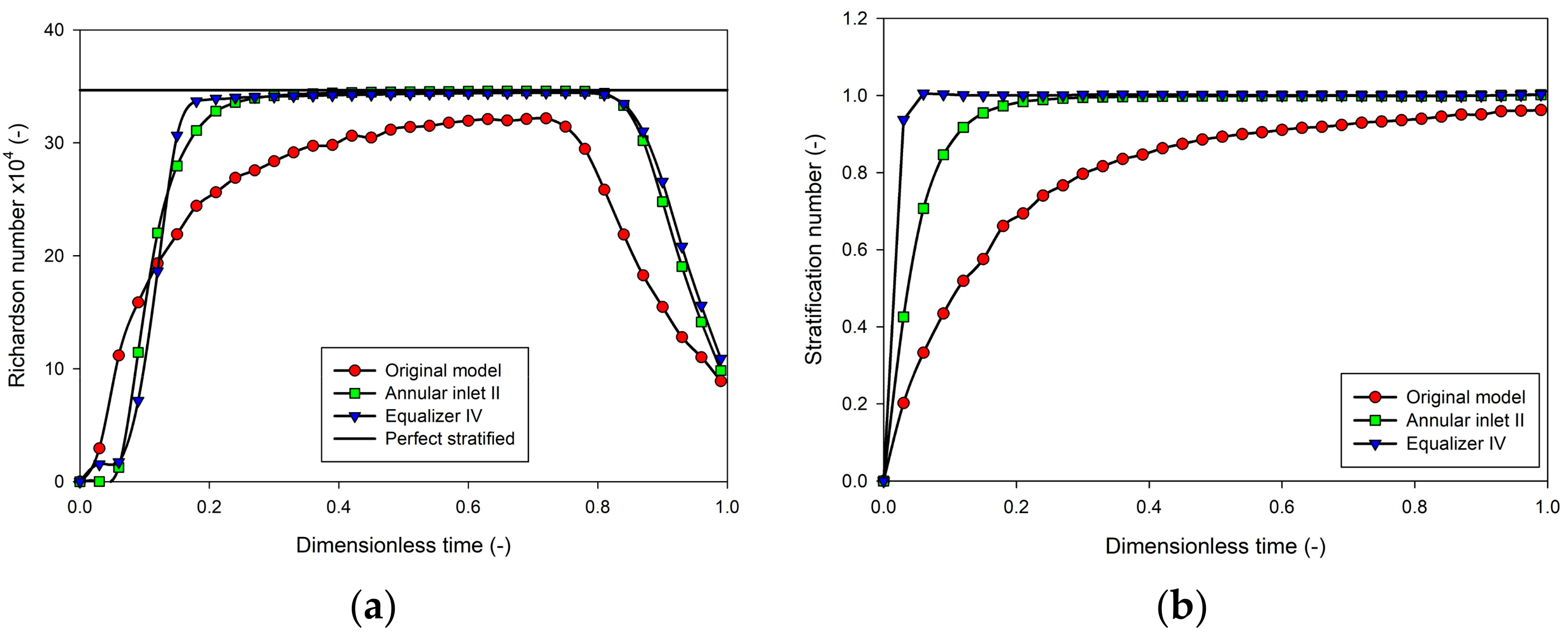
4.4. Comparison between the Annular Inlet II Model and the Equalizer IV Model
The two best temperature stratification models using modified inlet pipes, the annular inlet II model and the equalizer IV model, were compared via the Richardson number and the stratification number, as shown in
Figure 18. The results clearly showed that the Richardson number of both models could achieve the perfect stratified temperature. Nevertheless, the Richardson number of the equalizer IV model reached a faster and prolonged time of perfect stratification compared to the annular inlet II model. The stratification number of the equalizer IV model was equal to 1 at the dimensionless time of 0.075, while the annular inlet II model approached 1 at the dimensionless time of 0.2. This meant that the equalizer IV model developed a narrow thermocline faster and had a better temperature stratification. However, the discharging efficiencies between the equalizer IV model and the annular inlet II model were not significantly different, with only 1% more useful hot water in the equalizer model than in the annular inlet model.
4.5. Effect of Obstacle Plate Installation
The obstacle plate installation concept was proposed to regulate the water recirculation area limited within the under part of the storage tank. The factors of the plate length, the plate position, the number of plates, the characteristics of the curve-edged plate, and the perforated plates were focused on their effects on the degree of temperature stratification.
Figure 19 exhibits the Richardson number of various obstacle plate models. The results showed that the obstacle plate II model, which had one obstacle plate with a longer length located near the inlet pipe, gave the highest Richardson number value, similar to the obstacle plate VI model, which was a perforated plate with small hole diameters. The longer length of the obstacle plate II model effectively controlled the turbulent mixing area at the lower part of the storage tank, resulting in a faster and prolonged perfect stratification. Notably, increasing the number of obstacle plates had an inconsiderable impact on temperature stratification, as shown in the obstacle plate IV model, which had two plates configured within the tank. The installation of an obstacle plate with insufficient length, as in the obstacle plate V model, also had an insignificant impact on the improvement of temperature stratification.
The stratification number of the obstacle plate models, as presented in
Figure 20, had a similar tendency as the Richardson number. The obstacle plate II and obstacle plate VI models exhibited the highest stratification number. The stratification number of both models approached 1 after the dimensionless time was greater than 0.6, which meant a narrow thermocline was observed much later than in the best modified inlet pipe model. In previous work [
14], the obstacle plate I model has been presented and it could be seen that there was an improvement in thermal stratification. Therefore, further obstacle plate models were applied in this study. It was found that the installation of improper obstacle plate designs, such as obstacle plate I, III, and V models, could cause unclear temperature stratification and a turbulence zone throughout the entire discharge period, as illustrated in the temperature contours of
Figure 21. The thermocline layers’ heights in the obstacle plate II, IV, and VI models appeared slightly lower than the other models at the same dimensionless time. Considering the velocity profiles shown in
Figure 22, the turbulent mixing zones in the obstacle plate I, III, and V models had wider spread areas and higher velocity magnitudes, which resulted in inferior temperature stratification compared to the obstacle plate II, IV, and VI models.
The installation of proper obstacle plate design, such as in the obstacle plate II model, enhanced the degree of temperature stratification, which resulted in an increase of discharging efficiency to 81.5% (a 4% increase) as compared to the original tank model. On the other hand, the installation of an inappropriate obstacle plate design, such as in the obstacle plate III model, improved the discharging efficiency by only 1% compared to the unmodified tank, as shown in
Figure 23.
4.6. Comparison between the Modified Inlet Pipe and the Obstacle Plate Models
To define the factor influencing the thermal stratification within the thermal storage tank, the best modified inlet pipe model designs, such as the equalizer IV model that was designed to reduce the inlet water velocity, and the obstacle plate II model, which was constructed to restrain the water circulation zone, were compared. The Richardson number and the stratification number are comparably plotted in
Figure 24. The equalizer IV model clearly reached perfect stratification because the dimensionless time (0.2) was faster than the obstacle plate II model. Moreover, the stratification number and the temperature contour confirmed that the implementation of the equalizer IV model clearly produced a higher temperature stratification than the use of an obstacle plate, as represented via a narrow thermocline and quick temperature stratification, with the dimensionless time of 0.1. For the obstacle plate II model, the thermocline is distinct after the dimensionless time of 0.6. However, the thermocline layer was quite wide, and there was turbulent mixing of different water temperatures in the thermal storage tank, as seen in
Figure 25.
The discharging efficiencies of both models, as illustrated in
Figure 26, showed that the equalizer IV model had a higher discharging efficiency than the obstacle plate II model by approximately 5%. This meant an additional 25 L of useful hot water was obtained from the thermal storage tank installed with the equalizer IV, compared to the obstacle plate II model.
5. Conclusions
In this study, the storage tank was formulated to achieve a tank stratification to magnify the thermal efficiency of the heating device and to increase the amount of useful hot water delivered from the storage tank. The design concepts of reducing the inlet water velocity and limiting the water recirculation area were proposed to increase temperature stratification. A modified inlet pipe structure and an obstacle plate were implemented after using a numerical calculation for investigating the magnitude of temperature stratification in the thermal storage tank during the discharge period.
The accuracy of the simulation model and the setting conditions were validated with the experimental result via the parameter of water temperatures. The simulation result was reasonably satisfied with the experimental result, in which the deviation of water temperature was less than 3%.
For the modified inlet pipe, the parameters (i.e., the number, the size, and the direction of water outlets) and the installation of auxiliary equipment (i.e., the equalizer) were studied. The dimensionless terms, the temperature contour, and the velocity vector were employed to indicate the degree of thermal stratification. In the case of the modified inlet pipe without auxiliary equipment, due to the kinetic energy of incoming water by turning the inlet stream in a downward direction, the Annular II model, which contained six outlet holes with a hole diameter of 0.03 m, could provide better thermal stratification and induce faster separation between the hot and cold water than the perforated pipe, which had a smaller hole diameter and a greater number of holes. The Annular II model could enhance the discharging efficiency by about 3% higher than the perforated pipe model. However, it was found that the equalizer installation, which was implemented as auxiliary equipment, was the main parameter affecting temperature stratification, while the size, direction, and number of the water outlets were the inferior parameters. This was because the equalizer was designed under a combined concept that consisted of reducing the flow velocity by controlling the outlet direction flow toward the cover plate, changing the flow into the downward direction, and then slowing the outlet velocity with a perforated plate at the end of the pipe. This study showed that the equalizer IV model with a bigger diameter of 0.075 m could improve temperature stratification and provide the discharging efficiency of 86.1%, while the Annular II model could enhance the discharging efficiency to about 85%, compared to that of 77.3% for the original tank model.
For the installation of the obstacle plate, the longer obstacle plate length and the limited amount of water flowing through the perforated plate were the main parameters that decreased the turbulence of water mixing and, consequently, improved the storage tank’s temperature stratification. Mounting the obstacle plate closer to the inlet pipe was an inferior parameter. In this study, the obstacle plate II model, having a longer plate length of 517.5 mm mounted closer to the inlet pipe, could achieve the goal of limiting the recirculation area and providing better thermal stratification. Although the discharging efficiency of this obstacle plate model could increase to 81.5%, however, it was less than that of the equalizer IV model.
From this study, it can be concluded that the implementation of either a properly modified inlet pipe, such as in the equalizer model, or the appropriate obstacle plate design is desirable in the thermal storage tank because it can improve the thermal stratification, resulting in an increase in the energy efficiency of the thermal device and the availability of useful hot water. The modifier inlet pipe, by using the equalizer, provided a clearer advantage over the installation of the obstacle plate. The equalizer IV model, which was the best model, could increase the amount of useful hot water by 45 L, or approximately 9%, compared to the original model of the storage tank. To conclude, this work has provided a clear picture of the importance of thermal stratification in the energy storage tank and the efficient approach for enhancing the degree of thermal stratification.
Furthermore, the exergy analysis and the experimental validation of the modified inlet pipe models and the obstacle plate models will be considered in the next step.


