
Modulated Predictive Control to Improve the Steady-State Performance of NSI-Based Electrification Systems


Abstract
:1. Introduction
- A novel M2PC method is proposed to control two induction motors fed by a nine-switch inverter. The proposed strategy effectively controls the independent motors and provides a robust operation without undesired interactions.
- The steady-state performance is significantly improved by reducing the stator current THD and the torque ripple. The problem with the steady-state performance of the MPC strategy is solved by the proposed method without increasing the sampling frequency, and the stator current THD is reduced approximately by 50% at low current levels. The THD reduction in stator current also decreases the associated losses. The torque ripple is reduced by 25% under steady-state conditions.
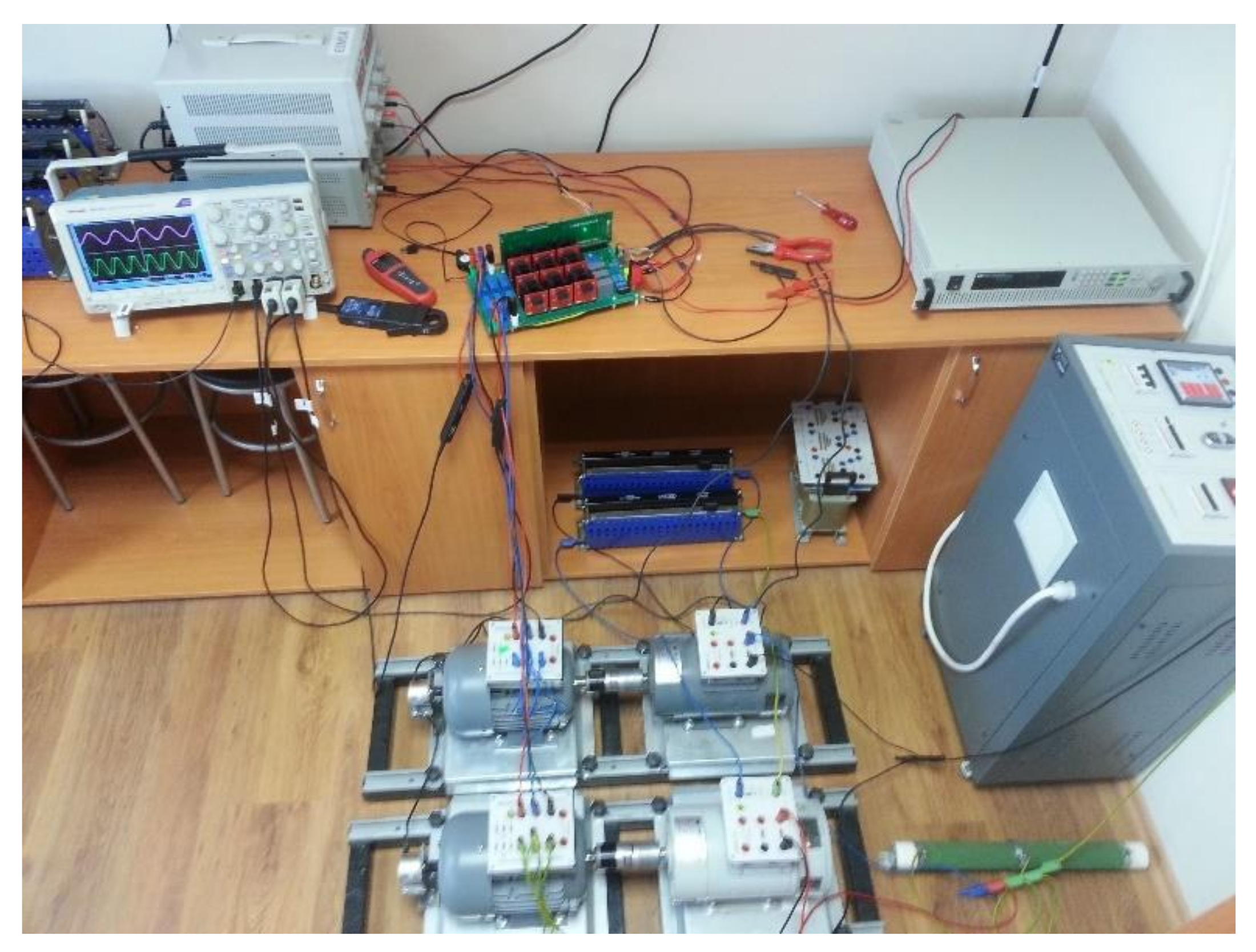
- The proposed method is then experimentally validated using a real hardware NSI prototype. The mathematical framework of the proposed method is proved under different real test scenarios. Different experimental cases are considered to demonstrate the effectiveness of the proposed method. Furthermore, comprehensive comparison works are performed between the proposed method and the traditional MPC strategy. Quantitative comparison results are provided to prove the advantages of the proposed method over the conventional MPC.
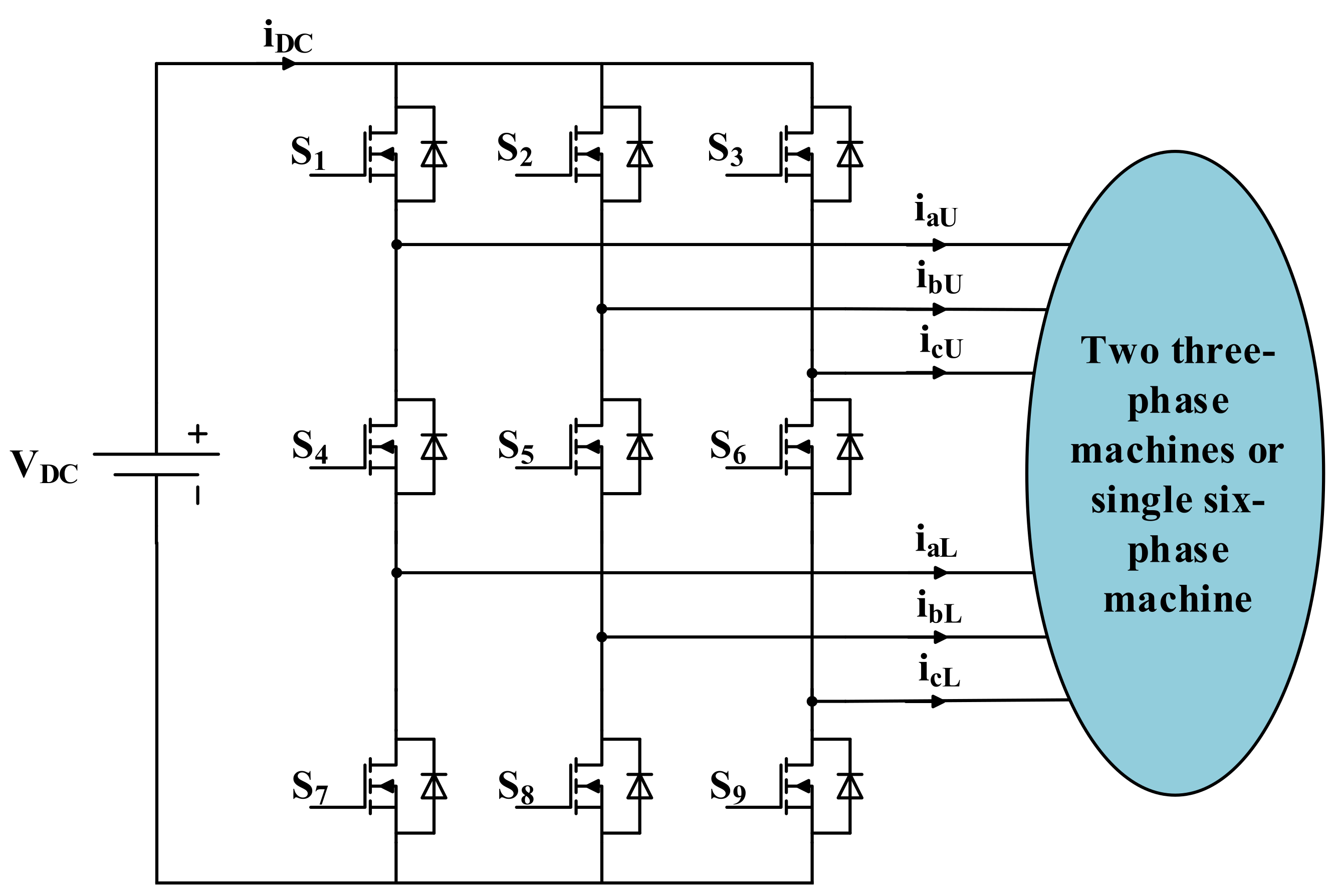
2. Nine-Switch Inverter Basics
3. Induction Machine Model
3.1. Dynamic Model of the Induction Machine
3.2. Discrete-Time Model of the Induction Machine
4. Control Strategy
4.1. Reference Generation in Indirect Field-Oriented Control of IM
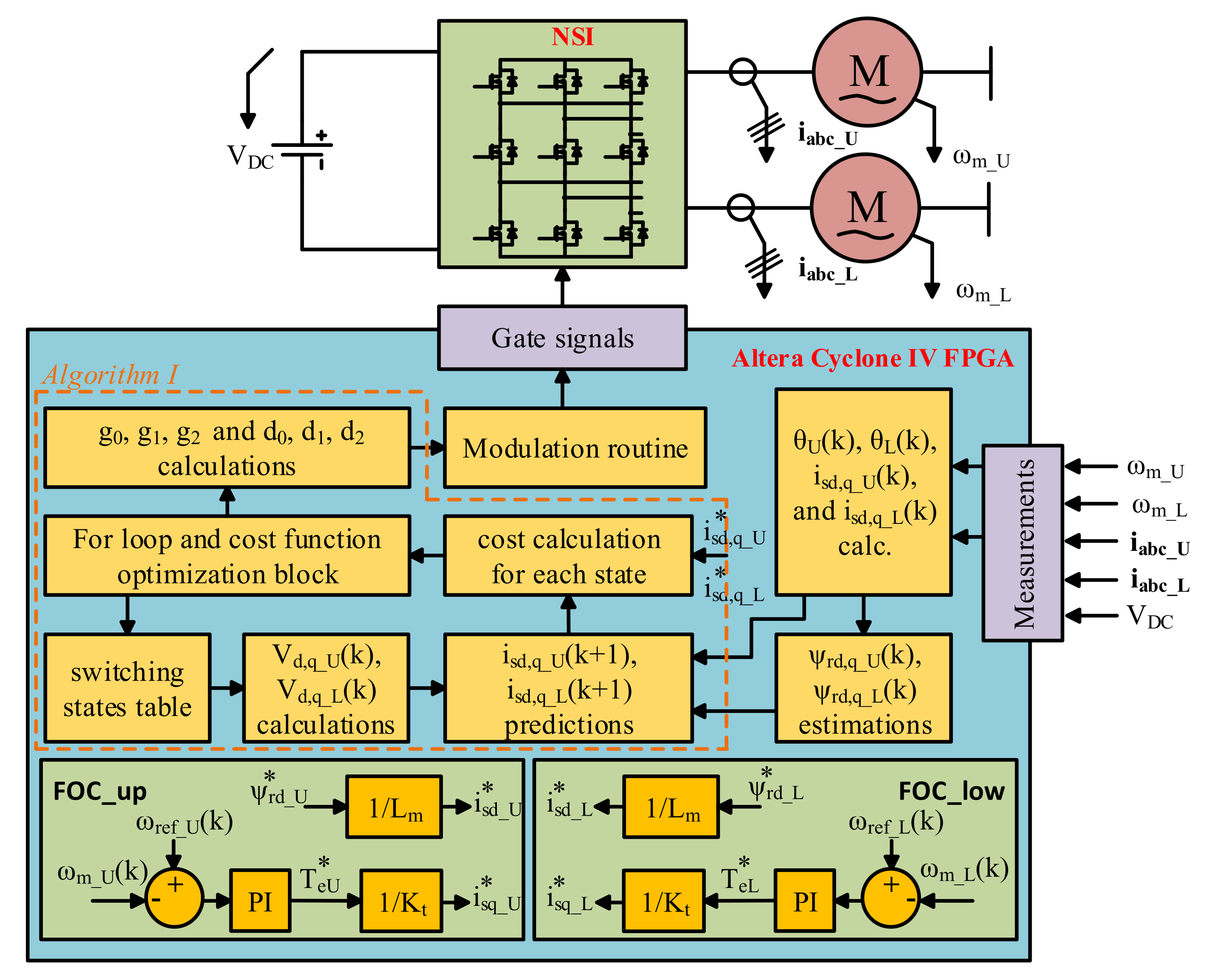
4.2. Proposed Modulated Model Predictive Control of NSI
| Algorithm 1 The routine for selecting the best two switching states and calculating the associated duty cycles |
| 1: for i = 3:27 |
| 2: calculate cost: Equation (27) |
| 3: if (i = = 3) then |
| 4: g0 = cost |
| 5: else |
| 6: if (cost < g1) then |
| 7: g2 = g1 |
| 8: g1 = cost |
| 9: index_of_g2 = index_of_g1 |
| 10: index_of_g1 = i |
| 11: elseif (cost < g2) then |
| 12: g2 = cost |
| 13: index_of_g2 = i |
| 14: end if |
| 15: end if |
| 16: end for |
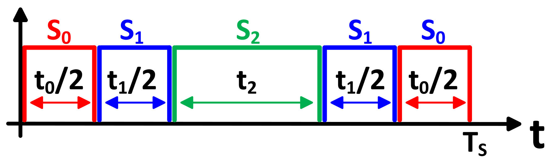
| 17: calculate duty cycles; d0, d1, d2: Equation (30) |
| 18: S0 = [1 1 1; 0 0 0; 1 1 1] |
| 19: S1 = sw (:, :, index_of_g1) |
| 20: S2 = sw (:, :, index_of_g2) |
| 21: if (sum(abs(S0−S1)) > sum(abs(S0−S2))) then |
| 22: temp_1 = S1 |
| 23: S1 = S2 |
| 24: S2 = temp_1 |
| 25: temp_2 = d1 |
| 26: d1 = d2 |
| 27: d2 = temp_2 |
| 28: end if |
5. Comparison with Other Control Strategies
6. Experimental Results
7. Conclusions
Funding
Acknowledgments
Conflicts of Interest
References
- Sathik, J.; Aleem, S.H.E.A.; Shalchi Alishah, R.; Almakhles, D.; Bertilsson, K.; Bhaskar, M.S.; Fernandez Savier, G.; Dhandapani, K. A Multilevel Inverter Topology Using Diode Half-Bridge Circuit with Reduced Power Component. Energies 2021, 14, 7249. [Google Scholar] [CrossRef]
- Kominami, T.; Fujimoto, Y. Inverter with Reduced Switching-Device Count for Independent AC Motor Control. In Proceedings of the IECON 2007—33rd Annual Conference of the IEEE Industrial Electronics Society, Taipei, Taiwan, 5–8 November 2007; pp. 1559–1564. [Google Scholar]
- Kominami, T.; Fujimoto, Y. A Novel Nine-Switch Inverter for Independent Control of Two Three-Phase Loads. In Proceedings of the 2007 IEEE Industry Applications Annual Meeting, New Orleans, LA, USA, 23–27 September 2007; pp. 2346–2350. [Google Scholar]
- Dabour, S.M.; Abdel-Khalik, A.S.; Ahmed, S.; Massoud, A.M. A Family of Discontinuous PWM Strategies for Quasi Z-Source Nine-Switch Inverters. IEEE Access 2021, 9, 169161–169176. [Google Scholar] [CrossRef]
- Pan, L.; Zhang, J.; Zhang, J.; Pang, Y.; Wang, B.; Wang, K.; Xu, D. A Novel Space-Vector Modulation Method for Nine-Switch Converter. IEEE Trans. Power Electron. 2020, 35, 1789–1804. [Google Scholar] [CrossRef]
- Li, X.; Qu, L.; Zhang, B.; Zhang, G.; Liao, H. A Simplified Modulation Strategy of Nine-Switch Inverter to Cut Off Half of Switching Modes. IEEE Access 2018, 6, 7254–7261. [Google Scholar] [CrossRef]
- Goyal, G.N.; Aware, M.V. Speed sensorless control of multiple induction motor drives with single nine switch inverter. In Proceedings of the 2017 International Conference on Energy, Communication, Data Analytics and Soft Computing (ICECDS), Chennai, India, 1–2 August 2017; pp. 3639–3644. [Google Scholar]
- Jarutus, N.; Kumsuwan, Y. A Carrier-Based Phase-Shift Space Vector Modulation Strategy for a Nine-Switch Inverter. IEEE Trans. Power Electron. 2017, 32, 3425–3441. [Google Scholar] [CrossRef]
- Dehghan, S.M.; Amiri, A.; Mohamadian, M.; Andersen, M.A.E. Modular space-vector pulse-width modulation for nine-switch converters. IET Power Electron. 2013, 6, 457–467. [Google Scholar] [CrossRef] [Green Version]
- Gao, F.; Zhang, L.; Li, D.; Loh, P.C.; Tang, Y.; Gao, H. Optimal Pulsewidth Modulation of Nine-Switch Converter. IEEE Trans. Power Electron. 2010, 25, 2331–2343. [Google Scholar] [CrossRef]
- Dehnavi, S.M.D.; Mohamadian, M.; Yazdian, A.; Ashrafzadeh, F. Space Vectors Modulation for Nine-Switch Converters. IEEE Trans. Power Electron. 2010, 25, 1488–1496. [Google Scholar] [CrossRef]
- Ali, K.; Das, P.; Panda, S.K. A Special Application Criterion of the Nine-Switch Converter with Reduced Conduction Loss. IEEE Trans. Ind. Electron. 2018, 65, 2853–2862. [Google Scholar] [CrossRef]
- de Andrade, F.C.; Bradaschia, F.; Limongi, L.R.; Cavalcanti, M.C. A Reduced Switching Loss Technique Based on Generalized Scalar PWM for Nine-Switch Inverters. IEEE Trans. Ind. Electron. 2018, 65, 38–48. [Google Scholar] [CrossRef]
- Qin, Z.; Loh, P.C.; Blaabjerg, F. Application Criteria for Nine-Switch Power Conversion Systems with Improved Thermal Performance. IEEE Trans. Power Electron. 2015, 30, 4608–4620. [Google Scholar] [CrossRef]
- Qin, Z.; Loh, P.C.; Bahman, A.S.; Blaabjerg, F. Evaluation of current stresses in nine-switch energy conversion systems. IET Power Electron. 2014, 7, 2877–2886. [Google Scholar] [CrossRef]
- Dehghan, S.M.; Mohamadian, M.; Yazdian, A. Hybrid Electric Vehicle Based on Bidirectional Z-Source Nine-Switch Inverter. IEEE Trans. Veh. Technol. 2010, 59, 2641–2653. [Google Scholar] [CrossRef]
- Pinjala, M.K.; Bhimasingu, R. Improving the DC-Link Utilization of Nine-Switch Boost Inverter Suitable for Six-Phase Induction Motor. IEEE Trans. Transp. Electrif. 2020, 6, 1177–1187. [Google Scholar] [CrossRef]
- Diab, M.S.; Elserougi, A.A.; Abdel-Khalik, A.S.; Massoud, A.M.; Ahmed, S. A Nine-Switch-Converter-Based Integrated Motor Drive and Battery Charger System for EVs Using Symmetrical Six-Phase Machines. IEEE Trans. Ind. Electron. 2016, 63, 5326–5335. [Google Scholar] [CrossRef]
- Wen, G.; Chen, Y.; Zhong, Z.; Kang, Y. Dynamic Voltage and Current Assignment Strategies of Nine-Switch-Converter-Based DFIG Wind Power System for Low-Voltage Ride-Through (LVRT) Under Symmetrical Grid Voltage Dip. IEEE Trans. Ind. Appl. 2016, 52, 3422–3434. [Google Scholar] [CrossRef]
- Liu, X.; Loh, P.C.; Wang, P.; Blaabjerg, F. A Direct Power Conversion Topology for Grid Integration of Hybrid AC/DC Energy Resources. IEEE Trans. Ind. Electron. 2013, 60, 5696–5707. [Google Scholar] [CrossRef]
- Gulbudak, O.; Gokdag, M. Dual-Hysteresis Band Control of Nine-Switch Inverter to Control Two Induction Motors. IEEE Trans. Energy Convers. 2021, 1. [Google Scholar] [CrossRef]
- Abbache, M.A.; Tabbache, B.; Douida, S.; Benbouzid, M. Direct torque control scheme for nine switches inverter fed two induction motors-based more electric vehicle powertrains. Int. Trans. Electr. Energy Syst. 2021, 31, e13175. [Google Scholar] [CrossRef]
- Wei, J.; Zhang, T.; Shi, L.; Zhou, B. Dual-Stator Doubly Salient Electromagnetic Motor Driving System Utilizing a Nine-Switch Converter. IEEE Trans. Ind. Appl. 2019, 55, 1550–1560. [Google Scholar] [CrossRef]
- Reusser, C.A. Full-electric ship propulsion, based on a dual nine-switch inverter topology for dual three-phase induction motor drive. In Proceedings of the 2016 IEEE Transportation Electrification Conference and Expo (ITEC), Busan, Korea, 1–4 June 2016; pp. 1–6. [Google Scholar]
- dos Santos, E.C.; Jacobina, C.B.; da Silva, O.I. Six-phase machine drive system with nine-switch converter. In Proceedings of the IECON 2011—37th Annual Conference of the IEEE Industrial Electronics Society, Melbourne, Australia, 7–10 November 2011; pp. 4204–4209. [Google Scholar]
- Oka, K.; Matsuse, K. A nine-switch inverter for driving two AC motors independently. IEEJ Trans. Electr. Electron. Eng. 2007, 2, 94–96. [Google Scholar] [CrossRef]
- Gulbudak, O.; Gokdag, M. Finite control set model predictive control approach of nine switch inverter-based drive systems: Design, analysis, and validation. ISA Trans. 2021, 110, 283–304. [Google Scholar] [CrossRef]
- Barrero, F.; Arahal, M.R.; Gregor, R.; Toral, S.; Durán, M.J. A proof of concept study of predictive current control for VSI-driven asymmetrical dual three-phase AC machines. IEEE Trans. Ind. Electron. 2009, 56, 1937–1954. [Google Scholar] [CrossRef]
- Wang, F.; Mei, X.; Rodriguez, J.; Kennel, R. Model predictive control for electrical drive systems-an overview. CES Trans. Electr. Mach. Syst. 2020, 1, 219–230. [Google Scholar] [CrossRef]
- Elmorshedy, M.F.; Xu, W.; El-Sousy, F.F.M.; Islam, M.R.; Ahmed, A.A. Recent Achievements in Model Predictive Control Techniques for Industrial Motor: A Comprehensive State-of-the-Art. IEEE Access 2021, 9, 58170–58191. [Google Scholar] [CrossRef]
- Gokdag, M.; Gulbudak, O. Dual-model predictive control of two independent induction motors driven by a SiC nine-switch inverter. Int. J. Electron. 2021, 1–19. [Google Scholar] [CrossRef]
- Zhang, Y.; Xia, B.; Yang, H.; Rodriguez, J. Overview of model predictive control for induction motor drives. Chin. J. Electr. Eng. 2019, 2, 62–76. [Google Scholar] [CrossRef]
- Reyes Dreke, V.D.; Lazar, M. Long-Horizon Nonlinear Model Predictive Control of Modular Multilevel Converters. Energies 2022, 15, 1376. [Google Scholar] [CrossRef]
- Chen, G.-J.; Liu, Y.-H.; Cheng, Y.-S.; Pai, H.-Y. A Novel Optimal Charging Algorithm for Lithium-Ion Batteries Based on Model Predictive Control. Energies 2021, 14, 2238. [Google Scholar] [CrossRef]
- Vazquez, S.; Acuna, P.; Aguilera, R.P.; Pou, J.; Leon, J.I.; Franquelo, L.G. DC-Link Voltage-Balancing Strategy Based on Optimal Switching Sequence Model Predictive Control for Single-Phase H-NPC Converters. IEEE Trans. Ind. Electron. 2020, 67, 7410–7420. [Google Scholar] [CrossRef]
- Zhang, K.; Fan, M.; Yang, Y.; Chen, R.; Zhu, Z.; Garcia, C.; Rodriguez, J. Tolerant Sequential Model Predictive Direct Torque Control of Permanent Magnet Synchronous Machine Drives. IEEE Trans. Transp. Electrif. 2020, 6, 1167–1176. [Google Scholar] [CrossRef]
- Sankar, D.; Syamala, L.; Chembathu Ayyappan, B.; Kallarackal, M. FPGA-Based Cost-Effective and Resource Optimized Solution of Predictive Direct Current Control for Power Converters. Energies 2021, 14, 7669. [Google Scholar] [CrossRef]
- Zheng, C.; Dragicevic, T.; Majmunovic, B.; Blaabjerg, F. Constrained Modulated Model-Predictive Control of an LC -Filtered Voltage-Source Converter. IEEE Trans. Power Electron. 2020, 35, 1967–1977. [Google Scholar] [CrossRef]
- Zucuni, J.P.; Carnielutti, F.; Pinheiro, H.; Norambuena, M.; Rodriguez, J. Cost Function Design for Stability Assessment of Modulated Model Predictive Control. In Proceedings of the 2020 22nd European Conference on Power Electronics and Applications (EPE’20 ECCE Europe), Virtual, 7–11 September 2020; pp. P.1–P.9. [Google Scholar]
- Aguirre, M.; Kouro, S.; Rojas, C.A.; Vazquez, S. Enhanced Switching Frequency Control in FCS-MPC for Power Converters. IEEE Trans. Ind. Electron. 2021, 68, 2470–2479. [Google Scholar] [CrossRef]
- Yang, Y.; Wen, H.; Fan, M.; Xie, M.; Peng, S.; Norambuena, M.; Rodriguez, J. Computation-Efficient Model Predictive Control With Common-Mode Voltage Elimination for Five-Level ANPC Converters. IEEE Trans. Transp. Electrif. 2020, 6, 970–984. [Google Scholar] [CrossRef]
- Mora, A.; Cardenas-Dobson, R.; Aguilera, R.P.; Angulo, A.; Donoso, F.; Rodriguez, J. Computationally Efficient Cascaded Optimal Switching Sequence MPC for Grid-Connected Three-Level NPC Converters. IEEE Trans. Power Electron. 2019, 34, 12464–12475. [Google Scholar] [CrossRef]
- Song, W.; Xue, C.; Wu, X.; Yu, B. Modulated Finite-Control-Set Model Predictive Current Control for Five-Phase Voltage-Source Inverter. IEEE Trans. Transp. Electrif. 2021, 7, 718–729. [Google Scholar] [CrossRef]
- Yaramasu, V.; Milev, K.; Dekka, A.; Rivera, M.; Rodriguez, J.; Rojas, F. Modulated Model Predictive Current Control of a Four-Leg Inverter. In Proceedings of the 2020 11th Power Electronics, Drive Systems, and Technologies Conference, Tehran, Iran, 4–6 February 2020. [Google Scholar]
- Garcia, C.; Rodriguez, J.; Odhano, S.; Zanchetta, P.; Davari, S.A. Modulated Model Predictive Speed Control for PMSM Drives. In Proceedings of the 2018 IEEE International Conference on Electrical Systems for Aircraft, Railway, Ship Propulsion and Road Vehicles & International Transportation Electrification Conference, Nottingham, UK, 7–9 November 2018. [Google Scholar] [CrossRef]
- Wang, Q.; Yu, H.; Li, C.; Lang, X.; Yeoh, S.S.; Yang, T.; Rivera, M.; Bozhko, S.; Wheeler, P. A Low-Complexity Optimal Switching Time-Modulated Model-Predictive Control for PMSM with Three-Level NPC Converter. IEEE Trans. Transp. Electrif. 2020, 6, 1188–1198. [Google Scholar] [CrossRef]
- Liu, Y.; Cheng, S.; Zhao, Y.; Liu, J.; Li, Y. Optimal two-vector combination-based model predictive current control with compensation for PMSM drives. Int. J. Electron. 2019, 106, 880–894. [Google Scholar] [CrossRef]
- Ayala, M.; Doval-Gandoy, J.; Rodas, J.; Gonzalez, O.; Gregor, R.; Rivera, M. A Novel Modulated Model Predictive Control Applied to Six-Phase Induction Motor Drives. IEEE Trans. Ind. Electron. 2021, 68, 3672–3682. [Google Scholar] [CrossRef]
- Gregor, R.; Barrero, F.; Toral, S.L.; Durán, M.J.; Arahal, M.R.; Prieto, J.; Mora, J.L. Predictive-space vector PWM current control method for asymmetrical dual three-phase induction motor drives. IET Electr. Power Appl. 2010, 4, 26. [Google Scholar] [CrossRef] [Green Version]
- Jabłoński, M.; Borkowski, P. Correction Mechanism for Balancing Driving Torques in an Opencast Mining Stacker with an Induction Motor and Converter Drive System. Energies 2022, 15, 1282. [Google Scholar] [CrossRef]
- González, E.; Sanchis, J.; García-Nieto, S.; Salcedo, J. A Comparative Study of Stochastic Model Predictive Controllers. Electronics 2020, 9, 2078. [Google Scholar] [CrossRef]
- Calderón, A.J.; Vivas, F.J.; Segura, F.; Andújar, J.M. Integration of a Multi-Stack Fuel Cell System in Microgrids: A Solution Based on Model Predictive Control. Energies 2020, 13, 4924. [Google Scholar] [CrossRef]
- Sevinç, A. Speed Sensorless Control of Induction Motors; University of Bristol: Bristol, UK, 2001. [Google Scholar]


| Group | States | NSI Switch Position * | VaUn | VbUn | VcUn | VaLn’ | VbLn’ | VcLn’ |
|---|---|---|---|---|---|---|---|---|
| I | sw1 | [1 1 1; 1 1 1; 0 0 0] | 0 | 0 | 0 | 0 | 0 | 0 |
| sw2 | [0 0 0; 1 1 1; 1 1 1] | 0 | 0 | 0 | 0 | 0 | 0 | |
| sw3 | [1 1 1; 0 0 0; 1 1 1] | 0 | 0 | 0 | 0 | 0 | 0 | |
| II | sw4 | [1 0 0; 0 1 1; 1 1 1] | (2/3) VDC | (−1/3) VDC | (−1/3) VDC | 0 | 0 | 0 |
| sw5 | [1 1 0; 0 0 1; 1 1 1] | (1/3) VDC | (1/3) VDC | (−2/3) VDC | 0 | 0 | 0 | |
| sw6 | [0 1 0; 1 0 1; 1 1 1] | (−1/3) VDC | (2/3) VDC | (−1/3) VDC | 0 | 0 | 0 | |
| sw7 | [0 1 1; 1 0 0; 1 1 1] | (−2/3) VDC | (1/3) VDC | (1/3)VDC | 0 | 0 | 0 | |
| sw8 | [0 0 1; 1 1 0; 1 1 1] | (−1/3) VDC | (−1/3) VDC | (2/3) VDC | 0 | 0 | 0 | |
| sw9 | [1 0 1; 0 1 0; 1 1 1] | (1/3) VDC | (−2/3) VDC | (1/3) VDC | 0 | 0 | 0 | |
| sw10 | [1 1 1; 1 0 0; 0 1 1] | 0 | 0 | 0 | (2/3) VDC | (−1/3) VDC | (−1/3) VDC | |
| sw11 | [1 1 1; 1 1 0; 0 0 1] | 0 | 0 | 0 | (1/3) VDC | (1/3) VDC | (−2/3) VDC | |
| sw12 | [1 1 1; 0 1 0; 1 0 1] | 0 | 0 | 0 | (−1/3) VDC | (2/3) VDC | (−1/3) VDC | |
| sw13 | [1 1 1; 0 1 1; 1 0 0] | 0 | 0 | 0 | (−2/3) VDC | (1/3) VDC | (1/3) VDC | |
| sw14 | [1 1 1; 0 0 1; 1 1 0] | 0 | 0 | 0 | (−1/3) VDC | (−1/3) VDC | (2/3) VDC | |
| sw15 | [1 1 1; 1 0 1; 0 1 0] | 0 | 0 | 0 | (1/3) VDC | (−2/3) VDC | (1/3) VDC | |
| III | sw16 | [1 0 0; 1 1 1; 0 1 1] | (2/3) VDC | (−1/3) VDC | (−1/3) VDC | (2/3) VDC | (−1/3) VDC | (−1/3) VDC |
| sw17 | [1 1 0; 1 1 1; 0 0 1] | (1/3) VDC | (1/3) VDC | (−2/3) VDC | (1/3) VDC | (1/3) VDC | (−2/3) VDC | |
| sw18 | [0 1 0; 1 1 1; 1 0 1] | (−1/3) VDC | (2/3) VDC | (−1/3) VDC | (−1/3) VDC | (2/3) VDC | (−1/3) VDC | |
| sw19 | [0 1 1; 1 1 1; 1 0 0] | (−2/3) VDC | (1/3) VDC | (1/3) VDC | (−2/3) VDC | (1/3) VDC | (1/3) VDC | |
| sw20 | [0 0 1; 1 1 1; 1 1 0] | (−1/3) VDC | (−1/3) VDC | (2/3) VDC | (−1/3) VDC | (−1/3) VDC | (2/3) VDC | |
| sw21 | [1 0 1; 1 1 1; 0 1 0] | (1/3) VDC | (−2/3) VDC | (1/3) VDC | (1/3) VDC | (−2/3) VDC | (1/3) VDC | |
| sw22 | [1 1 0; 1 0 1; 0 1 1] | (1/3) VDC | (1/3) VDC | (−2/3) VDC | (2/3) VDC | (−1/3) VDC | (−1/3) VDC | |
| sw23 | [1 1 0; 0 1 1; 1 0 1] | (1/3) VDC | (1/3) VDC | (−2/3) VDC | (−1/3) VDC | (2/3) VDC | (−1/3) VDC | |
| sw24 | [0 1 1; 1 1 0; 1 0 1] | (−2/3) VDC | (1/3) VDC | (1/3) VDC | (−1/3) VDC | (2/3) VDC | (−1/3) VDC | |
| sw25 | [0 1 1; 1 0 1; 1 1 0] | (−2/3) VDC | (1/3) VDC | (1/3) VDC | (−1/3) VDC | (−1/3) VDC | (2/3) VDC | |
| sw26 | [1 0 1; 0 1 1; 1 1 0] | (1/3) VDC | (−2/3) VDC | (1/3) VDC | (−1/3) VDC | (−1/3) VDC | (2/3) VDC | |
| sw27 | [1 0 1; 1 1 0; 0 1 1] | (1/3) VDC | (−2/3) VDC | (1/3) VDC | (2/3) VDC | (−1/3) VDC | (−1/3) VDC |
| Description | Parameter | Value |
|---|---|---|
| stator inductance | Ls | 452.3 mH |
| rotor inductance | Lr | 452.3 mH |
| mutual inductance | Lm | 442.2 mH |
| pole pair | p | 2 |
| stator resistance | Rs | 3.9190 Ω |
| rotor resistance | Rr | 4.9618 Ω |
| friction factor | B | 0.002985 N·m·s |
| inertia | J | 0.0131 kg·m2 |
| stator flux reference | Ψ*s | 0.61 Wb. |
| dc-link voltage | VDC | 250 V |
| sampling period of the inner loop | Ts | 100 µs |
| PI parameter | Kp | 1 |
| PI parameter | Ki | 16 |
| PI controller discretization period | Ts_PI | 5 ms |
| Compared Quantity → Control Strategy↓ | Scenario I | Scenario II | Execution Time | ||
|---|---|---|---|---|---|
| THD% for Upper Load | THD% for Lower Load | THD% for Upper Load | THD% for Lower Load | ||
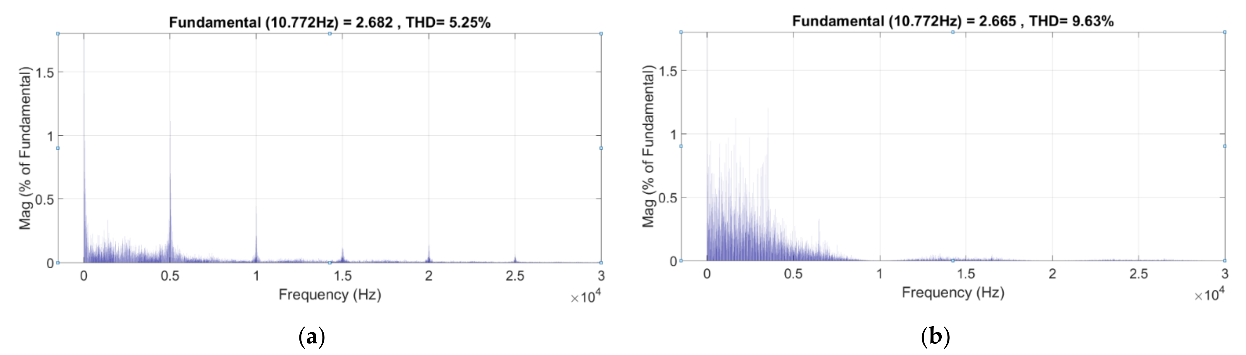
| Proposed Method | 6.79 | 6.79 | 5.99 | 5.25 | 202.4 μs |
| FCS-MPC | 18.44 | 19.64 | 11.66 | 9.63 | 165.7 μs |
| PTC | 18.98 | 20.10 | 11.39 | 9.79 | 170.1 μs |
| Hysteresis | 22.76 | 23.15 | 14.48 | 12.70 | 67.66 μs |
| Compared Quantity→ Control Strategy↓ | Scenario I | Scenario II | Sampling Period | Execution Time | CBR | ||
|---|---|---|---|---|---|---|---|
| THD% for Upper Load | THD% for Lower Load | THD% for Upper Load | THD% for Lower Load | ||||
| Proposed Method | 6.79 | 6.79 | 5.99 | 5.25 | 100 μs | 202.4 μs | 2.2024 |
| FCS-MPC | 7.50 | 8.03 | 4.59 | 4.37 | 40 μs | 165.7 μs | 4.1430 |
Publisher’s Note: MDPI stays neutral with regard to jurisdictional claims in published maps and institutional affiliations. |
© 2022 by the author. Licensee MDPI, Basel, Switzerland. This article is an open access article distributed under the terms and conditions of the Creative Commons Attribution (CC BY) license (https://creativecommons.org/licenses/by/4.0/).
Share and Cite
Gokdag, M. Modulated Predictive Control to Improve the Steady-State Performance of NSI-Based Electrification Systems. Energies 2022, 15, 2043. https://doi.org/10.3390/en15062043
Gokdag M. Modulated Predictive Control to Improve the Steady-State Performance of NSI-Based Electrification Systems. Energies. 2022; 15(6):2043. https://doi.org/10.3390/en15062043
Chicago/Turabian StyleGokdag, Mustafa. 2022. "Modulated Predictive Control to Improve the Steady-State Performance of NSI-Based Electrification Systems" Energies 15, no. 6: 2043. https://doi.org/10.3390/en15062043