1. Introduction
A printed circuit heat exchanger (PCHE) is a type of compact heat exchanger with high efficiency, high application pressure, and high application temperature. It was invented in Australia in 1980 and promoted for commercial application by Heatric. It has broad application prospects in the fields of ultra-high-temperature gas-cooled reactors, floating liquefied natural gas storage units, and other industrial energy [
1]. PCHE typically employs diffusion-bonded arrays of plates where microchannels are formed by chemical etching [
2]. The typical cross section shape is semicircular and the hydraulic diameter in a PCHE passage is between 700 μm and 1.5 mm [
3]. The flow channel geometries can be designed as straight, zigzag, S-shape, and airfoil-finned channels [
4]. However, the zigzag-type channel is more widely used in industrial applications. CO
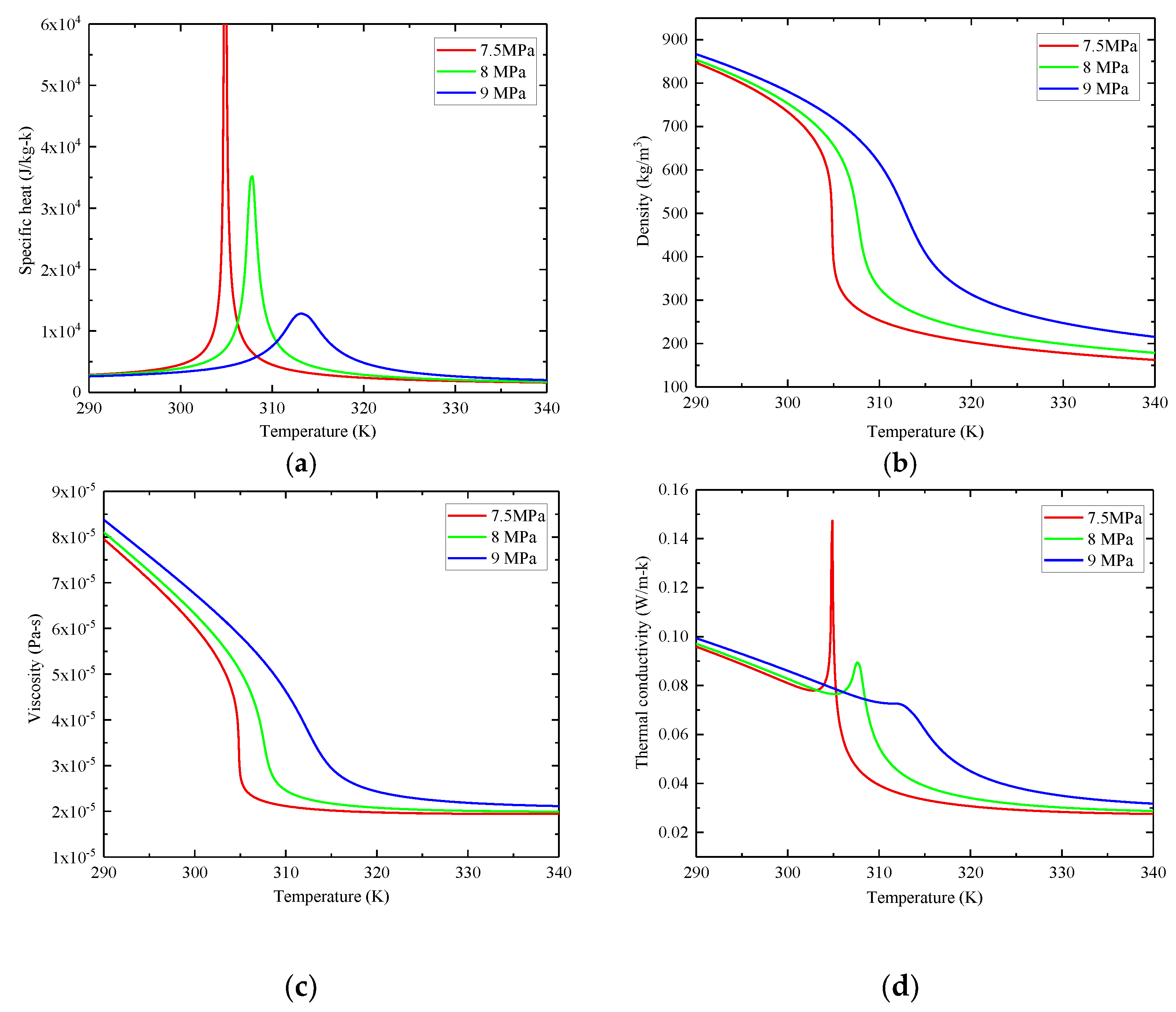
2 is a nontoxic and inexpensive gas. It has excellent thermophysical properties (high specific heat, high thermal conductivity, and low viscosity) near the pseudocritical point, as shown in
Figure 1, which can considerably enhance the heat transfer without sacrificing the hydraulic performance [
5]. Consequently, the application of CO
2 in PCHE has become the focus of researchers.
Heat transfer and hydraulic characteristics are the basis of PCHE thermal design. Various experimental and numerical investigations have been performed to optimize the channel structures, fluid mediums, and operation conditions. Nikitin and his team first published the experimental results of the flow and heat transfer characteristics of sCO
2 in zigzag PCHE in 2016 and developed the correlations of
Nu and
f, while the correlations are only applicable to channels of the specific geometric parameters and Reynolds number range of those used in the experimental study [
6]. Kruizenga et al. investigated the thermal–hydraulic performance of sCO
2 in a straight channel with semicircular cross section using both experimental and numerical methods, the analysis results showed that the commercial computational fluid dynamics (CFD) software can well predict the internal heat transfer characteristics of the PCHE channel [
7]. Saeed and Kim also conducted the numerical analysis of an sCO
2 PCHE using ANSYS-CFX and validated the simulation results using published experimental data [
8]. Tu and Zeng studied the flow and heat transfer performance in semicircular straight channels of sCO
2 fluid for both cooling and heating process using CFD method. A modified model based on Douglas A. Olson [
9] correlation was proposed to predict the heat transfer performance of sCO
2 in semicircular channels for both heating and cooling conditions [
10]. These literature conclusions fully confirm the feasibility of the numerical method.
Subsequently, a large number of studies focused on finding better channel types. Kim et al. compared the heat transfer and hydraulic performance of sCO
2 in PCHE with zigzag and airfoil-shaped fins. It was found that the thermal performance of the airfoil fin was close to that of zigzag, but the airfoil fin had lower pressure loss [
11]. Mohammed et al. investigated the effect of channel shapes (zigzag, curve, and step) on the thermal and hydraulic performance of PCHE and found that the zigzag channels have the highest value of heat transfer coefficient and pressure drop [
12]. Matsuo et al. conducted numerical simulations of three different channel types (zigzag, chamfered zigzag, airfoil) to study the geometrical effects on the local heat transfer coefficient and pressure drop for supercritical CO
2 in PCHE and developed new correlations for
Nu of the zigzag channels [
13]. In the research of [
14,
15,
16], the PCHE with zigzag channel and discontinuous S-shaped fins were numerically and experimentally investigated, and it was found that the S-shaped channel can significantly improve the hydraulic performance while keeping almost equal heat transfer performance compared to the zigzag channels.
There are also studies focusing on thermal hydraulic characteristics of the other fluid media in PCHE channels. Dai et al. studied the flow and heat transfer performance of water in the semicircular zigzag passage experimentally [
17]. Minghui Chen et al. investigated the thermal–hydraulic performance of a zigzag channel PCHE using helium as fluid media [
18].
Most of the studies on the flow and heat transfer characteristics of PCHE channels use a specific geometric parameter channel or straight channel, or the comparison between zigzag channel and other types of channels such as S-type and discontinuous airfoil fin type. The experimental data and empirical correlations given in these studies are also limited to a certain type of channel, and the operating pressure, fluid bulk temperature, and Reynolds number are limited to a certain range. However, there are few studies on the effect of geometric parameters on the flow and heat transfer performance of a zigzag channel. This paper aims at modeling the forced convection heat transfer of CO2 within the zigzag channels, which are the main channel type of PCHE, and studies the effects of its main geometric parameters (hydraulic diameter, pitch length, and bending angle) on its internal flow and heat transfer parameters, especially near the pseudocritical point. The numerical method and analysis results of this study can be used as a reference for PCHE industrial design and channel performance investigation.
2. Numerical Modeling
A numerical method for analyzing the steady-state flow and heat transfer properties of a zigzag channel is defined. In this method, ANSYS Fluent 2019 is used to solve the governing equations of the steady turbulent flow of sCO
2 in the zigzag channels. The NIST real gas model with REFPROP V9.1 database was used to evaluate the thermodynamics and transport of approximately of CO
2. Yoon et al. [
19] and Ren et al. [
20] conducted comparative studies using STD k–e, realizable k–e, and SST (shear stress transport) k–ω turbulence models to simulate the thermal–hydraulic performance of sCO
2 intube-flowing and found that the SST k–ω turbulence model gives the best quantitative prediction. The same conclusion was likewise reached in [
21,
22,
23,
24]. Therefore, the SST k–ω model is adopted for further analysis in this study. The pressure-based coupled algorithm was used to establish the coupling of velocity and pressure. The numerical simulation is considered convergent as all iterative residuals of the governing equations are less than 10
−5, and area-weighted average outlet temperature and area-weighted average inlet pressure are stable.
2.1. Geometry and Boundary Conditions
The flow and heat transfer performance of CO
2 in horizontal zigzag channels is investigated in this paper.
Figure 2 shows a schematic diagram of the computational domain with the boundary condition adopted in this research. The study will consider the effects of different geometric factors, including hydraulic diameter, bending angle, and pitch length on the internal flow and heat transfer characteristics of the channel, as shown in
Table 1. To check the independent effect of the geometric parameter, the comparative study only changes one geometric parameter at a time, and the rest remains unchanged. For example, for investigating the effect of bend angle
θ on the channel flow and heat transfer performance, four types of bend angle, 100°, 115°, 140°, and 180° (straight), are considered for the geometric model, while
Lp is fixed to 7.75 mm and
dh is fixed to 2 mm.
As shown in
Table 2, the inlet temperature was changed from 280 K to 350 K to ensure the bulk temperature
Tb covers the pseudocritical point of CO
2 for this analysis. The outlet pressure of CO
2 varies between 7.5 MPa and 9 MPa to keep its condition near the pseudocritical point. Constant wall heat flux (12 kW/m
2 for heating case and −12 kW/m
2 for cooling case) and mass flux 200 kg/m
2-s were adopted in this numerical simulation. The thermal properties of CO
2 were obtained from NIST Database (REFPROP V9.1).
2.2. Governing Equations
The governing equations regarding the continuity, momentum, and energy are expressed as Equations (1)–(3).
(2) Momentum equation [
25]:
(3) Energy equation:
where
is the gravitational body force,
is overall velocity vector,
T is the temperature,
is the density,
is the velocity vector,
E is the total energy,
p is the static pressure,
is the stress tensor, and
is the effective conductivity (
,
is the turbulent thermal conductivity).
(4) Direct numerical simulation (DNS) of Navier–Stokes equations is the most accurate method for turbulence; however, it is not feasible in most situations to resolve the wide range of scales in time and space as the CPU requirements by far exceed the existing capacity. For this reason, averaging procedures such as the Reynolds method have to be applied to the Navier–Stokes equations to filter out the turbulent spectrum [
26]. However, the averaging process introduces additional unknown terms into the transport equations that need to be provided by suitable turbulence models. The SST
k–
ω turbulence model is used in this paper and is described as follows.
The transport equations of the
k–
ω model are expressed as Equations (4) and (5):
where
is the generation of turbulence kinetic energy
k due to mean velocity gradients,
is the generation of
, and
and
represent the effective diffusivity of
k and
calculated by Equations (6) and (7).
where
and
are turbulent Prandtl numbers for
k and
, respectively,
is the dynamic viscosity of the fluid, and
is calculated as Equations (8)–(10).
The turbulent viscosity
of the SST
model is calculated using Equations (11)–(15).
where
is the turbulent viscosity,
y is the wall distance, and the constants used in the SST model are as follows:
= 0.31,
,
,
,
.
The second-order upwind scheme of Equation (16) is used to discretize the convective term of the above governing Equation [
27].
where
and
are the cell-centered value and its gradient in the upstream cell and
is the displacement vector from upstream cell centroid to the face centroid.
2.3. Data Reduction
The hydraulic diameter,
dh, was defined as Equation (17):
where
A is the semicircular cross section area of the channel, and
is the wet circumference of the cross section.
The average heat convection coefficient,
h, was defined as Equation (18):
where
is the heat flux of the wall,
is the average wall temperature, and
is the fluid bulk temperature.
The channel total pressure drop,
, was defined as Equation (19):
where
and
are area-weighted average pressure at the inlet and outlet of the channel, respectively.
2.4. Grid Independence and Model Validation
Meshes in this study are generated using ICEM CFD 2019, and the size of the first layer adjacent to the wall is less than
to keep the wall y
+ < 1. Structured hexahedral cells are used in the whole computational domain, and the mesh is locally densified at the bend of the flow direction, as illustrated in
Figure 3.
Mesh independence analysis was performed with five different mesh sizes of 91,656, 152,988, 233,508, 314,028, and 394,548. Percentage changes in physical variables
h and
were chosen as the basis for independence judgment. As the comparison result listed in
Table 3, the relative error percentage of
h changes from 11.01% to 1.17%, and the relative error percentage of
changes from 19.78% to 0.59% with the mesh refinement. Consequently, the mesh size of 314,028 elements is considered sufficient, and 300,000 is used as the baseline for all the rest of the simulations.
2.5. Validation by Experimental Data
The experimental data in [
28] were used to verify the accuracy of the numerical method. The experiments were carried out to investigate the thermal performance of sCO
2 in a straight channel with semicircular cross section. The hydraulic diameter and total length of the channel are 1.17 mm and 500 mm. The operating pressure, heat flux, and mass flux are 8.1 MPa, −20 kW/m
2, and 330 kg/m
2-s, respectively. As shown in
Figure 4, the CFD simulation results and experimental data maintain a good consistency with the maximum relative error 17.1% over all analyzed
Tb range, which covers the pseudocritical point. Thus, the numerical method adopted in this study for the flow and heat transfer performance of sCO
2 in the semicircular channel is reliable and comparatively accurate.
3. Results and Discussion
3.1. Effect of Lp on the Channel Flow and Heat Transfer Performance
To study the effect of Lp on thermal and hydraulic performance of zigzag channel, three different Lp (3, 4.5, and 6 mm) are considered for this comparative study. The other geometric factors dh and θ take the valve 1.17 mm and 115°, respectively, and remain unchanged to avoid coupling effects. The channel has an inlet mass flux of G = 200 kg/m2-s, an outlet pressure of Pout = 8 MPa, and a wall heat flux of Qw = ±12 kw/m2-k. The bulk temperature Tb of CO2 varies between 280 K and 360 K, covering the pseudocritical temperature Tm.
As shown in
Figure 5,
h of the three channels gradually increases and reaches the maximum value as the
Tb of the fluid approaches
Tm. This is due to the surge of the specific heat and thermal conductivity of CO
2 near the pseudocritical point.
of the three types of channels decrease with the increase of
Tb. This is mainly because the density of CO
2 decreases with the rising of
Tb. It can be seen from the comparison results of the three channels that the heat convection coefficient
h and pressure drop
both decrease with the rising
Lp.
Figure 6 shows the velocity vector along the zigzag channel with different
Lp. The flow-field distribution possesses certain periodicity. A large velocity gradient occurs at the channel corner and the maximum velocity in the channel also appears in this area. Boundary layer separation occurs at the corner of the channel and the local velocity increases due to the appearance of vortex. As the velocity direction is different from the wall direction of the next pitch, it can strengthen the mixing of the mainstream and the fluid near the wall, which is conducive to the heat transfer enhancement. As can be seen from the partial enlarged view, the local velocity increases with the reduction of channel
Lp, which means that the fluid at the boundary region is mixed with the fluid in the core region more sufficiently. As a result, the reduction of
Lp enhances the channel heat transfer, and improves the channel total heat convection coefficient
h. The local flow resistance
also rises with the reduction of
Lp as the wall separation increases.
Figure 7 represents the local convective heat transfer coefficient in zigzag channel with different
Lp. The local heat transfer coefficient increases significantly on the windward side of the corner area. It is because the boundary layer is locally thinner under the direct flushing of the incoming flow. As mentioned above, the local fluid velocity increases with the decrease of channel
Lp, which also leads to the local heat transfer coefficient increasing.
3.2. Effect of θ on the Channel Flow and Heat Transfer Performance
In this part of the analysis, four different θ of the channel (100°, 115°, 140°, and straight) are considered for this comparative study with the inlet mass flux G = 200 kg/m2-s, outlet pressure Pout = 8 MPa, and wall heat flux Qw = ±12 kw/m2-k. dh and Lp of the channels remain unchanged with the values 2 mm and 7.75 mm, respectively. The bulk temperature Tb of the CO2 varies between 280 K and 360 K to cover the pseudocritical temperature Tm.
As can be seen from
Figure 8,
h and
both decrease with the increase of
θ, and better thermal performance for all of the zigzag channels is demonstrated, compared with the straight channel. The variation trend of
h and
of zigzag channel with
Tb is the same as that of the straight channel. This provides an approach for defining the flow and heat transfer correlations in zigzag channels, as there have been several studies on the correlations of
Nu of the sCO
2 semicircular straight channel [
29,
30].
Figure 9 shows the comparison of the velocity vector along the channel with different bend angles of the zigzag channel. A sharper bending angle will significantly increase the local fluid velocity at the turning position and aggravate the separation of the boundary layer, which will result in more violent mixing of fluid between the wall area and the core region. It means that the decrease of
θ enhances the channel convective heat transfer under the geometric parameters of the current study. Therefore,
h increases with the decrease of
θ. As
θ =180°, the channel becomes a straight channel, and
h is smaller than any of the zigzag channels with bending angles.
Figure 10 shows the contour plots of local convective heat transfer coefficient in zigzag channel under different
θ. It can be seen that the convective heat transfer coefficient of the wall surface of the zigzag channel is significantly higher than that of the straight channel. The region with the highest local convective heat transfer coefficient appears on the windward side of the turning angle of zigzag channel. It is because this area is washed by the mainstream and has a locally thinner boundary layer.
3.3. Effect of dh on the Channel Flow and Heat Transfer Performance
In this comparative evaluation study, three different dh of 1.17, 2, and 4 mm are used. The other geometric factors Lp and θ are set to 4.5 mm and 115°, respectively and remain unchanged. The channel has an inlet mass flux of G = 200 kg/m2-s, an outlet pressure of Pout = 8 MPa, and a wall heat flux of Qw = ±12 kw/m2-k. The bulk temperature Tb of CO2 varies between 280 K and 360 K, covering the pseudocritical temperature Tm.
With the reduction of channel
dh, the distance from the mainstream region to the wall also decreases, which is theoretically conducive to the heat transfer performance, and there are indeed such conclusions in the study on the thermal performance of the straight channel in [
24,
31]. Nonetheless, for the zigzag channels, the heat convection coefficient
h does not show an obvious increasing trend with the decrease of
dh. It can be seen from
Figure 11 that h and
increase significantly as
dh changes from 4 mm to 2 mm, especially in the heating cases. However, when
dh changes from 2 mm to 1.17 mm, neither
h nor
show significant change. This is different from the conclusion in the semicircular straight channel study.
Through the previous analysis cases, we found that the separation of boundary layer promotes the mixing and diffusion in the fluid and enhances the heat transfer performance of the zigzag channel. However, on the other hand, it will also reduce the effective heat transfer area of the wall, which is disadvantageous to the heat exchange.
Figure 12 shows us another possible scenario. As for the
dh = 4 mm diameter case, the boundary layer separation area accounts for a large proportion of the total heat exchange area and the weakening effect of the separation of boundary layer on heat transfer becomes dominant. It can also be seen from
Figure 13 that the local heat convective coefficient of the
dh = 4 mm channel has not been obviously enhanced on the windward side compared to the
dh = 1.17 mm and
dh = 2 mm channels.
As can be also seen from
Figure 12, the boundary layer separation effect is weakened with the decrease of the
dh. In the
dh = 1.17 mm and
dh = 2 mm diameter cases, the boundary layer separation area will not account for as large a proportion of the total wall area as that presented in
dh = 4 mm case, which means that the boundary layer separation has a positive effect on the heat transfer performance of the 1.17 mm and 2 mm channels. When
Lp >>
dh, this positive effect is enhanced with the increase of
dh. At the same time, there is an opposite influence whereby the heat transfer will be weakened with the increase of
dh due to the increasing distance between mainstream region and the wall. The combination of these two effects makes the convective heat transfer coefficient close for the 1.17 mm and 2 mm channels.
All three geometric parameters produce effects on the flow and heat transfer performance of the zigzag channel and have a certain regularity. When the size of dh is close to Lp, the wall separation caused by channel turning will not strengthen the heat transfer performance. For industrial design, from the point of view of enhancing heat transfer, the Lp should be significantly larger than dh for the zigzag channels.
4. Conclusions
The thermal and hydraulic performance of sCO2 in zigzag channels of different pitch lengths (3 mm, 4.5 mm, 6 mm, 7.75 mm), bending angles (100°, 115°, 140°, straight), and hydraulic diameters (1.17 mm, 2 mm, 4 mm) are studied comparatively with the boundary condition covering the pseudocritical point using the CFD method. In this numerical method, the SST k–ω is adopted as the turbulence model and shows the quantitative prediction of the experiments’ heat transfer data. The following conclusions were obtained:
- (1)
The drastic change of CO2 thermophysical parameters has a significant effect on the hydraulic and heat transfer characteristics of the zigzag channel near the pseudocritical point, and its variation tendency with bulk temperature is the same as that of the straight channel.
- (2)
The reduction of pitch length enhances the effect of boundary layer separation behind the corner, which can improve the heat transfer performance. As a result, the heat convective coefficient and pressure drop of sCO2 in the zigzag channel increase with the decrease of the pitch length.
- (3)
The decrease of channel bend angle can also increase the local velocity at the turning location and enhance the boundary layer separation effect. Therefore, the heat convective coefficient and pressure drop of sCO2 in the zigzag channel both increase with the decrease of channel bend angle.
- (4)
The decrease of channel hydraulic diameter is conducive to the heat transfer of the zigzag channel, but it is not as significant as that of the straight channel, because the boundary layer separation effect will be weakened with the decrease of channel hydraulic diameter.


