Abstract
With the development of power electronic technology, adding bidirectional DC/DC to the DC side of the motor controller has become an effective way to broaden the speed of motors. However, the motor drive system integrated with bidirectional DC/DC increases the switching loss and current harmonics of the inverter. Therefore, in this paper, a method based on fixed space vector pulse width modulation (SVPWM) modulation index and voltage instruction compensation are proposed, In this method, by considering the back electromotive force of the motor and the security margin of the weak magnetic region, the output voltage command amplitude of the current loop and the limit value of the inverter output is judged, and the optimal inverter input voltage is obtained, which effectively reduces the switching loss of the inverter, broadens the high efficient area of motor operation, and improves the efficiency of the controller. At the same time, the standardized benchmark composed of motor parameters is used to per-nit the permanent magnet synchronous motor (PMSM) mathematical model, which is helpful for the derivation of the formula and dramatically simplifies the calculation amount of the microcontroller. Moreover, the simulation and experimental results prove the effectiveness and feasibility of the algorithm.
1. Introduction
With the goals of carbon peak and carbon neutralization put forward by countries worldwide, the development of new energy vehicles has become an important strategy to implement the requirements of national energy conservation and emission reduction and the development of a low-carbon economy [1]. At present, the green travel mode of electric motorcycles has been widely popularized in small and medium-sized cities. With its advantages of light and compact, superior performance and flexible control, it has gradually become the key development direction in electric vehicles in the future [2]. An electric motorcycle requires that the driving motor has the characteristics of small volume, lightweight, ample output torque at low speed, wide operating speed range, easy speed expansion and so on. Based on the above requirements, PMSM is a drive motor type suitable for electric motorcycle applications [3,4,5,6].
Considering the cost, volume and other factors in the design of an electric motorcycle, the battery voltage is usually not high, which makes it difficult for the vehicle PMSM to have a wide speed regulation range, which affects the high-speed driving performance of an electric motorcycle. Therefore, some scholars have proposed that the front stage of the inverter be connected in series with a bidirectional DC/DC converter, the DC bus voltage raised without increasing the number of battery sets in series, the output voltage limit of the inverter increased, the constant torque operation area of the motor expanded, and the PMSM having a broader speed regulation range combined with field weakening control [7,8,9,10,11,12,13]. Therefore, the research on the control strategy of PMSM drive systems integrating bidirectional DC/DC is of great significance to broaden the high-speed operation range of electric motorcycles.
To realize the optimal control of the PMSM drive system with bidirectional DC/DC integration, many scholars and experts began to devote themselves to this research. In [14] researchers adopted the method of adjusting the bus voltage of the motor according to the speed of the motor, which enabled the DC/DC converter to adjust the bus voltage in time according to the operating conditions of the motor, and improved the voltage utilization rate, but the system parameters were easily affected, and the dynamic performance of the system was poor. In [15] researchers adopted the voltage disturbance state filter (VDSF) to estimate the calculation error of DC bus voltage caused by parameter errors and spatial harmonic effects, which improved the stability of voltage instruction and ensured the calculation accuracy of the minimum bus voltage of the motor in a steady-state but did not consider the fluctuation of DC bus voltage. In [16] researchers adopted a boost strategy combining active thermal management with dynamic link voltage adaptation, which ensured the reliability of the drive system but did not consider the voltage safety margin in the weak magnetic region, which could not guarantee the dynamic performance of the motor when the working conditions changed. In [17] researchers adopted the method of calculating the required minimum DC bus voltage in real-time according to the mathematical relationship between DC bus voltage and back electromotive force and compared it with the current bus voltage. When the required minimum bus voltage command value is close to the DC bus voltage value, the DC bus voltage is increased by an appropriate voltage value, which avoids the fluctuation of DC bus voltage value to some extent and improves the dynamic performance of the motor, but the selection of voltage value depends on engineering experience. Therefore, the bus voltage adjustment should consider the minimum bus voltage required by the motor drive system and ensure the dynamic performance of the motor.
The PMSM drive system integrated with bidirectional DC/DC improves the constant torque region of the motor through bus voltage boosting, which can widen the speed region of an electric motorcycle to a certain extent. However, it still needs to use flux weakening control to realize a wider speed range, allowing the motor operating region to transition from the constant torque region to the constant power area [18]. In [19,20,21] researchers adopt the traditional voltage regulation method of flux-weakening control, which usually feeds back the voltage command amplitude output by the current regulator to the voltage control loop to make a difference with the fixed maximum output of the inverter, to judge the starting point of the flux-weakening region, and then generates a negative current control quantity after PI regulation, to achieve the purpose of flux-weakening control. This method is independent of parameters, simple and easy to use, but the robustness in the flux-weakening region needs to be improved. In [22] to solve the problem that insufficient voltage margins at the weak magnetic points easily cause current loop saturation, the arc voltage locus method is used to realize the smooth transition of the induction motor from the base speed region to the weak magnetic area, but the calculation is complicated, and part of the voltage utilization ratio is sacrificed. Therefore, when the bus voltage regulation enters the weak magnetic area, it is also necessary to consider the saturation runaway of the current loop.
Therefore, this paper proposes an integrated bidirectional DC/DC PMSM drive system control strategy considering the optimal bus voltage regulation and the starting point of the weak magnetic region. The main contributions are as follows: (1) By introducing the SVPWM modulation, according to the operation of the motor, the relationship between the input voltage of the inverter, the voltage security margin of the weak magnetic region and the speed change is obtained when the weak magnetic region is running; (2) Using the voltage command compensation, the current loop output voltage instruction amplitude and the inverter output limit value are judged, and the corresponding voltage compensation value is obtained, which improves the robustness of the weak magnetic region; (3) The use of a motor per-unit model to reduce the operational burden of integrated bidirectional DC/DC drive system microcontroller makes it more attractive for industrial applications.
The organization of this paper is as follows: Section 2, the standardized benchmark, composed of motor parameters, is used to per-unit the PMSM mathematical model, and relationships between the PMSM operating point and motor speed are presented. Section 3, the proposed method based on the fixed SVPWM modulation index and voltage command compensation is introduced for the PMSM drive control system integrated with a bidirectional DC/DC. Section 4, the simulation and experimental results of side-mounted PMSM based on an electric motorcycle are given. Section 5 provides the final comments of this paper.
2. Per-Unit Model and Electrical Limitation of IPMSM
2.1. Permanent Magnet Synchronous Motor Per-Unit Model
When analyzing the PMSM controlled by a sine wave, the most commonly used models are the d-q axis mathematical models, which can be used not only to analyze the steady-state operation performance of the sinusoidal PMSM but also to analyze the transient performance.
To establish the d-q axis mathematical model of sine wave PMSM, first of all, suppose:
- (1)
- Ignoring the core saturation effect, regardless of eddy current and hysteresis loss;
- (2)
- Ignoring leakage inductance of motor winding;
- (3)
- No damping winding on the rotor;
- (4)
- The permanent rotor magnet magnetic field is sinusoidally distributed in the air gap space, and the induced potential in the stator armature winding is also sinusoidally distributed.
Therefore, the stator voltage dynamic equation of PMSM can be expressed as:
where , , , and , are the stator voltages, stator currents and stator winding inductances in the d-q axis; is the stator resistance; is the permanent magnet flux; is the electrical angular velocity;
The electromagnetic torque expression is:
where is the pole number of motor;
When analyzing the output characteristics of PMSM, the steady-state equation of the motor is often used. After ignoring the relatively small stator resistance, the stator voltage steady-state equation is:
The working point position of the PMSM is limited for two reasons. On the one hand, the safe working area and heat dissipation conditions of the device limit the current amplitude; on the other hand, the DC side voltage determines the output voltage amplitude of the inverter.
The maximum available current is defined as:
The maximum available voltage is defined as:
where is the maximum value of the voltage vector amplitude of the motor working in the SVPWM linear modulation area.
The use of motor parameter composition per-unit reference is helpful to the derivation of motor operation theory and simplifies the analysis of the base speed region and weak magnetic region, and reduces the calculation burden of the microcontroller. Table 1 shows the reference values of the per-unit system used in this paper.

Table 1.
Base values of PMSM.
The reference value of the per-unit system is mainly composed of motor parameters and voltage constraints in Table 1, without current, torque, speed and other working conditions. In addition, Table 1 provides the basis for selecting the per-unit, so it is easy to judge the influence of motor parameters on the variable by the per-unit benchmark of a variable. The physical meaning of the current reference is the characteristic current corresponding to the center of the voltage limit circle; is the no-load back electromotive force of PMSM reaching the electric angular velocity of ; represents the convexity of the motor. The motor equation is standardized by using the per-unit benchmark of Table 1.
The stator voltage steady-state equation of PMSM after per-unit is:
The torque equation of permanent magnet synchronous motor after per-unit is:
The current limit circle equation after per-unit is:
The voltage limit elliptic equation after per-unit is:
where the variable with subscript n is the per-unit.
2.2. Operating Limits of Permanent Magnet Synchronous Motor
When PMSM works below the base speed, the MTPA control strategy is usually used to reduce the system loss. The MTPA control strategy can minimize the amplitude of the stator current vector under the given torque of the motor, reduce the copper consumption of the motor and improve the utilization rate of torque. When the PMSM works above the base speed, the speed of the motor is limited by the armature voltage. To continue to increase the speed, the flux weakening control strategy is usually used, and the demagnetization of the PMSM is used. Under constant back electromotive force, the air gap flux is reduced to achieve the purpose of increasing the speed.
Figure 1 depicts the characteristic curve of the PMSM. On the − plane, Equation (11) can be defined as a circle, which is called a current circle. Equation (12) can be defined as an ellipse, which is called the voltage limiting ellipse. Therefore, under a fixed current circle, to obtain the maximum torque, the working point of the motor should move along the current circle from point a to point B, and then from point B to point C. under the rated current, the critical speed from zone Ⅰ to zone Ⅱ is called the base speed of the motor, which is represented by the symbol . From zone Ⅱ to zone Ⅲ the critical speed is called the zone Ⅲ critical speed of the motor and is represented by the symbol .
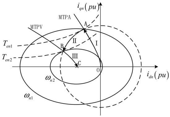
Figure 1.
Characteristic curves of PMSM.
According to the definition of the MTPA line and MTPV line, their expressions of can be obtained by the equal slope method. From (10), the tangent slope on the equal torque curve is:
From (11), the tangent slope on the current circle is:
From (12), the tangent slope on the voltage ellipse is:
Combining (13) and (14), the expression of the MTPA line can be obtained as:
Combining (10) and (15), the expression of the MTPV line can be obtained as:
When the motor runs at less than the critical base speed , it can simultaneously satisfy the current circle, voltage ellipse and MTPA curve equation. Combining (11), (12) and (16), the value of motor base speed can be solved:
When the weak magnetic region Ⅲ exists ( > 1) and the motor runs at the critical speed of region Ⅲ, the current circle, voltage ellipse and MTPV curve equation can be satisfied simultaneously. Combining (11), (12) and (17), the three-zone critical speed of the motor can be solved.
In summary, represents the working point of the PMSM in the d-q axis coordinate systems. When the PMSM is working, the working point can be expressed as a piecewise continuous function varying with speed. The operating point of region Ⅰ has nothing to do with speed, and region Ⅲ has nothing to do with the current.
3. The Proposed Control Method
3.1. Fixed SVPWM Modulation Index Algorithm
In the vehicle PMSM drive system integrated with the bidirectional DC/DC, the greater the boost of the bidirectional DC/DC converter, the greater the switching loss, the higher the DC bus voltage, and the greater the switching loss of the motor inverter. The higher the SVPWM modulation system at the same speed, the lower the voltage harmonic content and the lower the current harmonics of the motor output phase. The bidirectional DC/DC converter cannot always boost the bus voltage to the highest bus voltage, but automatically adjusts the DC bus voltage according to the operation needs of the latter motor.
According to (8) and (9), the back electromotive force of PMSM is proportional to the motor speed, so the minimum bus voltage required to maintain the current speed stability of the motor can be calculated by (8) and (9). As shown in Figure 2, when the rotational speed is lower than , the input voltage of the inverter is the battery voltage ; when the speed is above the base speed , the input voltage of the inverter is adjusted with the motor speed; when the rotational speed is higher than , the input voltage of the inverter is . Therefore, the input voltage of the inverter can be expressed as a piecewise continuous function varying with speed.
where is the basic speed of the motor when the input voltage of the inverter is the battery voltage, is the basic speed of the motor when the input voltage of the inverter is DC/DC, which can output the maximum voltage, is the safety margin of the voltage in the weak magnetic region, represents the maximum multiple of the boost of the drive system.
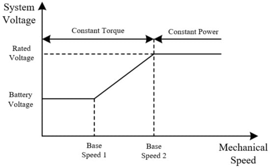
Figure 2.
Required system voltage with mechanical speed.
According to the above analysis, the dynamic regulation of bus voltage not only needs to consider the current motor running state but also needs to consider the voltage safety margin in the weak magnetic region, to avoid loss of control caused by current control output voltage saturation. However, the voltage safety margin is set by engineers with experience; it is difficult to quantitatively analyze its voltage size.
To achieve the above boost purpose, this paper proposes a method of fixed SVPWM modulation. By introducing SVPWM modulation, the motor back electromotive force and the safety margin of the weak magnetic area are quantified. SVPWW modulation can be expressed as the ratio of the motor back electromotive force to the inverter input voltage. The higher the SVPWM modulation is, the closer the input voltage of the inverter is to the motor back electromotive force and the more minor switching loss of the inverter. The input voltage of the inverter is composed of the voltage safety margin of the weak magnetic region and the required minimum bus voltage. Therefore, by setting a higher SVPWM modulation system, the low switching loss and phase current harmonics of the inverter are guaranteed. The voltage safety margin of the weak magnetic region is appropriate to avoid causing current loop saturation.
The SVPWM linear modulation system can be expressed as:
where the range of is 0–1, is the amplitude of the phase voltage, namely, the minimum bus voltage required to maintain the current speed stability of the motor, and is the DC bus voltage, namely, the input voltage of the inverter.
The transfer function diagram of the proposed SVPWM modulation method is shown in Figure 3. The output of the modulation control loop is the voltage given value of the bidirectional DC/DC.
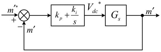
Figure 3.
Transfer function block diagram of the fixed SVPWM modulation method.
Where is the reciprocal of a given modulation ; is the voltage provided value of bidirectional DC/DC; is the reciprocal of voltage vector .
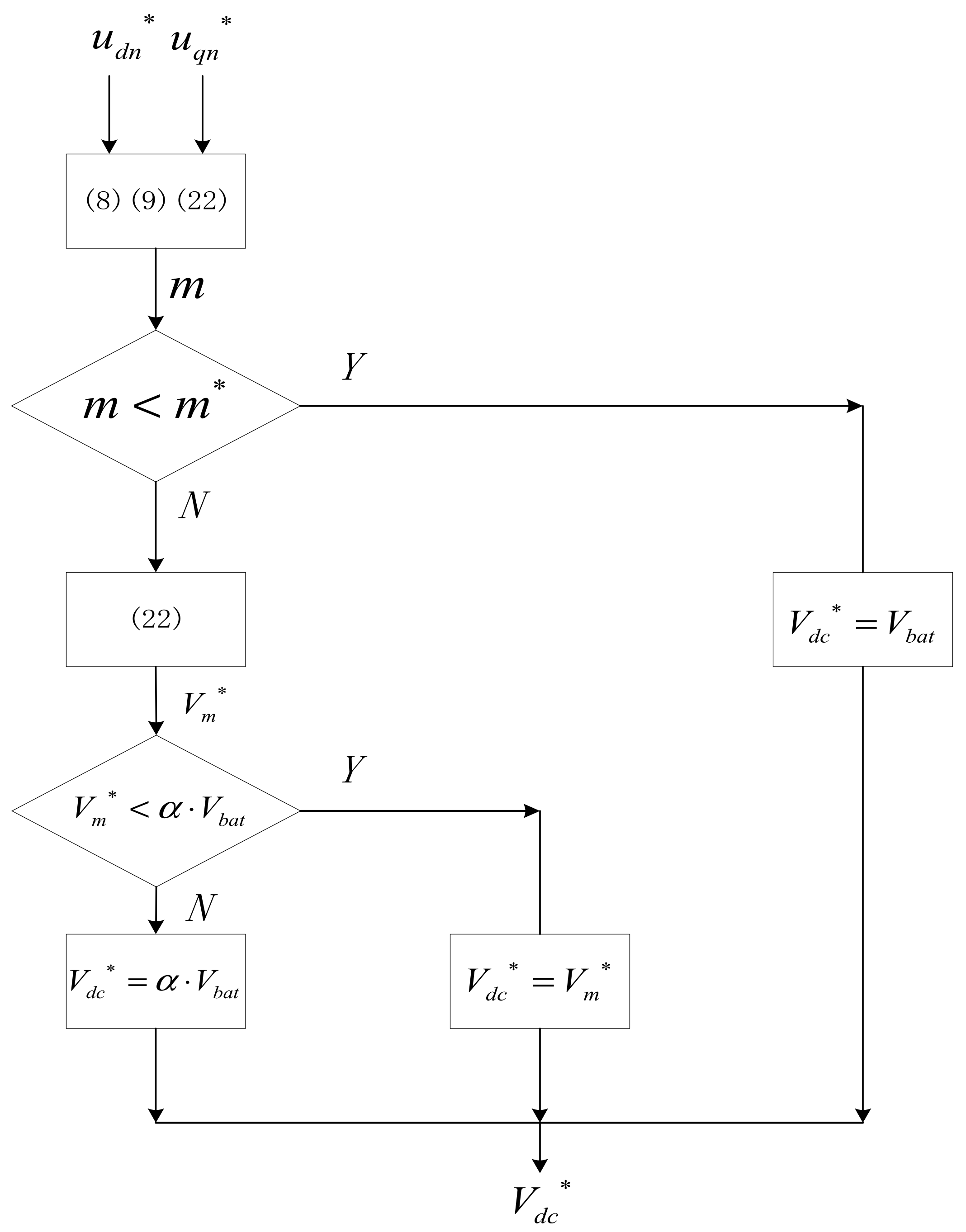
The control flow chart of the fixed SVPWM modulation method is given as shown in Figure 4. Firstly, to ensure the stability of the bus voltage adjustment area, the modulation system is set to , and the Simultaneous (8), (9) and (22) calculations of the SVPWM modulation system under the current-voltage operation condition are compared with the setting modulation system. If not exceeding, the output voltage is battery voltage. If more than, the constant, the SVPWM voltage regulation is carried out, and the bus voltage required for the motor operation condition to maintain the setting regulation is obtained by (22). When the required bus voltage reaches the maximum output voltage of DC/DC, the bus voltage remains the maximum.

Figure 4.
Control flow diagram of the fixed SVPWM modulation method.
3.2. Voltage Command Compensation Algorithm
From the analysis in Section 2.2, it can be concluded that when the motor speed is lower than the base speed , the working point of the motor is on the MTPA. When the speed is higher than the , in order to continue to rise, weak magnetic control must be used. In the weak magnetic region, the voltage vector amplitude is close to the output voltage limit of the inverter. In the transient process, the output voltage instruction of the current loop sometimes exceeds the output voltage limit of the inverter due to external interference and other factors. At this time, the d-q current loops are saturated and highly coupled, which affects the current following ability of the control loop, resulting in the increase of current harmonics and the imbalance of current. If serious, it will cause the system to shut down.
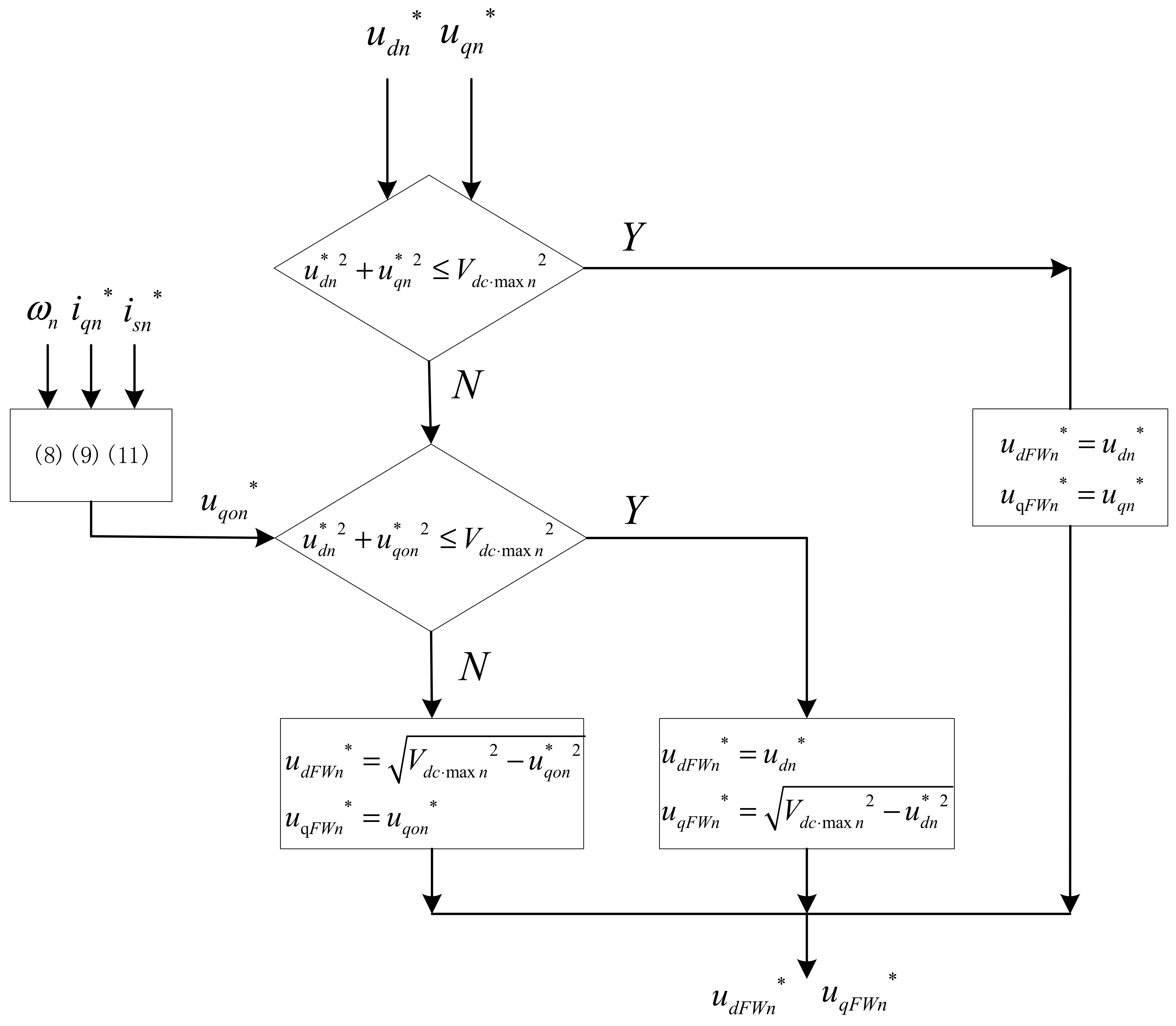
In this regard, this paper adopts a voltage instruction amplitude compensation algorithm, as shown in Figure 5, which is the control flow diagram of the algorithm. The current loop output voltage instruction amplitude is compared with the inverter output limit. If not exceeded, no compensation is needed; otherwise, the voltage instruction will be compensated. The q-axis expected voltage obtained by simultaneous Equations (8) and (9) and (11) replaces the q-axis voltage output by the current loop. If the corrected voltage instruction amplitude is still lower than the limit value, the d-axis voltage output by the current loop is compensated. This method has a certain inhibitory effect on the saturation of the output voltage instruction value of the current loop in the weak magnetic region.

Figure 5.
Control flow chart of voltage comment compensation.
4. Simulation and Experimental Analysis
4.1. Simulation Results and Analysis
To verify the effectiveness of the proposed strategy, the simulation model is established in MATLAB/Simulink. The parameters of PMSM are shown in Table 2, where the foremost parameters are to be defined in the per-unit system are and .
Table 2.
Motor Parameters.
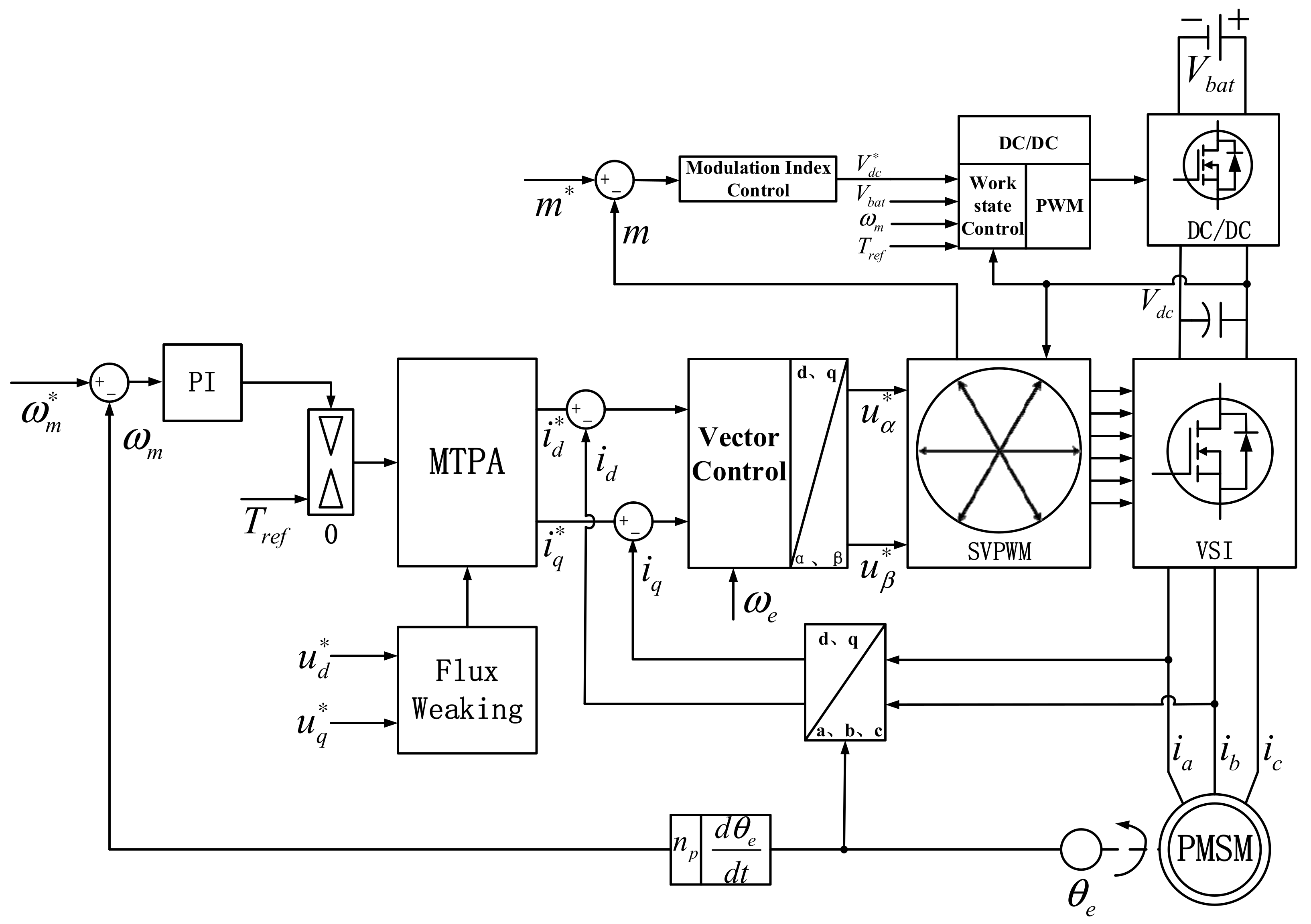
The motor drive topology of a traditional battery directly connected inverter is directly supplied by a battery with a rated voltage of 60 V. The motor drive topology of the inverter integrated with bidirectional DC/DC is provided by DC/DC, as shown in Figure 6. Considering the battery voltage and the withstanding voltage level of the MOSFET inverter, the output voltage range of the bidirectional DC/DC converter is 60 V–85 V. The modulation index control loop works in the linear modulation area of SVPWM. Considering the minimum operating voltage of the motor and the low harmonic distortion under the high modulation index, this paper sets the modulation index as 0.92.
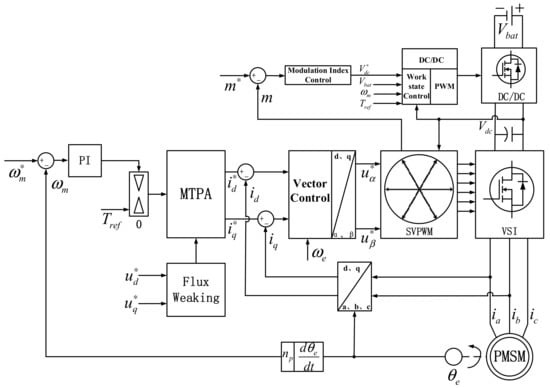
Figure 6.
Block diagram of the control strategy for motor drive topology with integrated bidirectional DC/DC.
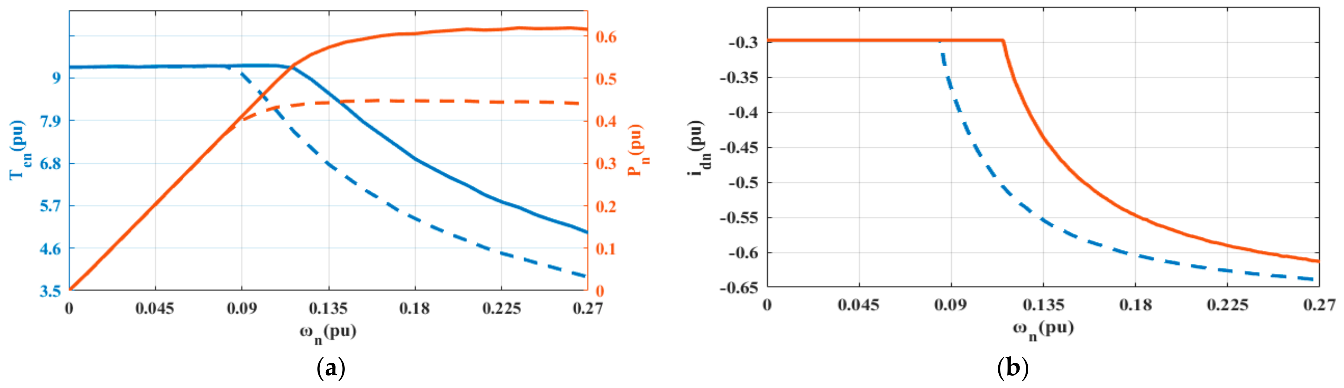
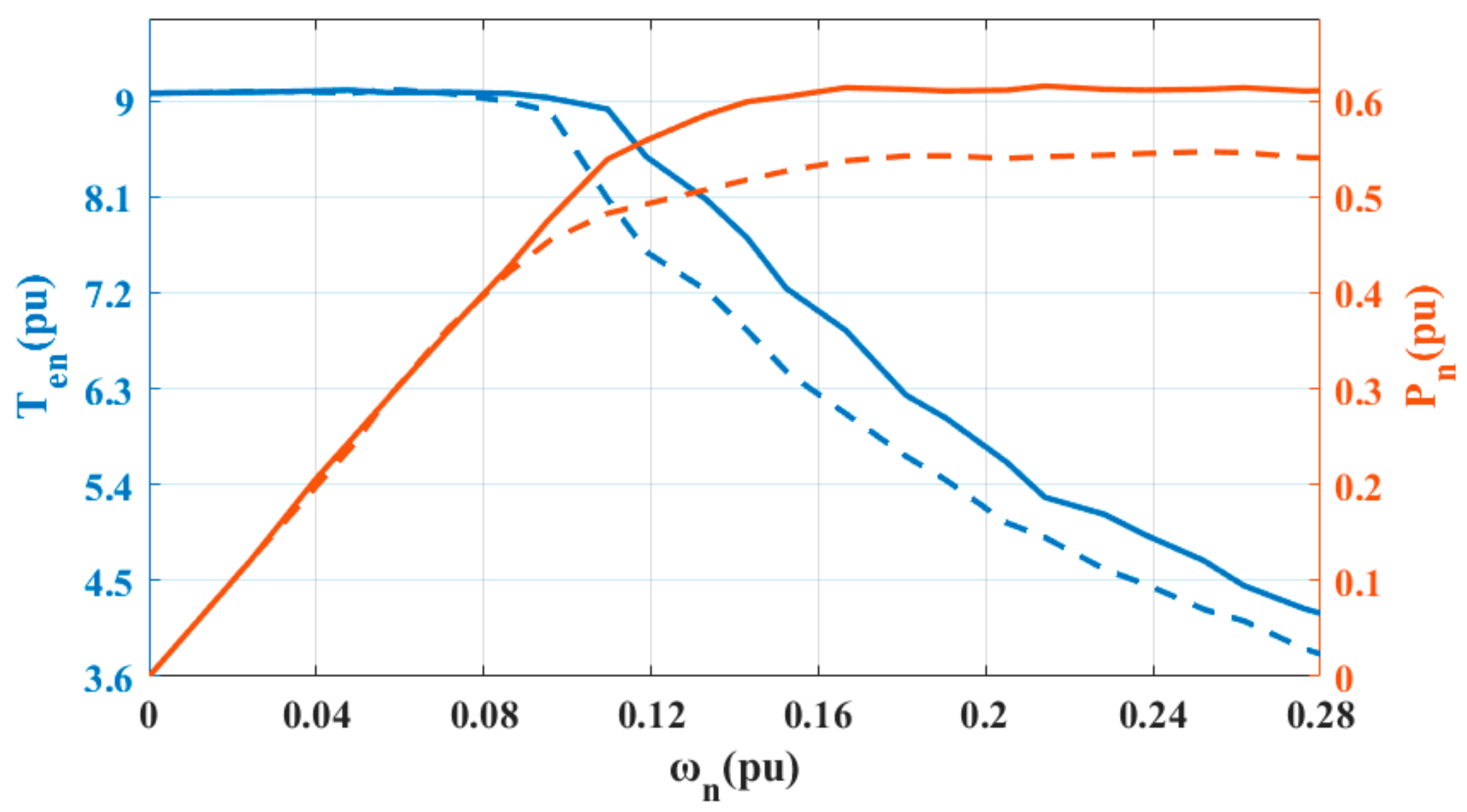
Figure 7 shows the external characteristic simulation of PMSM with traditional topology and bidirectional DC/DC topology. As shown in Figure 7a, under the traditional motor topology, p.u. begins to enter the weak magnetic region from the base velocity region. The output power of the constant power region is 0.54p.u. After the bidirectional DC/DC topology is added, p.u. enters the weak magnetic area, and the output power of the constant power region is 0.62p.u. The simulation results show that adding bidirectional DC/DC can expand the constant torque region of the motor, improve the output power of the motor in the constant power region and improve the driving performance of the motor. As shown in Figure 7b, at the same speed in the weak magnetic area, the bidirectional DC/DC topology has a smaller negative id current, which reduces the copper loss of the motor. At the same time, the motor can obtain a higher speed without running in the deep weak magnetic region, which ensures a wide speed range.
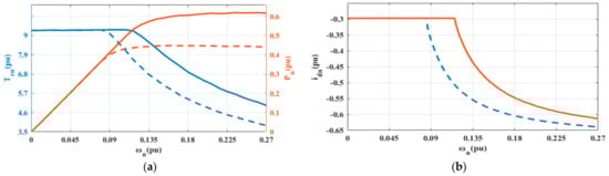
Figure 7.
External characteristic curve and negative id current of traditional topology (T1) and motor drive topology with bidirectional DC/DC (T2). (a) Torque-velocity curve (blue), power–velocity curve (red) of T1 (virtual line) and T2 (solid line). (b) Velocity-negative current id curve of T1 (virtual line) and T2 (solid line).
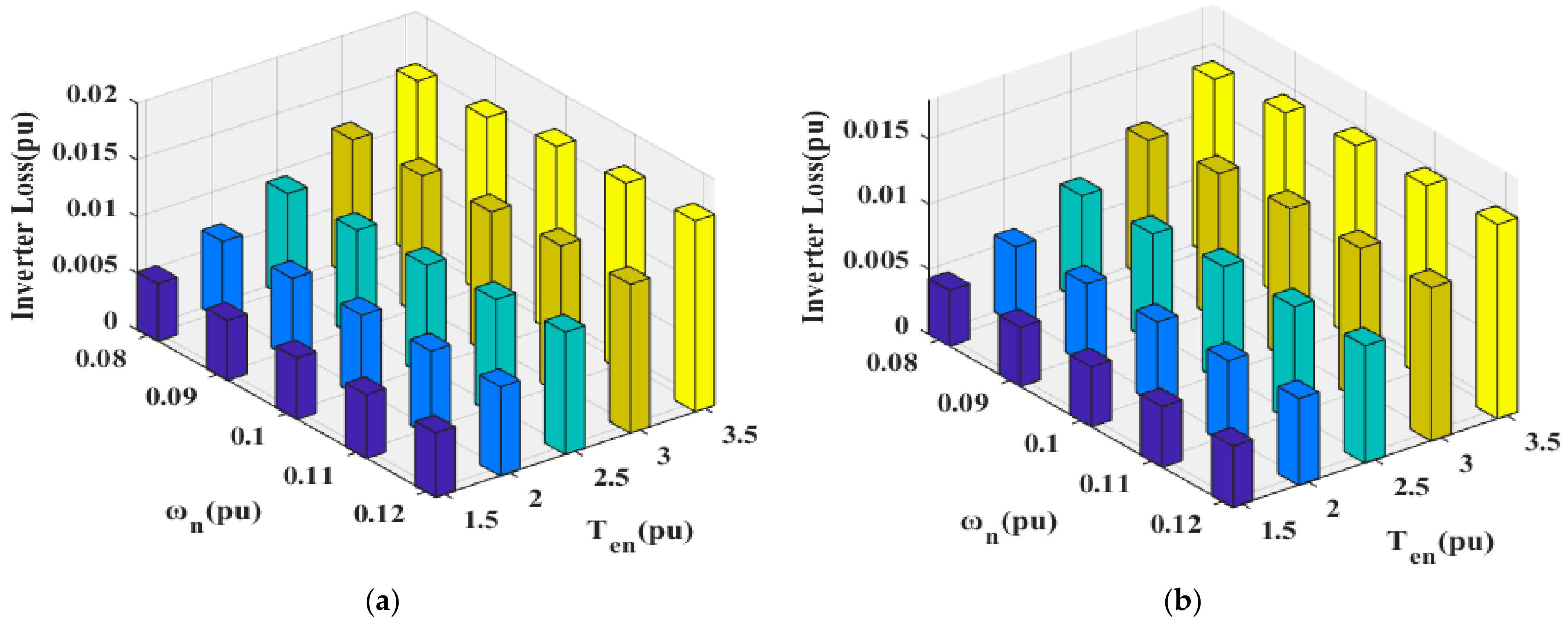
Figure 8 shows the inverter loss simulation of the traditional boost algorithm with bidirectional DC/DC topology and the proposed SVPWM boost algorithm. As shown in Figure 8a, under the traditional boost algorithm, the inverter loss is 0.015p.u. when the motor fundamental speed region p.u., p.u. and the inverter loss is 0.0155p.u. when the boost region p.u., p.u. As shown in Figure 8b, under the same motor working condition under the boost algorithm, the inverter losses are 0.014p.u. and 0.015p.u. The simulation results show that the boost algorithm reduces the inverter loss in the fundamental speed region and the boost region, it ensures the efficient output of the inverter.
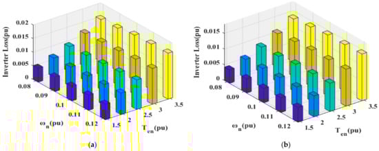
Figure 8.
Inverter loss of traditional boost algorithm and the proposed boost algorithm of SVPWM modulation scheme (a) traditional algorithm (b) fixed SVPWM modulation algorithm.
Figure 9 shows the simulation of the stator voltage d-axis component and three-phase current waveform before and after the voltage instruction compensation algorithm is added. As shown in Figure 9a, before the voltage command compensation, at 0.09 s it begins to enter the flux-weakening region from the base velocity region. At this time, the voltage spike of 0.2p.u. appears in the d-axis component of the stator voltage, resulting in the unbalanced three-phase current, as shown in Figure 9c. In Figure 9b, adding voltage instruction compensation, 0.09 s from the base speed region into the weak magnetic area, the stator voltage d axis component appears as a 0.02p.u. voltage spike, the three-phase current imbalance has been improved as shown in Figure 9d. The simulation results show that the voltage instruction compensation can effectively reduce the three-phase current imbalance when the motor enters the weak magnetic region from the base speed area and ensures the smooth operation of the motor.
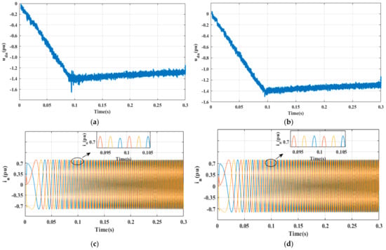
Figure 9.
The stator voltage d–axis component and three-phase current waveform before and after the voltage instruction compensation algorithm is added. (a) the former stator voltage d–axis component is added. (b) the latter stator voltage d–axis component is added. (c) the former three–phase current waveform is added. (d) the latter three–phase current waveform is added.
4.2. Experiment Results and Analysis
To further verify the effectiveness and feasibility of the proposed control strategy for the PMSM drive system integrated bidirectional DC/DC, an experimental platform is built, as shown in Figure 10. The motor used in the experiment has a deceleration mechanism, and the deceleration ratio is 8.33. The specific parameters are shown in Table 2.
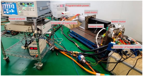
Figure 10.
Experimental platform of PMSM drive system.
Figure 11 shows the external characteristic experimental waveforms of the PMSM with traditional topology and bidirectional DC/DC topology. Under the traditional motor drive topology, when p.u., it begins to enter the flux-weakening region from the base velocity region, and the output power of the constant power region is 0.53p.u. After adding the bidirectional DC/DC topology, when p.u., it enters the flux-weakening area, and the output power of the constant power region is 0.61p.u. The experimental results show that adding bidirectional DC/DC can expand the constant torque area of the motor, improve the output power of the motor in the constant power area, and improve the driving performance of the motor. The feasibility of adding bidirectional DC/DC topology is verified.
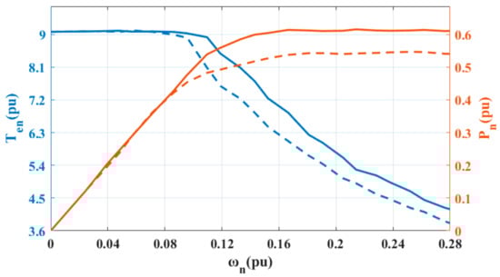
Figure 11.
Torque-speed curve (blue), power-speed curve (red) of traditional topology (virtual line) and adding bidirectional DC/DC topology (solid line).
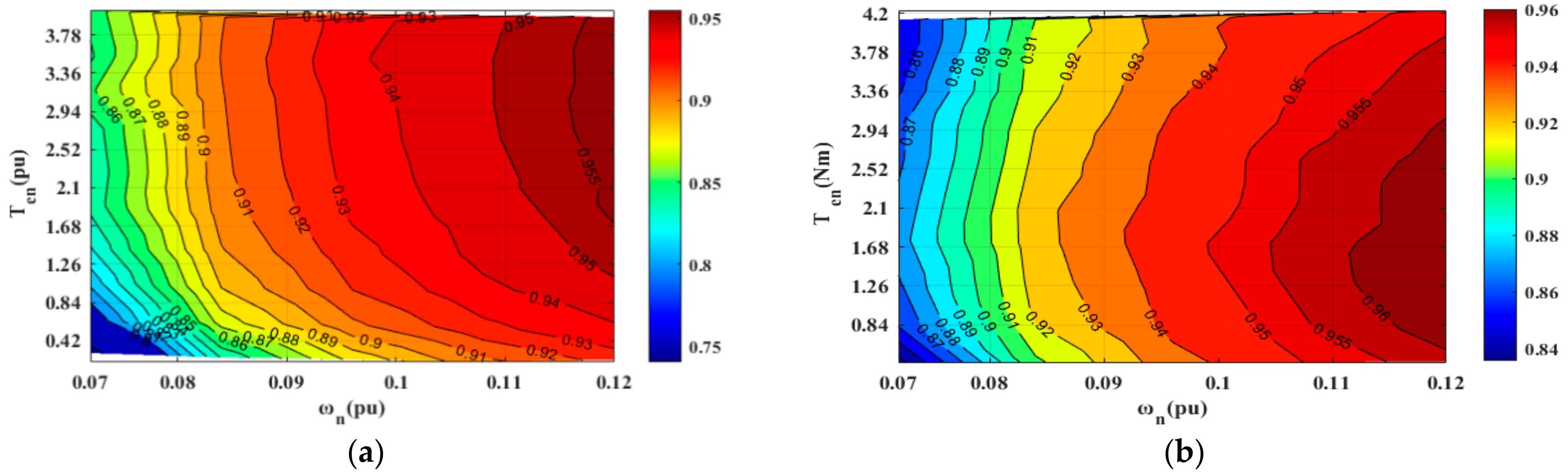
Figure 12 shows the inverter efficiency MAP experimental results of the traditional algorithm and the fixed SVPWM modulation algorithm. As shown in Figure 12a, when the traditional algorithm p.u., p.u. the inverter efficiency in the base speed region is 88%, and when p.u., p.u. the inverter efficiency in the boost region is 93%, and the proportion of inverter efficiency greater than 95% reaches 12.5%. As shown in Figure 12b, under the same working conditions, the efficiency of the inverter in the base speed region of the fixed SVPWM modulation algorithm is 90%, and the efficiency in the boost region is 94%. The proportion of the inverter efficiency greater than 95% reaches 30.1%. The experimental results show that the efficiency of the inverter in the base speed region and the boost region is increased by 2% and 1%, respectively. The area of the efficient region of the inverter is expanded by nearly 17.5%, indicating that the proposed algorithm can obtain a higher and more stable efficient region, which verifies the correctness of the theoretical analysis and simulation.
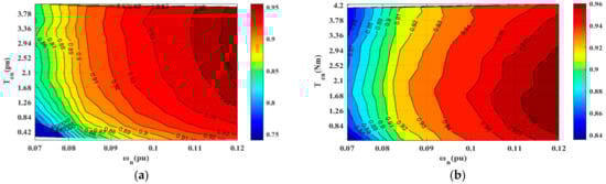
Figure 12.
The inverter efficiency MAP. (a) traditional algorithm. (b) fixed SVPWM modulation index algorithm.
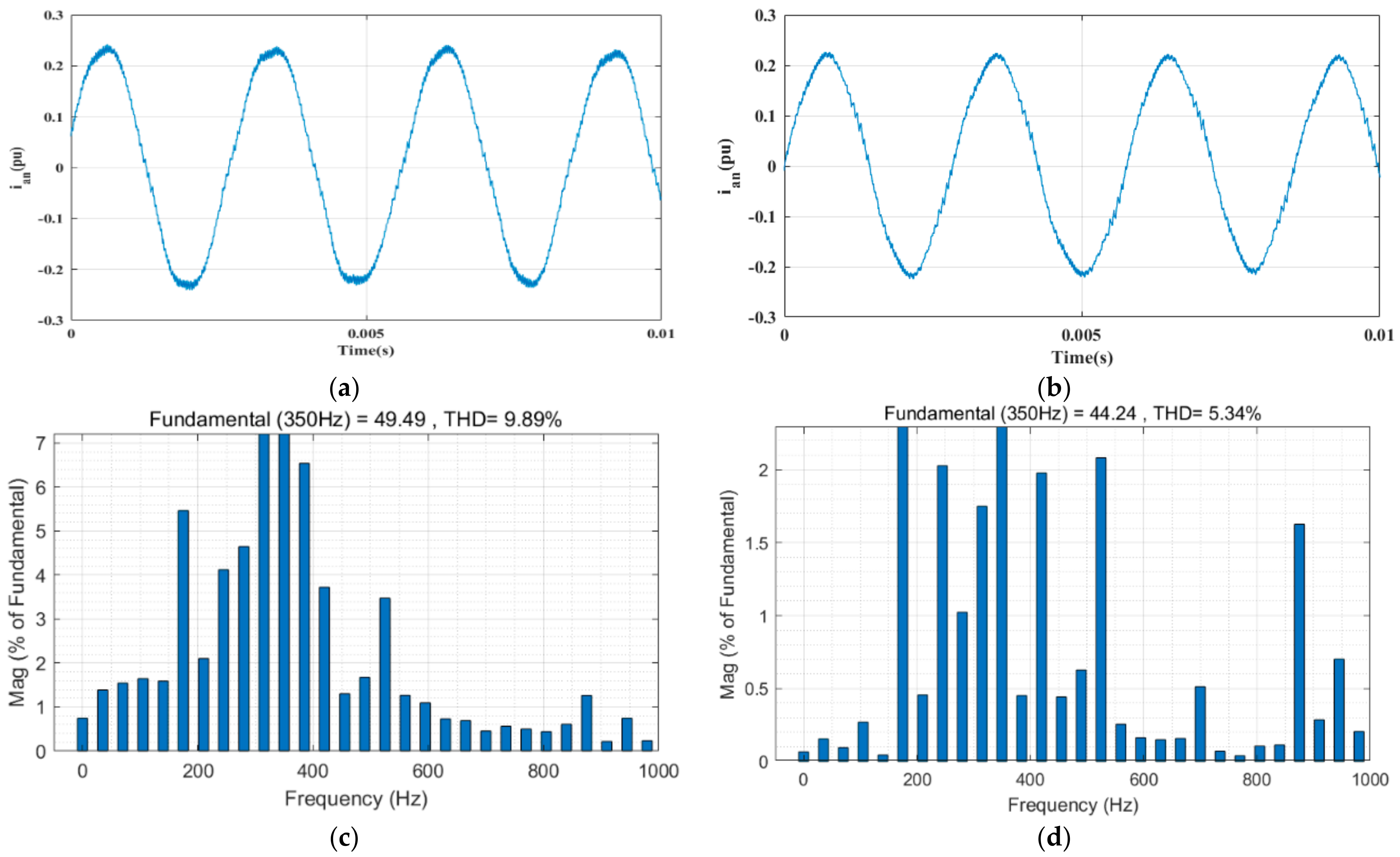
Figure 13 shows the experimental results of the phase A current waveform, and THD value before and after the voltage instruction compensation algorithm is added. as shown in Figure 13a,c, before adding voltage instruction compensation algorithm in the boost area p.u., p.u., the A-phase current waveform harmonic is larger and the waveform is unbalanced, and the THD value is 9.89%. As shown in Figure 13b,d, the harmonic and balance problems of the A-phase current waveform with the voltage instruction compensation algorithm under the same working conditions have been effectively improved, and the THD value is 5.34%. The experimental results show that the proposed algorithm can effectively reduce the current harmonics and improve the unbalanced current waveform, ensuring the control performance of the motor.
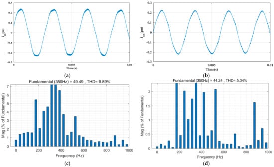
Figure 13.
A–phase current waveform and THD value before and after adding voltage instruction compensation algorithm. (a) adding pre–phase current waveform. (b) adding post–phase current waveform. (c) adding pre–phase current waveform THD value. (d) adding post–phase current waveform THD value.
The experimental results are verified with the theoretical and simulation results, reflecting the superiority and feasibility of the proposed SVPWM modulation and voltage command compensation method for PMSM drive control integrated with bidirectional DC/DC.
5. Conclusions
In this paper, a method based on fixed SVPWM modulation and voltage instruction compensation is proposed, which is used to integrate the bidirectional DC/DC permanent magnet synchronous motor (PMSM) drive control system to effectively reduce the switching loss of the inverter and the current harmonics in the weak magnetic region. By optimizing the input voltage of the inverter, the efficiency of the inverter is improved. Experiments show that the efficiency of the inverter in the base speed area is increased by 2% by using the fixed SVPWM modulation method, the efficiency of the inverter in the boost area is increased by 2%, and the efficient region of the inverter is expanded by 17.5%. The current harmonic in the weak magnetic area is reduced by 4.55% by using the voltage instruction compensation method, which proves the effectiveness and feasibility of the proposed algorithm.
Author Contributions
For Conceptualization, D.L. and X.G.; methodology, D.L.; software, D.L., F.C. and R.C.; validation, D.L., X.G. and Y.L.; formal analysis, D.L.; investigation, D.L.; resources, X.G. and Z.L.; data curation, D.L.; writing—original draft preparation, D.L.; writing—review and editing, R.W. and Z.L.; visualization, D.L.; supervision, R.W.; project administration, X.G.; funding acquisition, X.G. All authors have read and agreed to the published version of the manuscript.
Funding
This work was supported in part by the National Natural Science Foundation of China under Grant 52175051, in part by the Xiamen Science and Technology Project—University Research Institute Industry–University–Research Project—under Grant 3502Z202003037, and in part by the Science and Technology Innovation Team of Fujian Province Universities (Industrialization Project)—Power Semiconductor Device and Electric Drive Technology Innovation Team under Grant 605-5J120019.
Conflicts of Interest
The authors declare no conflict of interest.
References
- Ivanchev, J.; Fonseca, J.; Knoll, A. Electrification and automation of road transport: Impact analysis of heat and carbon emissions for singapore. In Proceedings of the 2020 IEEE 23rd International Conference on Intelligent Transportation Systems (ITSC), Rhodes, Greece, 20–23 September 2020; pp. 1–8. [Google Scholar]
- Ibanez, F.M.; Florez, A.M.B.; Gutiérrez, S.; Echeverrría, J.M. Extending the Autonomy of a Battery for Electric Motorcycles. IEEE Trans. Veh. Technol. 2019, 68, 3294–3305. [Google Scholar] [CrossRef]
- Pellegrino, G.; Vagati, A.; Guglielmi, P.; Boazzo, B. Performance Comparison Between Surface-Mounted and Interior PM Motor Drives for Electric Vehicle Application. IEEE Trans. Ind. Electron. 2012, 59, 803–811. [Google Scholar] [CrossRef] [Green Version]
- Sarigiannidis, A.G.; Beniakar, M.E.; Kladas, A.G. Fast Adaptive Evolutionary PM Traction Motor Optimization Based on Electric Vehicle Drive Cycle. IEEE Trans. Veh. Technol. 2017, 66, 5762–5774. [Google Scholar] [CrossRef]
- Laskaris, K.I.; Kladas, A.G. Internal Permanent Magnet Motor Design for Electric Vehicle Drive. IEEE Trans. Ind. Electron. 2010, 57, 138–145. [Google Scholar] [CrossRef]
- Wang, Y.; Li, Y.; Huang, X.; Fang, Y.; Ma, J. Comparison of direct-drive permanent-magnet synchronous motor and permanent-magnet flux-modulated motor for electric vehicles. In Proceedings of the 2017 20th International Conference on Electrical Machines and Systems (ICEMS), Sydney, NSW, Australia, 11–14 August 2017; pp. 1–5. [Google Scholar]
- Akar, F.; Tavlasoglu, Y.; Ugur, E.; Vural, B.; Aksoy, I. A Bidirectional Nonisolated Multi-Input DC–DC Converter for Hybrid Energy Storage Systems in Electric Vehicles. IEEE Trans. Veh. Technol. 2016, 65, 7944–7955. [Google Scholar] [CrossRef]
- Lin, Y.S.; Hu, K.W.; Yeh, T.H.; Liaw, C.M. An Electric-Vehicle IPMSM Drive with Interleaved Front-End DC/DC Converter. IEEE Trans. Veh. Technol. 2016, 65, 4493–4504. [Google Scholar] [CrossRef]
- Zhang, Y.; Gao, Y.; Zhou, L.; Sumner, M. A Switched-Capacitor Bidirectional DC–DC Converter with Wide Voltage Gain Range for Electric Vehicles with Hybrid Energy Sources. IEEE Trans. Power Electron. 2018, 33, 9459–9469. [Google Scholar] [CrossRef]
- Gong, C.; Hu, Y.; Wen, H.; Chen, G.; Li, W.; Gao, J. Reliable Winding-Based DC-Bus Capacitor Discharge Technique Over Full-Speed Range for IPMSM Drive in Electric Vehicles Without Position Sensor. IEEE Trans. Ind. Electron. 2020, 67, 8131–8142. [Google Scholar] [CrossRef]
- Elsayad, N.; Moradisizkoohi, H.; Mohammed, O.A. A New Hybrid Structure of a Bidirectional DC-DC Converter with High Conversion Ratios for Electric Vehicles. IEEE Trans. Veh. Technol. 2020, 69, 194–206. [Google Scholar] [CrossRef]
- Beraki, M.W.; Trovão JP, F.; Perdigão, M.S.; Dubois, M.R. Variable Inductor Based Bidirectional DC–DC Converter for Electric Vehicles. IEEE Trans. Veh. Technol. 2017, 66, 8764–8772. [Google Scholar] [CrossRef]
- Zhang, Y.; Cheng, X.F.; Yin, C.; Cheng, S. A Soft-Switching Bidirectional DC–DC Converter for the Battery Super-Capacitor Hybrid Energy Storage System. IEEE Trans. Ind. Electron. 2018, 65, 7856–7865. [Google Scholar] [CrossRef]
- Howlader, A.M.; Urasaki, N.; Senjyu, T.; Yona, A.; Saber, A.Y. Optimal PAM Control for a Buck Boost DC-DC Converter with a Wide-Speed-Range of Operation for a PMSM. J. Power Electron. 2010, 10, 477–484. [Google Scholar] [CrossRef] [Green Version]
- Yu, C.; Tamura, J.; Lorenz, R.D. Control method for calculating optimum DC bus voltage to improve drive system efficiency in variable DC bus drive systems. In Proceedings of the 2012 IEEE Energy Conversion Congress and Exposition (ECCE), Raleigh, NC, USA, 15–20 September 2012; pp. 2992–2999. [Google Scholar]
- Lemmens, J.; Driesen, J.; Vanassche, P. Dynamic DC-link voltage adaptation for thermal management of traction drives. In Proceedings of the 2013 IEEE Energy Conversion Congress and Exposition, Denver, CO, USA, 15–19 September 2013; pp. 180–187. [Google Scholar]
- Yamamoto, K. Power loss reduction and optimum modulation index of PWM inverter with voltage booster for permanent magnet synchronous motor drive. In Proceedings of the 2000 Conference Rec. IPEC, Tokyo, Japan, 3–7 April 2000; pp. 147–152. [Google Scholar]
- Chen, K.; Sun, Y.; Liu, B. Interior Permanent Magnet Synchronous Motor Linear Field-Weakening Control. IEEE Trans. Energy Conversion 2016, 31, 159–164. [Google Scholar] [CrossRef]
- Ding, D.; Wang, G.; Zhao, N.; Zhang, G.; Xu, D. Enhanced Flux-Weakening Control Method for Reduced DC-Link Capacitance IPMSM Drives. IEEE Trans. Power Electron. 2019, 34, 7788–7799. [Google Scholar] [CrossRef]
- Wang, S.; Kang, J.; Degano, M.; Galassini, A.; Gerada, C. An Accurate Wide-Speed Range Control Method of IPMSM Considering Resistive Voltage Drop and Magnetic Saturation. IEEE Trans. Ind. Electron. 2020, 67, 2630–2641. [Google Scholar] [CrossRef]
- Sepulchre, L.; Fadel, M.; Pietrzak-David, M.; Porte, G. MTPV Flux-Weakening Strategy for PMSM High Speed Drive. IEEE Trans. Ind. Appl. 2018, 54, 6081–6089. [Google Scholar] [CrossRef]
- Zhang, X.; Wang, B.; Yu, Y.; Zhang, J.; Dong, J.; Xu, D. Circular Arc Voltage Trajectory Method for Smooth Transition in Induction Motor Field-Weakening Control. IEEE Trans. Ind. Electron. 2021, 68, 3693–3706. [Google Scholar] [CrossRef]


Publisher’s Note: MDPI stays neutral with regard to jurisdictional claims in published maps and institutional affiliations. |
© 2022 by the authors. Licensee MDPI, Basel, Switzerland. This article is an open access article distributed under the terms and conditions of the Creative Commons Attribution (CC BY) license (https://creativecommons.org/licenses/by/4.0/).