Abstract
This paper presents a filterless sensorless control scheme with an optimized time sequence based on high-frequency (HF) square-wave voltage injection for a five-phase interior permanent magnet machine (IPMSM) drive. To avoid the utilization of low-pass filters (LPFs) in signal processing, an effective method without filters is proposed in this paper. Moreover, the cross-coupling magnetic saturation is analyzed and the online position error compensation is applied based on the offline measurements and finite-element analysis (FEA). Besides, compared with the conventional time sequence of senseorless control, the proposed optimized time sequence can eliminate the additional position estimation error caused by the time delay in digital implementation. Numerical simulations and experiments with a 2-kW five-phase IPMSM are carried out. The results verify the feasibility and effectiveness of the proposed sensorless control scheme with an optimized time sequence adopted by the IPMSM drives.
1. Introduction
Because of high torque density, excellent dynamic performance and wide adjustment speed range, the interior permanent magnet synchronous motors (IPMSMs) have been extensively employed in modern industrial applications, including aerospace aircraft, electric vehicles and hybrid renewable power systems [1,2,3,4]. In these applications, the position sensor for IPMSM drives, which fails easily in rigorous working environments, can be eliminated by sensorless control scheme considering cost reduction and reliability enhancement.
Tremendous effort has been invested in sensorless control in the last few decades. Generally, the sensorless control methods can be mainly classified into the following two categories: fundamental excitation based methods and external signal injection excitation based methods The former exploits the back electromotive force (EMF) or flux linkage to extract and estimate the rotor position information [5]. These methods are widely applied in medium and higher speed regions, while they fail at the standstill and low speed causes due to the small signal-to-noise ratio (SNR) of EMF signal [6]. To expand the sensorless control into the standstill and low speed range, the latter are adopted to obtain the rotor position information by external signal injection excitation. In terms of the types of injected signals, the mainstream signal injection methods can be roughly categorized as follow:
- (1)
- Use low-frequency signal injection [7,8,9].
- (2)
- Use HF rotational sinusoidal voltage injection (RSVI) [10,11].
- (3)
- Use HF pulsing signal injection such as sinusoidal voltage injection (SVI) [12,13,14] or square-wave voltage injection (SWVI) [15,16,17,18,19,20,21,22,23,24].
The first kind of method can effectively reduce the audible noise caused by the additional HF signal. However, the accuracy of position estimation will significantly decrease due to the low injected frequency, which need some additional auxiliary measures to enhance the estimation performance. The second kind of method uses HF sinusoidal voltages to inject into the stationary reference frame (SRF), which can cause inevitable torque vibration due to the fluctuations in the q-axis current [18]. For the third type of method, similar to the RSVI method, the application of the low-pass filters (LPFs) in HF pulsing SVI method limits the dynamic bandwidth of the system. In [19], the bandwidth of the speed loop is limited to a few hertz with sinusoidal signal injection, which makes it difficult to meet the requirements of high-performance drive. Moreover, the highest frequency of the injected sinusoidal signal is limited to about 1/10 of the carrier wave frequency [20]. Different from RSVI and pulsing SVI, the injection frequency of SWVI method can be increased up to the carrier frequency. Besides, the cutoff frequency of LPFs for fundamental frequency (FF) current extraction in SWVI method can be set higher, which effectively enhances the bandwidth of the drive system. For these reasons, the HF SWVI method can be considered as the optimal option for sensorless IPMSM drives in low speed regions. Nevertheless, the accuracy of position estimation in the HF SWVI method is still insufficient since it suffers from the position angle error caused by the cross-coupling magnetic saturation, inverter nonlinearity, and digital time-delay effect [21,22,23,24].
Numerous studies have been implemented to address these problems. To compensate for the position errors due to the cross-coupling effects, FEA [25], structured neural network, and offline measurements [26,27,28] are adopted. In [21,22] and [29], the nonlinearity effects of the inverter are analyzed, and related compensation measures are also proposed. However, there is a relatively small body of literature that is concerned with the digital time-delay in position sensorless control.
The two main contributions of this paper can be summarized as follows:
- (1)
- To avoid the utilization of LPFs in signal processing, the filterless signal processing method is proposed, which can enhance the system bandwidth.
- (2)
- The digital time delay in sensorless control is discussed, and an optimized time sequence is proposed, which can eliminate the additional position estimation error caused by the digital time delay.
Besides, to attenuate the effect of cross-coupling magnetic saturation, the online position error compensation is adopted based on FEA and offline measurements. Both simulations and experiment results are illustrated to demonstrate the effectiveness of the proposed method.
The rest of this paper is outlined as follows. In Section 2, the basic principles of the filterless HF SWVI method for a five-phase IPMSM drive are analyzed. In Section 3, the digital time delay and cross-coupling magnetic saturation in sensorless control is discussed, and rated compensation strategies are also adopted to enhance the accuracy of position estimation. In Section 4, the proposed sensorless scheme is verified by both simulation and experimental results. Finally, conclusions are given in Section 5.
2. Filterless HF SWVI Scheme for IPMSM Drive
2.1. Mechanism of HF SWVI Scheme
To facilitate the control of the five-phase IPMSM, the natural coordinate frame ABCDE can be decomposed into three mutually orthogonal spaces by means of coordinate transformation: fundamental space d–q, third harmonic space d3–q3, and zero-sequence space [1]. The first two spaces are the synchronous rotating reference frame (RRF) with different rotational speeds. Besides, the third harmonic component does not participate in the electromechanical energy conversion. Meanwhile, due to the star connection of the stator winding, the neutral point current in the zero-sequence space is zero, which can be neglected. Consequently, the stator voltage equation of the five-phase IPMSM can be demonstrated as
where ud,q and id,q are the voltage and current vectors, respectively; Rs is the stator resistance; Ld and Lq are the inductances on the d-axis and q-axis, respectively; ωe is the electrical angular speed; Ψf is the flux linkage; p = d/dt is a differential operator of time. The subscript “3” represents the corresponding components in the third harmonic spaces. It is worth noting that the HF SWVI method only acts on the fundamental space d-q and does not involve the third harmonic space d3–q3.
Since the injection frequency is much higher than the fundamental frequency and the motor operates at zero- and low-speed region, (1) can be simply depicted as
where the subscript “h” is the corresponding HF component.
Then, the currents variation due to the injected voltage in the estimated rotating frame (ERF) can be shown as
where the superscript “^” is the corresponding component in the ERF. LΣ and Ldif are defined as LΣ ≡ Ld + Lq and Ldif ≡ Lq − Ld, respectively. θerr is the rotor position estimation error, which is defined as the difference between the actual position θe and the estimated position .
The HF square-wave voltage signal injected into the ERF can be expressed as
where Th is the period of HF voltage signal. After substituting (4) into (3), and de-symbolizing the envelope curves of induced HF current, the amplitude of the induced HF current in the ERF can be obtained as
As can be seen, in (5) contains the position error information. Hence, when this position error is sufficiently small and Ldif ≠ 0, the error signal can be linearized as (6) after normalization.
where Knorm is the normalization coefficient and can be presented as
Then, a PI-type phase-locked loop (PLL) in Figure 1 can be applied to estimate the rotor position and speed.
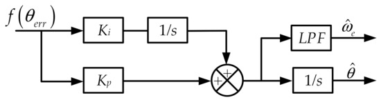
Figure 1.
PI-type software phase-locked loop.
2.2. Proposed Filterless Signal Processing Method
There are some certain drawbacks associated with the application of filters in signal processing, e.g., an inevitable processing delay, bandwidth limitation, and performance qualities diminishment. Hence, in this paper, a signal processing method without filters is proposed. Figure 2 illustrates the proposed filterless signal processing method based on HF SWVI scheme. In Figure 2, the nearest four vectors SVPWM (NFV-PWM) [30] is applied to the SVPWM control of five-phase inverter, which can effectively suppress the third harmonic. The FF current is obtained by sampling at zero-crossing point, meanwhile the induced HF current of q-axis is extracted by simple algebraic operation.
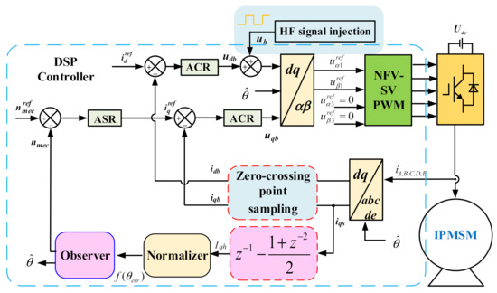
Figure 2.
Block diagram of the proposed filterless signal processing method based on HF SWVI scheme.
Figure 3 illustrates the time sequence of the injected square-wave voltage and the induced HF current, which shows the details of the proposed signal processing methods. In Figure 3, the induced HF current is sampled four times during one HF square-wave voltage period. Besides, the induced HF current has a fixed zero-crossing point; therefore, the sampling current obtained at the zero-crossing point is the FF current. Since the frequency of the injected square-wave signal is much higher than the frequency of FF current, the growth rate of FF current in the one carrier wave period (Tc) can be regarded as constant [31,32], while the high-frequency current growth rate is reversed. Besides, the update frequency of FF voltage is set to be twice the HF injected signals frequency. According to the above analysis, the currents at different sampling instant can be expressed as
where the subscript “b” is the corresponding FF component, the subscript “s” is the corresponding sampling component, and the subscript “ki” means the corresponding component at ki sampling instant (i = 0,1,2…). For any sampling instant, the sampling current at d-or q-axis contains the FF current and the induced HF current .
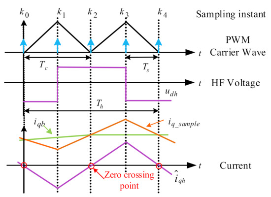
Figure 3.
Time sequence of the injected HF square-wave voltage and the induced HF current.
The obtained FF current can be directly used for the current loop without passing through a low-pass filter or notch filter. Furthermore, the induced HF current is used to observing rotor position and velocity. The filterless signal processing method is suitable for digital control, which can achieve high performance during sensorless operation.
3. Analysis and Compensation of Position Estimation Error
Since the digital time delay and cross-coupling magnetic saturation will affect the position estimation accuracy of sensorless control, we will give the corresponding analysis and compensation strategies for these two problems in this section.
3.1. Analysis of Digital Time Delay Effect
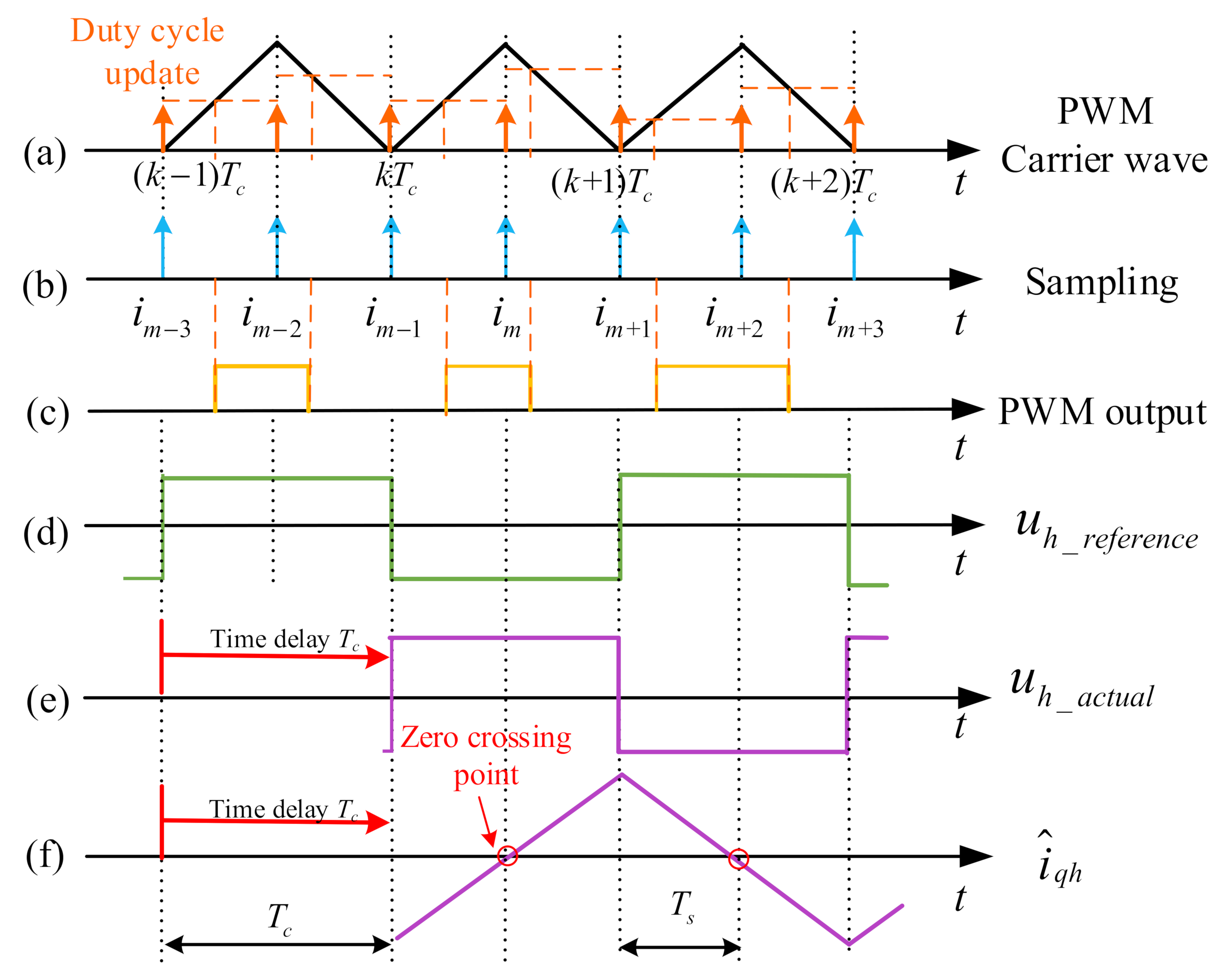
In full-digital control system of IPMSM drives, there is an inevitable execution time delay, which is commonly one sampling period. Furthermore, the digital PWM logic also produces a further time delay [33]. The delay caused by the PWM is relevant to the strategy of generating PWM signals in a digital way. Figure 4a–c illustrates a digital PWM output mode, which is called the double current sampling and double PWM duty cycle update (DSDU) mode. Under this mode, the update frequency of duty cycle is set to be twice the carrier wave frequency, and one sampling time delay Ts is a good approximation for implementing digital PWM logic. This two sampling period time delay (2Ts or 1Tc) cannot be neglected when considering the frequency of injected HF signal is close to the PWM switching frequency. Meanwhile, in realization, the actual injected HF voltage lags behind the HF signal reference, which will produce an additional position estimation error [29]. Figure 4d illustrates the HF voltage reference. The actual HF voltage and induced current considering one carrier cycle time delay are shown in Figure 4e,f. In this part, the position estimation error caused by digital time delay is discussed and a compensation scheme based on optimized time sequence is proposed.
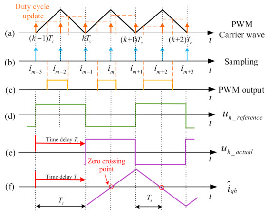
Figure 4.
Waveforms of DSDU mode with the digital time delay: (a) PWM carrier wave; (b) Sampling; (c) PWM output; (d) Ideal injected HF voltage; (e) Actual injected HF voltage; (f) HF induced current in the estimated q- axis.
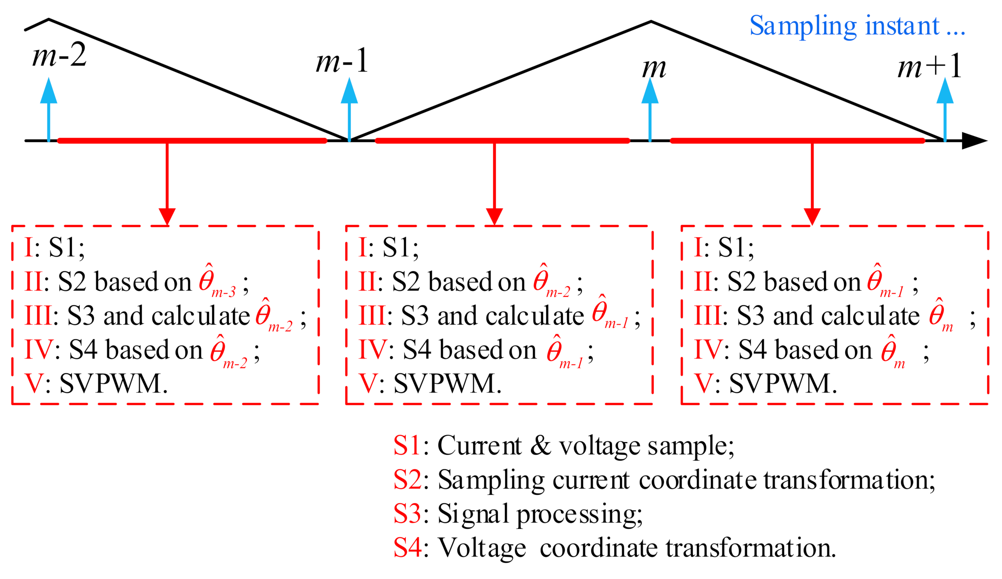
Figure 5 illustrates the conventional time sequence for sensorless control based on the DSDU mode. After each PWM interrupt is triggered, the DSP will sequentially execute the operations of I~V. In every sampling period, the coordinate transformation of sampling current is based on the estimated position angle, which is obtained in the previous sampling period. The subscript “m” is the corresponding position angle in the m th sampling instant.

Figure 5.
Conventional time sequence for sensorless control based on DSDU mode.
During the sampling instant (m−1, m), the HF voltage of the inverter output in the real RRF can be expressed as
where the TPark and are the Park coordinate transformation and its inverse transformation respectively.
In (9), since the θe(t) varies from (m−1) to (m) sampling instant, the HF voltage in the real RRF also varies with time, and the induced HF current amplitude at the (m) sampling instant can be shown as
Consider that θe(t) changes very slowly during the (m−1) to (m) sampling period, which can be replaced by its average value for the integral in (10). Here, and the HF current amplitude in (14) can be deduced as
Then the amplitude of the HF current in the ERF at the (m) sampling instant can be deduced as
where θe,m is the real electrical angle at (m) sampling instant. Therefore, the amplitude of q-axis HF current in the ERF can be shown in (13).
Compared with (5), the coefficient of the LΣ term in (13) does not equal to zero, which can be defined as the digital time-delay error. When the PLL converges to zero steadily, i.e., , the rotor position estimation error can be expressed as
where λ = Lq/Ld is the saliency rate. The digital time-delay error in (13) brings the steady-state error, which is proportional to the speed and inversely proportional to the saliency rate.
3.2. Compensation Strategy for Digital Time-Delay
As can be seen from (13) and (14), the digital time-delay error is dependent on the motor parameters and speed, which is difficult to be directly compensated. In order to attenuate the time-delay effect, an optimized time sequence is proposed in Figure 6. Compared with the conventional time sequence, the optimized time sequence compensates the estimated angle in the step II, i.e., for any (m) sampling instant, the sampling current coordinate transformation is based on
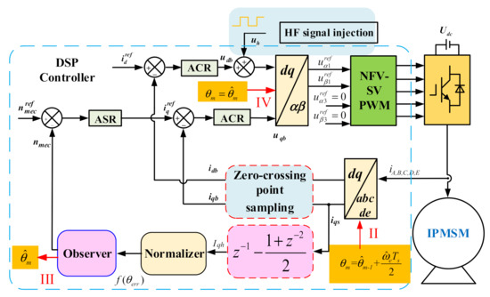
Figure 6.
Block diagram of the optimized time sequence for (m) sampling instant.
For (m−1) sampling instant, (15) can be reformulated as
Therefore, substituting (16) into (13), the HF current in the ERF can be expressed as
As shown in (17), the digital time-delay error in (13) is eliminated. According to the optimized time sequence, the position estimation error in (17) when the PLL is steady-state convergence can be obtained as
As is shown in (18), the observed position estimation error is negative, which indicates that the advanced estimation is realized.
3.3. Compensation for Cross-Coupling Magnetic Saturation
The cross-coupling magnetic saturation between the d- and q-axis can significantly influence the accuracy of rotor-position estimation in sensorless control. When the cross-coupling magnetic saturation is considered, (2) can be rewritten as
where Ldq is the cross-coupling inductance. Therefore, the amplitude of the HF q-axis current in the ERF can be expressed as [26]
where φdq = tan−1 (Ldq/Ldif). Hence, the position estimation error caused by the cross-coupling inductance can be given as
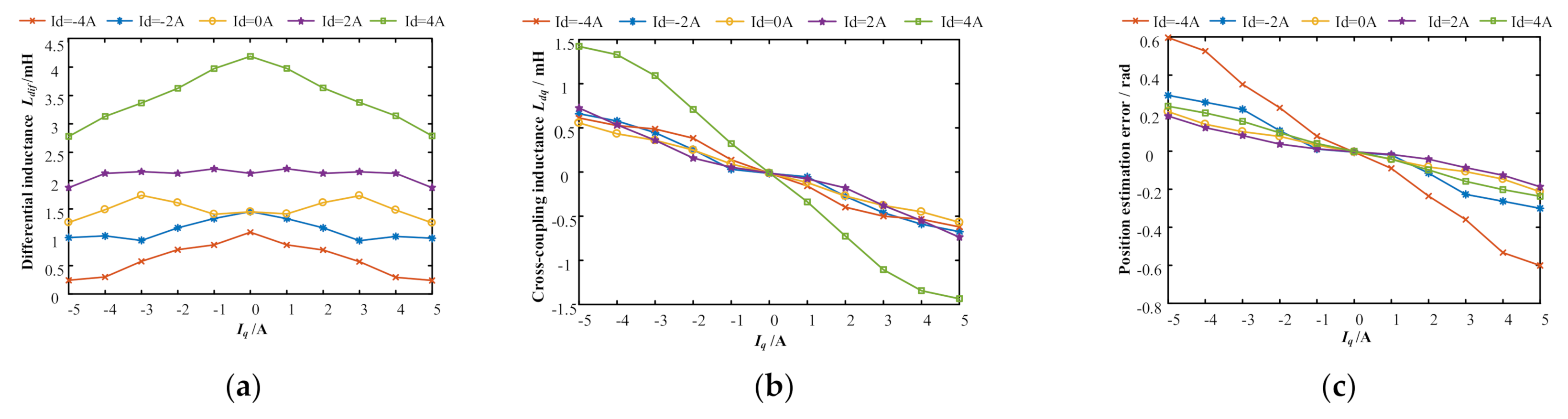
As can be seen, the position estimation error contains a phase shift of 0.5φdq. Figure 7 shows the finite element analysis (FEA) results of Ldif, Ldq and θerr under different d- and q-axis current condition. As can be seen from Figure 7c, the position estimation error caused by cross-coupling magnetic saturation can increase with the amplitude of the q-axis current.
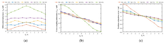
Figure 7.
FEA results with different d- and q-axis current: (a) Differential inductance Ldif; (b) Cross-coupling inductance Ldq; (c) Position estimation error θerr.
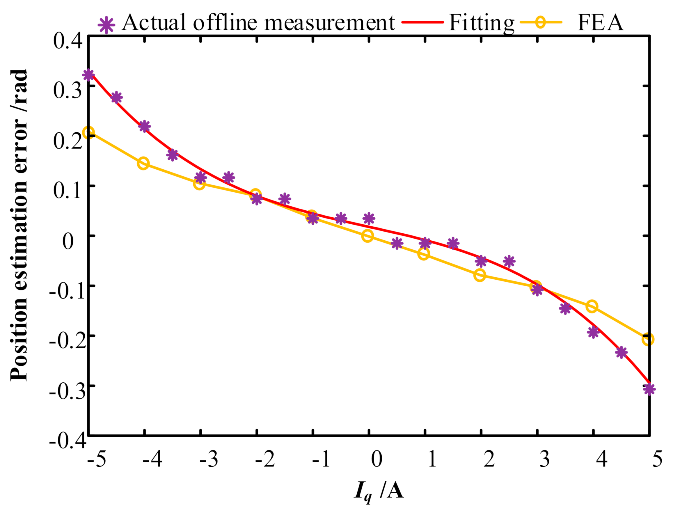
To further accurately eliminate the effect of cross-coupling magnetic saturation, in this paper, the offline measurement is applied to eliminate the additional position estimation error. For the prototype machine, the offline measured position estimation error angle when Id = 0 is shown in Figure 8. Compared with the FEA results, the fitting cure obtained by offline measurements only has slight deviation, and the overall tendency remains the same. Therefore, the fitting curve can be employed for online position estimation compensations, which can be expressed as
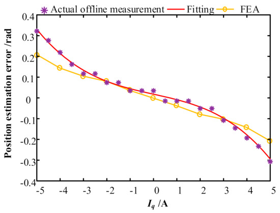
Figure 8.
Offline measured position estimation error.
4. Simulation and Experimental Validation
4.1. Simulation Results
The Matlab/Simulink simulation is developed to verify the time optimized sequence with filterless HF SWVI method. The main parameters of the five-phase IPMSM are shown in Table 1. The magnitude of injected HF square-wave voltage is 60 V for 2 kHz. The PWM switching frequency is 4 KHz, and the sampling frequency is 8 KHz.

Table 1.
Main parameters of IPMSM.
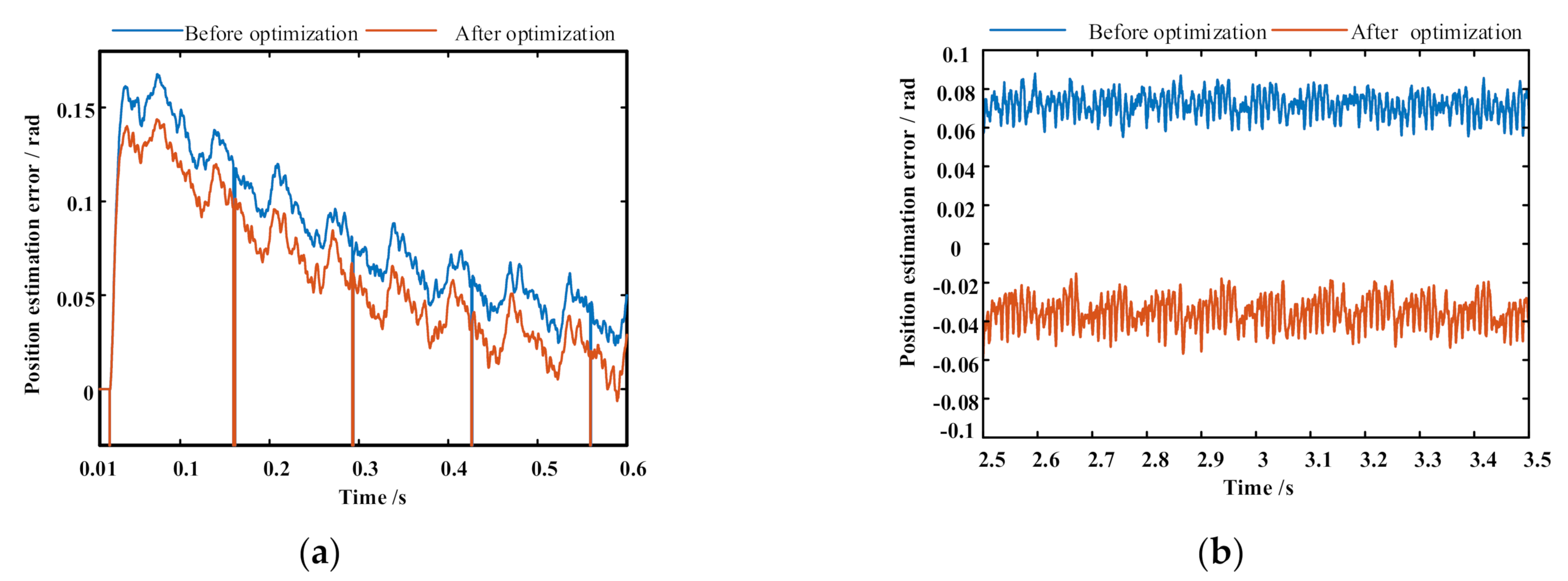
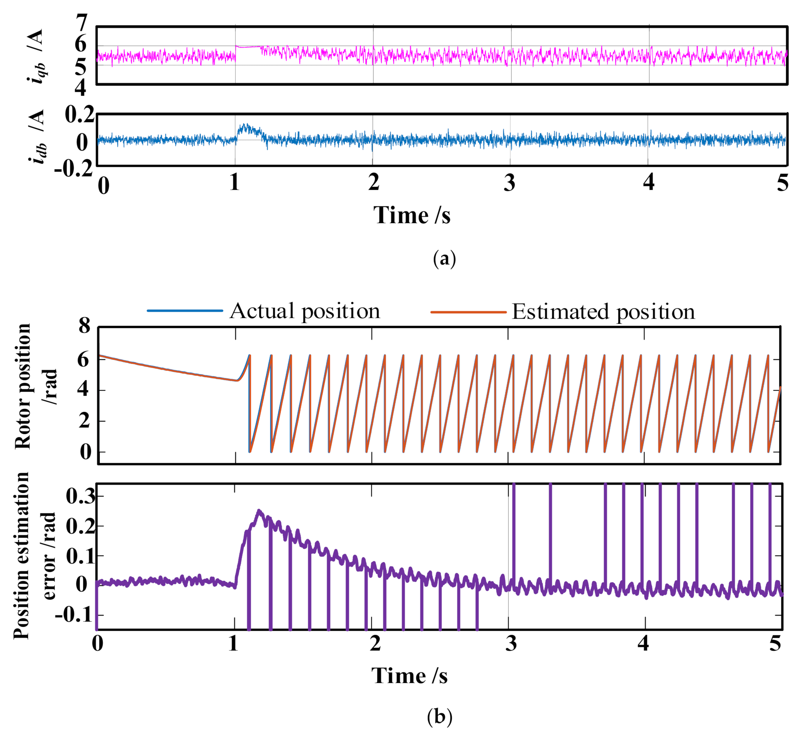
Figure 9 illustrates the effectiveness of the proposed signal processing method without filters. In Figure 9a, the amplitude of the extracted HF current only fluctuates by a few milliamperes in the dynamic process, which means that the proposed method can effectively extract HF currents under dynamic and steady state. In Figure 9b, the comparison of the extracted d-axis FF current with and without the injected HF signals is illustrated. As can be seen, there is a very slight difference between the extracted FF currents under the two conditions, which is caused by the change of zero-crossing time due to the existence of armature winding resistance. It should be noted that the difference can be neglected in dynamic and steady states. Figure 10a shows the comparison results of position estimation error with and without the optimized time sequence. The motor operates with the dynamic step-speed change from 0 to 50 r/min with no load. Compared with the conventional time sequence, the position estimation error is effectively improved with the optimized time sequence. Figure 10b shows the comparison results of steady-state position estimation error, when the motor operates at 300 r/min with no load. It is worth noting that, due to the transition of rotor angle from 2π to 0, there will be a certain spike in the position estimation error. Figure 11 shows the simulation results of the proposed sensorless control with rated load when given speed changes from 0 to 50 rpm at 1.0 s. The maximum position estimation error is 0.26 rad during the start-up region.
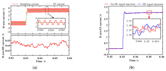
Figure 9.
Current waveforms in the filterless signal processing method with step d-axis current change test: (a) HF current extraction; (b) FF current extraction.
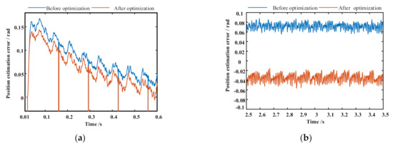
Figure 10.
Comparison of position estimation error before and after optimization: (a) Dynamic state; (b) Steady state.
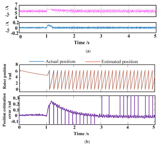
Figure 11.
Simulation results of start-up operation with rated load: (a) FF current; (b) Rotor position and position estimation error.
4.2. Experimental Results
The sensorless control using the time optimized sequence with HF SWVI method is verified at a 2-kW IPMSM test platform as shown in Figure 12. A DSP-TMS320F28335 is adopted as the MCU to execute the sensorless control algorithm. The magnetic powder brake is coaxially fixed with the IPMSM to produce the load torque. An incremental encoder with 4096 pulses per revolution is used to obtain the actual mechanical position and speed of the IPMSM rotor. The PWM switching frequency of the inverter is 4 KHz, and current sampling frequency is 8 KHz. The magnitude of the injected HF voltage is 60 V for 2 KHz. The PI parameters of d- and q-axis in the current loop are selected as Kp,d = 16.2, Ki,d = 77, Kp,q = 18.8, Ki,q = 66. The PI parameters of speed loop are selected as Kp,n = 0.07, Ki,n = 1.2. The PI parameters of PLL are Kp = 115 and Ki = 3306. The DSDU mode is adopted in the DSP.
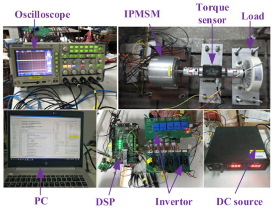
Figure 12.
Experimental platform.
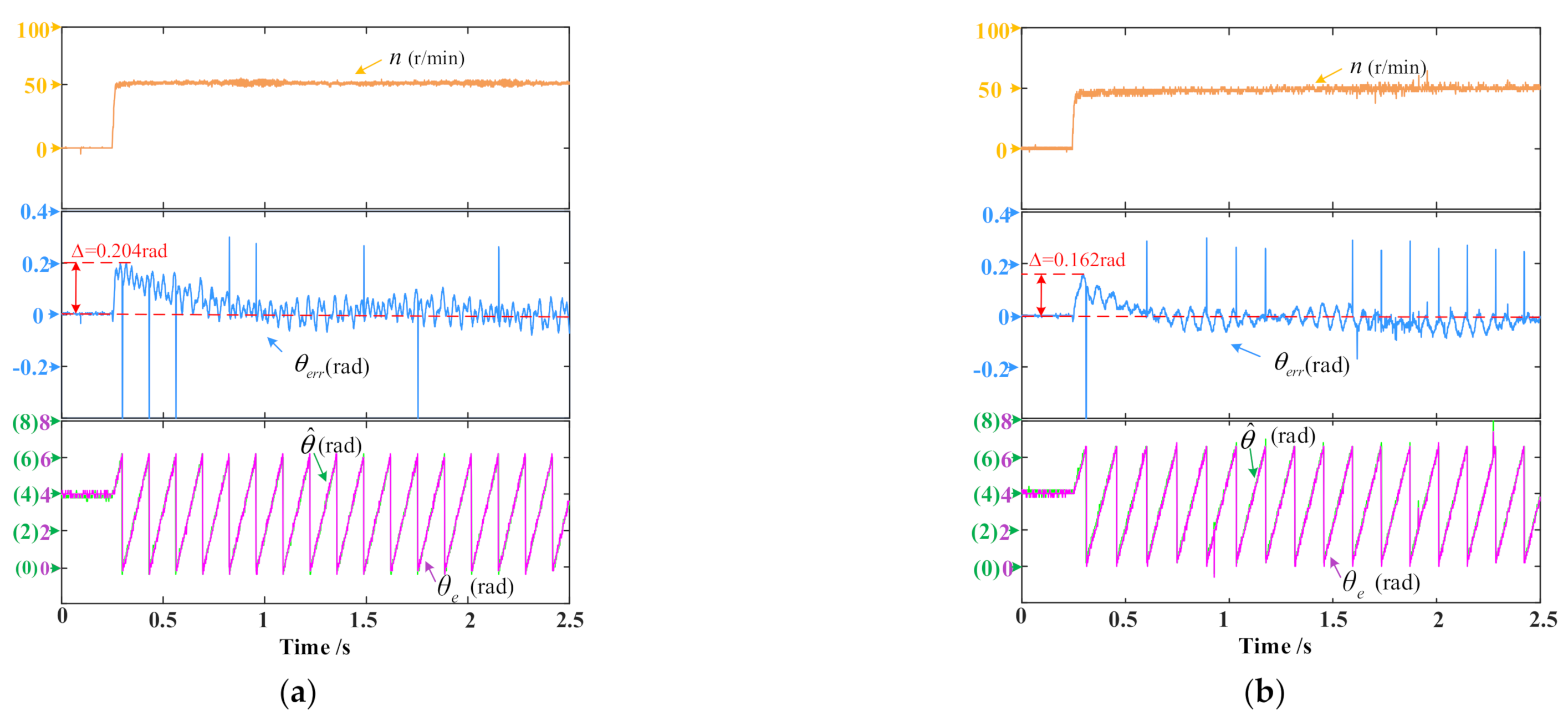
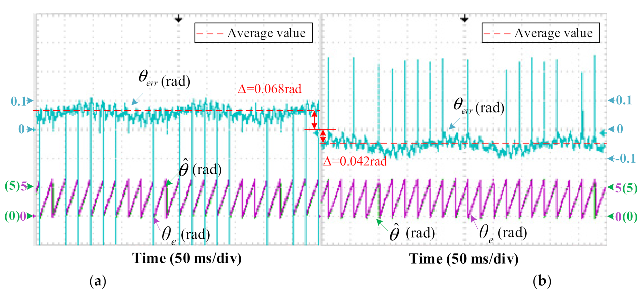
Figure 13 shows this comparison under the dynamic state, when the step reference speed changes from 0 to 50 r/min under no-load condition. As can be seen, after the optimized time sequence is adopted, the maximum position estimation error is decreased from 0.204 rad to 0.162 rad, which means that the steady-state error term in (17) has been eliminated effectively. Figure 14 shows the measured actual speed, position estimation error, estimated angle, and actual angle of sensorless control drive with and without optimization under steady state, when the motor operates at 300 r/min with no load. Among these two curves, before optimization, θerr > 0 indicates that the estimated angle lags behind the actual angle. After optimization, θerr < 0 indicates that the estimated angle is ahead of the actual angle, and its value fluctuates around −0.042 rad, which is in agreement with the calculation result of (20) and Figure 10b. It is noted that the fluctuation of the angular error mainly comes from the nonlinearity of the inverter. Therefore, the proposed optimized time sequence is effective for improving the accuracy of the position estimation.
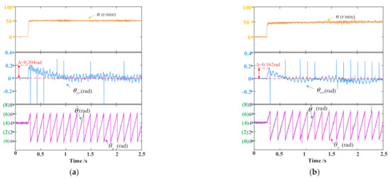
Figure 13.
Comparison of position estimation error under dynamic state: (a) Before optimization; (b) After optimization.
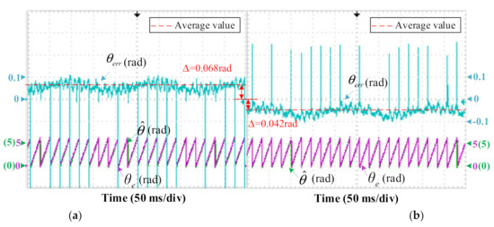
Figure 14.
Comparison of position estimation error under steady state: (a) Before optimization; (b) After optimization.
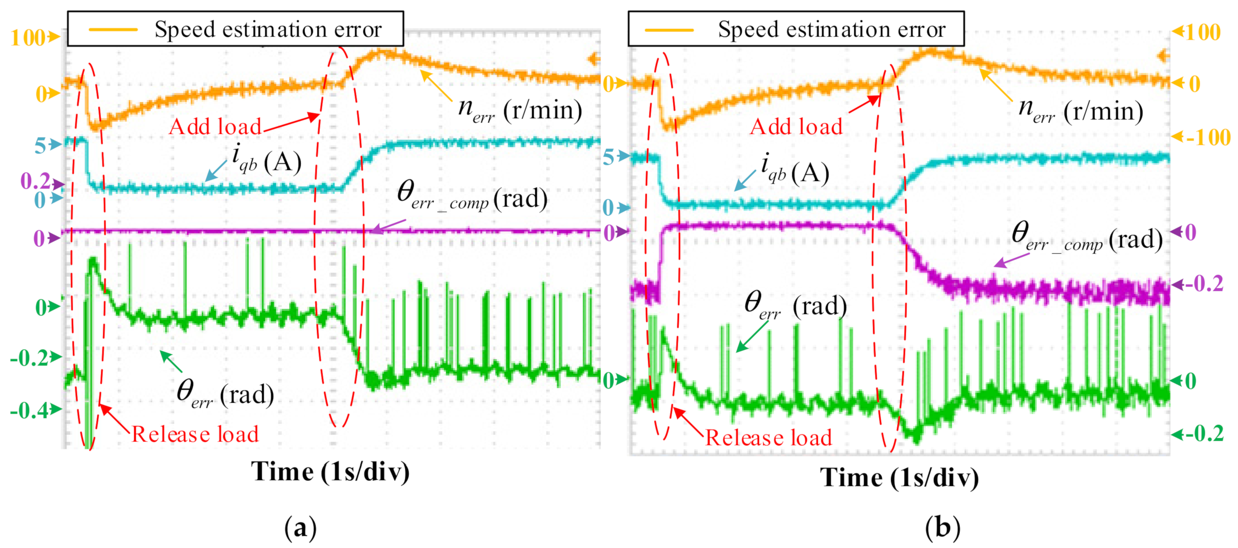
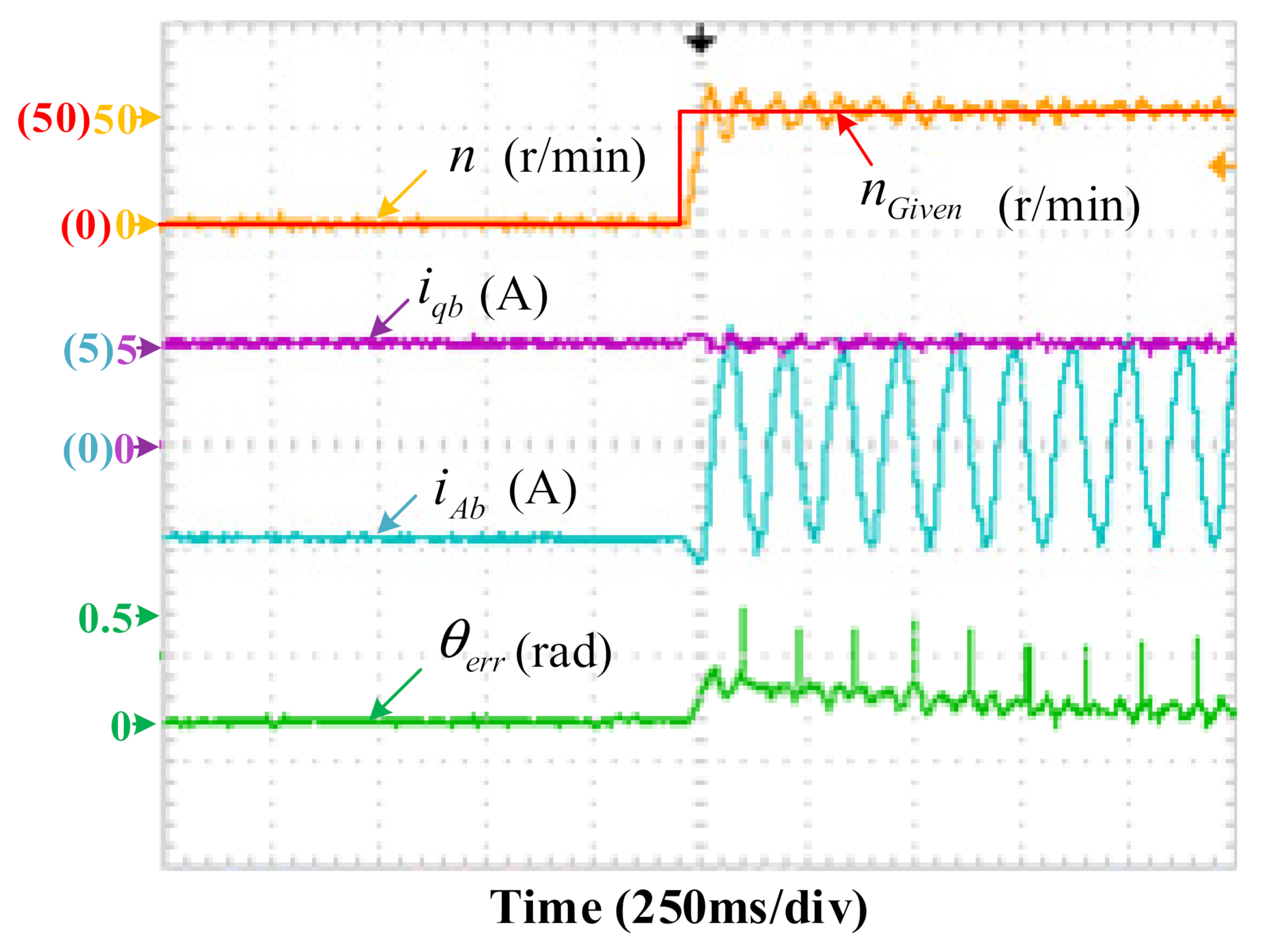
To verify the compensation effect of the online look-up table method on the position estimation error caused by the cross-coupling effect, Figure 14 illustrates the measured speed estimation error, q-axis FF current, angle compensation, and position estimation error of sensorless control drive at 150 rpm with step rated load disturbance. It is noted that in order to suppress the influence of digital control on position estimation error, the proposed optimized time sequence is adopted. By comparing Figure 15a,b, after cross-coupling compensation, the position estimation error in the steady state with load is reduced from −0.3 rad to −0.04 rad. Besides, when the load is released, the fluctuation of the position estimation error is reduced from 0.4 rad to 0.28 rad. In Figure 15b, the amount of angle compensation varies smoothly with the q-axis FF current. Therefore, this experiment can demonstrate that the angle compensation data obtained offline under the static state can effectively correct the estimated angle. Figure 16 shows that the sensorless IPMSM operates from 0 to 50 rpm with rated load, and the maximum position estimation error is 0.23 rad during the start-up region.
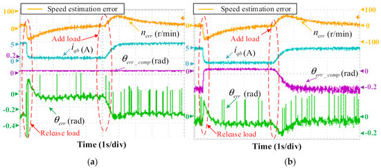
Figure 15.
Position estimation with and without compensation of cross-coupling effects in the dynamic state: (a) Without compensation; (b) With compensation.
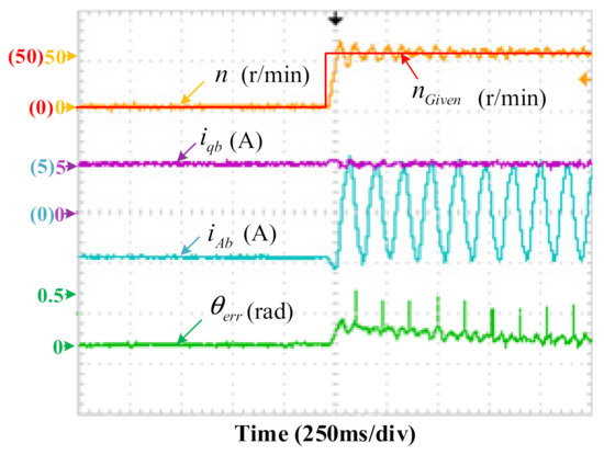
Figure 16.
Experimental results of start-up with rated load. (nGiven is the given speed reference.).
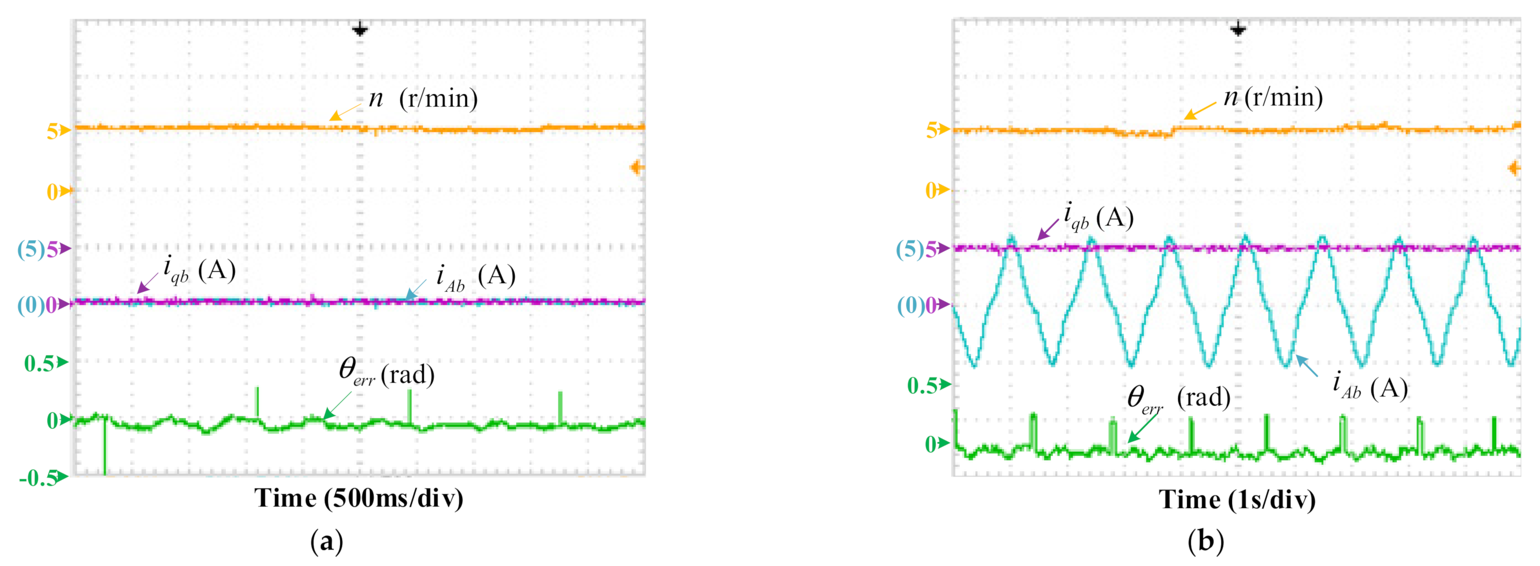
Figure 17 shows the dynamic-state sensorless control performance at ultra-low speed. The motor operates with the speed of 5 r/min (0.33% of the rated speed) with no load in Figure 17a and rated load in Figure 17b. The absolute value of position estimation error at ultra-low speed with full load condition is about 0.08 rad. From the above experimental results, it can be seen that the sensorless IPMSM drive has a satisfying performance adopting the optimized time sequence.
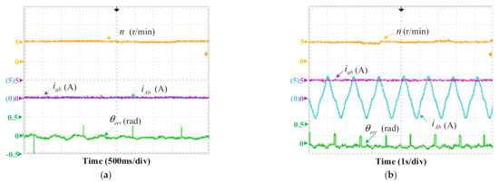
Figure 17.
Sensorless control performance at ultra-low speed: (a) No load; (b) Rated load.
5. Conclusions
The main objective of this paper is to propose an optimized time sequence for a five-phase IPMSM drive based on the HF SWVI method, which can eliminate the additional position estimation error caused by the digital time delay. Besides, by utilizing the optimized time sequence, the accuracy of position estimation is effectively improved in both steady and dynamic state. Meanwhile, to meet the requirement of high dynamic performance for drive system, the signal processing method without using filters is proposed. Moreover, the online position error compensation is adopted for cross-coupling effect via FEA and offline measurements. All theoretical analyses are verified by experimental and simulation results on a 2-kW IPMSM platform in both the steady and dynamic conditions. The proposed sensorless control scheme in this paper is also applicable to three-phase IPMSM drive.
Author Contributions
Conceptualization, L.L. and K.Y.; methodology, L.L. and K.Y.; software, L.L. and K.Y.; formal analysis, K.Y.; investigation, K.Y.; resources, K.Y.; data curation, L.L. and K.Y.; writing—original draft preparation, Z.W. and K.Y.; writing—review and editing, Z.W. and K.Y.; visualization, K.Y. supervision, Z.W.; project administration, Z.W.; funding acquisition, Z.W. All authors have read and agreed to the published version of the manuscript.
Funding
This research was funded by the National Natural Science Foundation of China (NSFC) under Project 62103102, Natural Science Foundation of Jiangsu Province under Project BK202210213, China Postdoctoral Science Foundation under Project 2021M70077, and Fundamental Research Funds for the Central Universities under Project MCCSE2021B04.
Data Availability Statement
The study does not report any data.
Conflicts of Interest
The authors declare no conflict of interest.
References
- Xiong, C.; Xu, H.; Guan, T.; Zhou, P. A Constant Switching Frequency Multiple-vector-based Model Predictive Current Control of Five-phase PMSM with Nonsinusoidal Back EMF. IEEE Trans. Ind. Electron. 2020, 67, 1695–1707. [Google Scholar] [CrossRef]
- Choi, J. Regression Model-Based Flux Observer for IPMSM Sensorless Control with Wide Speed Range. Energies 2021, 14, 6269. [Google Scholar] [CrossRef]
- Wang, S.; Zhao, J.; Yang, K. High Frequency Square-Wave Voltage Injection Scheme-Based Position Sensorless Control of IPMSM in the Low- and Zero- Speed Range. Energies 2019, 12, 4776. [Google Scholar] [CrossRef] [Green Version]
- Zhang, L.; Fan, Y.; Cheng, M. Design and Comparison of Three-phase and Five-phase FTFSCW-IPM Motor Open-end Winding Drive Systems for Electric Vehicles Applications. IEEE Trans. Veh. Technol. 2018, 67, 385–396. [Google Scholar] [CrossRef]
- Lu, K.; Lei, X.; Blaabjerg, F. Artificial Inductance Concept to Compensate Nonlinear Inductance Effects in the Back EMF-Based Sensorless Control Method for PMSM. IEEE Trans. Energy Convers. 2013, 28, 593–600. [Google Scholar] [CrossRef]
- Yu, K.; Fan, Y.; Chen, J.; Wang, Y. Fault-Tolerant Sensorless Control of Position Sensor Failure for Permanent Magnet Vernier Machine. In Proceedings of the 23rd International Conference on Electrical Machines and Systems (ICEMS), Hamamatsu, Japan, 24–27 November 2020; pp. 1251–1256. [Google Scholar]
- Hinkkanen, M.; Leppanen, V.M.; Luomi, J. Flux Observer Enhanced with Low-frequency Signal Injection Allowing Sensorless Zero-frequency Operation of Induction Motors. IEEE Trans. Ind. Appl. 2005, 41, 52–59. [Google Scholar] [CrossRef] [Green Version]
- Basic, D.; Malrait, F.; Rouchon, P. Current Controller for Low-Frequency Signal Injection and Rotor Flux Position Tracking at Low speeds. IEEE Trans. Ind. Electron. 2011, 58, 4010–4022. [Google Scholar] [CrossRef] [Green Version]
- Wang, G.; Xiao, D.; Zhao, N.; Zhang, X.; Wang, W.; Xu, D. Low-Frequency Pulse Voltage Injection Scheme-Based Sensorless Control of IPMSM Drives for Audible Noise Reduction. IEEE Trans. Ind. Electron. 2017, 64, 8415–8426. [Google Scholar] [CrossRef]
- Corley, M.J.; Lorenz, R.D. Rotor Position and Velocity Estimation for A Salient-pole Permanent Magnet Synchronous Machine at Standstill and High Speeds. IEEE Trans. Ind. Appl. 1998, 34, 784–789. [Google Scholar] [CrossRef]
- Kim, S.; Im, J.; Kim, R.A. New Rotor Position Estimation Method of IPMSM using All-Pass-Filter on High Frequency Rotating Voltage Signal Injection. IEEE Trans. Ind. Electron. 2016, 63, 6499–6509. [Google Scholar] [CrossRef]
- Al-nabi, E.; Wu, B.; Zargari, N.R.; Sood, V. Sensorless Control of CSC-Fed IPM Machine for Zero- and Low-Speed Operations Using Pulsating HFI Method. IEEE Trans. Ind. Electron. 2013, 60, 1711–1723. [Google Scholar] [CrossRef]
- Ha, J.I.; Ide, K.; Sawa, T.; Sul, S.K. Sensorless Rotor Position Estimation of An Interior Permanent-magnet Motor from Initial States. IEEE Trans. Ind. Appl. 2003, 39, 761–767. [Google Scholar]
- Wu, C.; Zhao, Y.; Sun, M. Enhancing Low-Speed Sensorless Control of PMSM Using Phase Voltage Measurements and Online Multiple Parameter Identification. IEEE Trans. Power Electron. 2020, 35, 10700–10710. [Google Scholar] [CrossRef]
- Yoon, Y.; Sul, S.; Ide, K. High-Bandwidth Sensorless Algorithm for AC Machines Based on Square-Wave-Type Voltage Injection. IEEE Trans. Ind. Appl. 2009, 47, 1361–1370. [Google Scholar] [CrossRef]
- Hwang, C.; Lee, Y.; Sul, S. Analysis on Position Estimation Error in Position-Sensorless Operation of IPMSM Using Pulsating Square Wave Signal Injection. IEEE Trans. Ind. Appl. 2019, 55, 458–470. [Google Scholar] [CrossRef]
- Kim, S.; Ha, J.; Sul, S. PWM Switching Frequency Signal Injection Sensorless Method in IPMSM. IEEE Trans. Ind. Appl. 2012, 48, 1576–1587. [Google Scholar] [CrossRef]
- Ni, R.; Xu, D.; Zhang, G. Square-Wave Voltage Injection Algorithm for PMSM Position Sensorless Control with High Robustness to Voltage Errors. IEEE Trans. Power Electron. 2017, 32, 5425–5437. [Google Scholar] [CrossRef]
- Zhang, G.; Wang, G.; Xu, D. Saliency-based Position Sensorless Control Methods for PMSM Drives-A review. Chin. J. Electr. Eng. 2017, 3, 14–23. [Google Scholar]
- Jang, J.H.; Sul, S.; Sawamura, M. Sensorless Drive of Surface-mounted Permanent-magnet Motor by High-frequency Signal Injection Based on Magnetic Saliency. IEEE Trans. Ind. Appl. 2003, 39, 1031–1039. [Google Scholar] [CrossRef]
- Li, H.; Zhang, X.; Yang, S.; Liu, S. Unified Graphical Model of High-Frequency Signal Injection Methods for PMSM Sensorless Control. IEEE Trans. Ind. Electron. 2020, 67, 4411–4421. [Google Scholar] [CrossRef]
- Wang, Q.; Zhao, N.; Wang, G.; Zhao, S.; Chen, Z.; Zhang, G.; Xu, D. An Offline Parameter Self-Learning Method Considering Inverter Nonlinearity with Zero-Axis Voltage. IEEE Trans. Power Electron. 2021, 36, 14098–14109. [Google Scholar] [CrossRef]
- Wang, G.; Yang, L.; Xu, D. Pseudo-Random High-Frequency Square-Wave Voltage Injection Based Sensorless Control of IPMSM Drives for Audible Noise Reduction. IEEE Trans. Ind. Electron. 2016, 63, 7423–7433. [Google Scholar] [CrossRef]
- Wu, T.; Luo, D.; Wu, X.; Liu, K.; Huang, S.; Peng, X. Square-wave Voltage Injection Based PMSM Sensorless Control Considering Time Delay at Low Switching Frequency. IEEE Trans. Ind. Electron 2022, 69, 5525–5535. [Google Scholar] [CrossRef]
- Li, Y.; Zhu, Z.Q.; Howe, D.; Stone, D.A. Improved Rotor-Position Estimation by Signal Injection in Brushless AC Motors, Accounting for Cross-Coupling Magnetic Saturation. IEEE Trans. Ind. Appl. 2009, 45, 1843–1850. [Google Scholar] [CrossRef] [Green Version]
- Garcia, P.; Briz, F.; Lorenz, R.D. Saliency-Tracking-Based Sensorless Control of AC Machines Using Structured Neural Networks. IEEE Trans. Ind. Appl. 2007, 43, 77–86. [Google Scholar] [CrossRef]
- Zhu, Z.Q.; Li, Y.; Bingham, M. Compensation for Rotor Position Estimation Error due to Cross-Coupling Magnetic Saturation in Signal Injection Based Sensorless Control of PM Brushless AC Motors. In Proceedings of the International Electric Machines & Drives Conference (IEMDC), Antalya, Turkey, 3–5 May 2007; pp. 208–213. [Google Scholar]
- Lee, Y.; Kwon, Y.; Morimoto, S. Compensation of Position Estimation Error for Precise Position-sensorless Control of IPMSM Based on High-frequency Pulsating Voltage Injection. In Proceedings of the 2017 IEEE Energy Conversion Congress and Exposition (ECCE), Cincinnati, OH, USA, 1–5 October 2017; pp. 859–864. [Google Scholar]
- Guerrero, J.M.; Leetmaa, M.; Lorenz, R.D. Inverter Nonlinearity Effects in High-frequency Signal-injection-based Sensorless Control Methods. IEEE Trans. Ind. Appl. 2005, 41, 618–626. [Google Scholar] [CrossRef]
- Zhang, X.; Zhang, C.; Qiao, M.; Yu, F. Analysis and Experiment of Multi-phase Induction Motor Drives for Electrical Propulsion. In Proceedings of the 2008 International Conference on Electrical Machines and Systems, Wuhan, China, 17–20 October 2008; pp. 1251–1254. [Google Scholar]
- Kim, S.H.; Park, N.C. Simple sensorless algorithm for interior permanent magnet synchronous motors based on high-frequency voltage injection method. IET Electric Power Appl. 2014, 8, 68–75. [Google Scholar]
- Zhang, G.; Wang, G.; Xiao, D. Filterless Square-Wave Injection Based Initial Position Detection for Permanent Magnet Synchronous Machines. Trans. CES 2017, 32, 162–168. [Google Scholar]
- Bae, B.H.; Sul, S. A Compensation Method for Time Delay of Full-digital Synchronous Frame Current Regulator of PWM AC drives. IEEE Trans. Ind. Appl. 2003, 39, 802–810. [Google Scholar] [CrossRef]


Publisher’s Note: MDPI stays neutral with regard to jurisdictional claims in published maps and institutional affiliations. |
© 2022 by the authors. Licensee MDPI, Basel, Switzerland. This article is an open access article distributed under the terms and conditions of the Creative Commons Attribution (CC BY) license (https://creativecommons.org/licenses/by/4.0/).