Article

Single-Phase Charging of EV Embedded Batteries in an MMC with Submodule Override Capability

Department of Electrical and Computer Engineering, University of Canterbury, Christchurch 8041, New Zealand
*
Author to whom correspondence should be addressed.
Energies 2022, 15(6), 2276; https://doi.org/10.3390/en15062276
Submission received: 22 February 2022 / Revised: 15 March 2022 / Accepted: 17 March 2022 / Published: 21 March 2022
(This article belongs to the Section F: Electrical Engineering)

Abstract

:
The modular multilevel converter with embedded batteries is a viable alternative in electric vehicle drive systems. This research investigates integrated charging of the embedded batteries in a three-phase converter from a single-phase source without any additional hardware requirements. Two phases of the converter are connected to the supply while the third converter leg is not connected. In a typical charging of the converter batteries, the batteries with a lower state of charge are prioritised. Then all batteries are balanced at an average global state of charge. This research proposes a new sorting algorithm of the converter batteries with an override capability to bypass any individual submodule if required. This bypassing capability is modulation method independent, thus can be integrated with any modulation method. Simulation results and a real-time emulation of the charging system validate the proposed control method and the override algorithm. In addition, an open-loop switching technique is integrated with a new nearest level control-based measurement method of the battery terminal voltage to estimate its initial state of charge. This measurement facilitates a reduced number of voltage sensors for hardware implementation. This method was simulated and validated by comparing the calculated and the measured values of the battery initial state of charge. Real-time emulation of the system utilising hardware-in-the-loop apparatus was carried out, which confirmed the developed control system functions as expected.

1. Introduction

In electric vehicles (EVs), an onboard battery charger (OBC) is a vital system needed to provide flexible charging options. However, separate OBCs, known as nonintegrated battery chargers, add extra cost to the vehicle and additional weight. Nonintegrated OBCs also often limit charging power to level 1 [1]. Level 1 is the lowest charging level and is limited to a peak of around 3.7 kW, via a standard 16 A rated cable [2]. Battery chargers rated at power level 2 have nominal power ranges from 6.6 to 7.4 kW, via a standard 32 A rated cable [1]. Power level 3 is provided through dedicated commercial chargers that have a power rating more than 7.4 kW. There are also different types of nonintegrated OBC, categorised by charging levels and the utilised components as reviewed in [2]. Nonintegrated OBC components typically include a filter, power factor correction stage, and an isolated DC-DC converter.
To reduce costs, hardware complexity, and weight, and enable higher onboard charging power levels, it is possible to utilise existing EV converter hardware and the driving motor with minimal additional components as an integrated OBC [2]. Integrated OBCs have different configurations according to the utilised traction components. Integrated OBCs can employ the motor and the traction converter with modification of the motor construction and connection as discussed in [3]. In some configurations, the motor and converter construction can be unchanged but an interface is added for grid connection. Proposed work in [4] utilised the three-phase motor and the inverter as an onboard charger. Additionally, an EMI filter and buck-type full bridge converter are used.
While charging from a three-phase source is important for fast and commercial applications, charging from a single-phase source is vital for domestic charging. Thus, utilising a three-phase converter as a single-phase charger has been investigated by other research groups [5,6,7]. Moreover, a single-phase charger was investigated for connection of a multiphase machine in [8]. The topology proposed in [5] utilised a standard two level three-phase converter to charge the EV battery from a single-phase supply. Another approach is proposed in [6], which discusses utilising an auxiliary circuit and the motor to charge the battery from a single-phase source.
Recently, modular multilevel converters (MMCs) have been investigated for traction applications in EVs [9,10,11,12,13,14,15,16]. An MMC is comprised of a large number of connected identical submodules, usually consisting of a low-voltage rated half-bridge per module. The resultant output voltage is a multilevel waveform with negligible harmonic content and is completely scalable, permitting high voltage levels to be effectively reached. Compared to conventional multilevel converter topologies, the modular nature of an MMC can offer active voltage balancing, dynamic energy management, module redundancy, control flexibility, and fault-tolerant capabilities, making it a popular choice for medium and high-power applications [17,18].
The approach of the study detailed here is to utilise a three-phase modular multilevel converter (MMC) with embedded batteries (EB) in an EV power train as a single-phase integrated OBC. The converter also has the capability to override any individual converter submodule, which increases the converter availability and reliability. The research details the available literature background of the MMC-EB as a motor drive with a focus on its charging arrangement in Section 2. Section 3 details the developed converter control approach and the SM override method. A new open loop switching method to minimise the hardware requirements of the converter implementation and the simulation of the converter operation are provided in Section 4. A validation of the converter control system using dSPACE/MicroLabBox is presented in Section 5, followed by a discussion in Section 6.

2. MMC-EB as Onboard Battery Charger

A three-phase MMC based EV drive system was proposed in [14] by replacing the conventional submodule (SM) capacitor with an embedded battery (EB), as shown in the sub-module insert in Figure 1. Each phase leg has an upper and a lower arm with the same number of SMs (N). The converter is fully scalable, modular, and can be controlled to operate in the four quadrants of operation modes. The MMC-EB is utilised to drive an EV three-phase traction motor in [9,12,13,19]. Due to the bi-directional power flow capability, charging from a three-phase source is a possible charging option of the MMC-EB, similar to a regenerative braking mode operation in an EV. An MMC-EB is investigated as an integrated three-phase EV battery charger in [12]. A traditional three-phase MMC is studied as a non-integrated battery charger in [20]. However, the connection of the three-phase MMC-EB to a single-phase grid to charge the embedded batteries requires a modified control algorithm and alteration of the converter hardware. The authors from [21] proposed a charging method for an MMC-EB from a single-phase supply with the same hardware configuration as the three-phase converter. In that method, two legs are connected to the single-phase supply and have a two-leg state of charge (SOC) controller. A third leg SOC controller also controls the third, disconnected leg, average SOC. In addition, balancing of the SOC of the individual batteries in [21] is based on PI controllers which increases the system complexity. For the single-phase charger detailed in this paper, in the developed control system, the converter’s unconnected leg has no dedicated average SOC controller. Instead, the third leg voltage is set to be the nominal DC bus voltage. Moreover, there is no arm control in the third leg, but an individual SOC controller as detailed in the converter control section. Gao et al. [18] provided a redistributed PWM modulation technique of an MMC-EB connected to AC grid during submodule faults. The fault override method is based on the redistribution of the PWM waveform and the method mainly suits PWM modulated inverters. For the override method presented in Section 3 of this paper, the override occurs during the sorting stage, giving this method flexibility to be employed with different modulation schemes.

MMC-EB Basic Operation

The terminal voltage of any phase x ( v x ) in an MMC-EB converter is formed by the switching of the SMs in the upper and the lower arm of this phase (leg). The SMs are switched in a complementary method, so that the number of total active SMs in this leg equals N. Thus, the voltage between the positive and the negative terminals of the converter legs is essentially the same, considering that each SM battery has the same rated voltage ( V c ) [22]. Each arm has N SMs and an inductor (L). The voltage in the upper and the lower arm ( v u , x and v l , x ) of phase x can be written in terms of the arm currents ( i u , x and i l , x ) as [12]:
v u , x = N V c 2 v x L d i u , x d t   [ V ]
v l , x = N V c 2 + v x L d i l , x d t   [ V ]
The converter arm currents can be expressed as:
i u , x = i c i r , x + i x 2 i l , x = i c i r , x i x 2 i c i r , x = i u , x + i l , x 2   }   [ A ]
where i c i r , x is the circulating current and i x is the phase current.
The circulating current flows from one arm to the other due to their instantaneous voltage difference. Moreover, a DC component of the circulating current flows from the legs with higher instantaneous voltage to the legs with lower voltage. By neglecting the voltage drop due to the arm inductor, the leg voltage can be written as:
V d c = v u , x + v l , x N V c   [ V ]
Arm circulating currents can be minimised by maintaining the instantaneous power difference between arms at zero. The power difference p x , d i f f ( p u , x p l , x ) in phase x can be expressed as:
p x , d i f f = v u , x i u , x v l , x i l , x = 2 v   x i c i r , x + V d c 2 i x   [ W ]
Similarly, the leg power ( p x ) can be written as:
p x = V d c i c i r , x v x i x   [ W ]
As observed from Equation (6), the leg power is a function of the phase voltage and current, in addition to a DC power component that can be exchanged between legs. An appropriate SOC controller can be utilised to equalise the average SOC ( S O C x ¯ ) of the converter legs [23]. The average SOC in a converter leg can be calculated from the equation:
S O C x ¯ = 1 2 N i = 1 2 N S O C i , u , x + S O C i , l , x
The upper and lower arm average SOC ( S O C u , x ¯ , S O C l , x ¯ ) in an MMC leg can be determined using:
S O C u , x ¯ = 1 N i = 1 N S O C i , u , x S O C l , x ¯ = 1 N i = N + 1 2 N S O C i , l , x }
where the total converter EB average SOC is:
S O C ¯ t = S O C ¯ a + S O C ¯ b + S O C ¯ c 3

3. MMC-EB Single-Phase Charger with SM Override Capability

The MMC-EB single-phase charger developed by the authors is shown in Figure 2. Although charging the EB is the main control objective, reliable operation of the converter requires additional control objectives to be considered. These operational control objectives can be summarised as:
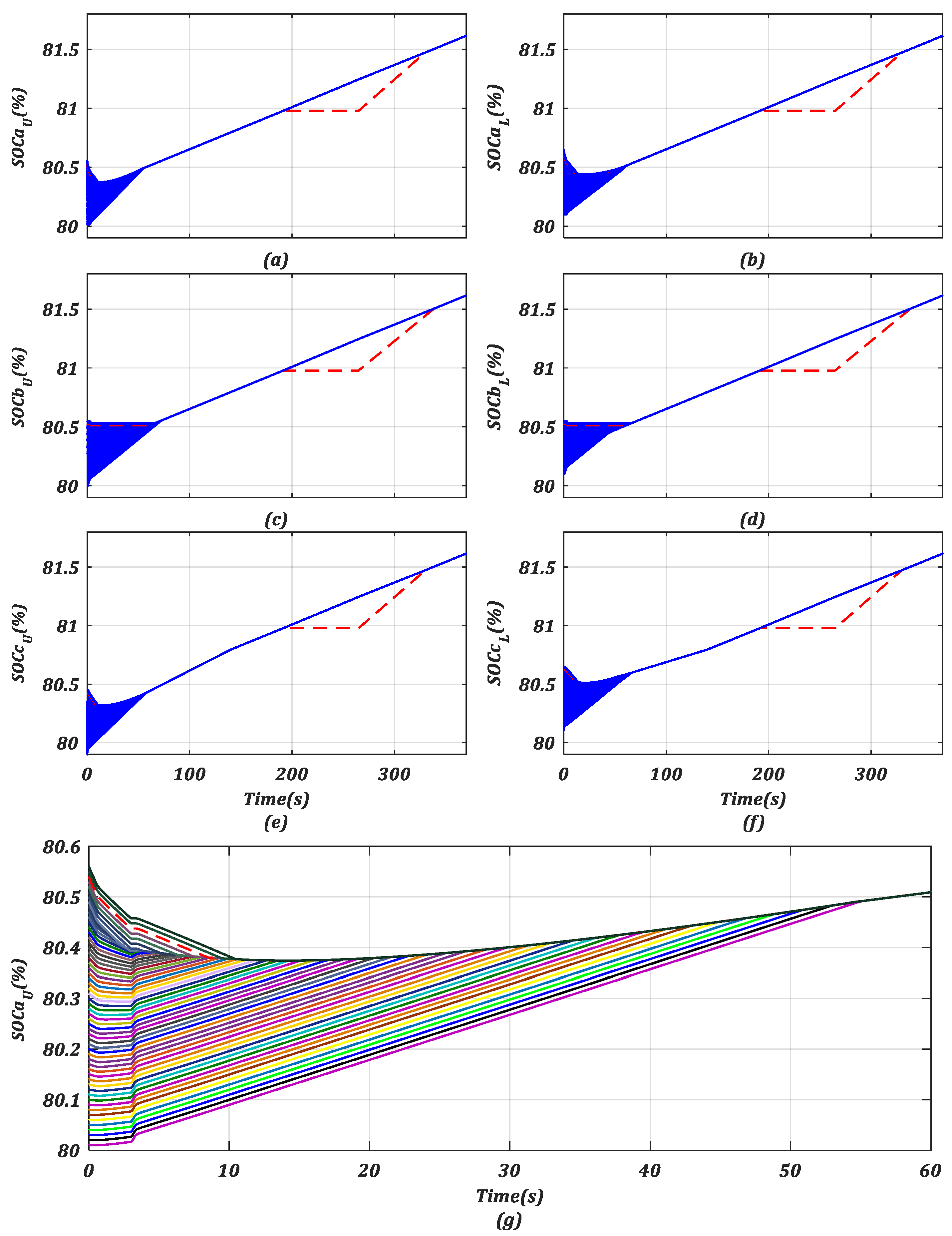
  • SOC of the converter SM batteries managed to be closely balanced (battery management operation);
  • Capability of the converter control to override any individual SM while the rest of the converter SM batteries continue to be charged;
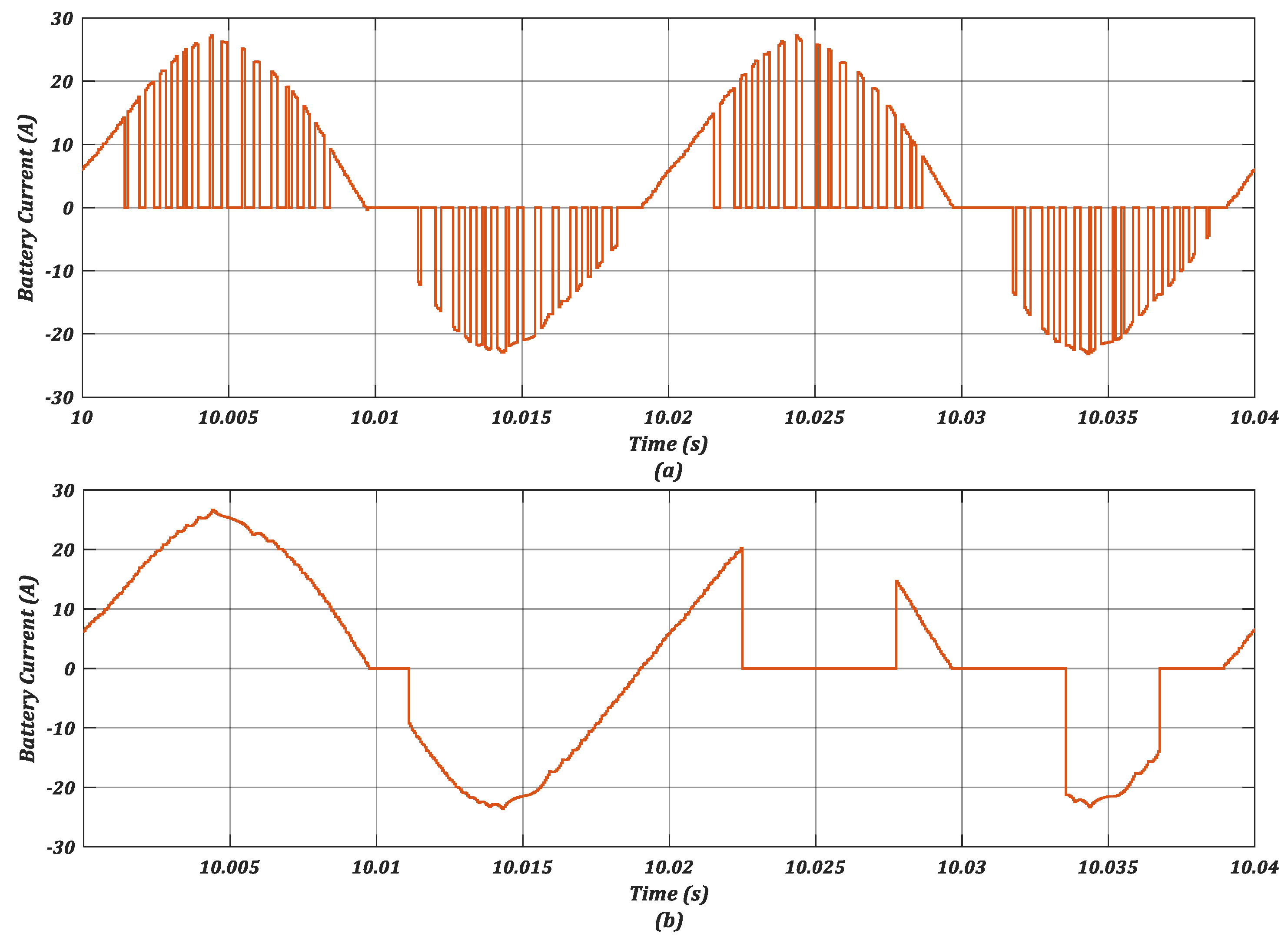
  • Minimising circulating currents in converter legs to decrease the RMS value of the arm currents, consequently decreasing the converter losses [24].
Based on these requirements, three subcontrollers are utilised to equalise SOC and minimise circulating currents.

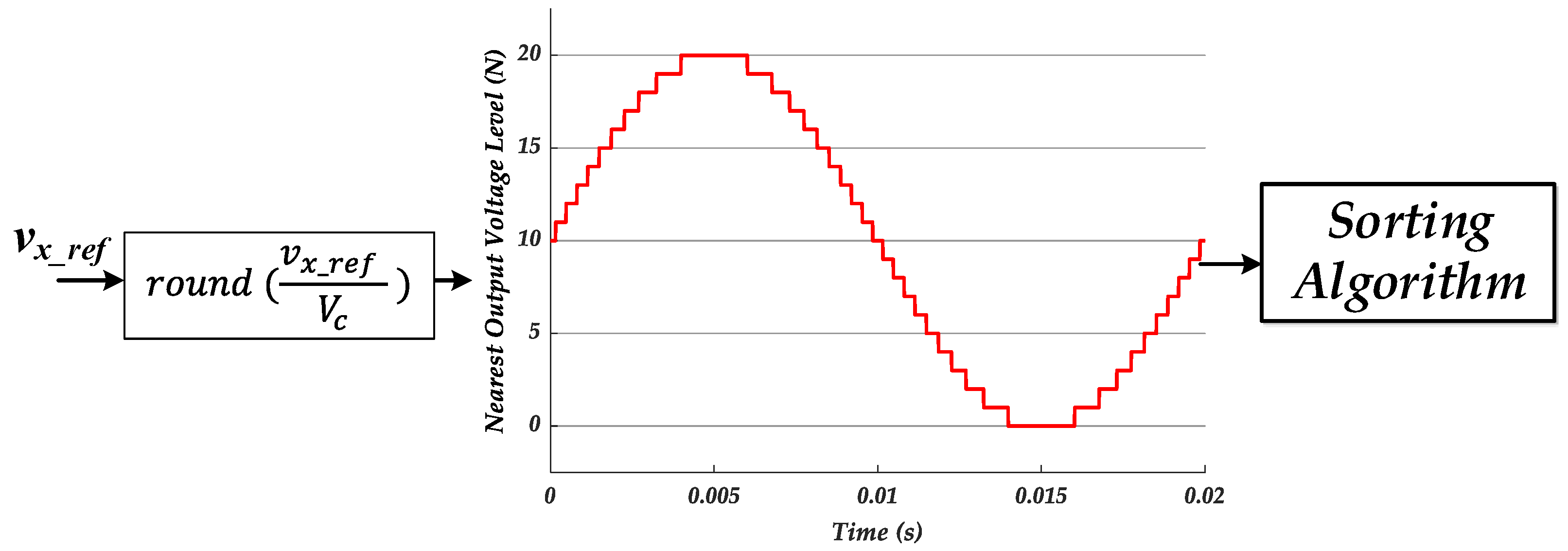
3.1. SM SOC Controller with EB Override

Various pulse width modulation (PWM) schemes can be implemented to generate driving signals for MMC SM switches [25]. The nearest level controller (NLC) method is utilised here due to the expected high number of voltage levels in this specific MMC-EB application. Thus, an accurate approximation of the reference voltage can be realised. Moreover, batteries have a slow voltage variation for a given amount of charge transfer compared to capacitors, and therefore lower switching frequencies can be employed. A round function is used to return the input voltage to the nearest whole output level as:
N * = r o u n d ( v x V c )
where N * is the number of required levels during sampling time ( T s ) and ranges from 0 to N. Based on N * , the sorting algorithm inserts the same number of SMs to generate the required output voltage. The sorting block assigns an index to each SM, then arranges the SMs according to their SOC in an ascending order. SMs are inserted or bypassed according to their SOC and arm current direction as follows:
  • If i a r m is positive, then any SM with an index located in the range of 1 S M i n d e x N * is inserted to form the arm voltage waveform ( S a 1 = off and S x 1 = on). The inserted SM will then charge during that sampling period; indexes in the range of N N * + 1 S M i n d e x N are bypassed ( S a 1 = on and S x 1 = off);
  • If i a r m is negative, then any SM that is located between N N * + 1 S M i n d e x N is inserted ( S a 1 = off and S x 1 = on). In this case the inserted SM will discharge.
Accordingly, the NLC and sorting algorithm can be characterised as a combined modulator as shown in Figure 3.

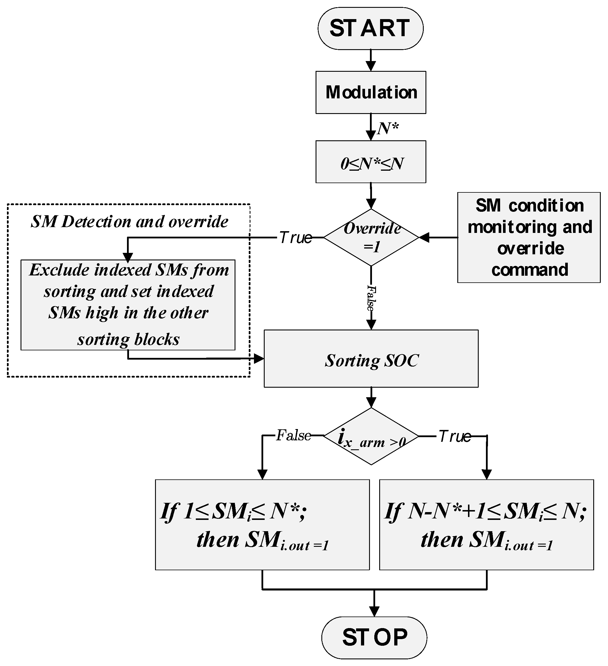
3.2. SM Override Capability of the MMC-EB

The developed override method initially considers an undesirable increase in the temperature of an EB, where an elevated battery temperature over time can degrade the battery and reduce its functional lifetime [26]. The sorting algorithm can be also utilised to isolate a SM-EB that undergoes an unacceptable SOC deviation. Furthermore, this sorting method can be extended to bypass a SM for any other definable fault. Utilising this sorting block to override a SM gives a degree of decoupling and can be implemented with any type of MMC PWM method.
In EV applications, and during single-phase charging of a three-phase MMC-EB, the available number of batteries, N, is higher than the required batteries, N * . Therefore, a redundant number of SMs equal to N N m a x * can be used to bypass some SMs if necessary. As illustrated in Figure 4, an override subroutine is included in the sorting algorithm. The sorting algorithm limits the number of switched SMs to be within range 0 N * N . Thus, if N* has a value higher than the number of SMs (N) in an arm, N* will be saturated to N. If an arm has a negative N*, it will be limited to zero. The main principle of the override mechanism is to bypass a specific SM and select the next indexed SM. Consideration during this subroutine is given to the current direction. There are six separate NLCs and sorting blocks, supervised by a higher-level control block to assign an override command to the designated SMs. Battery SOC equalisation (the battery management operation) is applied during both normal and override modes, except for the bypassed SMs.

3.3. Sorting Optimisation

The sorting algorithm is executed once per sampling period. During each sampling period, the SOC of all batteries is updated, then a sorting action is required. Thus, switching is not only dependent on the NL waveform, but also depends on the SOC sampling. A typical SM battery current is shown in Figure 5a during normal sampling of the SOC. In order to reduce the rate at which any SM battery current is switched, the method employed here samples the battery SOC only when the battery current direction changes. Therefore, any individual SM will be switched only once during a half cycle, as shown in Figure 5b. A hysteresis band also can be added during the transition from one level to another to avoid any arbitrary switching when the reference voltage is highly distorted. From the observation of the NLC behaviour in this study, the hysteresis band is not required.

3.4. Converter Leg Controller

As shown in Figure 2, the SOC for converter legs A and C are controlled via circulating current components (DC and AC). Each leg average SOC ( S O C x ¯ ) is compared to the total average SOC of the converter. Then, a PI controller (PI2) calculates the required reference DC current to be exchanged with converter legs to equalise S O C x ¯ . A low pass filter separates the actual DC circulating current component to compare it with the reference current component. The inner PI controller (PI3) generates a leg balancing voltage v l e g * . The converter’s unconnected leg is controlled to produce a constant DC voltage, the converter nominal DC voltage, to emulate a single-phase full bridge operation of an MMC-EB. This is achieved by setting the reference voltage to the nominal DC voltage of the converter ( N V c 2 ):
v u , b = N V c 2   &   v l , b = N V c 2   [ V ]
In this operating mode, the circulating current in phase B has only a DC component, and the AC circulating current equals zero.
The control gains of the leg balancing controller can be determined by characterising the battery charging (the integral of the charging current, moderated by battery capacity (Q), giving SOC) and the linearised relationship between SOC and battery voltage (K), as shown in Figure 6. As this involves an integral action, actually only proportional control is required. However, PI controller gains were chosen to implement the phase lead at around 0.17 rad/s, and a control bandwidth of 0.48 rad/s, with a phase margin of approximately 71.5 degrees. These gains are Kp = 124.5 and Ki = 19.1. The control bandwidth is deliberately low, as it averages the effect of the actuator over several electrical cycles.

3.5. Arm Controller

In the arm controller, the upper and lower arms SOC is compared, then a controller (PI1) generates the reference arm voltage v a r m , x * . The output of the arm controller is used as a weighting factor to scale the reference voltage, v u , m * and v l , m * , as follows:
v u , m * = ( 1 + v a r m , x * ) v u , x *   [ V ]
v l , m * = ( 1 v a r m , x * ) v l , x *   [ V ]
Arm reference voltages can be derived from the phase reference voltage as:
v u , x = 1 v x 2   and   v l , x = 1 + v x 2
The phase voltage of the MMC-EB can be expressed in terms of the submodule voltage and modulation signal as:
V x = m a * N V c 2 s i n ( ω t + θ x )   [ V ]

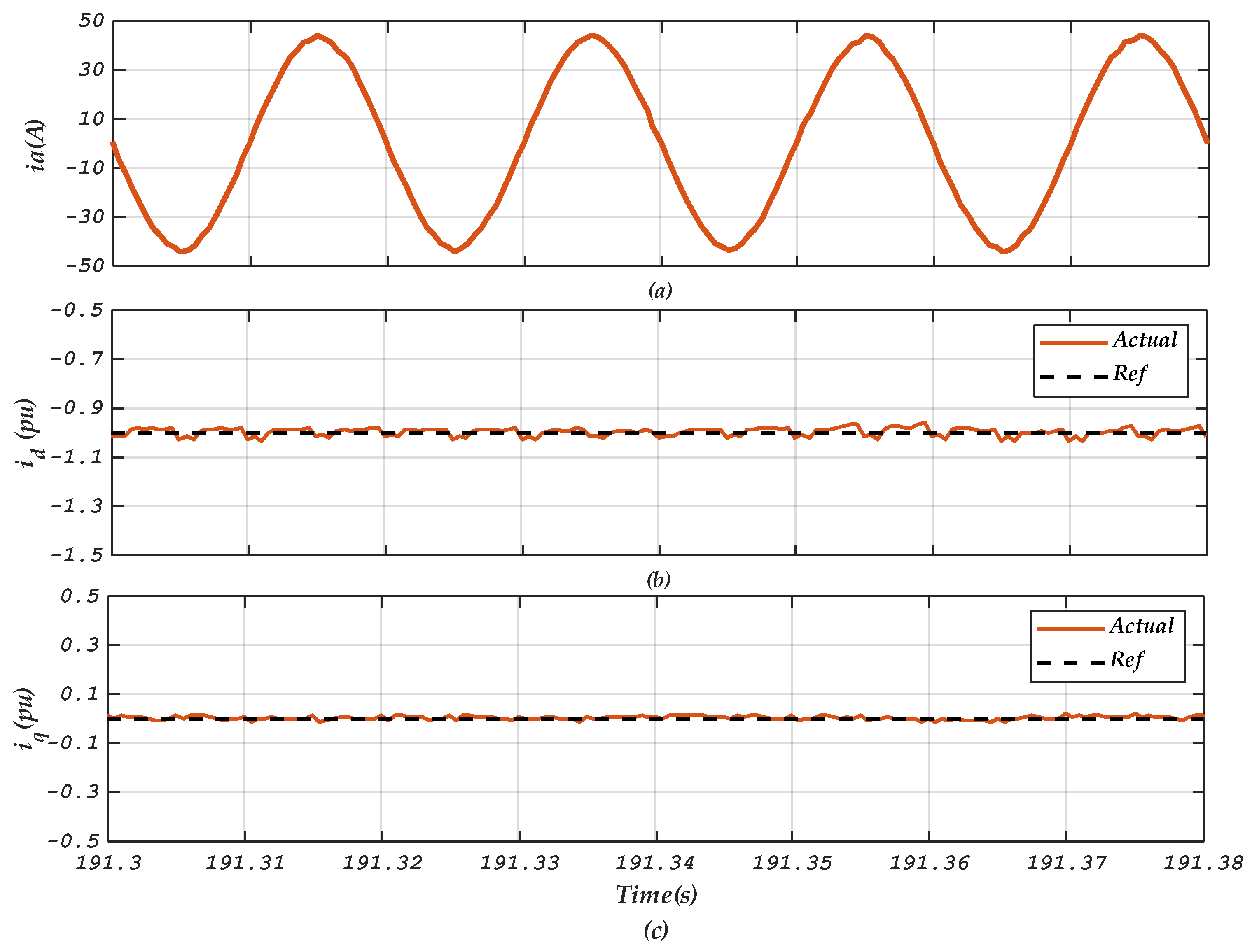
3.6. Voltage Oriented Control

The main objective of the control system is to enable charging operation of the three-phase converter from a single-phase supply. Voltage oriented control is implemented as shown in Figure 2. The control system is based on current control loops. For unity power factor operation, i q l * is set to zero. The converter is connected to a single-phase grid; thus, to control the converter in dq coordinates, a delay of ¼ cycle is used to calculate the stationary voltage α of the converter reference voltage [27]. A phase locked loop (PLL) is used to determine the grid angular frequency.

4. Simulation of MMC-EB Charging When Connected to a Single-Phase Grid

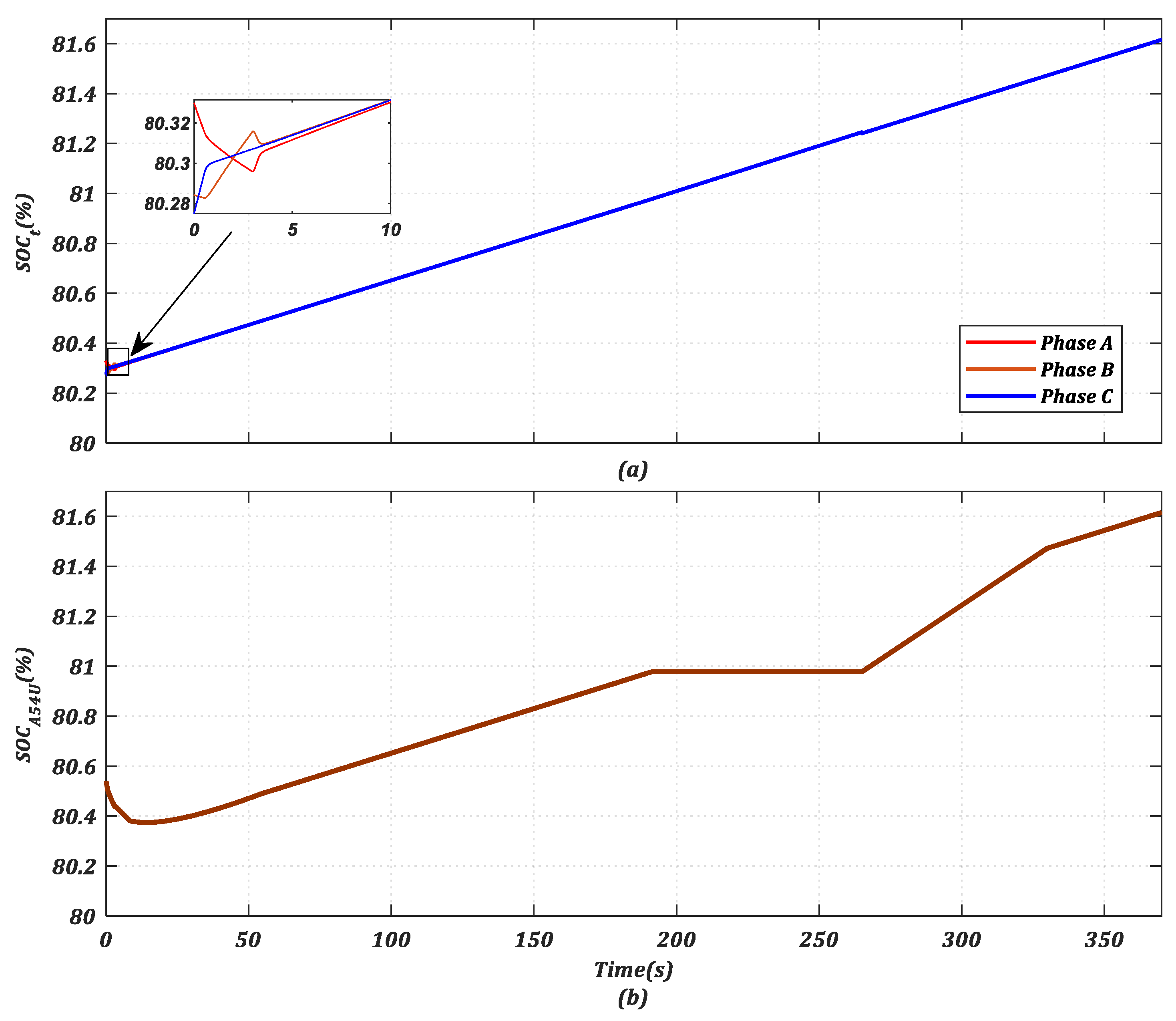
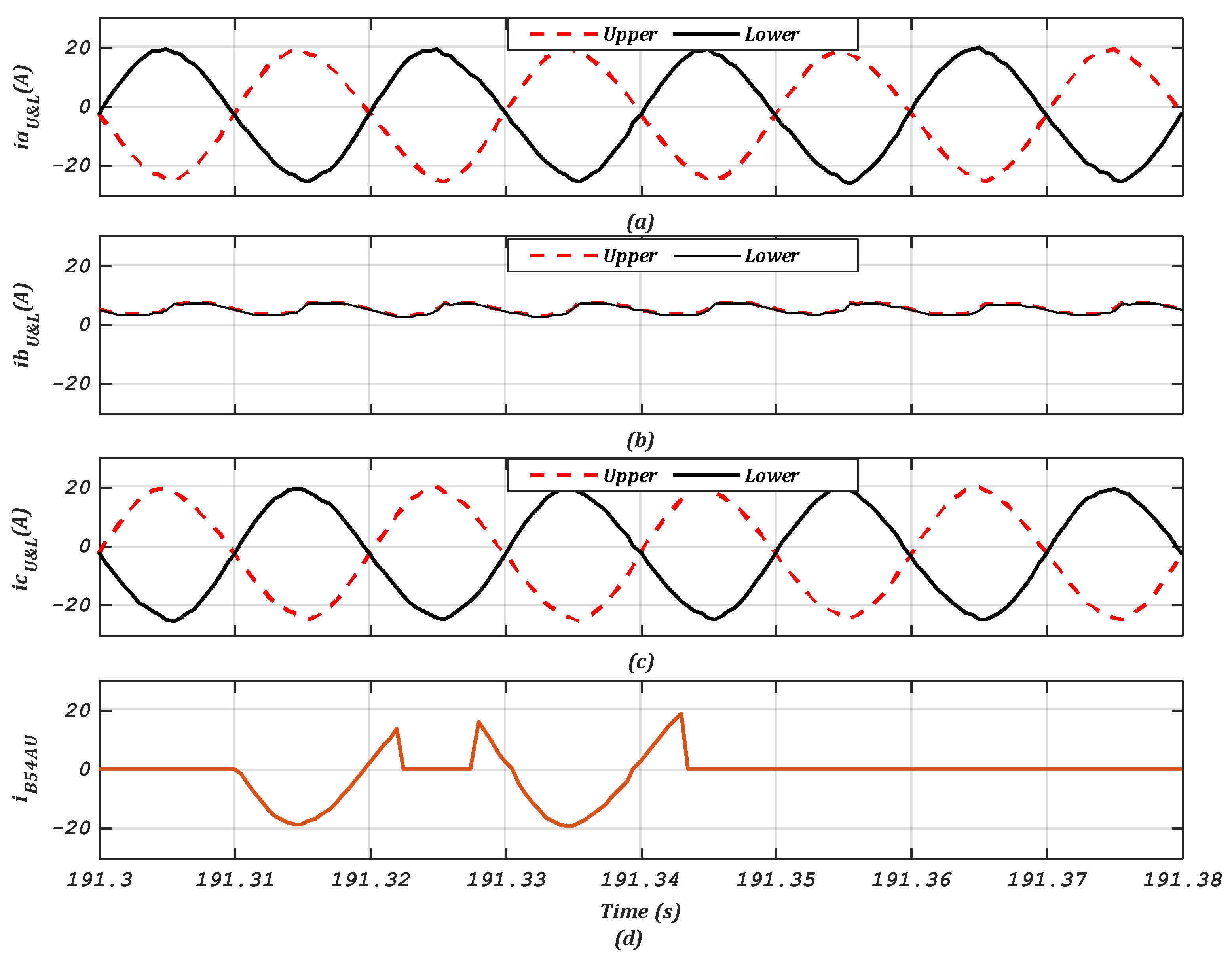
4.1. Case Study of One SM Bypassed in Each Arm Due to an Elevated Embedded Battery Temperature

In the following case, a three-phase MMC-EB is connected to a single-phase grid. Simulation parameters are shown in Table 1, and the sampling time ( T s ) is 50 µs. To emulate the expected normal narrow SOC operational range and decrease initial equalisation time, initial EB SOC values are distributed randomly from 79.90% to 80.65% in the converter arms, as shown in Figure 7. Each SM-EB has two identical series cells with a rated voltage of 3.6 V each. It is assumed that both cells have the same SOC and no internal cell balancing is required per SM. In a commercial application of the MMC-EB, each SM could have a single cell to eliminate any additional SOC balancing elements. Battery SOC is equalised for all SMs within 75 s from the start of the simulation according to the implemented control arrangement.
The SM override subroutine is activated to bypass any SM with a battery that has a threshold higher temperature compared to the converter battery’s average temperature (determined as being an undesirable condition). In this case study, the override activation temperature difference (TD) is set to +0.5 °C. The bypassed SM will only be reinserted when the difference drops again to +0.1 °C. Figure 8 shows the isolation of the SM 54 battery in the phase A upper arm when the TD equals +0.5 °C. SM 54 normal operation is restored at TD equals +0.1 °C. The SOC for the upper and lower arms in each phase are shown in Figure 9. There are no arm controllers in phase B, but the average SOC in the upper and lower arms of phase B is equalised due to a modified individual SOC algorithm in phase B, as shown in Figure 9b. This modified algorithm uses the average SOC of the converter leg B as a global reference for all SMs in phase B. The average SOC of the converter phases (or legs) is also equalised, as shown in Figure 10a.
Of note here is that during the SM override period, the average SOC values in the converter arms and legs are unchanged. This is achieved by isolating the same number of the bypassed SMs in each converter arm. Upper and lower arm currents in phase A, B, and C are shown in Figure 11a–c respectively. Figure 11d shows the bypassed battery current before and after isolation. Phase A current is shown in Figure 12a. The current active and reactive current components are shown in Figure 12b,c respectively.

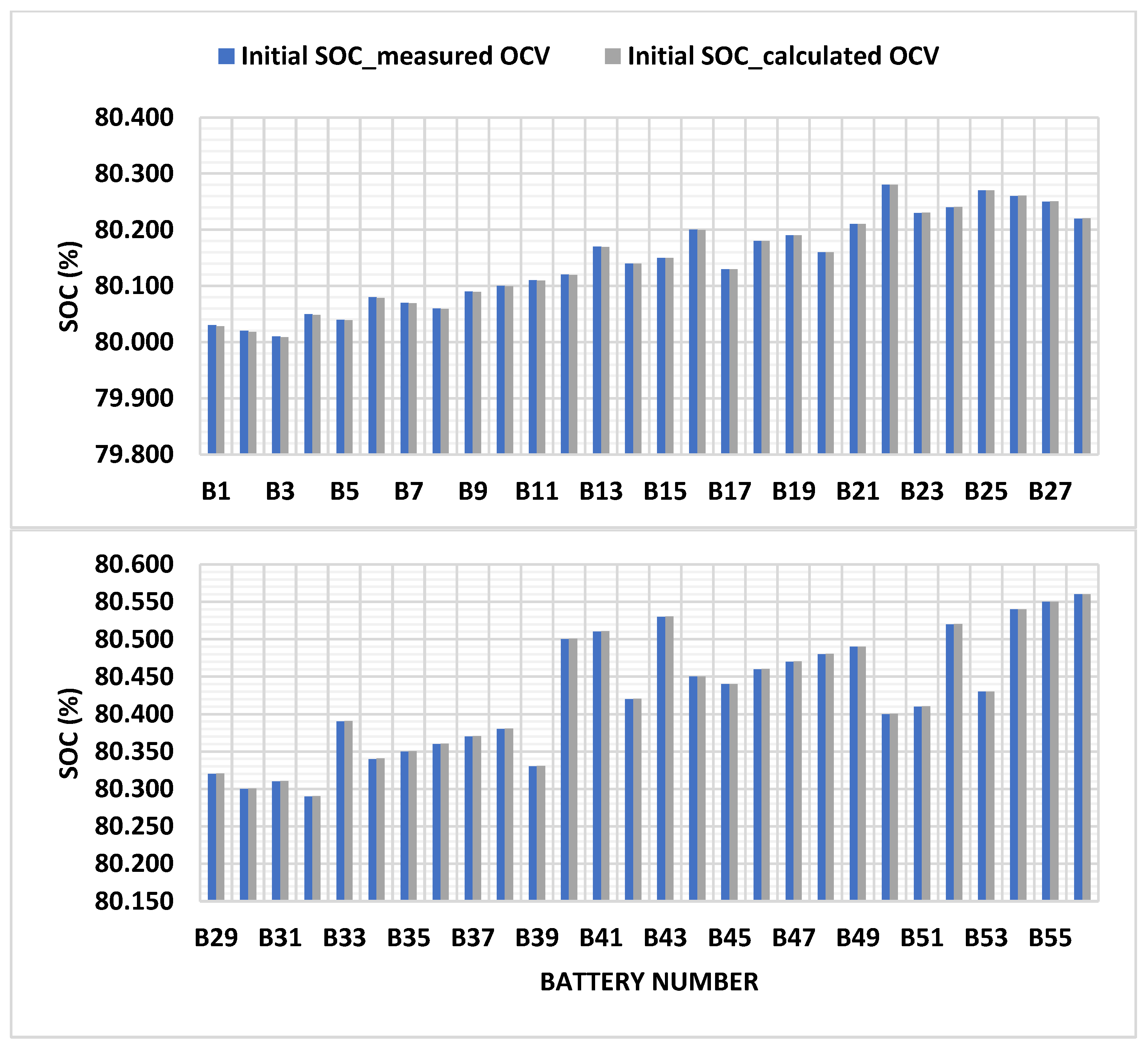
4.2. Measurement of OCV and Estimation of Initial SOC of EBs

During hardware implementation of an MMC-EB, the open-circuit voltage (OCV) of a SM battery is required in order to estimate its SOC using the Coulomb counting method. The OCV also can be utilised with different SOC estimation methods [28]. When implemented in an EV, the MMC-EB is comprised of a high number of SMs. Offline measurement of individual SM battery voltage using voltage sensors adds an extra cost to the converter implementation. This research shows that an effective calculation-based method can reduce the required number of voltage sensors to only six, i.e., one per arm.
The OCV calculation technique here utilises the NLC switched arm voltage waveform. If a specific SM battery switching instant is known, the corresponding decrease in the instantaneous arm voltage is the switched battery terminal voltage of that SM, as shown in Figure 13b. For a no-load condition and assuming standard circulating current, the battery open-circuit voltage is the SM terminal voltage. The arm voltage decrease step is utilised instead of voltage increase to avoid calculation cumulative error. The instantaneous upper arm voltage in phase x can be expressed as:
v u , x = i = 1 N s w V c i , u , x   [ V ]
where N s w is the number of inserted SMs. Under the assumption that the SOC values of the submodule batteries are not known, an open loop switching algorithm can be applied instead of the sorting algorithm detailed in Section 3.
The open loop switching algorithm principle is to switch each SM for a constant switching period. This period can be identified and triggered by switching levels (N) in Equation (10). When N * increases by an integer step, a SM will be switched on. During switching on, all SMs are sorted in an ascending order from top to bottom. The SM that has an order number that is equal to the N * value will be switched on. To switch off a SM, SMs are sorted in a descending order from top to bottom. This means the earlier a SM is switched on, the greater its priority to be switched off. As a result, not only is the level number the main trigger to switch on or off a SM, but also the direction of the voltage reference. In the NLC modulated waveform, the same number of active levels is repeated twice during any reference voltage full cycle, as shown in Figure 13. As an example, level number 26 is repeated twice during a full voltage cycle. Thus, the developed switching algorithm requires another identifier to determine which sorting order is to be selected. The second identifier is the rate of change in the reference voltage, as shown in Figure 13c. When the switching levels are increasing, the rate of change flag (R) has a positive value, otherwise R equals zero. According to R values during a reference voltage cycle, there are four switching regions, as shown in Figure 13a. The switching regions are divided as follows:
  • Region 1: Voltage reference is positive and R equals 1;
  • Region 2: Voltage reference is positive and R equals 0;
  • Region 3: Voltage reference is negative and R equals 0;
  • Region 4: Voltage reference is negative and R equals 1.
Each SM can be switched on during Region 4 or Region 1, and switched off during Region 2 or Region 3, respectively.
The arm current is dependent on the phase current and the arm circulating current, as stated in Equation (3). While phase current equals zero at no load, the circulating current increases when the average SOC of the converter arms are unbalanced. The open loop switching method does not have a circulating current control. Therefore, the arm current is considered during the calculation of the battery OCV. When the battery internal resistance is known, a correction factor v d r o p = i u , x R i n t is added to the calculated voltage. The result is the actual OCV used to estimate the battery initial SOC.
To verify this SOC estimation method, the battery SOC in the SM-EBs in the upper arm of phase A were estimated and compared to their measured values. The main block of the SOC estimation is shown in Figure 14. The result of the estimation and the comparison is illustrated in Figure 15.

5. Real Time Validation of the Proposed Single-Phase Charging Method

The developed single-phase charging and control system of the MMC-EB was validated using the hardware-in-the-loop (HIL) real-time MicroLabBox (dSPACE). The MicroLabBox is equipped with a dual core real-time processor that can be utilised for rapid prototyping of control systems. It also can be used to emulate, with high fidelity, the performance of electrical systems in real time. Figure 16 shows the MicroLabBox that is used to emulate an MMC-EB with 56 SMs per arm in real time. Due to the high number of PWM outputs that are required to switch on/off the converter switches, i.e., 336 digital outputs, the control system is integrated into the same platform. Since the emulated HIL converter system is executed in the real-time clock, the AOs of the MicroLabBox (HIL host) are used to capture the real-time changes in the system. An oscilloscope is connected to these AOs to measure the variation in the current and voltage waveforms during charging.
The converter has 56 SMs per arm, as in the simulation in Section 4.1. The SOC of only six batteries in phase A upper arm is shown in Figure 17a due to the storage limitation of the real-time acquisition and the plotter of the control desk. The six batteries are selected to show the minimum and the maximum values of the SOC in phase A upper arm including the overridden battery. Instead of the temperature difference trigger that was used in simulation results to override a SM, the override trigger in the real time system is set and reset based on a timer. Battery 54 is isolated at t = 350 s from the emulation start and is restored again at t = 450 s. Figure 17b shows the average SOC in the phases A, B, and C. The arm average SOC is shown in Figure 17c.
The converter charging AC grid current and the grid voltage are shown in Figure 18a. The charging current reference is stepped down, from 1 to 0.5 pu. The time scale is 10 ms per division and the grid frequency is 50 Hz, which validates the real time performance of the emulated converter and the AC grid. The reference active value and actual active component of the grid current are shown in Figure 18c. Moreover, Figure 18c shows the actual and reference values of the reactive current.
Arm currents in phase A and phase C are shown in Figure 18b, and Figure 18d shows the phase B arm currents (the unconnected leg). Phase B arm currents have a positive DC value because the power flows from the connected legs to the unconnected leg. Moreover, the unconnected leg can be considered as a DC bus connected to a single-phase converter.

6. Discussion

As presented in the results, charging of the three-phase MMC-EB from a single-phase source can be realised without reconfiguring the converter hardware. The unconnected leg reference voltage is set to the nominal DC value. In the simulation model, the DC voltage reference is 400 V based on Equation (4). The DC voltage value decreases if the total number of inserted SMs in the upper and lower arm decreases in a converter connected leg (A or C). The two connected legs’ sub-controllers regulate the exchange of DC current between the converter legs to balance the converter average SOC. The arm SOC controller is deactivated for the unconnected converter leg, and both arms have the same positive current, as shown in Figure 11b. This means no energy is exchanged between the upper and lower arms of phase B. Thus, instead of conventional arm subcontrollers, the SMs in leg B are sorted based on the modified selection algorithm to produce the required DC voltage value. The reference DC voltage of the upper and lower arm in phase B can be set to V d c / 2 if both arms have an equal average SOC.
The NLC is implemented in the developed single-phase charging arrangement to reduce the switching losses. The sorting algorithm is a sampling-based selection method that interfaces with the simple operation of the NLC. To create a decoupling between the NLC and the sorting algorithm, a reduced sampling rate of the SOC can be used. However, random switching of any SM can occur during the reduced sampling update. Thus, the SOC value is sampled at the lower sampling rate of once per current half cycle at zero current crossing. As shown in Figure 7, the NLC is combined with the reduced sampling sorting approach to effectively balance the SOC of the converter batteries.
In addition, the override capability of the sorting algorithm is presented. This novel override algorithm can be integrated with any other type of modulation technique once the required number of active SMs is defined. The simulation example considers an over-temperature difference between SM batteries. A transition during the isolation and subsequent reinsertion of a specific submodule is shown in Figure 9 and Figure 10 identifying useful operation. The selected approach in this override technique is to bypass the same number of the isolated SMs in each arm to achieve this transition. Further variations in this approach can be investigated to isolate specific SMs in one arm. The override capability can also be extended to override SMs that may have other definable operational issues. This override technique increases the reliability and the availability of any EV that utilises the MMC-EB as a drive system.
The proposed novel SOC estimation method shows an accurate estimation of the batteries’ initial SOC. Practically, the implementation time of this method is in the milliseconds range. The utilised open loop switching method can be modified to charge individual batteries in the same arm at the same rate. This can be implemented by adding a rotation sequence to the switching periods, to confirm that the batteries are equally experiencing the same current.
Charging from a three-phase source offers a higher charging rate. Moreover, during single-phase charging, as observed from Figure 18, the arm current in phase B is a DC current with a lower amplitude compared to the AC arm currents in the connected legs. This may affect the batteries’ performance in the unconnected leg over time. Thus, an assessment of the trade-offs when charging from single-phase and from three-phase sources will be provided in a future investigation of this research.

7. Conclusions

A single-phase charging method of the three-phase MMC-EB was developed and investigated. Individual battery SOC can be equalised and the converter legs’ average SOC balanced. A switching optimisation is presented to decrease the switching frequency of SMs. Moreover, an individual battery sorting algorithm is utilised to override specific SM batteries during a thermal discrepancy. A novel solution is provided to estimate battery initial SOC based on OCV without the need to utilise individual SM voltage measurement sensors.

Author Contributions

Conceptualization, P.G. and A.O.; methodology, A.O., A.W., P.G. and H.L.; software, A.O.; validation, A.O., A.W. and P.G.; formal analysis, A.O.; investigation, A.O. and P.G.; writing—original draft preparation, A.O.; writing—review and editing, A.O., A.W., H.L. and P.G.; supervision, P.G., A.W. and H.L. All authors have read and agreed to the published version of the manuscript.

Funding

This research received no external funding.

Institutional Review Board Statement

Not Applicable.

Informed Consent Statement

Not Applicable.

Data Availability Statement

Not Applicable.

Conflicts of Interest

The authors declare no conflict of interest.

References

  1. Yilmaz, M.; Krein, P.T. Review of Battery Charger Topologies, Charging Power Levels, and Infrastructure for Plug-In Electric and Hybrid Vehicles. IEEE Trans. Power Electron. 2013, 28, 2151–2169. [Google Scholar] [CrossRef]
  2. Khaligh, A.; Antonio, M.D. Global Trends in High-Power On-Board Chargers for Electric Vehicles. IEEE Trans. Veh. Technol. 2019, 68, 3306–3324. [Google Scholar] [CrossRef]
  3. Sousa, L.D.; Silvestre, B.; Bouchez, B. A combined multiphase electric drive and fast battery charger for Electric Vehicles. In Proceedings of the 2010 IEEE Vehicle Power and Propulsion Conference, Lille, France, 1–3 September 2010; pp. 1–6. [Google Scholar]
  4. Bruyère, A.; Sousa, L.D.; Bouchez, B.; Sandulescu, P.; Kestelyn, X.; Semail, E. A multiphase traction/fast-battery-charger drive for electric or plug-in hybrid vehicles: Solutions for control in traction mode. In Proceedings of the 2010 IEEE Vehicle Power and Propulsion Conference, Lille, France, 1–3 September 2010; pp. 1–7. [Google Scholar]
  5. Shi, C.; Tang, Y.; Khaligh, A. A Three-Phase Integrated Onboard Charger for Plug-In Electric Vehicles. IEEE Trans. Power Electron. 2018, 33, 4716–4725. [Google Scholar] [CrossRef]
  6. Ye, J.; Shi, C.; Khaligh, A. Single-Phase Charging Operation of a Three-Phase Integrated Onboard Charger for Electric Vehicles. In Proceedings of the 2018 IEEE Transportation Electrification Conference and Expo (ITEC), Long Beach, CA, USA, 13–15 June 2018; pp. 681–686. [Google Scholar]
  7. Liu, S.; Xin, D.; Yang, L. A Novel Single-Phase Bidirectional Electric-Drive-Reconstructed Onboard Converter for Electric Vehicles. IEEE Access 2020, 8, 44739–44747. [Google Scholar] [CrossRef]
  8. Zhao, H.; Shen, Y.; Ying, W.; Ghosh, S.S.; Ahmed, M.R.; Long, T. A Single- and Three-Phase Grid Compatible Converter for Electric Vehicle On-Board Chargers. IEEE Trans. Power Electron. 2020, 35, 7545–7562. [Google Scholar] [CrossRef]
  9. Subotic, I.; Bodo, N.; Levi, E. Single-Phase On-Board Integrated Battery Chargers for EVs Based on Multiphase Machines. IEEE Trans. Power Electron. 2016, 31, 6511–6523. [Google Scholar] [CrossRef] [Green Version]
  10. Arco, S.D.; Piegari, L.; Tricoli, P. Power and balancing control considerations on modular multilevel converters for battery electric vehicles. In Proceedings of the 2013 15th European Conference on Power Electronics and Applications (EPE), Lille, France, 2–6 September 2013; pp. 1–9. [Google Scholar]
  11. Ronanki, D.; Williamson, S.S. Modular Multilevel Converters for Transportation Electrification: Challenges and Opportunities. IEEE Trans. Transp. Electrif. 2018, 4, 399–407. [Google Scholar] [CrossRef]
  12. Wang, D.; Liu, J.; Piegari, L.; Song, S.; Chen, X.; De Simone, D. A Battery Lifetime Improved Control Strategy of Modular Multilevel Converter for Electric Vehicle Application. In Proceedings of the 2019 IEEE 10th International Symposium on Power Electronics for Distributed Generation Systems (PEDG), Xi’an, China, 3–6 June 2019; pp. 594–598. [Google Scholar]
  13. Quraan, M.; Yeo, T.; Tricoli, P. Design and Control of Modular Multilevel Converters for Battery Electric Vehicles. IEEE Trans. Power Electron. 2016, 31, 507–517. [Google Scholar] [CrossRef]
  14. Konstantinou, G.; Zhang, J.; Ceballos, S.; Pou, J.; Agelidis, V.G. Comparison and evaluation of sub-module configurations in modular multilevel converters. In Proceedings of the 2015 IEEE 11th International Conference on Power Electronics and Drive Systems, Sydney, Australia, 9–12 June 2015; pp. 958–963. [Google Scholar]
  15. Arco, S.D.; Piegari, L.; Tricoli, P. A modular converter with embedded battery cell balancing for electric vehicles. In Proceedings of the 2012 Electrical Systems for Aircraft, Railway and Ship Propulsion, Bologna, Italy, 16–18 October 2012; pp. 1–6. [Google Scholar]
  16. Gan, C.; Sun, Q.; Wu, J.; Kong, W.; Shi, C.; Hu, Y. MMC-Based SRM Drives With Decentralized Battery Energy Storage System for Hybrid Electric Vehicles. IEEE Trans. Power Electron. 2019, 34, 2608–2621. [Google Scholar] [CrossRef]
  17. Debnath, S.; Qin, J.; Bahrani, B.; Saeedifard, M.; Barbosa, P. Operation, Control, and Applications of the Modular Multilevel Converter: A Review. IEEE Trans. Power Electron. 2015, 30, 37–53. [Google Scholar] [CrossRef]
  18. Gao, F.; Gu, X.; Ma, Z.; Zhang, C. Redistributed Pulsewidth Modulation of MMC Battery Energy Storage System Under Submodule Fault Condition. IEEE Trans. Power Electron. 2020, 35, 2284–2294. [Google Scholar] [CrossRef]
  19. Simone, D.D.; Piegari, L.; Tricoli, P.; Arco, S.D. Windowed PWM: A Configurable Modulation Scheme for Modular Multilevel Converter Based Traction Drives. IEEE Trans. Power Electron. 2020, 35, 9727–9736. [Google Scholar] [CrossRef]
  20. Ashourloo, M.; Zaman, M.S.; Nasr, M.; Trescases, O. Opportunities for Leveraging Low-Voltage GaN Devices in Modular Multi-level Converters for Electric-Vehicle Charging Applications. In Proceedings of the 2018 International Power Electronics Conference (IPEC-Niigata 2018—ECCE Asia), Niigata, Japan, 20–24 May 2018; pp. 2380–2385. [Google Scholar]
  21. Li, N.; Gao, F.; Yang, T.; Zhang, L.; Zhang, Q.; Ding, G. An integrated electric vehicle power conversion system using modular multilevel converter. In Proceedings of the 2015 IEEE Energy Conversion Congress and Exposition (ECCE), Montreal, QC, Canada, 20–24 September 2015; pp. 5044–5051. [Google Scholar]
  22. Siemaszko, D.; Antonopoulos, A.; Ilves, K.; Vasiladiotis, M.; Ängquist, L.; Nee, H. Evaluation of control and modulation methods for modular multilevel converters. In Proceedings of the 2010 International Power Electronics Conference—ECCE ASIA, Sapporo, Japan, 21–24 June 2010; pp. 746–753. [Google Scholar]
  23. Omar, A.; Wood, A.; Laird, H.; Gaynor, P. Simplified SOC Balancing of an MMC with Embedded Storage in an EV System. In Proceedings of the TENCON 2021, IEEE Region 10 Conference (TENCON), Auckland, New Zealand, 7–10 December 2021; pp. 929–934. [Google Scholar]
  24. Zhang, Y.; Ge, Q.; Zhang, R.; Du, Y. The control of arm currents and the parameters for modular multilevel converters. In Proceedings of the 2012 15th International Conference on Electrical Machines and Systems (ICEMS), Sapporo, Japan, 21–24 October 2012; pp. 1–6. [Google Scholar]
  25. Sixing, D.; Apparao, D.; Bin, W.; Navid, Z. Modular Multilevel Converters: Analysis, Control, and Applications; IEEE: Washington, DC, USA, 2018. [Google Scholar] [CrossRef]
  26. Ma, S.; Jiang, M.; Tao, P.; Song, C.; Wu, J.; Wang, J.; Deng, T.; Shang, W. Temperature effect and thermal impact in lithium-ion batteries: A review. Prog. Nat. Sci. Mater. Int. 2018, 28, 653–666. [Google Scholar] [CrossRef]
  27. Zhang, R.; Cardinal, M.; Szczesny, P.; Dame, M. A grid simulator with control of single-phase power converters in D-Q rotating frame. In Proceedings of the 2002 IEEE 33rd Annual IEEE Power Electronics Specialists Conference, Cairns, Australia, 23–27 June 2002; Volume 1433, pp. 1431–1436. [Google Scholar]
  28. Rzepka, B.; Bischof, S.; Blank, T. Implementing an Extended Kalman Filter for SOC Estimation of a Li-Ion Battery with Hysteresis: A Step-by-Step Guide. J. Energ. 2021, 14, 3733. [Google Scholar] [CrossRef]
Figure 1. Main MMC-EB integrated charging from single-phase source configuration.
Energies 15 02276 g001
Figure 2. Developed MMC-EB single-phase charging system arrangement.
Energies 15 02276 g002
Figure 3. NLC and sorting blocks.
Energies 15 02276 g003
Figure 4. Sorting algorithm with SM-EB override capability.
Energies 15 02276 g004
Figure 5. Typical individual battery current switching when: (a) SOC is sampled at the normal sampling frequency; (b) SOC is sampled once during a current half cycle.
Energies 15 02276 g005
Figure 6. Plant transfer function.
Energies 15 02276 g006
Figure 7. SOC of individual batteries in the converter arms showing the overridden battery in each arm (dashed red line): (a) upper arm in phase A; (b) lower arm in phase A; (c) upper arm in phase B; (d) lower arm in phase B; (e) upper arm in phase C; (f) lower arm in phase C; (g) phase A upper arm during equalisation period.
Energies 15 02276 g007
Figure 8. (a) Battery 54 temperature, (b) batteries’ average temperature; (c) temperature difference.
Energies 15 02276 g008
Figure 9. Average upper and lower SOC of the converter arms: (a) in phase A, (b) in phase B; (c) in phase C.
Energies 15 02276 g009
Figure 10. (a) Average SOC of the converter legs (phases); (b) SOC of battery 54 in phase A upper arm.
Energies 15 02276 g010
Figure 11. Arm currents (a) in phase A, (b) in phase B, (c) in phase C, and (d) current of battery 54 in the phase A upper arm.
Energies 15 02276 g011
Figure 12. (a) Phase A current; (b) active current component i d ; and (c) active current component i q .
Energies 15 02276 g012
Figure 13. (a) Phase A upper arm voltage reference; (b) actual arm voltage of phase A upper arm; (c) rate of change in arm voltage; (d) battery 1 switching period; (e) battery 2 switching period.
Energies 15 02276 g013
Figure 14. Block diagram of the proposed SOC estimation method.
Energies 15 02276 g014
Figure 15. Battery SOC in the SM-EBs in the upper arm of phase A.
Energies 15 02276 g015
Figure 16. Real-time emulation of the MMC-EB charging system.
Energies 15 02276 g016
Figure 17. (a) Battery SOC in SMs 1, 10, 20, 30, 54, and 56; (b) leg average SOC; and (c) arm average SOC.
Energies 15 02276 g017aEnergies 15 02276 g017b
Figure 18. Real-time emulation of the MMC-EB charging system: (a) the grid voltage and the line current; (b) the arm currents in phases A and C; (c) active and reactive line current components; and (d) the arm currents in phase B.
Energies 15 02276 g018
Table 1. Simulation parameters.
ParameterValue
Power (W)7000
Phase Voltage (V)230
Arm Inductance (mH)0.60
Frequency (Hz)50
Rated current (A)30
Number of SMs per Arm (N)56
Rated SM voltage (V)7.2
Battery capacity (Ah)20
Publisher’s Note: MDPI stays neutral with regard to jurisdictional claims in published maps and institutional affiliations.

