Article

Exhaust Gas Temperature Pulsations of a Gasoline Engine and Its Stabilization Using Thermal Energy Storage System to Reduce Emissions

Faculty of Mechanical Engineering, Brno University of Technology, Technicka 2896/2, 616 69 Brno, Czech Republic
*
Author to whom correspondence should be addressed.
Energies 2022, 15(7), 2365; https://doi.org/10.3390/en15072365
Submission received: 20 February 2022 / Revised: 10 March 2022 / Accepted: 22 March 2022 / Published: 24 March 2022

Abstract

:
Modern automotive gasoline engines have highly efficient after-treatment systems that reduce exhaust gas emissions. However, this efficiency greatly depends on the conditions of the exhaust gas, mainly the temperature and air–fuel ratio. The temperature instability during transient conditions may cause a reduction in the efficiency of the three-way catalyst (TWC). By using a thermal energy storage system before TWC, this negative effect can be suppressed. In this paper, the effects of the temperature stabilization on the efficiency of the three-way catalyst were investigated on a 1-D turbocharged gasoline engine model, with a focus on fuel consumption and emissions. The thermal energy storage system (TESS) was based on PCM materials and was built in the exhaust between the turbine and TWC to use the energy of the exhaust gas. Three different materials were picked up as possible mediums in the storage system. Based on the results, the usage of a TESS in a gasoline after-treatment system has shown great potential in improving TWC efficiency. This approach can assist the catalyst to operate under optimal conditions during the drive. In this study, it was found that facilitating the heat transfer between the PCM and the catalyst can significantly improve the emissions’ reduction performance by avoiding the catalyst to light out after the cold start. The TESS with PCM H430 proved to reduce the cumulative CO and HC emissions by 8.2% and 10.6%, respectively, during the drive. Although a TES system increases the after-treatment cost, it can result in emission reductions and fuel consumption over the vehicle’s operating life.

1. Introduction

These days, air pollution, emissions and their regulations are major topics globally discussed. The European Green deal [1] and EURO 7 [2] regulations bring very strict limits to combustion engine emissions, which can hardly be reached by current engines and after-treatment. This type of engine has the disadvantage in the usage of fossil fuels, whose combustion produces emissions and CO2 in the exhaust gases as a product of ideal combustion. The other products of the imperfect combustion are mainly carbon monoxide (CO), hydrocarbons (HC), nitrogen oxides (NOx) and particulate matter (PM) [3]. These negative components of the exhaust gasses are largely reduced thanks to the advanced after-treatment systems and increasing the overall efficiency of the combustion engines. But, in some operating conditions of the engine, these systems are not working under optimal conditions, and their efficiency is decreasing [4].
These processes have been intensively studied over the last decade due to the introduction of increasingly stringent emission limits, and especially today, as car manufacturers are preparing for the arrival of almost emission-free transport and this topic is becoming a major challenge.
At present, attention is being paid to the removal of exhaust emission components in exhaust gases in many ways: alternative fuels [5] and their combination with common fuel [6], engine operating conditions [7] and after-treatment systems behind the engine in the exhaust pipe. The engine itself is tuned to operate with the highest efficiency. The most efficient part of the emission system is the three-way catalyst, which works under optimum conditions with an efficiency of up to 98%. The aim is therefore to stabilize the conditions in the exhaust pipe. The main parameters for the high efficiency of the catalyst are [8]:
  • Value of lambda of the exhaust gas close to the stoichiometric mixture (λ = 1)
  • The temperature of the exhaust gas being higher than the light-off temperature of the catalyst
The efficiency of the catalyst is strongly dependent on the exhaust gas temperature. Only a small decrease in the temperature of the exhaust gas will cause a major reduction in catalyst efficiency. For all oxidation and reduction reactions in the catalyst to take place, the catalyst must have an optimum temperature. Depending on the materials used and the design of the catalyst, the operating temperature range of the catalyst can generally be determined to be approximately 300–650 °C. The lower limit of this interval is limited by the efficiency of the catalyst. This bottom limit is the limit temperature under which the catalyst is practically inoperative and is referred to as the light-off temperature. The upper limit then depends mainly on the used materials, because at high temperatures they quickly melt [9].
It follows from the above that for the catalytic converter to function properly, the required temperature must be reached as soon as possible even after the engine has been started, and subsequently this temperature must be maintained in optimal operating conditions. The most critical point is the so-called “cold start” when the engine is not warmed up to operating temperatures, so the emission system has the same temperature as the environment and, therefore, does not work [10]. Methods of preheating the catalyst by an external electric heater are currently being developed. The disadvantage of these systems is the fact that they are started at the same time as the engine, or they need an external start a few minutes before the actual ride [11]. Another problematic point is the operating states of the engine at partial loads and transient states—when there are pulsations of the exhaust gas temperature, the temperature does not reach the required values and the catalyst works with low efficiency [12].
The exhaust gas temperature depends on the parameters of the combustion process. However, they are currently controlled with respect to the maximum combustion efficiency, and thus the combustion of the stoichiometric mixture, which corresponds to λ = 1. The temperature fluctuates depending on the engine load, as the exhaust gas temperature increases with increasing speed and load. There are also temperature pulsations, caused by the typical character and arrangement of the internal combustion engine, where the individual chambers ignite gradually, and the corresponding temperature pulsations occur in the exhaust pipe [8]. Thus, the exhaust gas temperature never reaches a constant value during engine operation or constant speed operation. However, this is at odds with the catalyst requirement for optimum operating temperature [3].
Determining the temperature of the exhaust gas due to running the engine in many different states and transient states is extremely demanding [13]. Due to very fast and frequent changes in the engine operation conditions, large temperature pulsations and temperature instability of the exhaust gas occur [14]. These cause efficiency reduction of the catalyst and increase of the fuel consumption and emissions [15].
One way to eliminate this problem is to use a heat storage tank with PCM material called a thermal energy storage system (TESS). The idea of using a heat accumulator to remove thermal pulsations is based on increasing the thermal inertia of the system [16]. The heat storage here functions as both a source and an appliance. If the exhaust gas temperature is higher than the tank material temperature, heat flow flows from the exhaust gas into the tank material. Similarly, if the medium temperature is lower, the heat flux has the opposite direction [17]. The use of a heat accumulator with PCM material to stabilize the exhaust gas temperature, therefore, seems to be a suitable solution while maintaining optimal conditions for the economics of engine operation. The tank, with suitable dimensioning, stores part of the energy of the exhaust gases, which is then used when the temperature drops below the phase transformation temperature of the PCM material [18]. A suitably dimensioned heat storage tank partially solves the problem of a cold start, because after a short shutdown of the vehicle and shutting down of the engine, the exhaust gases are able to reach the required temperature faster [19].

2. Materials and Methods
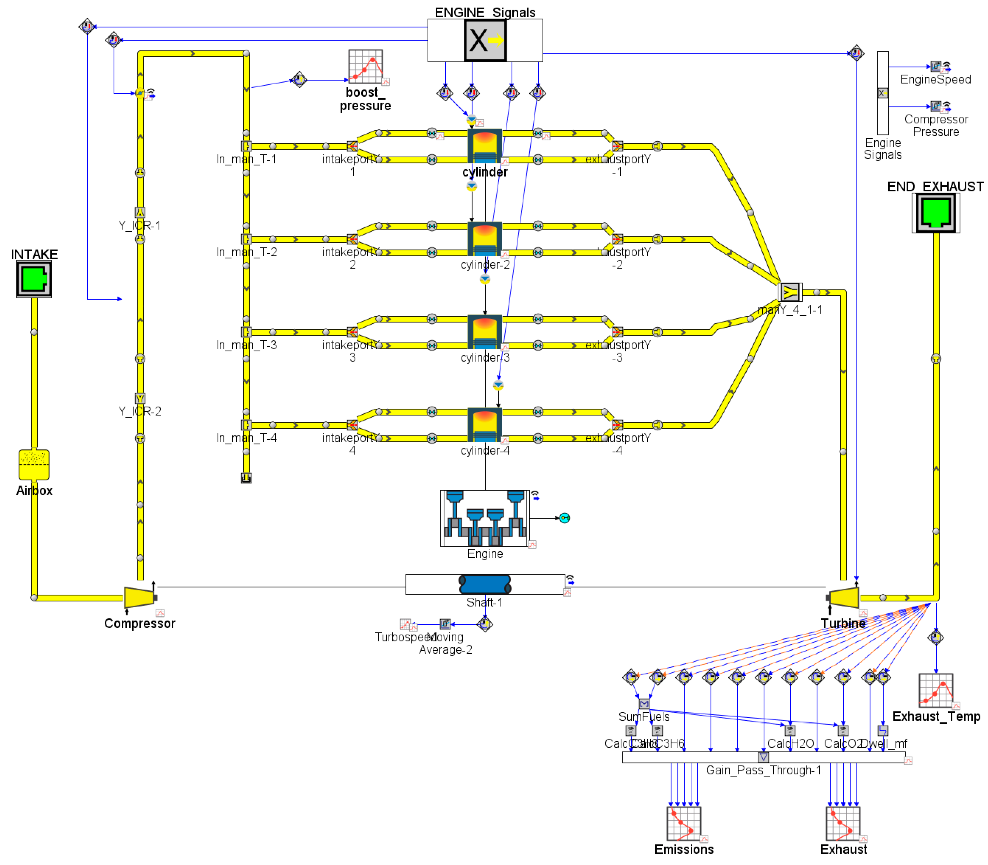
The GT-SUITE model was developed to simulate the TWC behaviour where the TESS was integrated into the after-treatment system between the turbine and the TWC.

2.1. Engine Model

The model was created based on a 1.5 TSI EVO EA211 engine manufactured by VW and its inlet exhaust gas conditions behaviour was simulated under steady-state conditions and WLTC cycle [20]. Emphasis was placed on emissions, CO2 [21] and energy flow characteristics in exhaust gas [22]. The simplified model consists of a turbocharged gasoline engine, which is equipped with temperature sensors in the exhaust pipe behind the turbocharger turbine and sensors of individual chemical components of the exhaust gas as shown in Figure 1. The models were calibrated and validated based on the experimental data for higher consistency [23].

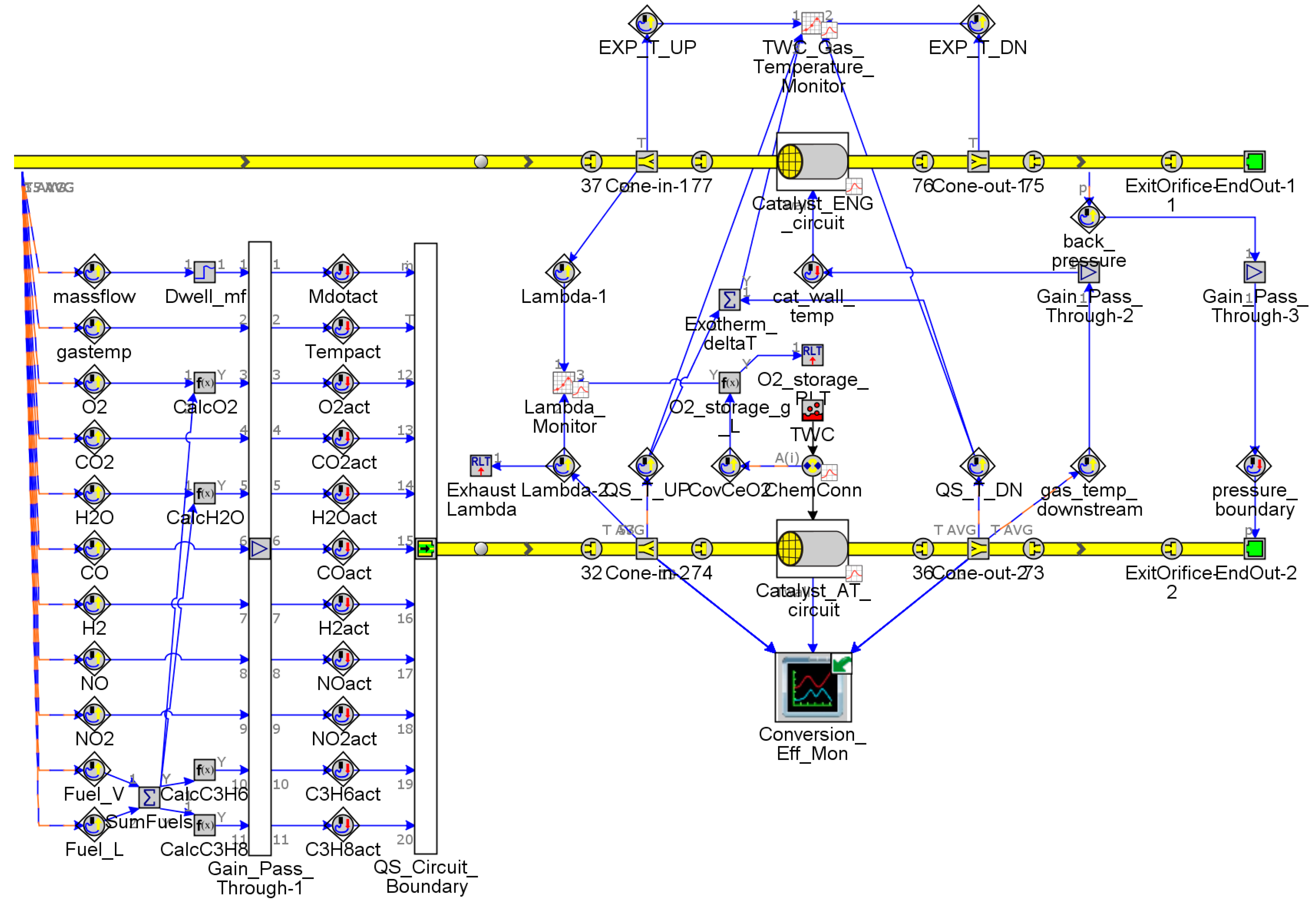
2.2. Aftertreatment System

At present, attention is being paid to the removal of exhaust emission components by measures behind the engine and in the exhaust pipe, and the engine itself is tuned to operate with the highest efficiency. The most efficient part of the emission system is the three-way catalyst, which works under optimum conditions with an efficiency of up to 98%. The aim is, therefore, to stabilize the conditions in the exhaust pipe [24].
For an optimal design and geometry of the after-treatment systems (mainly three-way catalyst), it is necessary to know the actual temperature of the exhaust gas before it enters the system [25]. The influencing factors (mainly exhaust gas temperature) were well described in the investigation by Liu H. et al. [26]. During the operation of the engine, the temperature of the exhaust gas must reach, at a minimum, the value of the light-off temperature of the three-way catalyst   t l i g h t o f f [27]. This temperature depends on the design of the catalyst, but generally, this temperature is around 630 K [28].
The simulation model of TWC was a detailed TWC in a secondary after-treatment circuit. The original base model of 1.5 TSI EVO was combined with the after-treatment model TWC by Ramanathan and Sharma, which uses a published reaction mechanism for a passenger car TWC [29]. A secondary circuit is used to solve the reactions using the quasi-steady (QS) flow solver, which can shorten the computation time. The various monitors show the TWC conversion efficiency, the exhaust lambda, the oxygen storage, the temperature upstream and downstream of the TWC and the ∆T across the TWC [30] (See Figure 2).
The number of HCs is calculated for a combination of:
  • C3H6 (faster-oxidizing HC)
  • C3H8 (slower-oxidizing HC)
The calculation considers a balanced reaction of fuel and excess water vapor and converts to the HCs with excess oxygen:
F U E L + 1.0587   H 2 0 = > 2.6433 ( 0.8   C 3 H 6 + 0.2   C 3 H 8 ) + 0.5293   O 2
The HC ratios are determined for 80% faster oxidizing and 20% slower oxidizing as was assumed in GT-Suite models as default values. These percentages are on a molar basis.

2.3. Design of the Thermal Energy Storage System (TESS)

The TESS can be used upstream of the catalytic converter to heat the exhaust gas, or directly integrated into or around the catalyst [31]. In this study, the upstream TESS design was implemented as an additional heat exchanger (basic function of TESS is illustrated in Figure 3). This configuration offers the advantage of simpler production and the possibility of additional installation in the already created exhaust pipe. In addition, no changes are required to the catalyst itself. The exhaust gas may reach the optimal temperature faster after a short engine-off period [32].

2.3.1. Problem Description
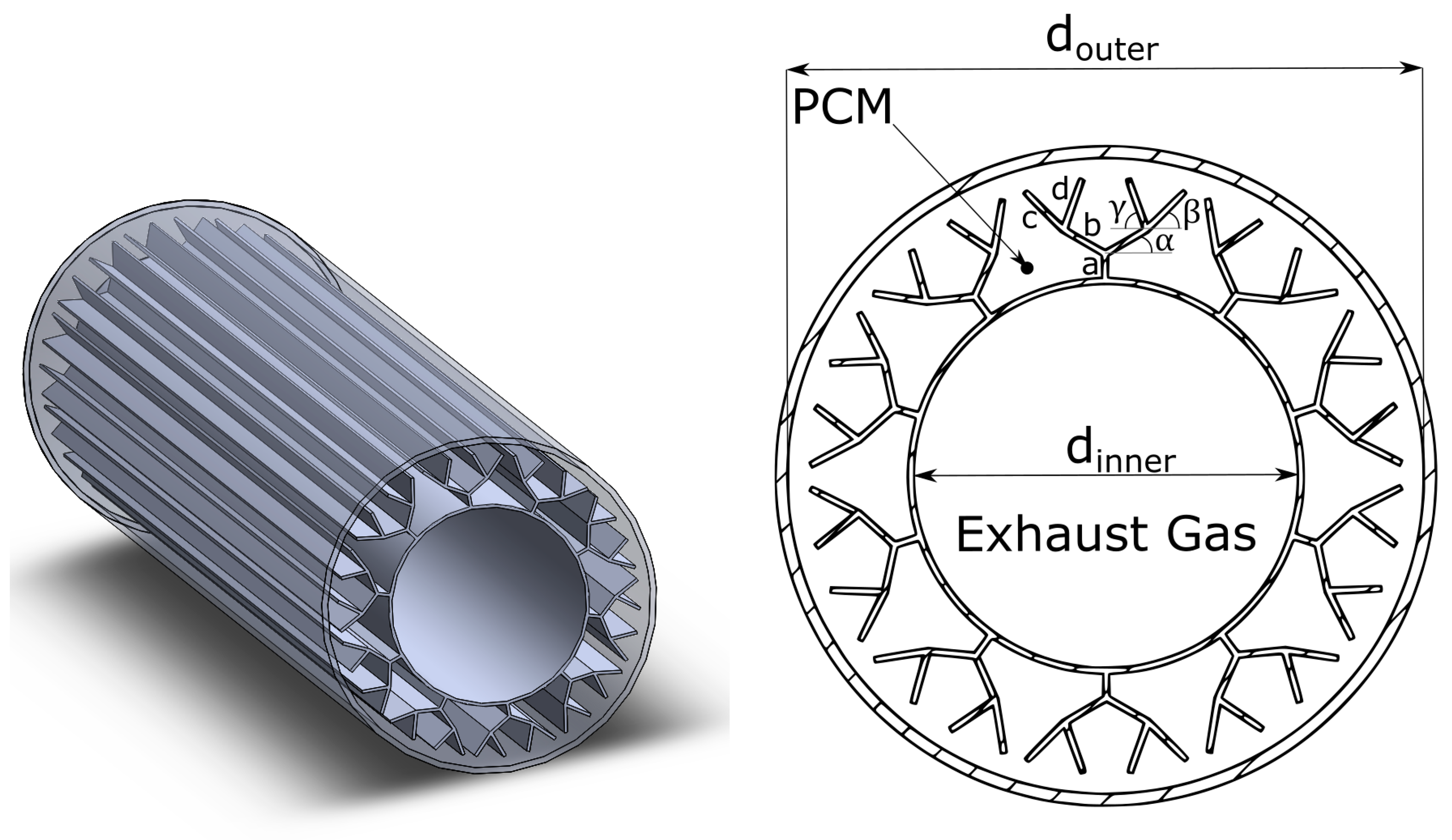
The main assumption in this paper is that conduction is the dominant heat transfer type form. This assumption is based on the previous investigation. Stritih et al. [33] reported good agreement between experimental and numerical results obtained by ignoring natural convection heat transfer in the solidification process. Therefore, in solidification simulation, velocity variables and the natural convection heat transfer can be ignored. The governing equations for this problem can be stated as follows [34]:
Continuity equation:
d m d t = b o u n d a r i e s m ˙   .
Momentum equation:
d m ˙ d t = d p A + b o u n d a r i e s ( m ˙ u ) 4 C f ρ u | u | 2 d x A D K p ( 1 2 p u | u | ) A d x   .
Energy balance equation:
t = ( ρ H ) + ( ρ v H ) = ( λ T ) + S   .
The enthalpy H is calculated [35]:
H = h + Δ H   ,
and the latent heat content Δ H is defined as:
Δ H = β L   ,
where ρ is density; v is fluid velocity; λ is thermal conductivity; S is source term; h is the sensible enthalpy; β is the liquid fraction; and L is the latent heat of the material.
The total Energy can be also written as the sum of sensible and latent heat energy [36]:
E t o t a l = E s e n s i b l e + E l a t e n t = ( 1 β ) m c s p d T + β m L + β m c l p d T ,
where c s p is specific heat capacity in solid phase and c l p for liquid phase.

2.3.2. Geometry

The basic concept of the TESS system was inspired by the construction of double pipe heat exchangers. In the inner pipe flows the exhaust gas and this pipe is covered in PCM material [37]. The amount of the material was picked as a result of compromise of the different requirements. First, to gain bigger energy storage it is necessary to have a higher amount of the material. On the other hand, with more material, the charging time of the system increases. (The TESS geometry is illustrated in Figure 4 with its dimensions listed in Table 1).
As was described in a paper written by Kh. Hosseinzadeh [38], the usage of the fins on the outside wall of the inner pipe will bolster the heat transfer rate by a huge amount, especially in the solidification process, where the convection does not play a sizeable role due to the dominancy of conduction throughout the whole operation. In the comparison of tubes with no fins, with longitudinal fins and tree shape fins, the tree-like shaped fins proved to be the best configuration [35].
The overall layout of the engine, with the TESS system and TWC, is shown in Figure 5. Also shown are the principal connections in the TESS, where the PCM mass is connected to the body with defined material properties, the cross-sectional area and the distance to the center of the mass.

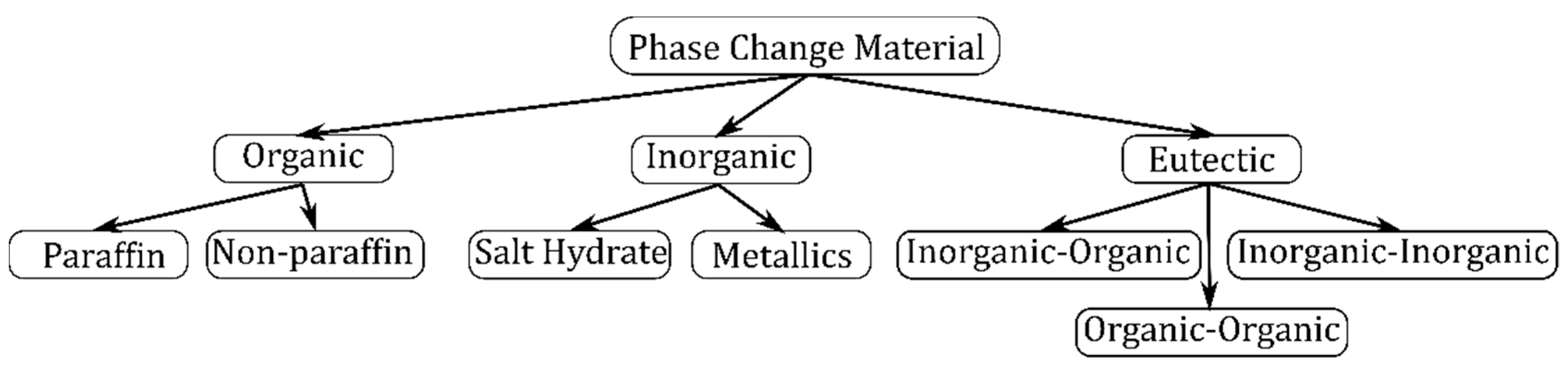
2.3.3. PCM Material Selection

Phase change materials (PCM) are materials that can store latent heat. The energy transfer occurs when a material changes its form from solid to liquid and vice versa. This is called phase change. These PCM materials (unlike conventional materials) store and release heat at an almost constant temperature. They also have 5–14 times higher volumetric heat capacity compared to sensible storage materials [16]. However, these materials must exhibit certain desirable thermodynamic, kinetic and chemical properties [39]:
Chemical properties:
  • Chemical stability
  • Non-corrosiveness, non-toxic, non-flammable and non-explosion
  • No degradation after a large number of cycles
Thermodynamic properties:
  • High density, high specific heat and high thermal conductivity
  • Melting in the desired temperature
  • High latent heat of fusion
  • Small volume change and low vapor pressure
Economics:
  • Abundant
  • Available
  • Cost-effective
The PCMs can be differentiated into three groups: organic, inorganic and eutectic. Organic PCMs are mainly paraffin and non-paraffins organic materials. Inorganic materials have the highest resistance to high temperatures and are divided into salt hydrate materials and metallic materials (Figure 6). A eutectic is a minimum-melting composition of two or more components, each of which melts and freezes congruently, forming a mixture of the component crystals during crystallization [40].
These criteria must be fulfilled for optimal selection of a PCM material for TESS. Based on the parameters of the used catalyst, the light-off temperature of the catalyst is determined to be 630 K.
PCM materials can receive/emit heat during their phase transformation. The melting point of the PCM material should be equal to this temperature for optimal operation of the emission system. In fact, because it is not possible to achieve all heat transfer without losses, it is necessary for the phase transformation temperature of the material to be higher than this minimum temperature:
t m i n     t l i g h t o f f .
At the same time, the melting temperature needs to be low enough so that the PCM can change its phase during the vehicle operation. The material with the lowest possible phase transition temperature will have the advantage of rapid charging of the container, as the material melts first. However, it also discharges faster in the event of low gas temperatures. The amount of energy that such a material can store is often smaller.
Another requirement for PCM materials is resistance to high temperatures, which can reach up to 1000 K in gasoline engine values.
Finally, materials are also required in terms of chemical stability, corrosion resistance and other negative effects. In this respect, it is impossible to use different acids and highly reactive chemicals due to safety measures and restrictions in vehicle production.
Based on a search of available materials, only PCM materials based on dehydrated salts meet these requirements. The stabilization temperature was chosen up to 670 K to make the catalyst work as efficiently as possible. As samples, three materials, whose properties are described in Table 2, were picked.
For all three samples, measurements of the exhaust gas temperature stabilization capability will be made by first warming the heat storage tank to fully charge the storage tank. Subsequently, the charging and discharging of the tank will also be measured.

3. Results and Discussion

The simulation results of the exhaust temperature pulsation and its stabilization by TESS are presented in this section. The effect of different PCM materials and operation conditions of the engine are discussed.

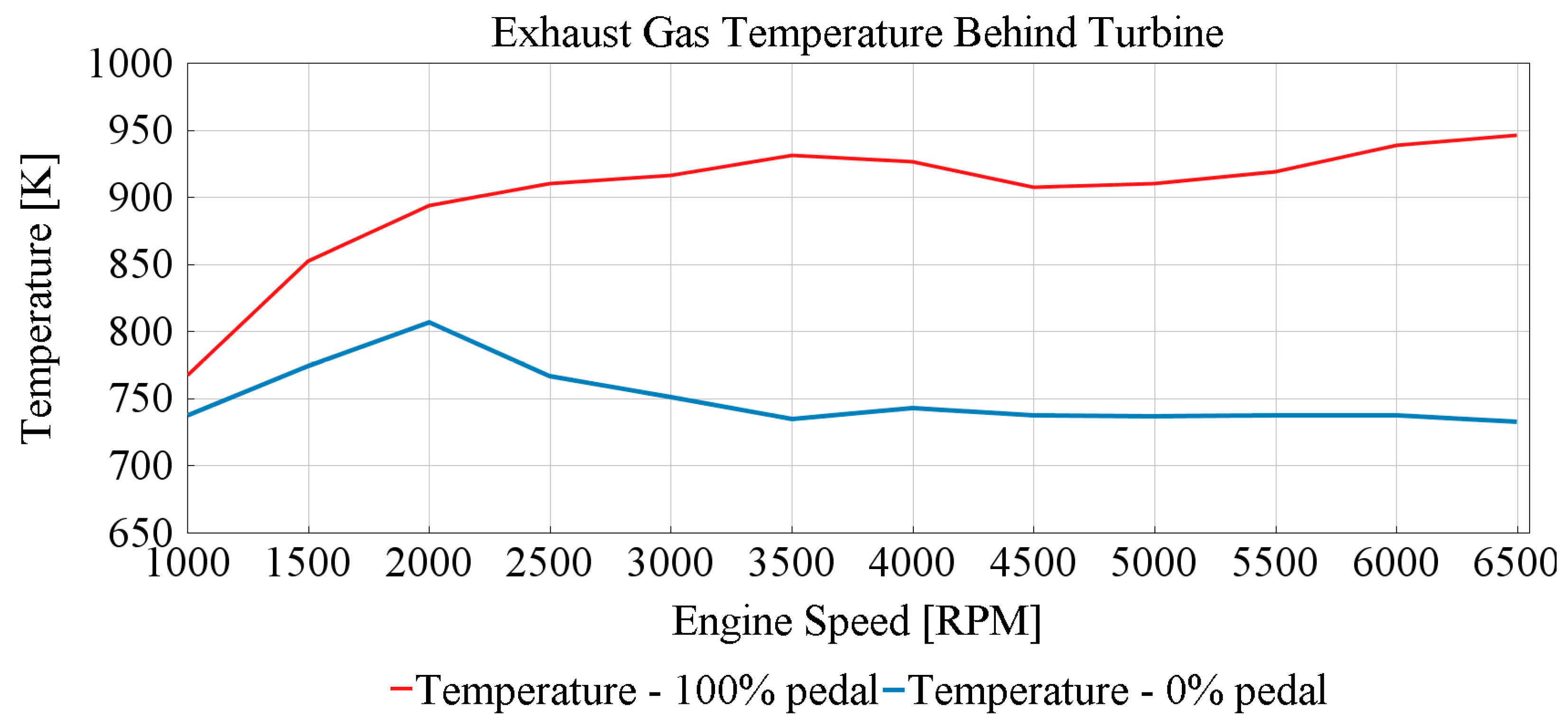
3.1. Exhaust Temperature Pulsations

The engine speed was prescribed directly, but the engine load was described by the throttle opening angle.
The first two cases were the engine performance characteristic and engine idling. These steady-state cases were necessary to calculate the maximum and minimum exhaust gas temperature in the operation range of the engine. The temperature was calculated in 12 steps in the range of the engine speed 1000–6500 min−1. The throttle was fully opened (accelerator pedal fully pressed) and closed (accelerator pedal fully released).
These two figures (see Figure 7) show the resulting exhaust gas temperature behind the turbine. However, it is almost impossible for the engine to reach these temperature values. These values only represent possible maximum values for the chosen parameters.
The transient state of the engine operation shows that the temperature dynamically changes its value corresponding to the changes in the load and the speed of the engine (Figure 8). During the partial load (and full load), the temperature is high enough for the efficient work of the catalyst. However, during the low speed and load conditions, the value of the temperature is lower than the light-off temperature of the catalyst, so it does not meet the basic condition of the effective work of the three-way catalyst described in Equation (8). This causes a reduction in the efficiency of the catalyst and thus an increase in exhaust emissions.

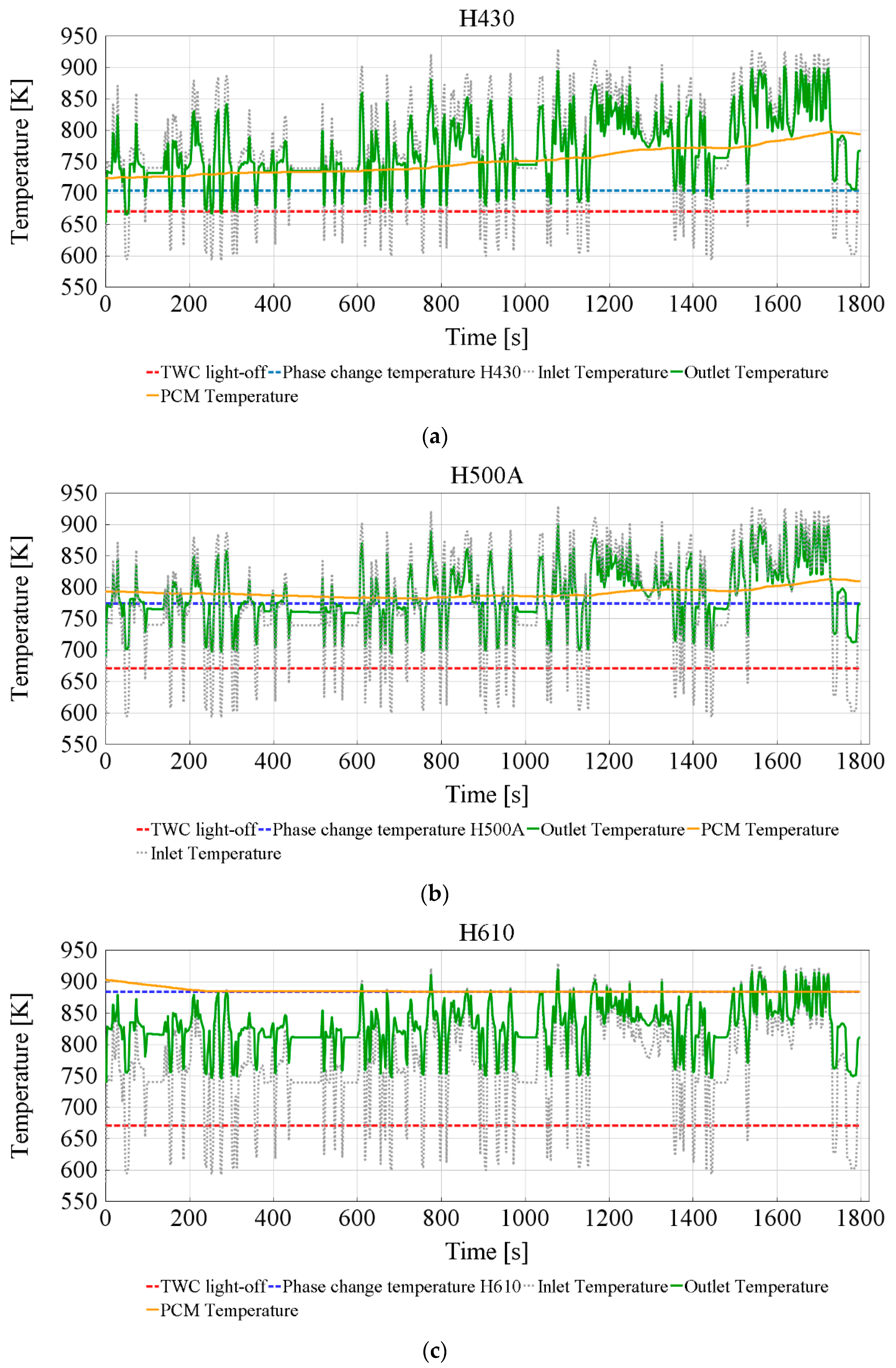
3.2. Effect of the TESS
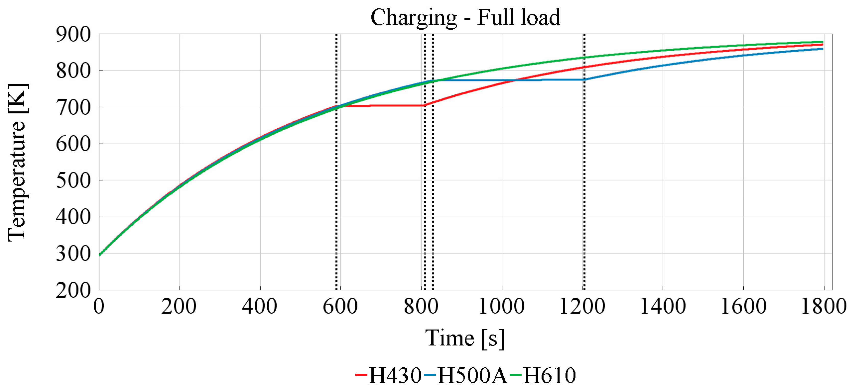
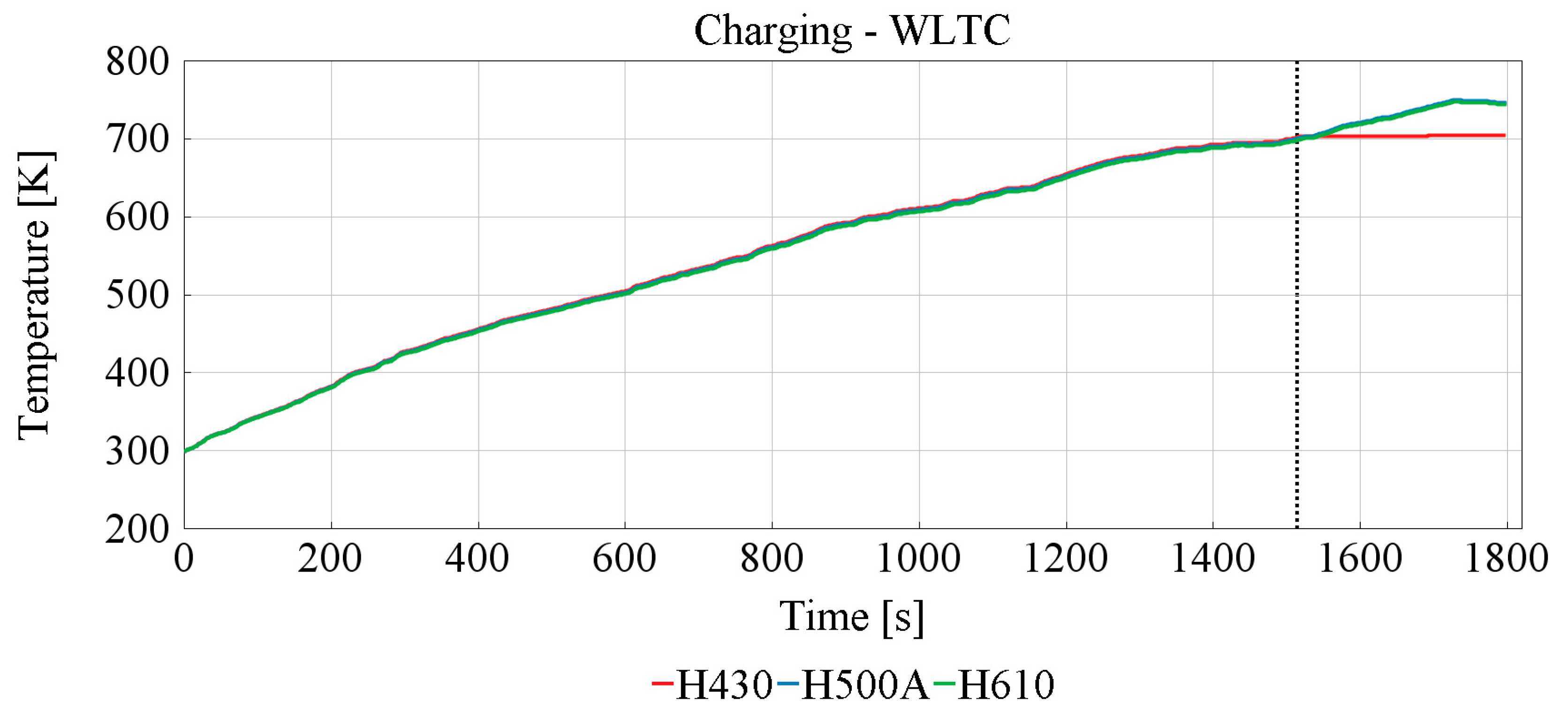
The thermal behavior of the TESS with three types of PCM material was simulated and compared to the reference exhaust gas temperature without TESS.
Figure 9 illustrates the effect of the TESS on the exhaust gas during the WLTC cycle. For the first case, the TESS was chosen to be fully charged (PCM is fully liquified)—also called a hot start. For all three materials, the exhaust temperature was above the light-off temperature throughout almost the whole course, and under highly dynamic conditions (fast change in engine speed and load), the TESS was capable of reducing the pulsations, owing to the release of its energy to the exhaust. Furthermore, for PCM H430, the mean value of the exhaust temperature was higher than its phase-change temperature during the whole cycle, so its state of charge remained still, and its temperature continued to increase (Figure 9). This effect also occurs with the usage of H500A in higher speed conditions (in high- and very high-speed parts of the cycle), however, in low and medium speeds, the mean temperature is lower than the phase change temperature and the TESS is discharged.
On the other hand, the PCM H610’s phase change temperature is too high—the mean temperature of the exhaust gas is lower than this value. This means that TESS is discharging during the whole driving cycle, however, if the TESS is fully charged, it also stabilizes the exhaust gas temperature.

Charging TESS

In this section, the heating behavior of the TESS system has been investigated to evaluate its thermal energy retention capability. The initial temperature of the after-treatment system was assumed to be at the atmospheric temperature of 25 °C, with the PCM material having the same initial temperature and being fully solidified. The charging capability was investigated for two different cases. The first was the full load and speed of the engine for 1800 s. The second case was investigated under the WLTC cycle driving conditions. The time when the material reached the melting point, and the duration of the phase change, were monitored. During this period, the PCM earned the thermal energy of the exhaust gas and stored it, firstly as sensible heat energy, and then, during melting, as latent heat energy. The melting is an isothermal process (constant temperature), so the heat transfer rate remains constant and the liquid fraction increases.
As shown in Figure 10, each material requires a different amount of time to reach its phase-change temperature. The first PCM sample, H430, requires 600 s to reach its phase change temperature and 200 s to fully melt. The sample H500A reaches its temperature after 830 s and its phase change lasts 380 s. The last sample, H610, does not reach its phase change temperature in this 1800 s long duration (Table 3).
However, only the PCM H430 has the capability to reach the phase change temperature (it requires 1509 s), and it does not fully melt during this cycle (see Figure 11). The other two materials do not reach the phase change temperature (see Table 4).

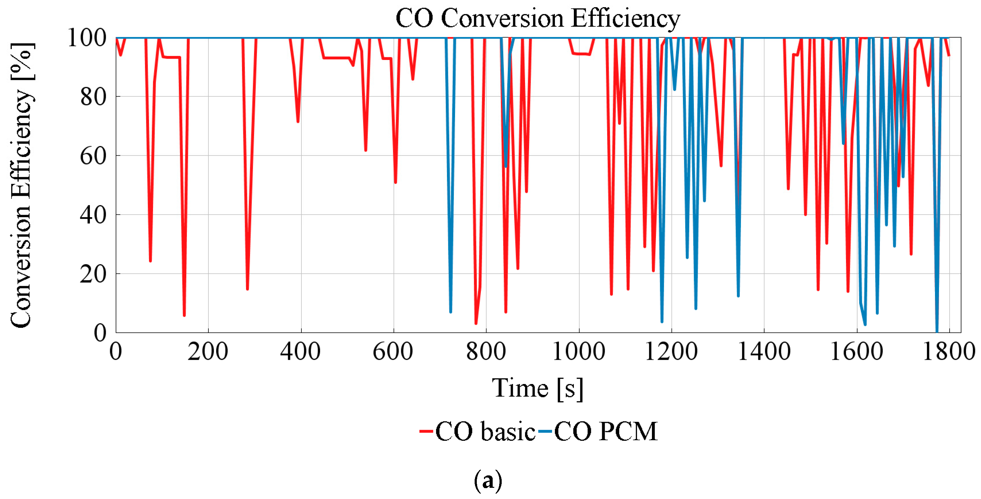
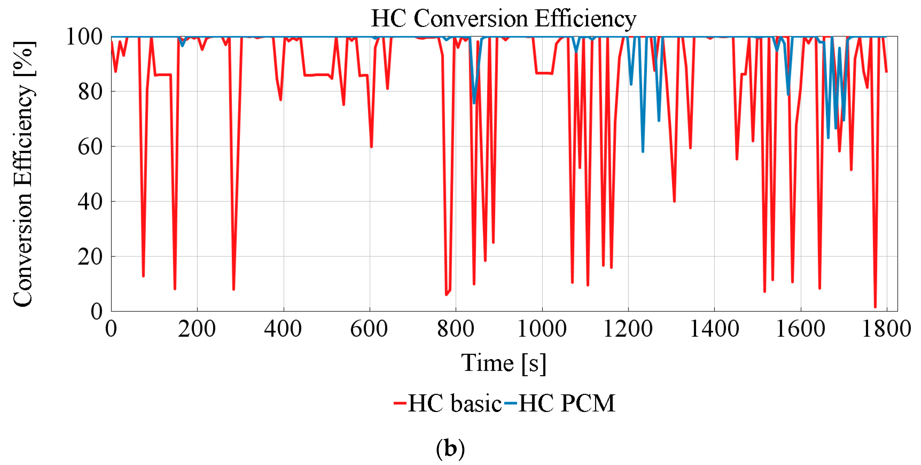
3.3. TWC Performance

Considering the hot-PCM-start condition, the stored thermal energy in the PCM helps to maintain the TESS outlet temperature above the light-off temperature of the catalyst, particularly during low and medium speed phases of the WLTC (Figure 9). This increases the conversion efficiency in the TWC, resulting in a 93.65% average conversion efficiency of the CO (compared to 85.43% efficiency without PCM) and a 93.92% average conversion efficiency of the HC (compared to 83.24% efficiency without PCM). The results indicate that an 8.2% reduction in CO emissions and a 10.6% reduction in THC emissions can be achieved just by using the TESS during the WLTC cycle compared to the reference case (Figure 12).

4. Conclusions

In this paper, a thermal energy storage system (TESS) was introduced into the after-treatment system to reduce the exhaust gas temperature pulsations and increase the efficiency of the three-way catalyst (TWC). This system included a phase change material (PCM) to store the thermal energy as a form of latent heat. The geometry of the TESS was inspired by the double pipe heat exchanger with tree-like fins on the outer wall of the inside pipe. The design was investigated and optimized based on the vehicle’s after-treatment requirements. Preliminary investigations showed that the exhaust gas temperature pulsates and that, during the WLTC cycle, its value reaches a lower temperature than the light-off temperature of the TWC in many points and the after-treatment system is less effective in these points. Three different PCM materials were examined as a potential energy storage medium. All three materials were capable of reaching their phase change temperature under the full-load conditions. They were also capable of stabilizing the temperature above the light-off temperature under hot-start conditions. However, this capability during WLTC and cold-start conditions only showed the PCM material H430, with the time to reach a melting point being 1509 s, and it was picked as an energy storage medium for TESS. The TESS, with PCM H430, proved to reduce the cumulative CO and HC emissions by 8.2% and 10.6%, respectively, during the drive. Lastly, owing to the stabilization of the exhaust temperature and conditions in the exhaust and TWC, a reduction in fuel consumption was also achieved, which was directly proportional to the reduction of CO2 emission. For further investigations of the effect of the TESS system with PCM materials, it is necessary to make a detailed simulation of the TESS with emphasis on heat transfer surfaces and heat transfer itself. Lastly, the laboratory experiments to evaluate the simulations results will be taking place.

Author Contributions

Conceptualization, M.B. and J.S.; methodology, M.B., J.S. and D.S.; formal analysis, M.B. and J.S.; investigation, M.B., J.S. and D.S.; validation M.B., J.S. and D.S.; writing—original draft preparation, M.B.; writing—review and editing, M.B. and J.S.; visualization, M.B.; supervision, J.S. All authors have read and agreed to the published version of the manuscript.

Funding

The Specific research on BUT FSI-S-20-6267.

Institutional Review Board Statement

Not applicable.

Informed Consent Statement

Not applicable.

Data Availability Statement

The data presented in this study are openly available.

Acknowledgments

The authors gratefully acknowledge funding from the Specific research on BUT FSI-S-20-6267.

Conflicts of Interest

The authors declare no conflict of interest.

Abbreviations

C3H6Propene
C3H8Propane
COCarbon Monoxide
CO2Carbon Dioxide
H2OWater
HCHydrocarbons
NOxNitrogen Oxides
O2Oxygen
PCMPhase Change Material
TESSThermal Energy Storage System
TWCThree-Way Catalyst
WLTCWorldwide-harmonized Light duty vehicle Test Cycle

References

  1. European Commission. The European Green Deal; European Commission: Brussels, Belgium, 2019; Volume 53, p. 24. [Google Scholar]
  2. European Commission. Combined Evaluation Roadmap/Inception Impact Assessment. 2020. Available online: https://ec.europa.eu/info/law/better-regulation/have-your-say/initiatives/12313-European-vehicle-emissions-standards-Euro-7-for-cars-vans-lorries-and-buses (accessed on 19 February 2022).
  3. Guillen, N.; Rico-Pérez, V.; García, A.G.; Lozano-Castello, D.; Bueno-López, A. Three-way catalysts: Past, present and future. Edición Espec. 2012, 79, 114–121. Available online: https://www.researchgate.net/publication/260407090 (accessed on 19 February 2022).
  4. Koltsakis, G.C.; Stamatelos, A.M. Catalytic automotive exhaust aftertreatment. Prog. Energy Combust. Sci. 1997, 23, 1–39. [Google Scholar]
  5. Macián, V.; Monsalve-Serrano, J.; Villalta, D.; Fogué-Robles, Á. Extending the potential of the dual-mode dual-fuel combustion towards the prospective EURO VII emissions limits using gasoline and OMEx. Energy Convers. Manag. 2021, 233, 113927. [Google Scholar] [CrossRef]
  6. Duan, X.; Liu, Y.; Zhou, X.; Zou, P.; Liu, J. Experimental investigation energy balance and distribution of a turbocharged GDI engine fuelled with ethanol and gasoline blend under transient and steady-state operating conditions. Therm. Sci. 2020, 24, 243–257. [Google Scholar] [CrossRef]
  7. Pan, M.; Qian, W.; Wei, H.; Feng, D.; Pan, J. Effects on performance and emissions of gasoline compression ignition engine over a wide range of internal exhaust gas recirculation rates under lean conditions. Fuel 2019, 265, 116881. [Google Scholar] [CrossRef]
  8. Shahbakhti, M.; Ghazimirsaied, A.; Koch, C. Experimental study of exhaust temperature variation in a homogeneous charge compression ignition engine. Proc. Inst. Mech. Eng. Part D J. Automob. Eng. 2010, 224, 1177–1197. [Google Scholar] [CrossRef]
  9. Twigg, M.V. Progress and future challenges in controlling automotive exhaust gas emissions. Appl. Catal. B Environ. 2007, 70, 2–15. [Google Scholar] [CrossRef]
  10. Yusuf, A.A.; Inambao, F.L. Effect of cold start emissions from gasoline-fueled engines of light-duty vehicles at low and high ambient temperatures: Recent trends. Case Stud. Therm. Eng. 2019, 14, 100417. [Google Scholar] [CrossRef]
  11. Hamedi, M.; Doustdar, O.; Tsolakis, A.; Hartland, J. Thermal energy storage system for efficient diesel exhaust aftertreatment at low temperatures. Appl. Energy 2018, 235, 874–887. [Google Scholar] [CrossRef]
  12. Johar, D.K.; Sharma, D.; Soni, S.L.; Gupta, P.K.; Goyal, R. Experimental investigation on latent heat thermal energy storage system for stationary C.I. engine exhaust. Appl. Therm. Eng. 2016, 104, 64–73. [Google Scholar] [CrossRef]
  13. Gong, C.; Si, X.; Liu, F. Combustion and emissions behaviors of a stoichiometric GDI engine with simulated EGR (CO2) at low load and different spark timings. Fuel 2021, 295, 120614. [Google Scholar] [CrossRef]
  14. Tu, R.; Xu, J.; Wang, A.; Zhai, Z.; Hatzopoulou, M. Effects of ambient temperature and cold starts on excess NOx emissions in a gasoline direct injection vehicle. Sci. Total Environ. 2020, 760, 143402. [Google Scholar] [CrossRef] [PubMed]
  15. Pielecha, J.; Skobiej, K.; Kurtyka, K. Exhaust Emissions and Energy Consumption Analysis of Conventional, Hybrid, and Electric Vehicles in Real Driving Cycles. Energies 2020, 13, 6423. [Google Scholar] [CrossRef]
  16. Jaguemont, J.; Omar, N.; Van den Bossche, P.; Mierlo, J. Phase-change materials (PCM) for automotive applications: A review. Appl. Therm. Eng. 2018, 132, 308–320. [Google Scholar] [CrossRef]
  17. Charvat, P.; Stetina, J.; Pech, O.; Klimes, L.; Ostry, M. Experimental investigation of stabilization of flowing water temperature with a water-PCM heat exchanger. EPJ Web Conf. 2014, 67, 02046. [Google Scholar] [CrossRef]
  18. Korin, E.; Reshef, R.; Tshernichovesky, D.; Sher, E. Reducing cold-start emission from internal combustion engines by means of a catalytic converter embedded in a phase-change material. Proc. Inst. Mech. Eng. Part D J. Automob. Eng. 1999, 213, 575–583. [Google Scholar] [CrossRef]
  19. Kaltakkıran, G.; Ceviz, M.A. The performance improvement of direct injection engines in cold start conditions integrating with phase change material: Energy and exergy analysis. J. Energy Storage 2021, 42, 102895. [Google Scholar] [CrossRef]
  20. Pavlovic, J.; Marotta, A.; Ciuffo, B. CO2 emissions and energy demands of vehicles tested under the NEDC and the new WLTP type approval test procedures. Appl. Energy 2016, 177, 661–670. [Google Scholar] [CrossRef]
  21. Tsiakmakis, S.; Fontaras, G.; Cubito, C.; Pavlovic, J.; Anagnostopoulos, K.; Ciuffo, B. From NEDC to WLTP: Effect on the Type-Approval CO2 Emissions of Light-Duty Vehicles; Publications Office of the European Union: Luxembourg, 2017; p. 50. [Google Scholar] [CrossRef]
  22. Wang, S.; Li, Y.; Fu, J.; Liu, J.; Dong, H. Numerical research on the performance, combustion and energy flow characteristics of gasoline-powered vehicle under WLTC. Fuel 2020, 285, 119135. [Google Scholar] [CrossRef]
  23. Demmelbauer-Ebner, W.; Persigehl, K.; Görke, M.; Werstat, E. The New 1.5-l Four-cylinder TSI Engine from Volkswagen. MTZ Worldw. 2017, 78, 16–23. [Google Scholar] [CrossRef]
  24. Steiner, T.; Neurauter, D.; Moewius, P.; Pfeifer, C.; Schallhart, V.; Moeltner, L. Heat-Up Performance of Catalyst Carriers—A Parameter Study and Thermodynamic Analysis. Energies 2021, 14, 964. [Google Scholar] [CrossRef]
  25. Chatterjee, D.; Deutschmann, O.; Warnatz, J. Detailed surface reaction mechanism in a three-way catalyst. Faraday Discuss. 2001, 119, 371–384. [Google Scholar] [CrossRef]
  26. Liu, H.; Li, Z.; Zhang, M.; Xu, H.; Ma, X.; Shuai, S. Exhaust non-volatile particle filtration characteristics of three-way catalyst and influencing factors in a gasoline direct injection engine compared to gasoline particulate filter. Fuel 2021, 290, 120065. [Google Scholar] [CrossRef]
  27. Majumdar, S.S.; Pihl, J.A.; Toops, T.J. Reactivity of novel high-performance fuels on commercial three-way catalysts for control of emissions from spark-ignition engines. Appl. Energy 2019, 255, 113640. [Google Scholar] [CrossRef]
  28. Nandi, S.; Arango, P.; Chaillou, C.; Dujardin, C.; Granger, P.; Laigle, E.; Nicolle, A.; Norsic, C.; Richard, M. Relationship between design strategies of commercial three-way monolithic catalysts and their performances in realistic conditions. Catal. Today 2021, 384–386, 122–132. [Google Scholar] [CrossRef]
  29. Ramanathan, K.; Sharma, C.S. Kinetic Parameters Estimation for Three Way Catalyst Modeling. Ind. Eng. Chem. Res. 2011, 50, 9960–9979. [Google Scholar] [CrossRef]
  30. Gamma Technologies. GT-SUITE: Exhaust Aftertreatment Application Manual; Gamma Technologies: Westmont, IL, USA, 2020. [Google Scholar]
  31. Kim, K.-B.; Choi, K.-W.; Kim, Y.-J.; Lee, K.-H.; Lee, K.-S. Feasibility study on a novel cooling technique using a phase change material in an automotive engine. Energy 2010, 35, 478–484. [Google Scholar] [CrossRef]
  32. Dong, D.; Moriyoshi, Y.; Kuboyama, T. Effect of porous material as heat storage medium on fuel consumption in a turbocharged gasoline engine. Int. J. Engine Res. 2020, 22, 1551–1564. [Google Scholar] [CrossRef]
  33. Stritih, U. An experimental study of enhanced heat transfer in rectangular PCM thermal storage. Int. J. Heat Mass Transf. 2004, 47, 2841–2847. [Google Scholar] [CrossRef]
  34. Siddiqui, F.; Tso, C.Y.; Chan, K.C.; Fu, S.C.; Chao, C.Y. On trade-off for dispersion stability and thermal transport of Cu-Al2O3 hybrid nanofluid for various mixing ratios. Int. J. Heat Mass Transf. 2018, 132, 1200–1216. [Google Scholar] [CrossRef]
  35. Hosseinzadeh, K.; Moghaddam, M.E.; Asadi, A.; Mogharrebi, A.; Jafari, B.; Hasani, M.; Ganji, D. Effect of two different fins (longitudinal-tree like) and hybrid nano-particles (MoS2-TiO2) on solidification process in triplex latent heat thermal energy storage system. Alex. Eng. J. 2020, 60, 1967–1979. [Google Scholar] [CrossRef]
  36. Sarkar, J.; Ghosh, P.; Adil, A. A review on hybrid nanofluids: Recent research, development and applications. Renew. Sustain. Energy Rev. 2015, 43, 164–177. [Google Scholar] [CrossRef]
  37. Geete, P.; Kumar, N.; Somani, S.K.; Gangele, A. Simulation of Double Pipe Heat Exchanger with Implementation of PCM. Int. J. Innov. Technol. Explor. Eng. 2019, 8, 658–663. [Google Scholar] [CrossRef]
  38. Hosseinzadeh, K.; Moghaddam, M.E.; Asadi, A.; Mogharrebi, A.; Ganji, D. Effect of internal fins along with Hybrid Nano-Particles on solid process in star shape triplex Latent Heat Thermal Energy Storage System by numerical simulation. Renew. Energy 2020, 154, 497–507. [Google Scholar] [CrossRef]
  39. Lone, M.I.; Jilte, R. A review on phase change materials for different applications. Mater. Today Proc. 2021, 46, 10980–10986. [Google Scholar] [CrossRef]
  40. Sharma, A.; Tyagi, V.V.; Chen, C.R.; Buddhi, D. Review on thermal energy storage with phase change materials and applications. Renew. Sustain. Energy Rev. 2009, 13, 318–345. [Google Scholar] [CrossRef]
Figure 1. Engine model.
Energies 15 02365 g001
Figure 2. Model of the aftertreatment.
Energies 15 02365 g002
Figure 3. Reduction of the exhaust gas pulsations using TESS.
Energies 15 02365 g003
Figure 4. TESS geometry.
Energies 15 02365 g004
Figure 5. (a) Overall layout of the Engine + TESS + TWC (b) Detailed view of principal connection of PCM material with body of the exchanger in TESS.
Energies 15 02365 g005
Figure 6. Classification of PCMs.
Energies 15 02365 g006
Figure 7. Exhaust gas temperature under steady-state conditions 100% and 0% accelerator pedal position.
Energies 15 02365 g007
Figure 8. Exhaust gas temperature under WLTC cycle.
Energies 15 02365 g008
Figure 9. Effect of TESS with different PCM: (a) H430; (b) H500a; (c) H610.
Energies 15 02365 g009
Figure 10. TESS charging under full load conditions.
Energies 15 02365 g010
Figure 11. TESS charging under WLTC cycle condition.
Energies 15 02365 g011
Figure 12. PCM effect on the TWC performance: (a) CO conversion efficiency; (b) HC conversion efficiency.
Energies 15 02365 g012aEnergies 15 02365 g012b
Table 1. TESS geometry dimensions.
DimensionUnitValue
d inner [mm]64
d outer [mm]108
a [mm]5
b [mm]8
c [mm]9
d [mm]9
α [°]30
β [°]45
γ [°]70
l[mm]500
Table 2. PCM materials and their properties used in the simulation.
VariableH430H500AH610
Phase change temperature [°C] 430500610
Density [kg/m3]216021402070
Latent Heat Capacity [kJ/kg]125140410
Volumetric Heat Capacity [MJ/m3]270300849
Specific Heat Capacity [J/kg K]154015551570
Thermal Conductivity [W/m K]0.5680.5670.561
Maximum Temperature [°C]140014001300
Table 3. TESS charging time for varying PCM samples (full load).
SampleReaching Phase Change Temperature [s]Phase Change Duration [s]
H430600200
H500A830380
H610NaNNaN
Table 4. TESS charging time for varying PCM samples (WLTC).
SampleReaching Phase Change Temperature [s]Phase Change Duration [s]
H4301509NaN
H500ANaNNaN
H610NaNNaN
Publisher’s Note: MDPI stays neutral with regard to jurisdictional claims in published maps and institutional affiliations.

