1. Introduction
In recent years, soaring energy prices, the intensification of the greenhouse effect, and the deteriorating situation of energy supply and demand have made energy shortage and environmental problems become the theme of global energy problems. An alternative solution is to replace traditional induction motors with high-efficiency permanent magnet (PM) motors [
1]. High-speed motors have the advantages of high power density and can be directly connected to high-speed loads, which improves the efficiency and reliability of the motor system and reduces energy consumption. Turbines and other fields have been widely used.
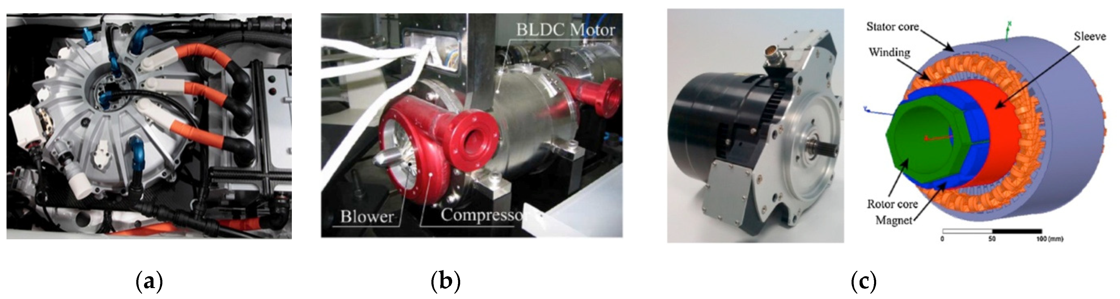
Figure 1 illustrates several typical applications of high-speed motors [
2].
Surface-mounted high-speed permanent magnet motors have the advantages of simple structure, small loss, and high power density, and are a research hotspot in the field of high-speed motors [
5]. The permanent magnet of the surface stick permanent magnet motor is considerate to the surface of the rotor mandrels, and the permanent magnet material has high compressive strength but low tensile strength. When the rotor of the motor runs at high speed, the permanent magnet cannot bear the huge centrifugal load, so a sleeve must be set outside the permanent magnet [
6]. The sleeve, as the core component of the rotor of the surface-mount permanent magnet motor, needs to have the characteristics of low eddy current loss and high strength and can provide pre-pressure for the permanent magnet to ensure that the rotor parts are not separated during operation.
The high-speed development of the motor system has put forward higher requirements for motor strength design. On the aspect of surface mount motor strength design, the rotor sleeve, as a key component of the system, has the characteristics of high running speed, high load-bearing capacity, and long-running life, leading to design and manufacturing difficulties. In recent years, the design and manufacture of high-speed permanent magnet motor sleeves have become a hot issue. Common sleeve materials include carbon fiber, glass fiber, and other high-strength fiber-reinforced composite materials.
Figure 2 shows the carbon fiber-reinforced composite sleeve rotor used in a brushless DC (BLDC) machine, as well as high-strength special alloy materials such as Inconel718 and titanium alloy.
For rotors of the same diameter, composite sleeves tend to be thinner than metal sleeves and can withstand higher speeds, and produce lower eddy current losses [
7]. At present, among the high-speed permanent magnet motors with a composite material sleeve successfully prepared at home and abroad, the highest power is the 8 MW surface mounted high-speed permanent magnet motor developed in the United States [
8], which is used to match with the gas turbine and has a rated speed of 15 kr/min. The maximum speed is the rotor developed in the Netherlands for the micro-milling spindle [
9], with a speed of up to 200 kr/min.
Figure 3 shows the power-speed distribution of a motor with a carbon fiber sleeve.
With the wide application of fiber-reinforced composite sleeves in surface-mounted permanent magnet motors, the research and development of high-performance fiber-reinforced composite sleeves have gradually deepened, and the development goal of research into its stress is mainly “accurate stress design”, “efficient prestressing preparation”, and “high-reliability use” to comprehensively improve the power density and stability of the motor system. The above-mentioned development goals include three levels of meaning: first, the influence factors such as motor structure and service conditions are combined, the sleeve prestress field and stress concentration phenomenon are comprehensively considered, and the sleeve stress field is accurately and efficiently designed; next the sleeve is prepared with high efficiency and low damage; finally, the high reliability of the sleeve is guaranteed through the three-level test of the material, sleeve sample, and rotor prototype.
Figure 4 shows the main research content of stress design and manufacturing of composite sleeves.
In order to achieve the goals of “accurate stress design”, “efficient prestress preparation” and “high-reliability use” of composite sleeves, this paper summarizes four key technologies involved in the design and preparation of high prestressed composite sleeves, as follows:
(1) Material research to match the requirements of high-speed, high-power density motors is the basis for sleeve research and application. The use of high-strength, low-density composite materials to prepare the sleeve can effectively reduce the thickness of the sleeve structure, improve the pre-tightening effect of the sleeve, and improve the motor efficiency and power density. To meet the sleeve requirements of high strength and a high preloading effect, it is necessary to comprehensively consider factors such as the actual working conditions of the rotor and the cost of the rotor and select an appropriate material system.
(2) Reasonable stress design is key to ensuring the safe and stable operation of the rotor. The sleeve stress is directly related to the rotor’s structural integrity and service safety. The minimum sleeve stress should meet the prestress required for the rotor structural integrity, and the sleeve stress concentration caused by the structure and the sleeve stress increment caused by the rotor service conditions should also be considered, to ensure that the maximum stress of the sleeve is always less than the allowable strength of the material.
(3) The preparation method with high efficiency and low damage has difficulty realizing the application of sleeve engineering. The two-step prestressing manufacturing method of winding first and then press-fitting has the disadvantages of a complicated preparation process and easy damage to the rotor. The one-step prestressing manufacturing technology of large tension winding with low damage and high preloading effect has obvious advantages.
(4) Test characterization is key to ensuring sleeve quality and safety in use; the experimental test is the most basic and direct method to evaluate the stress design and preparation quality of the composite sleeve.
2. Application of Sleeve Composite Materials
With the development of high-performance fiber-reinforced composite materials, a variety of materials are available for the application of high prestressed sleeves. The main normal temperature properties of common sleeve materials are shown in
Table 1. It can be seen that fiber-reinforced composites have the characteristics of low density, high strength, and high resistivity [
7]. The surface linear velocity of the high-power, high-speed motor rotor is high, the strength of non-magnetic metal cannot meet the requirements, and with metal as a conductor, the eddy current loss is large. When the linear velocity of the outer surface of the rotor is higher than 150 m/s, the strength of the glass fiber composite material cannot meet the demands of the rotor [
10]. Carbon fiber composite material is the most common sleeve composite material with high strength and low high-frequency eddy current loss and is suitable for high-power permanent magnet motors [
11]. For the rotor with an outer edge linear velocity of more than 250 m/s, carbon fiber is the best choice for the sleeve material [
9]. Zhang F et al. [
12] determined the sleeve of the motor with the same speed and power by design and compared the non-magnetic alloy, semi-permeable alloy, and carbon fiber composite sleeve under different working conditions of static, cold rotation, and hot rotation. The stress distribution characteristics and design laws of the three material sleeves are summarized. It is found that: (1) the stress response of alloy sleeve decreases with the increase in rotor temperature, while the carbon fiber sleeve does not change much; (2) for rotors with a high surface speed, the thickness of the carbon fiber sleeve is much smaller than that of the alloy sleeve; (3) the rotor eddy current loss of the carbon fiber sleeve is much smaller than that of alloy sleeve; (4) the temperature rise in the carbon fiber sleeved motor is much smaller than that of the alloy sleeved motor. Although the thermal conductivity of carbon fiber is poor, the eddy current loss of the carbon fiber sleeve is low, resulting in a small temperature rise.
At present, the sleeve is a mostly thermosetting composite material. Thermosetting resin has poor toughness, a long curing cycle, low production efficiency, and the prestress relaxation caused by curing, resin flow, and other factors in the molding process is obvious, while the pre-tightening effect is not good. To improve the pre-tightening effect of thermosetting composites, resin modification can be used to increase the curing rate, reduce the curing temperature, and reduce the stress relaxation caused by resin flow and mold expansion. Liu [
13] developed thermosetting resin for efficient wet winding, which has a low curing temperature and short application period and can achieve rapid curing. The influence of resin curing heat is small, which is conducive to improving the pre-tightening effect and high forming efficiency.
In recent years, high-performance thermoplastic composites have shown great performance advantages in industrial applications due to their advantages of high damage tolerance, high service temperature, short processing cycle, environmental protection, and recycling [
14]. The resin matrix of thermoplastic composite prepreg is polymerized polymer. The resin has good load transfer characteristics, can withstand higher forming prestress, and can be consolidated in situ. The forming efficiency is high, the stress “freezing” is realized, the stress relaxation is small, and the demand for a high pre-tightening sleeve is matched. High-prestressed molding has a very low tolerance for raw material damage. Most of the existing imported or domestic thermoplastic prepreg materials need to be used after cutting, which inevitably causes fiber damage and material waste in the process of cutting. Chen et al. [
15] developed a narrow-band preparation platform, which can avoid fiber damage caused by slitting. In the follow-up, it is necessary to further study the mechanism and composite mechanism of high-performance thermoplastic resin impregnation carbon fiber and optimize the process to achieve low-cost and high-efficiency preparation of a high-prestressed special narrow-band prepreg sleeve.
Due to the poor thermal conductivity of fiber-reinforced composite materials, some scholars have compared the loss and heat generation of rotors sleeved with different materials. Zhang F et al. [
12] compared the rotor loss of non-magnetic alloy, fiber composite, and semi-permeable alloy sleeved rotors and found that the eddy current loss of fiber composite material was the smallest at no-load and under load and was smaller than that of the alloy sleeve by about an order of magnitude. Under the same cooling conditions, the rotor temperature rise of the fiber composite material is also the smallest. In order to ensure the safe and stable operation of the rotor system and meet the requirements of the rotor life, many researchers have studied the rotor thermal field and designed a cooling system for the rotor. By designing a reasonable cooling system, the rotor temperature can be controlled to meet the material and structural requirements [
16]. The research on rotor eddy current loss and thermal field is relatively mature, and the cooling methods are also more diverse. This paper mainly focuses on the stress design and prestressing manufacturing content of the rotor sleeve. The rotor loss, thermal field, and cooling issues are indeed issues to be considered in rotor design, but this is not the focus of this article, so it will not be discussed extensively.
Suitable composite material is the basis of the research of high-performance motor sleeves. At present, sleeve composite materials are still in the development stage. In order to meet the requirements of advanced motors with high speed and high power density, it is urgent to develop a material system with high efficiency, low cost, and a high pre-tightening effect.
3. Stress Design of the High Prestressed Composite Sleeve
In the case of selecting the sleeve material, a reasonable sleeve stress design is key to ensuring the safe and stable operation of the rotor. The stress design of the composite material sleeve is mainly composed of a prestressing design and stress concentration calculation, which affects the structural integrity of the rotor during operation and determines the safety of the composite material sleeve and rotor [
17].
3.1. Design Principle of Sleeve Stress
Sleeve stress design is a multi-boundary condition comprehensive design; existing researchers mainly consider the material strength, the structural integrity of the sleeve, rotor electromagnetism, heat dissipation, and other factors.
When the sleeve material is selected, the maximum stress of the sleeve must be less than the allowable strength of the material [
12,
18,
19,
20,
21]. The design of sleeve stress should not only consider the allowable strength of the material but also ensure that all parts of the rotor do not separate at any temperature or speed [
9,
10,
16,
22,
23,
24,
25]. The magnetic steel is not usually separated from the mandrel [
9,
10,
24,
25], and the magnetic steel is not separated from the sleeve [
16]. Fang et al. [
24] believed that for the surface attached rotor, the magnetic steel and the sleeve would always be in contact under the action of centrifugal load, so it was only necessary to ensure contact between the magnetic steel and the mandrel. Therefore, the key to the sleeve stress design is to ensure that at all operating speeds and temperatures, there is no separation between the magnetic steel and the mandrel, and the maximum stress of the sleeve does not exceed the allowable value of the material. The stress conditions for the rotor sleeve of a surface-mounted high-speed permanent magnet motor are as follows [
25].
where
σs,m is the tangential stresses of the sleeve and the magnetic steel,
σc is the contact pressure between the magnetic steel and the core shaft, Ω is the speed, Ω
max is the maximum speed,
Tmin and
Tmax are the lowest and highest possible temperatures of the rotor.
The above formula points out the conditions to be met in the design of sleeve stress but does not quantify the sleeve stress. Zhou et al. [
26] quantitatively calculated the minimum pre-pressure required by the sleeve by calculating the centrifugal force of the magnetic steel on the condition that the precompression stress produced by the sleeve on the magnetic steel is not less than the centrifugal force of the magnetic steel.
In addition, other functional conditions of the rotor need to be considered. When the compressive stress provided by the sleeve to the magnetic steel is constant, the greater the thickness of the sleeve, the smaller the stress of the sleeve, and the greater the safety margin of the sleeve [
25,
27]. However, the increase in sleeve thickness will increase the gap between the magnetic steel and the stator, resulting in a decrease in magnetic flux density [
25] and a reduction in motor efficiency. The composite material is a bad conductor of heat, the thickening of the sleeve is not conducive to the cooling of the rotor, and the high temperature of the rotor leads to a loss of magnetic steel. When designing the sleeve, factors such as the sleeve stress, motor electromagnetic condition, and rotor heat dissipation should be considered comprehensively. Damiano et al. [
23] comprehensively considered electromagnetic, mechanical, and other design factors, and proposed to take the minimum volume as the design goal of the sleeve. Shen et al. [
21] took minimization of sleeve thickness as the main objective of the sleeve design.
Mises equivalent stress was used to evaluate the stress level of composite materials by some researchers [
9,
23,
28,
29]. Mises stress was usually used to characterize isotropic materials and was not suitable for composite materials. do Nascimento et al. [
29] pointed out that the Mises stress was only used to evaluate the results of the stress analysis and could not be used as a failure criterion for composite sleeving because it was valid only for isotropic materials. Zheng et al. [
30] used the Cai–Hu failure criterion to judge the failure of the composite material sleeve. Wang et al. [
25] used the Tresca criterion to judge the failure of the composite material sleeve.
In a word, the existing research considers the design principle of material strength and rotor structural integrity but fails to provide the optimal value and design basis for comprehensively considering the strength, stress, electromagnetic, heat dissipation, and other related parameters of the sleeve material, and lacks the quantitative optimization calculation principle.
3.2. Calculation Method of Sleeve Stress
At present, the analytical method and finite element method are used to analyze the stress of composite sleeves. The analytical method is suitable for the preliminary design of the rotor sleeve because of its advantages of small computation and high efficiency [
18]. The finite element method is often used to analyze the stress of the sleeve and the non-uniform temperature field of the sleeve in complex rotor structures.
3.2.1. Analytic Method
By simplifying the motor rotor to a multilayer two-dimensional disc, an analytical model is established, based on the theory of elastic mechanics and material constitutive equation, space rotation circle of stress and displacement equation, combined with the rotor interference between the surfaces in quantity, and according to the stress continuity boundary conditions, by the known rotor size, amount of interference between the contact surface, and the rotor speed. All the coefficients in the stress and displacement equations of the rotor can be obtained, and then the sleeve stress [
9,
18,
21,
31,
32,
33,
34,
35,
36,
37] can be obtained, and the stress field of the sleeve affected by temperature [
21,
31,
32,
33,
34,
35,
36] can also be obtained by taking into account the stress–strain relationship of the material during thermal expansion.
In actual design and manufacturing, there may be an adhesive layer between the rotor mandrel and the permanent magnet [
18,
34]. Liu et al. [
34] established a rotor stress distribution model with an adhesive layer. According to the theory of elasticity and thermodynamics, the analytical solution of the radial displacement of the inner and outer surface of the rubber layer and the stress of the sleeve are obtained.
By analyzing the influence of rotation speed and temperature changes on the interference amount, the static pressure and working pressure between the sleeve and permanent magnet can be calculated according to the interference amount to obtain the sleeve stress [
38,
39].
In recent years, researchers [
10,
17,
26,
28,
39,
40,
41] have adopted a prestressed forming method that is more suitable for the sleeve of fiber composite materials, namely the high-tension torsional winding method, also known as the carbon fiber binding method.
Figure 5 shows the section of the motor sleeve for winding molding. Compared with the traditional winding method, by selecting appropriate winding material, improving winding equipment, and optimizing the winding process, the winding tension of fiber composite material is greatly improved, and the pre-pressure of the permanent magnet is provided while the sleeve is prepared, and damage to the complex process and parts caused by interference assembly is avoided.
Binder et al. [
10] proposed that if the composite sleeve is regarded as a thin shell structure, Formula (2) can be used to calculate the pressure caused by the winding tension. If the sleeve is regarded as a thick shell structure, Formula (3) is used to calculate the pressure generated by the winding tension.
where,
pc,prestress is the pressure generated by winding,
σt,prestress is the winding tension,
hb and
rb are the thickness and radius of the composite layer, respectively,
ri and
ra are the inner and outer radius of the winding layer, respectively.
Zu et al. [
17,
40,
41,
42] considered stress-elastic relaxation after multi-layer winding. Based on the static equilibrium equation of the ring and the anisotropic material constitutive equation, the radial and annular stress equations of the composite material were obtained. The annular stress of the winding layer was obtained by combining the stress of the winding layer and the boundary conditions of the inner and outer layers. The annular stress of the inner layer after the n-th winding layer was calculated by the elastic superposition effect, and then the sleeve stress was obtained.
The method of reducing the rotor to a two-dimensional disk can simply and directly calculate the sleeve stress of the integral magnetic steel rotor but cannot calculate the sleeve stress of the partitioned magnetic steel rotor. The method of calculating the sleeve stress by the known interference and winding tension can obtain the sleeve stress, but it can only be used to check the sleeve stress under the known sleeve stress boundary condition and cannot realize the stress design for the rotor sleeve.
For the block magnetic steel structure, the compressive stress of the sleeve caused by the centrifugal action of the magnetic steel during the high-speed rotation of the rotor can be calculated [
26,
28,
43]. Zhou Y et al. [
26] believed that the stress and strain of partitioned magnetic steel generated by the centrifugal load was different from that of the overall annular magnetic steel. Due to the continuous material structure of the overall annular magnetic steel, there was stress between the elements of the magnetic steel, while there was no stress between each block of the partitioned magnetic steel. Therefore, the centrifugal load of each piece of magnetic steel acts directly on the inner surface of the sleeve. The centrifugal load of block magnetic steel generates pressure on the inner surface of the sleeve [
28].
where
ρm refers to the density of magnetic steel,
Rmo, and
Rmi, respectively, refer to the outer radius and inner radius of magnetic steel,
ω refers to the rotor speed.
Do Nascimento et al. [
29] comprehensively considered the centrifugal load of the sleeve, magnetic steel centrifugal load, and interference fit to calculate the stress of the rotor sleeve.
To sum up, the method of calculating the sleeve stress with known interference and winding tension can only be used to calculate the stress after known boundary conditions and loading of the sleeve. If the sleeve stress needs to be designed, other boundary conditions need to be added. The design of the sleeve stress can be quantified by the centrifugal load calculation of magnetic steel. The analytical method can design and calculate the prestress of the sleeve according to the simplified rotor condition, but the real rotor structure is complicated and there is stress concentration, so the analytical method cannot accurately solve the problem.
3.2.2. Finite Element Method
The block magnetic steel structure is complex, the fiber-reinforced composite material has anisotropy, the rotor service speed is very high, the experimental conditions are harsh, and the analytical method is difficult to calculate. By using finite element analysis, the precise and detailed stress distribution of the sleeve can be obtained, which can be used as a continuation and supplement of experimental research, and the influencing factors of the sleeve stress can be analyzed and discussed.
Borisavljevic et al. [
9] used the ANSYS software for finite element modeling and analysis, and the PLANE82 element for 2D structural modeling. Researchers [
17,
41] used the ABAQUS finite element simulation software to establish a rotor finite element model and used the equivalent temperature field method to simulate winding tension, that is, assigning a thermal expansion coefficient and temperature field to the winding layer, using virtual thermal stress to simulate fiber stress generated by winding tension, and establishing a contact element between layers to simulate relaxation of the winding layer. Zu et al. [
41] established a quarter model and set symmetric constraints on the symmetry plane of the model in order to improve the computational efficiency. Zhou et al. [
17] simulated the layer-by-layer winding process by using the Model Change function of the ABAQUS finite element simulation software.
Most studies show that the computational results of the analytical method and finite element method are similar [
9,
17,
22,
29,
34,
35,
41,
44]. However, Chen et al. [
45] found that because the edge effect of permanent magnet and magnetic pole filling was considered in the finite element model, there would be a certain error between the analytical solution and the finite element results. Wang [
28] believed that, if the laminated structure of composite materials was not considered in the finite element modeling, the analytical solution of tangential stress of the sleeve under rotation would have a large deviation from the finite element solution. do Nascimento et al. [
29] found that the computational resources used by the analytic method were much smaller than those used by the finite element method.
For most sleeves, the thickness is thin and the structure is relatively simple. When the calculated rotor can be simplified as a two-dimensional disk, the radial and circumferential stresses at any position inside the sleeve can be obtained by the analytical method. In this way, a relatively accurate stress value can be quickly obtained for a rotor with a simple structure, and the calculation efficiency is high. However, if the axial difference or the segmented magnetic steel structure is considered, the finite element method needs to be used to calculate the rotor stress value. Such rotor stress calculation is more in line with the actual stress distribution, but the amount of calculation is large. The sleeve designer can choose an appropriate calculation method according to the boundary conditions for the calculation of the sleeve stress and the requirements of the calculation results.
3.3. Influence Factors and Rules of Sleeve Stress
Composite material has a strong integration of design and manufacturing characteristics, analysis of sleeve stress influence factors, and reasonable design of rotor sleeve and rotor structure, can reduce the stress concentration of the sleeve, and can effectively improve the safety of the sleeve. In recent years, through the analytic method and finite element method, scholars have mainly studied the influence factors of the prestress field and stress concentration.
3.3.1. Factors Affecting Prestress Field of Sleeve
In order to ensure the integrity of the rotor structure, the sleeve is formed by interference assembly and tension winding to form a certain amount of prestressing, and the prestress is used to restrain the centrifugal action of the rotor at high speed.
The prestress of the sleeve is formed by interference assembly. With the increase in interference, the greater the circumferential stress of the sleeve, the greater the radial pressure of the sleeve on a permanent magnet. When the compressive stress required by the permanent magnet is constant, the greater the interference, the greater the annular tensile stress of the sleeve, and the smaller the thickness of the sleeve required, but it should be ensured that the sleeve stress is less than the allowable stress of the material. When the linear velocity of the outer surface of the rotor is constant, the thickness and interference of the sleeve decrease proportionally with the decrease in the outer diameter of the rotor. When the outer diameter and speed of the rotor are constant, the interference amount of the sleeve depends on the maximum annular tension stress of the sleeve. The larger the annular tension stress is designed, the larger the interference amount will be [
18].
In recent years, prestress of the sleeve formed by tension winding has been widely explored. Zu et al. [
17,
40,
41] analyzed the stress distribution of a sleeve prepared by three tension winding systems of equal tension, equal torque, and taper tension, and obtained the tension winding system of equal residual stress distribution by an iterative method. It is found that the sleeve thickness of an equal tension winding system is the smallest, the sleeve thickness of the conical tension winding system and equal residual stress distribution is relatively thicker, and the sleeve thickness of equal torque distribution is the thickest. Equal tension winding is more suitable for a rotor with a thin carbon fiber sleeve, while an equal stress distribution is more suitable for a rotor with a thick sleeve.
Figure 6 shows the radial compressive stress of permanent magnets under different winding tensions.
Through the analysis of the tension system, molding process, material, and other influencing factors in the tension winding, the relationship between the winding tension and residual tension is obtained in the existing research, and the stress field required by the design of the winding tension is obtained. Springer et al. [
46,
47,
48] assumed that the continuous winding of fiber bundles was simplified to the external pressure superposition of thin-walled cylinders of multilayer composite materials. Considering the winding and curing process, five submodels were established, including thermochemistry, fiber motion, stress–strain, pore diffusion, and strength assessment. Zhao et al. [
49,
50] numerically simulated the fiber wet winding process by using the finite element method, and analyzed the temperature, curing degree, resin viscosity, permeability, residual stress, and fiber content in the winding and curing process, and the fiber content measured in the experiment was consistent with the calculated value. Xing et al. [
51,
52] studied the relationship between toroidal winding tension and residual tension of rigid cylindrical cylinders and deformable thick-walled cylinders, as well as the differential equation of residual tension distribution after winding determined by a given winding tension. Shi et al. [
53,
54] established an analytical algorithm for the relationship between residual tension and winding tension by using the principle of stress superposition within the elastic range based on the elastic deformation of the anisotropic winding layer and the theory of isotropic thick-walled tube lining. Wu et al. [
55] proposed an optimal design method for the tension of a fiber wound thick-walled pipe and established a model and method to calculate the change of residual internal stress of composite pipe caused by winding tension. Chen et al. [
56] studied the influence of the resin curing mode and period on the prestressing of composites.
In the process of rotor service, the stress of the sleeve will increase obviously due to the influence of centrifugal load and rotor temperature rise. As the carbon fiber composite material has a negative coefficient of expansion, but the mandrel and magnetic steel material in the sleeve both have a positive coefficient of expansion, the tangential stress of the sleeve increases significantly with the increase in rotor temperature, and the maximum speed of non-separation between magnetic steel and mandrel increases with the increase in rotor temperature [
9]. Du et al. [
16] pointed out that the stress of the rotor after the temperature rise can easily reach the allowable strength of the material, and the stress of the rotor at high temperatures must be accurately calculated.
The non-uniform temperature field of the rotor has little influence on the stress of the sleeve [
32,
57,
58]. Du et al. [
58] found that the influence of the temperature difference between the sleeve and permanent magnet on the sleeve stress was almost negligible, and the temperature difference between the rotor core and the permanent magnet had little influence on the stress of the sleeve. The rotor stress obtained by the isothermal model is slightly larger than that obtained by the temperature-stress coupled model.
During the rotor operation, the tangential stress of the sleeve increases slightly with the increase in rotational speed. Wang et al. [
25] pointed out that, with the increase in rotor speed, the stress concentration in the inner wall of the sleeve caused by a magnetic steel block would be intensified. Given the stress changes of the sleeve in the three states of static no temperature rise, no rotation temperature rise, and rotation with a temperature rise, the study found that the maximum stress of the sleeve is in a state of rotation with a temperature rise [
11,
24].
3.3.2. Influence Factors of Sleeve Stress Concentration
The magnetic steel structure of the surface-attached rotor is mainly divided into integral type and block type, as shown in
Figure 7 [
58]. The integral permanent magnet has the advantages of simple structure, easy processing, and high mechanical strength, but the utilization rate of the permanent magnet material is low. The structure is shown in
Figure 7a. Block permanent magnets are usually processed into tile types [
5,
18,
59]. Block magnetic steel is arranged in close rows on the outer circumference of the core shaft, as shown in
Figure 7b,c, which can reduce the eddy current loss of the permanent magnet [
24,
25] and improve the utilization rate of permanent magnet materials. The edge of block magnetic steel and the filling place between magnetic poles can easily lead to the stress concentration of the sleeve. Existing studies have analyzed the influencing factors of stress concentration and reduced the stress concentration by optimizing the rotor structure.
The densely packed segmented magnetic steel will not produce obvious stress concentration [
22,
36] but will produce bending stress at the pole gap of the sleeve, leading to stress concentration [
36]. The additional bending stress increases the maximum stress of the sleeve, and even exceeds the stress limit of the sleeve. It is necessary to add materials with a density similar to permanent magnets in the inter-pole air gap to reduce or eliminate the bending stress [
22].
However, in the above study, the clearance of magnetic steel blocks is very small. Zhang et al. [
33] analyzed the two situations when the distance between adjacent permanent magnets was 1°and 5° and found that the edge effect caused by the partition of permanent magnets would produce larger bending stress on the inner surface of the carbon fiber sleeve, and the larger the distance between adjacent permanent magnets, the greater the bending stress of the carbon fiber sleeve. Hao [
38] quantitatively analyzed the influence of pole spacing on sleeve stress by using the pole arc coefficient of the permanent magnet, which refers to the ratio of the arc length of the permanent magnet to the pole distance. It is found that the polar arc coefficient of the permanent magnet has little influence on the maximum radial stress of the sleeve but has a great influence on the maximum tangential stress of the sleeve. The maximum tangential stress increases first and then decreases with an increase in the polar arc coefficient of a permanent magnet.
Wang et al. [
25] found that when the segmented magnetic steel is in a state of compressive stress, the rotor stress remains stable, and the number of blocks has no obvious effect on stress. However, when the magnetic steel is under tensile stress, the tangential stress of the sleeve decreases with the increase in the number of permanent magnets. The analysis shows that the edge effect decreases with the increase in the number of magnetic blocks. It is found that the stress concentration of the sleeve is its maximum at the minimum operating temperature. In practice, the increase in the number of magnetic steel blocks will increase the difficulty of manufacturing. The rotor stress, loss, and manufacturing difficulty should be considered in the design.
The elastic modulus and thermal expansion coefficient of the filling between the poles will directly affect the maximum stress of the rotor sleeve at static and dynamic conditions as well as the temperature rise [
18,
36,
37,
38]. Hao [
38] found in his study that whether or not there is inter-pole filling has a great influence on the stress of the sleeve, and inter-pole filling can effectively reduce the stress concentration of the sleeve. The effect of different filling materials on the stress of the sleeve is compared. It is found that the material with a large difference between the thermal expansion coefficient and that of magnetic steel as the filling material leads to a great change in the radial stress and tangential stress of the sleeve when the temperature changes. Wan et al. [
18] found that in the case of the rotor without a temperature rise, due to the difference of material density, elastic modulus, and Poisson’s ratio, the annular tensile stress, radial compressive stress, and bending stress received by the sleeve with a stainless steel inter-pole filling were the smallest, the distribution of radial compressive stress was the most uniform, and the residual strength of the sleeve was the highest. However, when the rotor temperature rises, the residual strength of the sleeve decreases due to the thermal expansion of the material. The rotor using titanium alloy as the magnetic pole spacing has low bending stress and high residual strength of the sleeve in operation, with or without a temperature rise.
Du et al. [
58] studied the influence of the gap between the magnetic pole filling and the magnetic steel block on the stress of the sleeve and found that, in a certain range, with the increase in the gap, the tangential maximum stress of the sleeve decreases slightly.
Chen et al. [
5,
45] analyzed the stress distribution of a quad pole rotor with inner aluminum electrode filling under a static, non-temperature rise rotation, and temperature rise rotation. It is found that the contact pressure between the inner surface of the carbon fiber sleeve and the outer surface of the rotor core is approximately a square wave with a period of 90° under three operating conditions.
Chen et al. [
45] found that the inner wall of the sleeve is affected by the internal material and structure, resulting in greater bending stress and stress concentration, especially in the magnetic pole gap or filling part of the magnetic steel block. To slow down the bending stress of the inner wall of the sleeve, scholars set thin glass fiber material or metal material in the inner layer of the sleeve [
9,
10,
11,
17,
22,
32,
36,
37,
60], as shown in
Figure 8, which can effectively slow down the stress concentration of the sleeve, significantly reduce the maximum stress of the carbon fiber composite layer, and increase the reliability of the rotor, and the inner metal material can also increase the overall stiffness of the sleeve [
60].
Due to the influence of the rotor forming process, there may be a rubber layer between the magnetic steel and the mandrels. Liu et al. [
34] proposed a motor–rotor model based on the integral magnetic steel structure with inter-shaft filling and found that under high-speed and high-temperature conditions, the tangential stress of the sleeve of the rotor with inter-shaft filling is slightly smaller than that of the rotor without inter-shaft filling. There is little influence on the radial stress of the sleeve with or without inter axial filling. Zheng et al. [
30] found that for the segmented magnetic steel rotor, the rubber layer can withstand a certain magnetic steel centrifugal force, which can reduce the stress of the sleeve and improve the safety of the sleeve.
The efficiency of the current rotor design method is low because there are many factors affecting the stress of the sleeve. In the follow-up research, artificial intelligence algorithms and finite element analysis technology can be combined to nest the finite element model in the intelligent algorithm. After several iterations, the analysis and design of high-prestressed fields can be studied to further exert the use efficiency of materials and reduce the application threshold of the composite material sleeve.
4. Preparation of High Prestressed Composite Sleeve
With the development of science and technology, the speed of the high-speed permanent magnet motor is higher, the high-speed centrifugal load caused by a structure caused by the radial tensile stress increases, and the specific technology introducing suitable radial compressive stress in advance, namely prestressing, pushes the structure stress “origin” forward to offset some or all of the high-speed rotation of the radial tensile stress. To protect the permanent magnet from damage during high-speed rotation and ensure the integrity of the rotor structure and non-separation, this special technology is prestressed manufacturing technology.
There are two kinds of prestress manufacturing technology for the composite material sleeve, which can be divided into two-step prestress manufacturing and one-step prestress manufacturing. The traditional winding tension of a smaller radial internal pressure is small, not enough to ensure that the operation process of the rotor magnet steel and spindle are not isolated; the winding sleeve assembly on the magnetic steel surface is needed, which can be made for magnetic steel preloading after the first winding interference assembly for two-step preparation of the prestressing sleeve. In recent years, researchers [
10,
17,
26,
28,
39,
40,
41] have adopted the high-tension winding forming method known as the one-step method to prepare prestressed sleeves, which provides pressure for magnetic steel through the winding tension while the sleeve is winding.
4.1. Preparation of Prestressed Sleeve by the Two-Step Method
The traditional tension-wound sleeve produces less pressure on the inner layer, which has difficulty meeting the design requirements of high-performance rotors. In order to make the sleeve produce enough pre-tightening pressure on the magnetic steel, interference assembly of the sleeve is required on the surface of the magnetic steel [
18], and the two-step method is adopted to prepare the prestressed sleeve. At present, there are two main interference assembly processes: the temperature difference method and the pressing method. The temperature difference method is to heat the inclusion part to expand or to cool the inclusion part to shrink so that the two are convenient to assemble. When the assembly body returns to normal temperature, interference will be formed between the two. The pressing method refers to the interference assembly method by which the contained part is directly pressed into the containing part by a press [
61]. A schematic diagram of the interference assembly of the composite material sleeve by the two-step method is shown in
Figure 9. Zhou [
40] assembled the sleeve interference on the surface of magnetic steel with an oil press after traditional tension winding.
The interference assembly method has some disadvantages such as complicated processes and difficult realization of interference. When the interference assembly using the temperature difference method is adopted, the thermal expansion coefficient of carbon fiber is low, and cold contraction assembly of the rotor can only be used, resulting in small interference of the contraction fit and limited pressure on magnetic steel [
24]. Interference assembly by the pressing method is prone to damage [
62] and is not suitable for the sleeve formed from fiber-reinforced composite material [
17].
4.2. Preparation of Prestressed Sleeve by the One-Step Method
With the emergence of a high-precision tension control system (>200 N/yarn), the continuous optimization of fiber wear prevention measures in the yarn path, and the development of dry winding technology with pre-impregnation, the fiber winding stress level can reach 7~15% of its strength value without damaging the fiber [
63]. By controlling the fiber tension, high-tension winding technology can exert a higher preload on the structure, replacing the traditional mechanical interference methods such as hot/cold sleeve, press-fitting, and bolt preload, realizing the manufacturing of lightweight composite structure with high prestress, high strength, and small deformation. Preparation of the prestressed sleeve by the one-step method is shown in
Figure 10. It has been well applied in high-tech electromagnetic equipment of high-speed rotating machinery such as a high-speed centrifuge rotor and composite flywheel [
63]. In recent years, researchers [
10,
17,
28,
39,
40,
41] have adopted the high-tension winding method to prepare the carbon fiber sleeve for the rotor of permanent magnet motor, and the one-step method is used to form the sleeve pre-tightening, which provides pre-tightening force for the permanent magnet while preparing the carbon fiber sleeve, and can make the stress distribution of the sleeve uniform by designing the tension of the winding layer.
Due to the elastic relaxation caused by the shrinkage of the inner composite material by the extrusion of the outer layer when the composite material is wound, the thermal relaxation caused by the mismatch between the core mold and the thermal expansion coefficient of the composite material during hot curing, and the flow relaxation caused by the pressure driving due to the decrease in the viscosity of the resin during curing, the prestress relaxation occurred during the molding process. To solve the problem of prestressing relaxation, in situ consolidation additive manufacturing technology can be used to reduce the flow relaxation during winding and the thermal relaxation during curing, to realize the efficient and high-quality preparation of components.
The thermoplastic composite material can achieve in situ consolidation and winding, and the material has only physical changes in the molding process, high molding efficiency, and short molding time, and is suitable for high-performance motor rotor sleeves. Thermoplastic composites have become a research hotspot, and many achievements have been made in materials, process equipment, and process control [
64]. Nanjing University of Aeronautics and Astronautics took the lead in studying the application of thermoplastic composite in situ forming in prestress manufacturing [
42]. Through a single-factor experiment and response surface analysis experiment, the optimal forming process considering winding tension was obtained. A thermo-mechanical coupling model was established, and the reason for prestress relaxation caused by the heat effect was analyzed by laser heating and winding experiments.
With the increase in the winding tension level, higher requirements of structural stiffness, tension uniformity, and mechanical stability are put forward for winding equipment. To prevent the influence of rotor magnetic steel on winding equipment, the moving parts of the forming equipment in the area affected by the magnetic field should be treated without magnetization. Winding yarn will have a large additional bending moment at the roll passing point, which can easily cause yarn damage. If the equipment space allows, the diameter of the roll passing should be properly enlarged to reduce the additional bending moment of the roll passing on the yarn. In the process of high-tension winding, the winding equipment carries a large load, so the structural strength and stiffness of the winding equipment should be strengthened.
In general, the existing composite sleeve is formed by two-step prestressed molding, but its process is complicated and can easily cause composite damage. One-step prestressed molding is suitable for the molding of the composite material sleeve and has a certain research basis, but the existing winding tension is low, which cannot effectively utilize the high-strength characteristics of composite material, and the subsequent research can be carried out for the high-tension winding. The prestress relaxation can be reduced by in situ consolidation. According to the special requirements of the magnetic steel rotor sleeve winding, the equipment is treated without magnetization to reduce the damage to the winding yarn and strengthen the strength and stiffness of the equipment.
5. Test of Mechanical Properties of the High Prestressed Composite Sleeve
At present, the experimental study is still the most basic and direct method for evaluating the stress design and preparation quality of composite sleeves. In recent years, the experimental studies carried out by scholars mainly include preload effect tests, strength tests, and prototype service tests. Researchers [
17,
40,
41] evaluated the pre-tightening effect of the sleeve on magnetic steel by testing the strain of magnetic steel and verified the rationality of sleeve stress design. The sample was prepared with the same material and the same process, and the strength of the sample was tested [
17,
26,
40,
41,
65] to evaluate the preparation quality of the sleeve. The rationality of the sleeve stress design and preparation quality was comprehensively investigated by manufacturing rotor prototypes and service tests of the prototype [
10,
16,
18,
36,
45,
57,
58,
59,
65].
5.1. Test of Pre-Tightening Effect
Researchers [
17,
40,
41,
42] tested the strain changes of magnetic steel under tension winding by strain gauge to evaluate the pre-tightening effect of the sleeve. The strain test experiment is shown in the figure below. Cheng [
42] tested the strain change of the winding test piece by sticking the strain gauge on the inner wall of the metal core mold to test the pressure of the composite sleeve on the metal core mold [
17,
40,
41] with strain gauges attached to the sidewall of magnetic steel to test the compressive stress of composite materials on magnetic steel. It is found that the experimental results are close to the theoretical ones.
5.2. Strength Test
To explore the strength of a fiber-reinforced composite, the samples were prepared and tested by using the same molding material and the same molding process. Zhang et al. [
65] tested the strength of the NOL ring after winding molding, and the dispersion coefficient of the sample is small. M46J/L1000 composite material has high tensile strength, modulus, and low fracture elongation, which is suitable for use as a sleeve material.
Zu et al. [
17,
40,
41] tested the strength of carbon fiber winding products under different tensions. They found that with the increase in winding tension, the strength of composite material samples first increased and then decreased, which was thought to be caused by serious fiber wear when the tension was higher.
Zhou et al. [
26] made flat samples to test the material strength and elastic modulus at 20 °C and 150 °C and found that the strength decreased at 150 °C, but the modulus did not change much. Two sleeve experimental tubes were manufactured: (1) 5 mm thickness cylinder, laying layer, and sleeve are exactly the same, testing the annular and axial strength of the sleeve, and (2) a thickness of 1.4 mm, testing the ultimate circumferential strength. The centrifugal force of magnetic steel was simulated by a water pressure test, and the strain change during loading was measured by a strain gauge. The results show that (1) the experimental values of circumferential and axial stress of 5 mm-thick samples are close to the theoretical values, and the radial displacement meets the design requirements, and (2) a 1.4 mm-thick sample test shows that the strength of composite material meets the design requirements.
The existing evaluation of the molding quality of the sleeve is mostly to test the sample of the sleeve; there was a lack of quality testing of the installed sleeve. Ultrasonic, infrared, and other non-destructive testing methods can be used to detect and evaluate the molding quality of the sleeve.
5.3. Prototype Test
No damage was found in rotor structure through rotor prototype manufacturing and rotating experiments at the rated speed [
10,
16,
65] or overload speed [
18,
36,
45,
58,
59,
66], which proves that the designed and manufactured sleeve can meet the demands of rotor strength. Moreover, the rotor has been tested for a long time [
16,
25,
58,
66], and the rotor runs stably, which proves that the rotor design and manufacture are reasonable. The high-speed permanent magnet motor prototype with carbon fiber sleeve and test platform manufactured by Zhang et al. [
59] is shown in
Figure 11.
Wang et al. [
57] conducted a destructive experiment running for a long time at extreme temperatures, resulting in cracks at the center of the sleeve under the action of thermal stress, and the loss of magnetism of permanent magnets. To avoid the above problems, high-modulus carbon fiber material can be selected to improve the safety factor of the sleeve. The anisotropy of carbon fiber material produces radial upward contraction after heating, which is conducive to the permanent magnet withstanding the centrifugal force, but at the same time, axial elongation; the sleeve assembly should leave a gap with the magnetic ring.
Binder et al. [
10] manufactured an M1 rotor filled with low-density resin material between poles and performed a rotation experiment in which sleeve failure occurred at 35,000 r/min below the rated speed, as shown in
Figure 12.
According to the theoretical calculation, the sleeve stress at 35,000 r/min is less than the allowable strength of the material. It was found that the failure position of the sleeve was close to the gap between the magnetic poles of the magnetic steel. It was judged that the failure of the sleeve might be caused by the increased stress of the sleeve caused by the temperature rise in the rotor and the effect of the axial stress on the sleeve, especially the bending stress between the poles and the stress concentration at the edge of the magnetic steel. It is consistent with finite element calculation that the maximum stress of the sleeve is between the poles.
Then, an M2 rotor without a pole gap was prepared, as shown in
Figure 13, a thin layer of glass fiber was added to the inner layer of carbon fiber to withstand the bending effect of block permanent magnet, and the bending effect was expected to be eliminated. The rotor can run stably at the rated speed of 40,000 r/min.
In summary, the existing test experiments for the performance of composite material sleeves are relatively single, and the use of advanced performance characterization methods is insufficient. There is a lack of testing of prestressing distribution and molding quality of the sleeve after preparation. At the same time, the test characterization of the rotor in service is too few, and the experimental study of real-time stress, damage, and evolution of composite sleeves are not enough. In addition, the performance of the sleeve under the influence of fatigue, vibration, and other complex loads is still lacking.
6. Conclusions and Further Study
In light of the developed analysis, the fiber-reinforced composite material sleeve has very obvious performance advantages and shows great value in the application of surface-mounted high-speed permanent magnet motors. However, the stress design and preparation of the composite material sleeve is a multi-process, multi-level, complex, comprehensive problem. In order to better apply high-performance fiber-reinforced composite materials to motor sleeves, this paper summarizes the design and manufacture of sleeve stress from the aspects of sleeve material, stress design, prestress preparation, and testing.
With the development of high-performance motors, composite sleeves must continue to improve. Based on the existing research and development status, the prospect of the development of a fiber composite sleeve is put forward:
The application of quick-curing thermosetting composite or in situ forming thermoplastic composite is the basis to improve the effect of sleeve pre-pressing.
Optimizing the design and manufacturing mode of the sleeve is the key to improving the forming efficiency of the sleeve. In order to improve the efficiency of the sleeve design and manufacture, research on intelligent design and high-tension winding should be carried out.
The follow-up could carry out the quality testing of the forming sleeve, and the detection and research of the whole life cycle of the sleeve, to ensure the safe and stable operation of the rotor.


