Article

Refueling of LH2 Aircraft—Assessment of Turnaround Procedures and Aircraft Design Implication

1
Institute of Aircraft Design, University of Stuttgart, 70569 Stuttgart, Germany
2
Institute of System Architectures in Aeronautics, German Aerospace Center (DLR), 21129 Hamburg, Germany
3
Institute of Electric Power Systems, Leibniz University Hanover, 30167 Hanover, Germany
*
Author to whom correspondence should be addressed.
These authors contributed equally to this work.
Energies 2022, 15(7), 2475; https://doi.org/10.3390/en15072475
Submission received: 2 February 2022 / Revised: 18 March 2022 / Accepted: 21 March 2022 / Published: 28 March 2022

Abstract

:
Green liquid hydrogen (LH2) could play an essential role as a zero-carbon aircraft fuel to reach long-term sustainable aviation. Excluding challenges such as electrolysis, transportation and use of renewable energy in setting up hydrogen (H2) fuel infrastructure, this paper investigates the interface between refueling systems and aircraft, and the impacts on fuel distribution at the airport. Furthermore, it provides an overview of key technology design decisions for LH2 refueling procedures and their effects on the turnaround times as well as on aircraft design. Based on a comparison to Jet A-1 refueling, new LH2 refueling procedures are described and evaluated. Process steps under consideration are connecting/disconnecting, purging, chill-down, and refueling. The actual refueling flow of LH2 is limited to a simplified Reynolds term of v · d = 2.35   m 2 / s . A mass flow rate of 20   kg / s is reached with an inner hose diameter of 152.4 mm. The previous and subsequent processes (without refueling) require 9 min with purging and 6 min without purging. For the assessment of impacts on LH2 aircraft operation, process changes on the level of ground support equipment are compared to current procedures with Jet A-1. The technical challenges at the airport for refueling trucks as well as pipeline systems and dispensers are presented. In addition to the technological solutions, explosion protection as applicable safety regulations are analyzed, and the overall refueling process is validated. The thermodynamic properties of LH2 as a real, compressible fluid are considered to derive implications for airport-side infrastructure. The advantages and disadvantages of a subcooled liquid are evaluated, and cost impacts are elaborated. Behind the airport storage tank, LH2 must be cooled to at least 19K to prevent two-phase phenomena and a mass flow reduction during distribution. Implications on LH2 aircraft design are investigated by understanding the thermodynamic properties, including calculation methods for the aircraft tank volume, and problems such as cavitation and two-phase flows. In conclusion, the work presented shows that LH2 refueling procedure is feasible, compliant with the applicable explosion protection standards and hence does not impact the turnaround procedure. A turnaround time comparison shows that refueling with LH2 in most cases takes less time than with Jet A-1. The turnaround at the airport can be performed by a fuel truck or a pipeline dispenser system without generating direct losses, i.e., venting to the atmosphere.

1. Introduction

The European Commission’s Green Deal, with the goal of carbon neutrality by 2050, also challenges the aviation industry to break new ground [1]. Hydrogen is a versatile and clean energy carrier that can be produced renewably by electrolysis [2]. Due to its higher specific gravimetric energy compared to kerosene (factor 2.8) [3], H2 could be a natural choice as a fuel for aviation. Sustainable aviation fuels are the main competitors of H2 [4]. Synthetic kerosene produced in a power to liquid (PtL) process, assuming electric energy as the power source with Carbon Dioxide (CO2) captured from the air and water as primary resources [5], is one possibility. Using synthetic fuel, the aircraft design does not change, and the airport does not require new infrastructure. On the other hand, the amount of energy required for production is larger [4], leading to a higher fuel price compared to LH2. In addition, CO2—filtered out of the air at great expense for the PtL process—is released with combustion of synthetic kerosene.
However, LH2 has a disadvantage when used as a fuel, especially in aviation, because its volumetric energy density is lower by a factor of 4.0 compared to kerosene [3]. This difference leads to larger tank volumes that can no longer be reasonably positioned in the wing and therefore require adjustments to the fuselage, leading to higher drag and therefore higher thrust requirements, i.e., less energy efficiency of the total aircraft. In principle, H2 can be stored in various aggregate states and pressure ranges leading to different densities. Cryogenic storage at LH2 temperatures of around 20 K, preferred due to its lower volume requirement, needs tank insulation to keep the heat input low. Otherwise, the LH2 would heat up, leading to evaporation and pressure increase. When the maximum tank pressure is reached, losses occur. Initial assertions indicate that an LH2 refueling process could be two to three times longer than with conventional Jet A-1 [6]. This statement is doubtful, as it is based on the assumption of keeping the same volume flow of 900 L/min [1], which is too low for Jet A-1 [7,8] and would be too low for LH2. Additionally, comparing dimensional values of different fluids with large differences in physical properties can lead to meaningless results [9]. Such a significant extension of the refueling process would have a far-reaching impact on the annual utilization and Direct Operations Costs (DOC) of the aircraft. Therefore, increasing costs for the required refueling process are considered and impacts on turnaround time are investigated. Comparison to conventional refueling with Jet A-1, together with a benchmark with the space and automotive industries, allows for an analysis of boundary conditions and limitations for LH2.
Studies on the overall impact of LH2 on aircraft design and airport infrastructure have been conducted since the 1970s [10,11,12]. However, there is limited research on the boundary conditions for the refueling process. The Tupolev Tu-155 was an experimental aircraft used to test alternative fuels on one engine in 1988/89 [13]. The uniqueness of the aircraft configuration was a chimney on the vertical tailplane, which is a feature for LH2-aircraft and crucial for explosion protection in case of venting. Airbus [14] with their Cryoplane and Brewer [15,16,17] have indicated the potential of LH2 as a fuel in aviation and provide the basis for further research and development towards LH2-fueled aircraft. Refueling is coming into focus as a potentially critical factor of LH2-powered aircraft, which could significantly reduce economic efficiency [1]. This is particularly true for short-range aircraft, where the ground time has a much greater impact on aircraft utilization compared to long-range aircraft.
Therefore, the motivation for the following work is to recapture and further develop the technical understanding of the effects of LH2 on the turnaround and refueling process based on mathematical and physical correlations. Due to the different statements of the publications, the novelty and the research gap in this paper is to show the boundary conditions, calculation methods, and analysis of the refueling system and obtain conclusions from them. Previous publications only present a final result but do not show the calculation way and method. The research gap closed by this paper is to outline the missing methods of previous years again and make them understandable. Furthermore, analytically solvable methods are preferred to save time but avoid numerical calculation and make correlations more easily visible. In addition, solutions are shown to ensure a similar turnaround time to enable a competitive LH2-powered aircraft. By understanding thermodynamic relationships, the novelty in this study is also to transfer the implications of refueling to aircraft design.
The basis for this work is the Master’s thesis by Mangold [18], which was supervised in cooperation with the University of Stuttgart and the German Aerospace Center (DLR). This thesis investigates the economic assessment of H2 short-range aircraft with a focus on the turnaround. In addition, there is a parallel publication from Hoelzen et al. [19] about the economic analysis for LH2 refueling and airport infrastructure.
In Section 2, this paper first presents the required state of the art necessary to get an overview of Jet A-1 refueling and the properties of LH2. Then in Section 3, the methodology is described to analyze the system, the procedure and boundary conditions. The results of the refueling procedure and the implications on the airport distribution are given in Section 4. Finally, Section 5 discusses the impacts on aircraft design with the gained knowledge.

2. State of the Art

This chapter presents the technologies and principles to create a relevant basis for the LH2 refueling analysis. Firstly, the boundary conditions and limitations of refueling with Jet A-1 are investigated to enable comparability. Secondly, basic properties of H2 are presented to provide relevant knowledge required for understanding the behavior of a cryogenic liquid. Finally, to reflect the handling possibilities of hydrogen, a benchmark with existing procedures in the fields of space and automotive industry is provided.

2.1. Refueling of Jet A-1

Commercial aircraft are normally fueled with single or dual connections at the bottom side of the wing. Ground refueling vehicles can be distinguished in dispenser pipeline systems and refueling trucks. The time required for positioning and connecting as well as disconnecting and removing is about 2.5 min [7]. For faster refueling of long-range aircraft, it is typically necessary to refuel on both sides of the wing in parallel. Jet A-1 has the property of an accumulator building up static electricity due to friction as it flows through a pipe [20]. The discharge of this static electricity can cause ignition of the fuel in explosive mixtures [20]. Therefore, there are limitations in the flow conditions of Jet A-1 [20,21,22], expressed through the pipe diameter d and the flow velocity v:
v · d 0.5 m 2 / s
v 7 m / s short pipe
v 3 m / s long pipe
To evaluate the comparison of the flow regime independent of the fluid, dimensional analysis can be used, which compares dimensionless numbers to ensure comparability [9]. Therefore, the simplified term v · d can be converted into a Reynolds number of R e = 2.86 · 10 5 by dividing by the kinematic viscosity ν ( T = 288.15 K ) = 1.75 · 10 6 m 2 / s [23]. Through the limitations in Equations (1) and (2), an inner hose diameter of 63.5 mm ( 2.5 in ) can be calculated, which is the same as for the ground refueling vehicle manufacturer’s specification [8]. Recalculating of single-point fueling under static electricity restrictions with the continuity equation results in a maximum volume flow of a of 1500 L/min for one hose. In dimension and weight [8,24,25], the resulting hose is a manageable load for airport staff during a working day [26]. When lifting the fuel adapter to the aircraft manually, its weight is essential for the handling options (see Section 3.12.1).
The following equation describes the transferred refueled volume V depending on the time t to the aircraft [27]:
V ˙ = V ˙ t = 0 · e α · t
V = 0 t V ˙ d t = V ˙ t = 0 · e α · t 1 α
V ˙ t = 0 defines the initial volume flow, which corresponds to the maximum flow rates calculated with the static electricity limitations. The value for the resistance of the tank and other components involved during refueling is denoted by the factor α [28].
According to Equation (4), the volume flow decreases exponentially for α < 0 . This decrease is due to the rising liquid level in the tank, leading to an increase in hydrostatic pressure and the increasing pressure losses due to closing valves in the connection between the separated tanks [27]. However, this characteristic can be explained based on the pump capacity and Bernoulli’s equation. With a constant pump power, the pump can deliver a higher volume flow at the beginning of the refueling process because the delivery pressure is still low due to a low liquid pressure head. As the liquid level rises, the pump must continuously apply a higher pressure, which leads to a lower volume flow at constant performance. This specific characteristic is represented in factor α and varies depending on the aircraft type. The refueling process α values are 0.022 min 1 for a Boeing 747 [27], 0.0145 min 1 for an Airbus A380 [27], and 0.036 min 1 for an Airbus A320 [29].
Therefore, a comparable sizeable initial flow rate V ˙ t = 0 of 1800 L / min for a single-point and 3600 L / min for dual-point refueling is used in the following study. The volume flow of 3600 L / min can be translated to a comparable energy flow of 2100 MJ / s , which is basis of the sizing of the LH2 refueling system, see Section 3.13.1. The volume flow of 1800 L / min infringes the limitations at the beginning of refueling, but the exponential reduction recaptures this. Nevertheless, these maximum values serve for the time-critical comparison with LH2.

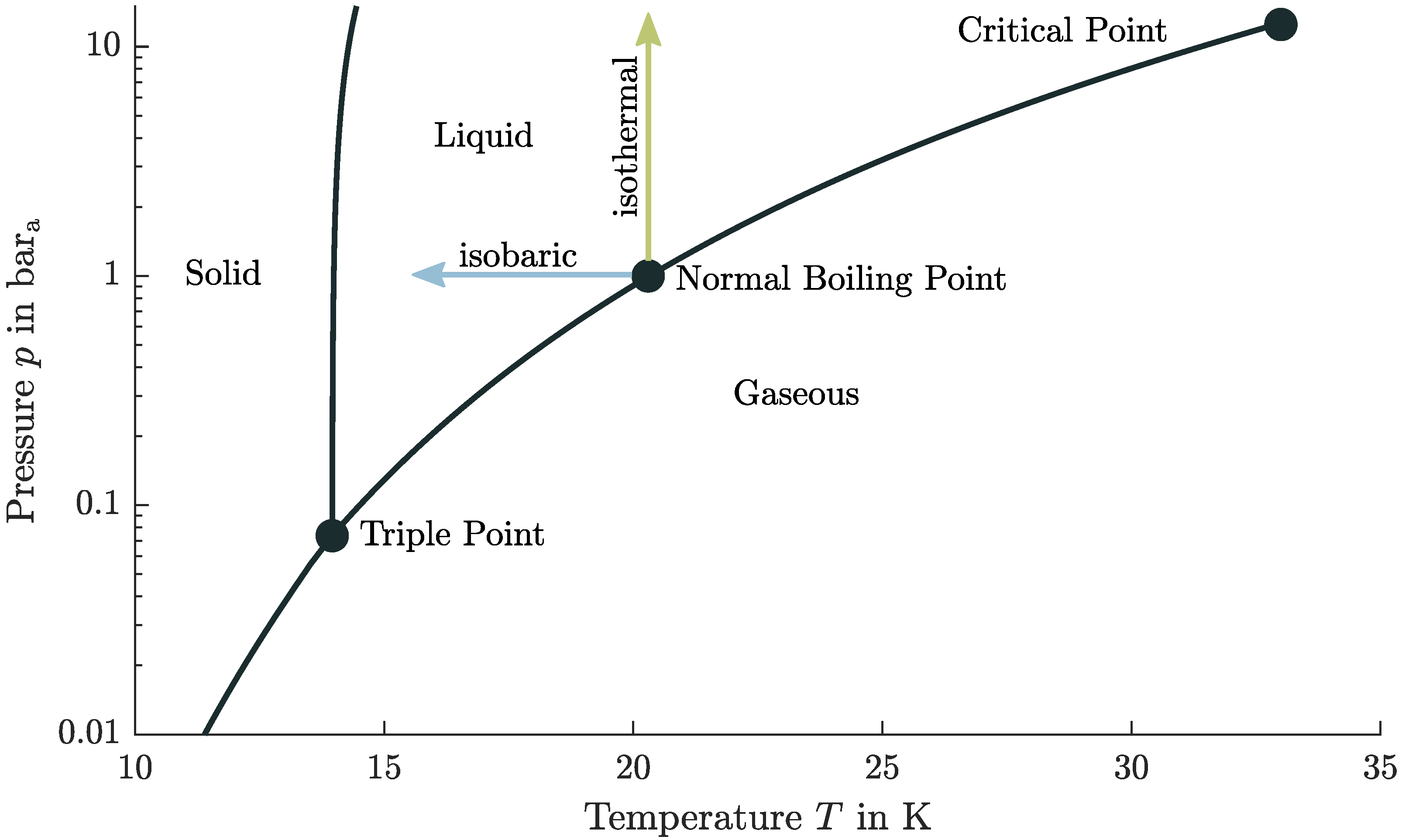
2.2. Properties of Liquid Hydrogen

The properties of H2 (independent of the phase state) have to be known to understand the following considerations and to reflect the design decisions. H2 has a Lower Heating Value (LHV) of 119.95 MJ / kg during combustion [3], defining its useful energy. When mixed with air, the flammability limits of hydrogen are between the Lower Flammability Limit (LFL) 4 vol . % and the Upper Flammability Limit (UFL) of 75.7 vol . % [30]. The minimum ignition energy of H2 is 0.017 mJ [30], which is more than an order of magnitude lower compared to Jet A-1 [23]. Aluminum alloy 6061 or stainless steel X5CrNi18-10 (AISI 304) are selected as recommended materials for a hydrogen system [30,31,32].
With respect to the thermodynamic properties of hydrogen molecules, there is a distinction in the energy level [3,33,34]. Equilibrium hydrogen refers to a mixture in thermodynamic equilibrium, which consists in liquid state of 99.8 % parahydrogen [35]. Therefore, the physical values of parahydrogen based on the database RefProp [36] are used in the following work.
Figure 1 shows a phase diagram of hydrogen. The state of aggregation is relevant as it determines the applicable system of equations, i.e., the equation for the ideal or real gas cannot be used for a liquid. Furthermore, there is a significant difference between a saturated liquid and a subcooled liquid [3,33,37]. Firstly, the density can be calculated by the temperature or pressure for a saturated (boiling) liquid and does not require both state variables. Secondly, a subcooled (compressed) liquid describes a liquid in the single-phase region (common understanding of liquid), and therefore not on the saturated liquid line. The generation of a subcooled liquid is possible by removing heat or by an isothermal pressure increase [37], see Figure 1. Thus, the temperature of the subcooled fluid is below the equilibrium temperature. The advantage of this state is that the LH2 can absorb heat without any vaporization losses until thermodynamic equilibrium is reached [3].
Another parameter for the design of LH2 tanks is the characteristic curve of vapor pressure over temperature, reflecting the behavior over time for cryogenic tanks. If the temperature of the fluid increases, the vapor pressure will also increase. This, in turn, means that if a certain subcooled level shall be maintained, the liquid pressure must also increase. This is especially crucial for tanks that do not reach equilibrium, i.e., where the tank pressure is higher than the vapor pressure.
Similar to the subcooled level, there are two simplified ways to enter this two-phase region: by an isobaric temperature increase or by a (sudden) pressure drop under isothermal conditions [37,38].
The ullage above the liquid in sealed tanks is the extra gas volume, needed to allow thermal expansion of the liquid [31]. Therefore, a two-phase mixture must be present in the tank at all times to avoid excessive pressure fluctuations [2]. However, this does not mean in general that the contents of the tank must be in the two-phase (liquid–vapor saturation) region in the T-s diagram and in a saturated state. In this thermodynamic equilibrium the ullage and liquid temperatures are equal, and the vapor pressure curve balances out, i.e., this process needs time—depending on a system between 10 min [39] and more than 4 h [40]. There must only be a gaseous component to absorb the density changes of the liquid due to the compressibility of the gas. As a result of this, the pressure in the tank does not increase excessively. Hence, in non-thermodynamic equilibrium, there can be a subcooled liquid and a hotter gas in the tank. This distinction is necessary because promptly after refueling, the content of the tank is in non-equilibrium and later in equilibrium. It can be summarized that LH2 must be treated as a real compressible fluid, i.e., close to the vapor region and two-phase phenomena. Further considerations and impacts on aircraft design based on these findings are elaborated in Section 5.

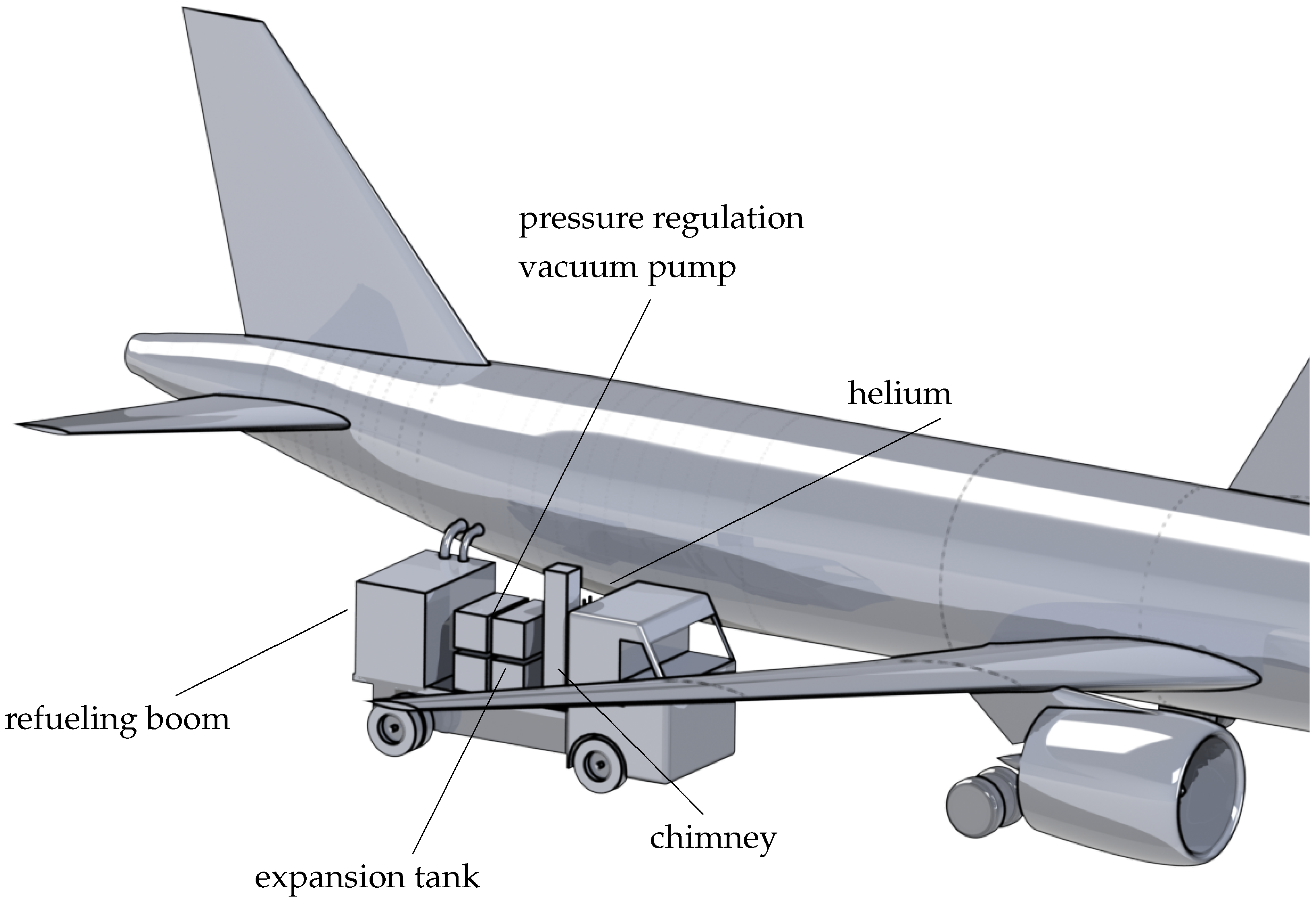
2.3. Handling Options for Hydrogen

H2 is already widely used in industry and research. Typical pressures for compressed Gaseous Hydrogen (GH2) in the automotive industry are 350 and 700 bar [41]. The standardized refueling protocol for GH2, SAE2601 [41], shows the influence on temperature and pressure level on the refueling times. The adapters for GH2 refueling in the automotive industry are standardized in SAE2600 [42]. The real gas behavior for GH2 must also be considered based on the Joule–Thomson effect, i.e., due to an isenthalpic expansion, the hydrogen heats up [3]. Therefore, a cooling system is required for high pressure GH2 refueling [3], affecting the system and increasing costs. The standardization for GH2 refueling is not applicable for LH2 because of the different requirements related to the phase state.
As there is no standardized industry norm for LH2 refueling, the following handling options are considered. One possibility that allows for handling of LH2 is the vacuum-insulated Johnston or Johnston–Cox coupling [34,43]. Due to the open connection point, after connecting and before disconnecting, for reasons of safe handling and compliance with explosion protection, a purging process is necessary [43]—so no foreign gases remain in the hoses. Helium is required for this purging process [30], as at cryogenic temperatures of 20 K, all substances except helium (boiling point of 4.2 K [35]) would freeze and block the pipe [44,45]. Helium has the further advantage of being an inert gas that does not form chemical reactions and dissolves only slightly [31]. On the downside, Helium is an expensive, non-renewable inert gas [46] that should ideally not be used in regular operation. A massive increase in helium consumption could raise the price to such an extent that using LH2 as a fuel would become uneconomical.
The other option is to perform the purging process with nitrogen and GH2 [30]. Due to the requirement to first purge the ambient atmosphere with nitrogen ( T > 80 K [30]) before purging it again with GH2 before LH2 can be introduced [30], this method is excluded because of the additional complexity and time needed.
A clean break disconnect releasing a small amount of spillage during connection and disconnection [47] is the second possibility. Evacuation and pressurization (purging) before and after refueling can be eliminated with the use of a self-sealing quick disconnect [48,49,50]. The system gauge pressure is at minimum 0.2 bar g for LH2 [51] and 1.7 bar g for GH2 systems [30,51]. This gauge pressure prevents penetration, and the system remains free of contamination.
Both variants, the Johnston disconnect and the clean break disconnect are further considered, as both methods are feasible. The technical implementation is used in nonaircraft applications, which are analyzed in the following section.

2.4. Non-Aircraft Liquid Hydrogen Refueling Applications

For dimensioning the aircraft refueling system, other refueling applications and their specifications are useful for defining aircraft refueling. A comparison with the automotive industry is based on large batches and numbers of refuelings, which must be handled by every driver with a reliable and safe refueling system. On the other hand, space applications are characterized by large individual fuel quantities, which are only required in a certain time interval. Therefore, these two non-aviation applications will be analyzed further in order to draw conclusions on aircraft refueling.

2.4.1. Automotive Industry

The automotive refueling process of LH2 is interesting as the safety regulations are high. In direct comparison, LH2 shows advantages over GH2 due to the lower storage pressure, which favorably affects leakage characteristics [52]. Nevertheless, monitoring and detecting H2 by a gas sensor is essential and follows a power supply shutdown and emergency stop system [52]. A fully automatized refueling robot for LH2 was being used at Munich Airport in 1999 [52]. This approach shows the potential safe handling and high readiness level.
The recovery system is of special importance in this context, as vaporized hydrogen must be returned from the vehicle tank [48,53]. This measure is necessary to keep the tank pressure constant and prevent it from rising. Furthermore, a cryogenic coaxial clean break disconnect is used [52,54,55] to combine the LH2 transfer and the GH2 recovery line in one disconnect. The self-closing clean break disconnect is connected in 20 s and disconnected in 10 s. The improvement in time compared to the non-clean break Johnston disconnect is more than 30% [56].
Therefore, the comparison with the automotive industry shows the potential for appropriate, safe, and time-saving use. The refueling protocol of Stewart [48] can be adopted for LH2 aircraft refuelings and applied for further standardization.

2.4.2. Space Shuttle Loading

The External Tank (ET) of the Space Shuttle is fueled with LH2 by a pressurization system [57]. To maintain the storage tank’s pressure level, some liquid flow is vaporized and injected into the ullage [43]. The diameter of the transfer pipe is d pipe = 0.254 m with a length of l pipe = 457 m [57]. For loading LH2 to the ET, a volume flow of 28.4 m 3 / min is transferred [57], which results in a Reynolds number of 1.22 · 10 7 . For simplification, this means that the term v · d is about 2.37 m 2 / s and the velocity is 9.34 m / s .
For comparison, an operating ullage pressure p of 2.2 to 2.35 bar a and venting pressure of 2.5 bar a is established for the ET [58]. The tank’s pressure is increased during the loading process [57] to prevent the LH2 from boiling through the heat input and following temperature increase. After loading, replenishing, and topping, it has to be ensured that the required fill level is maintained and continues shortly before the liftoff [57]. Moreover, the tank pressure is reduced through a vent valve to 0.01 bar g [57]. Through the pressure decrease, the LH2 boils back (flash evaporation) to a saturated state [59], which means that the temperature decreases and density rises back to Normal Boiling Point (NBP) conditions. This procedure is necessary because the required fuel mass of the mission must fit into the fixed volume of the rocket, which is designed with the density in the NBP. Thereby, the tank content is in thermodynamic equilibrium and the temperature and, consequently, also the density can be calculated from the pressure. The required fuel for the mission can thus be determined and the time to launch is not time-critical.

2.4.3. Spacex Falcon 9 Loading

SpaceX introduces a different loading procedure for their rockets as it is loaded just 35 min before liftoff [60]. This fundamentally different sequence is required because of a densification process [61]. Due to the use of a cryogenic fluid, this loading process is comparable to aircraft refueling with LH2 because the same problems and solutions arise due to the low temperatures. The Liquid Oxygen (LOX) is thereby subcooled by 24 K below the saturated temperature of the NBP [62]. Therefore, the refueling procedure is still interesting despite using a different fluid because of the handling and process steps of the subcooled liquid.
Subcooling increases the density, making the tank’s required volume smaller and reducing overall mass [63,64]. This advantage of the greater density of the oxidizer implies the disadvantage that the conventional loading process can no longer be applied [64]. Any heat input into the fluid during loading and before launch would increase the temperature and decrease the density [65], resulting in insufficient propellant mass for the mission. The time to launch must therefore be kept short as the LOX must remain cold. In contrast to the Space Shuttle, the cryogenic liquid is not in thermodynamic equilibrium. The tank cannot simply be refilled since a heat input does not lead to evaporation but rather to an increase in temperature (density reduction).
Space programs have demonstrated the handling of LH2 as an energy carrier and fuel. The knowledge gained from this experience and design of rockets with cryogenic fluids can be adapted to aviation. Design aspects for rockets, such as the tank architecture, the fuel system, and the calculation methods, can be found in the three fundamental space books by Sutton [31], Ring [39], and Huzel et al. [66]. The problem in adjusting the assumptions and equations developed for rockets and launch systems is flight duration for specific situations. Because of the short operating times during a rocket flight mission, simplifications can be made in preliminary design of space space flight vehicles. However, adopting these simplifications of the flight mission to aircraft design can lead to an incorrect interpretation of calculation results since inadequate boundary conditions have been adopted, considering a ten-hour long-range flight.

3. Methodology

This chapter examines the refueling and distribution process with LH2. The safe handling of H2 as a fuel is always in the context of ensuring explosion protection. Basic regulations required for handling H2 at the airport are analyzed first. Secondly, the refueling procedure with LH2 is defined, and the temporal influence of the individual sequential steps is determined through mathematical models and boundary conditions. Finally, the models and principles are presented that are required to analyze the design of a hydrogen aircraft and, in particular, the refueling and turnaround process.
The methodology section is based on the following steps, which are necessary for the refueling of LH2:
  • Docking maneuver.
  • Connecting and purging.
  • Chill-down and recovery line.
  • Actual refueling mass flow.
  • Steps afterwards.

3.1. Explosion Protection Regulations

Explosion protection can be presented in a methodical, common-sense approach that consists of the following three measures: primary explosion protection, which includes avoiding an explosive atmosphere, and secondary protection, which describes the avoidance of an ignition source while an explosive atmosphere can occur. Tertiary explosion protection intends to limit the effects of an explosion to a harmless level. The necessary system overpressure of 0.2 bar g , given in Section 2.3, is one example of primary explosion protection. No penetration of foreign substances in normal operation is ensured, and thus no explosive atmosphere in the tank is created.
In the European Union (EU), minimum requirements for explosion protection of workers are documented in the ATEX directives [67,68]. In Germany, the EU guidelines have been transferred to the Ordinance on Industrial Safety and Health (BetrSichV) [69] and the Hazardous Substances Ordinance (GefStoffV) [70], which are further broken down by technical rules. If the technical rule is complied with, it can be assumed that the ordinances’ relevant requirements are met [71]. This means that the system is safe for use and complies with the applicable laws.
The Technical Rules for Hazardous Substances (TRGS) 720 [72] describe the procedure for assessing and avoiding explosion hazards under atmospheric conditions. Hence, no explosion protection measures are required without any explosive atmosphere. According to the Technical Rules for Operational Safety (TRBS) 2152 Part 2/TRGS 722 [71], a permanently tight system prevents a dangerous explosive atmosphere around the system. In the case of a permanently technically tight system, no spills are to be expected if it is designed accordingly and adequately maintained and monitored.
In addition, the release of a hazardous substance and the creation of an explosive atmosphere are not always a reason for a safety area. There must be a dangerous amount or a hazardous quantity (dangerous explosive atmosphere), which is defined above a volume of 0.01 m3 [73].
However, this reflection of explosion protection only refers to normal operation [72], i.e., malfunctions such as component failure and accidents are not considered. Therefore, primary explosion protection is achieved by gauge pressure and a permanently technically tight system. Due to the cryogenic temperatures, material degradation through hydrogen embrittlement and diffusion is still an open question. Therefore a detailed risk analysis and future research for spills and leakages which could occur are required.
Safety regulations have the highest priority for the refueling process, and compliance is mandatory. The primary explosion protection guidelines are used for the legal safety concept, which allows parallel refueling with passengers on board. Through this process, the turnaround time can be reduced, as with Jet A-1, or in other words, the turnaround process remains unchanged.

3.2. Feed System

In principle, there are two ways of feeding the fuel to ensure the required mass flows and pressures through a suitable system [31,32]. On the one hand, expelling or displacing can be achieved by pressurizing the tank with a high-pressure system [31,32]. On the other hand, the mass flow can be moved by low-pressure and high-pressure pumps [31,32]. Moreover, both feed systems always require some pressurization gas system [32], as the volume of the displaced fluid must be replaced with a gas to avoid a pressure drop (thermodynamic open system).

3.2.1. Cryogenic Pump System and Design Parameters

One of the most important criteria for pump design is cavitation [74], i.e., other influences are not taken into account in this preliminary pump analysis. Flow cavitation also leads to a pressure drop but through a local increase in velocity, formation of vapor bubbles followed by deceleration and implosion [75]. These impinging vapor bubbles can cause cavitation erosion, vibration, or pressure pulsation [75].
Volume flow Q, pressure head H, and rotational speed n characterize pumping performance.
The specific speed n s Equation (6) and the suction specific speed n s s Equation (7) largely determine the type of pump impeller and design and are derived from the similarity conditions [75]. The specific speed n s makes it possible to compare pump impellers of different sizes and operations [75]:
n s = n · Q H 3 / 4
An increase in rotational speed raises the pump’s specific speed [76]. It can also increase the pump’s efficiency, which can reduce the number of stages [76]. This makes the pump lighter, which in turn has advantages in the vehicle design [76]. On the downside, there is an increase in the pump inlet requirements to avoid cavitation and higher wear of the pump and an increase in costs [76].
The second important parameter for pumps is the suction specific speed n s s , which is used to characterize the suction behavior and in the transferred sense for the cavitation properties [75]. This parameter makes it possible to compare pumps that are not geometrically similar and is defined as follows [75]:
n s s = n · Q NPSH c 3 / 4
To avoid cavitation, the pump-inlet Net Positive Suction Head available NPSHa must be higher than the critical Net Positive Suction Head NPSH c which is a pump-specific value [66]. The NPSH a determines the difference between the pump inlet total pressure head and the liquid–vapor pressure head [31]. NPSH a means, in this turn, an existing system pressure head, which can be expressed through the incompressible Bernoulli equation in terms of energy head (total head) [31]. Through the temperature dependency of the vapor pressure, the NPSH c value is also a measure of the level at which a subcooled liquid must be present. Furthermore, the fluid’s subcooling before refueling offers advantages for pump cavitation because the vapor pressure also decreases, which means an increase in the NPSH a value [59,63].
In the following analysis, the pump design is based on the parameters of the Space Shuttle Main Engine (SSME) Low Pressure Fuel Turbo Pump (LPFTP) [77]. This results in the similarity parameters of a specific speed of n s = 37.5 and a suction specific speed of n s s = 351.5 . In the calculation of these parameters, the conservative approach is chosen so that the calculated NPSH a is the same as NPSH c , i.e., NPSH c is higher because in reality NPSH a > NPSH c .
While not yet proven in operation, pumping of saturated liquids can also be accomplished with a Zero-NPSH pump [53,78,79]. The advantageous elimination of a pressurization system follows [80]. This system simplification, which also entails reducing the tank and fuel system mass, has significant consequences for the overall aircraft design, which are further examined in Section 5.3.

3.2.2. Considerations for a Pressurized Gas Feed System

The pressurization system must be fundamentally divided into two subsystems. The difference is derived from the pressure gas used [31,32], which either has an inert behavior (helium) or is the same substance in gaseous form (H2) as the liquid. This distinction must be made to take thermodynamic effects such as condensation, evaporation, diffusion, and temperature differences into account [31]. The pressurant mass can be calculated with the ideal gas equation [32], the law of conservation of energy [31], or with real gas effects [81].
According to Sutton [31] a simplified analysis of a fuel tank’s pressurization can be carried out based on the law of conservation of energy. The assumption of an ideal gas and an adiabatic process are prerequisites for this method [31]. Initial masses of the gas in pipes and the fuel tank are neglected [31]. A slow expansion of the gas can be attributed to an isothermal process in which the pressurant, ullage and fuel are approximately the same [31]. The pressurant mass m and volume V are calculated with following equations [31] depending on the pressure p, gas constant R, Temperature T and the heat capacity ratio κ :
m 0 = p tank · V tank R 0 · T 0 κ 1 p tank / p 0
V 0 = m 0 · R 0 · T 0 p 0
The pressurant gas volume depends only on the factor κ He / κ GH 2 = 1.2 Equations (8) and (9) of the gas used. This relationship is advantageous because the size of the gas for pressurization is similar and does not have much impact on the ground vehicle.
Another possibility to pressurize the fuel truck tank with GH2 is using a heat exchanger or, more precisely, a vaporizer [31,32], which eliminates the need for an additional gas storage tank on the truck. The vaporizer’s performance is defined by the heat of vaporization Δ h v , the density ρ ratio and the volume flow required to maintain the pressure. Derived from Huzel et al. [32] and the first law of thermodynamics, the power P (heat flow) can be calculated as follows:
P = m ˙ LH 2 · Δ h v · ρ g ρ l
ρ g = p g , tank R · T g
The density of the pressurant ρ g depends on the required tank pressure for displacing the fluid.

3.3. Boiling Heat Transfer and Chill-Down Time

Boiling heat transfer depends on the superheat temperature Δ T sat [82]. Due to the extensive wall temperature range of the film-boiling regime, this has the most considerable impact on the chill-down process [83,84]. The superposition principle combines these methods of conventional single-phase forced convection and boiling heat transfer [85].
The superheat temperature Δ T sat (or excess temperature) is defined as the temperature difference between the wall temperature T wall and the temperature of the saturated fluid T sat [84]:
Δ T sat = T wall T sat
The influence of forced convection also depends on the superheat temperature and thus the boiling regime [86]. A simple approach to combine both methods is the superposition principle, in which the individual components of the heat flow Q ˙ or heat transfer-coefficient h are added [85]:
Q ˙ = Q ˙ boil + Q ˙ conv
Q ˙ = q boil ( T ) + h ( T ) conv · Δ T sat · A
h = h boil + h conv
with the Area A and the heat flow per area q.
The heat transfer for film boiling regime can be expressed after the Breen and Westwaster equation [84] for wall temperatures above 40 K [87]:
q boil , film ( T ) = 0.37 + 0.28 · L c d L c · μ v · Δ T sat k v 3 · ρ v · ρ l ρ v · g · h v 1 4 · Δ T sat
L c = σ g · ρ l ρ v 1 2
h v = Δ h v + 0.34 · c p , l · Δ T sat 2 Δ h v
with the Laplace length L c , the dynamic viscosity μ , the thermal conductivity k, the surface tension σ , the gravitational acceleration g, the effective heat of vaporization h v , the heat of vaporization Δ h v , and the heat capacity at constant pressure c p .
The additional heat-transfer coefficient due to forced convection can be calculated using a modified Dittus–Boelter equation or Sieder–Tate correlation [84]. The Reynolds number and the heat-transfer coefficient are calculated with the single-phase vapor (SPV) properties of the bulk saturation conditions and the velocity of the mixture [88]:
h conv , film = 0.023 · R e spv 0.8 · P r v 0.33 · μ v μ wall 0.14 · k v d
R e spv = ρ v · v avg · d μ v
v avg = m ˙ ρ b · A
ρ b = x ρ v + 1 x ρ l 1
x = m v m v + m l = q ( T ) · A Δ h v · 1 m ˙
with the Prandtl number P r is and the vapor fraction x.
Due to the simplification by neglecting the transition and nucleate boiling, the second temperature range of 20 to 40 K follows with the heat transfer of the Leidenfrost point. The Leidenfrost point is calculated with a modified Zuber relation [84,88,89]:
q boil , minheat = 0.16 · ρ v · Δ h v · g · σ · ρ l ρ v ρ l + ρ v 2 1 4
In this second temperature range, the convective heat transfer is calculated with the Dittus–Boelter relation [88]. In contrast to film boiling, however, the Reynolds number and the Nusselt number and the heat-transfer coefficient are calculated using the single-phase properties of the liquid (spl) [88]:
h conv , spl = 0.023 · R e l 0.8 · P r l 0.4 · k l d
R e l = ρ l · v avg · d μ l
Additional information on heat transfers and other calculation methods can be found in [83,90,91,92].
The chill-down time can be calculated with the lumped capacitance method, which requires a Biot number B i lower than 0.1 [82]:
B i = h · l c k solid < 0.1
The Biot number is calculated with the heat-transfer coefficient h, the characteristic length l c = V / A and the thermal conductivity of the solid material k solid [82]. A Biot number greater than 0.1 indicates more complex transient heat transfer equations and that the spatial temperature uniformity is not given [82].
After a plausible check, this is true in widespread areas of the Nukiyama curve. In the nucleate boiling area, the Biot number becomes larger than 0.1 because, at this point, the heat-transfer coefficient increases significantly. Nevertheless, the nucleate boiling is only in a negligible temperature range, which does not have an enormous influence on the chill-down time. Furthermore, this error in the boundary conditions can be tolerated, as the lumped capacitance method is analytically solvable and quickly shows a trend. A detailed consideration would require transient, position-dependent numerical modeling, which is not necessary for the preliminary design.
The differential equation can be applied from the principle of conservation of energy:
m · c p · δ T δ t = Q ˙
m · c p · δ T δ t = q ( T ) · A = h ( T ) · T T · A
h = f h boiling , h convective
The neglect of the convective heat transfer [93] is not adopted, as considering the heat flux through the Nukiyama curve is more accurate. In addition, all energy balances must be fulfilled in order to obtain realistic results. Due to the chill-down from ambient temperature to the cryogenic temperature of LH2, the specific heat capacity of stainless steel is no longer constant [94]. It must also be treated as a function of temperature [94].
m · c p ( T ) · δ T δ t = q ( T ) · A
T 0 T c p ( T ) q ( T ) d T = 0 t A V · 1 ρ d t
A V = π · d i · l π / 4 · d o 2 d i 2 · l = 4 · d i d o 2 d i 2
According to Equation (33), the chill-down time is independent of the length of the pipe. Typically for the lumped capacitance method, the derived equation is a function of the characteristic length, which in this case is approximately the wall thickness of the pipe. Conversely, this method does not show all physical effects since, in reality, the chill-down time is a function of the pipe length with constant diameter [87,95], but is chosen as a simplified unsteady method. However, the results from the simplified approach are in the same order of magnitude as experimental data [87,95]. The pipe length is only indirectly (iteratively) considered in the calculation, as the surface of the pipe determines the vapor content, see Equation (23). Another possibility of simplified modeling can be found in Rame et al. [96] and Steward et al. [95].
In addition, Equation (33) shows the dependencies of the chill-down time. The term of specific heat capacity and density of the pipe material enters into the time duration. An aluminum alloy would thus have an advantage over stainless steel. Due to the wall thickness, which depends significantly on the yield strength and Barlow’s formula [97], stainless steel is again advantageous in the combination of all variables. Therefore, stainless steel is used in upcoming considerations.

3.4. Evacuation and Pressurization Time for Purging

The calculation for the required number of vacuuming and pressurization repetitions can be determined using the ideal gas law in molecular notation with the universal gas constant [30]; see Equation (34). The starting point is the initial volume filled with air ( 20 % O 2 ) under ISA conditions with a temperature of 288.15 K and pressure of 101.3 kPa.
n = p · V · T
c = n V = p · T
The calculation assumes that the temperature remains constant and that the inert gas also has a temperature of 288.15 K. Therefore, the pressure is reduced to 1200 Pa during the evacuation, which means that the concentration c of oxygen ( c O 2 ) stays constant and is then pressurized to 1.2 bar, which means the amount of substance n ( n O 2 ) is constant.
The total volume to be purged is irrelevant for the number of repetitions, as the percentage expressed by the mass concentration c is decisive. After three repetitions of the evacuation and pressurization cycle, the oxygen concentration results as 0.2 ppm, which fulfills the requirement of Section 3.12.2.

3.4.1. Calculation of Time Required for Evacuation

For the calculation of the evacuation, which is performed with a vacuum pump, reference is made to the following equation [98]:
t = V S · ln p start p end
The pump’s pumping speed S defines the volume that can be evaluated per unit of time and is selected as 300 m 3 / h [99] in the analysis.

3.4.2. Calculation of Time Required for Pressurization

The calculation of the time required for the vessel pressurization is based on the continuity equation. This formulation results in the following differential equation, which assumes a constant volume flow V ˙ .
d m = V ˙ · ρ d t
d p V R T = V ˙ · ρ d t
p 1 p 2 1 p d p = 0 t V ˙ V d t
t = V V ˙ · ln p 2 p 1
According to the isentropic outflow, a constant volume flow results in the following Equation (42). The Mach number M in the tightest cross section is set to M = 0.3 to exclude compressible effects and prevent choking in the duct. A constant Mach number requires a constant pressure ratio according to Equation (44), which is realized with an adjustable flow control valve. The narrowest cross section is set to a diameter of d min = 20 mm .
V ˙ = m ˙ ρ = v · A = c o n s t .
V ˙ = M · κ · R · T 0 · 1 + κ 1 2 · M 2 1 2 · π 4 · d min 2
with helium as the inert gas, R = 2077 J / ( kg · K ) and κ = 1.67 , a volume flow of 334 m 3 / h is calculated.

3.5. Calculation of GH2 Recovery Line

The dimensioning of the recovery line is based on isentropic outflow and the amount of vaporized LH2 during the whole refueling process. By considering the energy balances of the material, heat transfer and the (latent) heat of vaporization of LH2, an evaporated fraction of the mass flow can be calculated:
m ˙ vap = q ( T ) · A Δ h v
In Equation (44), a Mach number can be calculated by applying the isentropic outflow. The total pressure corresponds in the first approximation to the tank pressure since the assumption is made that the kinetic energy fluid flow in the tank becomes zero. The static pressure Equation (44) of the recovery line is set to the minimum gauge pressure from Section 2.3 ( 1.2 bar a ). Equation (45) can thus be used to calculate the recovery line’s diameter for a given mass flow that must be recovered.
p p 0 = 1 + κ 1 2 · M 2 κ 1 κ
m ˙ vap = M 1 + κ 1 2 · M 2 κ + 1 2 · ( κ 1 ) · κ R · T 0 · p 0 · A

3.6. Mass and Loss of Vaporized Hydrogen through Chill-Down

The vaporized mass of LH2 also represents a loss term that has to be included in the operating costs. The vaporized mass of LH2 can be calculated with the amount of energy for the temperature change of the pipe. The following equation can calculate the vaporized mass of LH2 from the amount of energy for the temperature change of the pipe:
m vap l = m / l · c p · T T Δ h v
m vap = m · c p · T T Δ h v

3.7. Evaluation for Pressure Losses through Pipe Flow

The pressure losses are essential for the required pump power or the pressure difference feeding. The basis for this is the incompressible Bernoulli equation, which determines the supply pressure based on friction losses, number of valves i, height differences and velocity terms. This approach enables the dimensioning of the total pressure without the actual flow rate. In other words, it is independent of the mass flow.
p 1 = p 2 + ρ 2 · v 2 + ρ · g · h + Δ p friction + i valve · Δ p valve
The friction losses of the pipes can be determined with the Moody diagram. The approach with the Darcy friction factor λ , the length l of the pipe and the Colebrook and White equation [100], which calculates a rough hydraulic pipe, is chosen:
Δ p friction = λ · l d · ρ 2 · v 2
1 λ = 2 · log 0.27 · k d + 2.51 R e · λ
The friction losses through valves can be calculated with the following equation [101]:
Δ p valve = Q K valve 2 · ρ 1000 · 10 5
The supply pressure strongly depends on the number of valves, which is different for the two variants. A roughness value of k = 0.08 mm [90] is used for the friction in stainless steel pipes. A flow coefficient of the valves K valve of K valve = 300 to 1300 m 3 / h [102] is selected depending on pipe diameter. The method is calibrated based on the results from the Space Shuttle loading [57], see Section 2.4.2.

3.8. First Law of Thermodynamics for Open System

To calculate the required power for the pump and heat flow for the heat exchanger, the first law of thermodynamics is used. Considering compressibility, the pressure increase is typically defined as an isentropic increase of enthalpy h from inlet conditions to discharge pressure [66]. For the heat flow, an isobaric heat input is considered in a simplified way.
Steady thermodynamic first law for open systems, constant diameter (velocity term) and neglecting elevation changes is used for calculating the pump power P Pump and the heat flow P Heat Exchanger :
P Pump = m ˙ · h 2 ( p , T ) h 1 ( p , T ) s = c o n s t .
P Heat Exchanger = m ˙ · h 2 ( p , T ) h 1 ( p , T ) p = c o n s t .

3.9. Effects of Two-Phase Flow on Refueling

To calculate the effects on two-phase flow during the airport distribution and aircraft refueling the following equation can be used. It is based on an isenthalic flow and iteratively determines the vapor fraction x and the bulk velocity v avg after evaporation:
h = h tank , l · 1 x + h tank , v · x = c o n s t .
ρ b = x ρ v + 1 x ρ l 1
v avg = m ˙ ρ b · A

3.10. Liquid Hydrogen Aircraft Tank Volume

The usable inner tank volume can be calculated from the block fuel mass at the design point plus, if required, additional mass for additional reserves. The other necessary volumes included in the tank volume, called allowances by Brewer [15], include the volume for the ullage, boil-off, trapped and unusable fuel, internal equipment, and the tank’s contraction due to the coefficient of thermal expansion. The explicit tank structure or insulation are not considered in this paper, as the effects only relate to the inner tank volume. The following formula can be derived from Huzel et al. [32] and Brewer [15]:
V tank = V LH 2 + V trapped + V losses + V ullage
V tank = m LH 2 · 1 + allowance ρ LH 2
Depending on the source, the allowances vary between 3% and 10% [15,31,32]. Therefore, the density of LH2 is the decisive parameter for the inner tank volume. Different estimation methods for the density of liquid hydrogen can be chosen by understanding the thermodynamic properties; see Section 5.1.

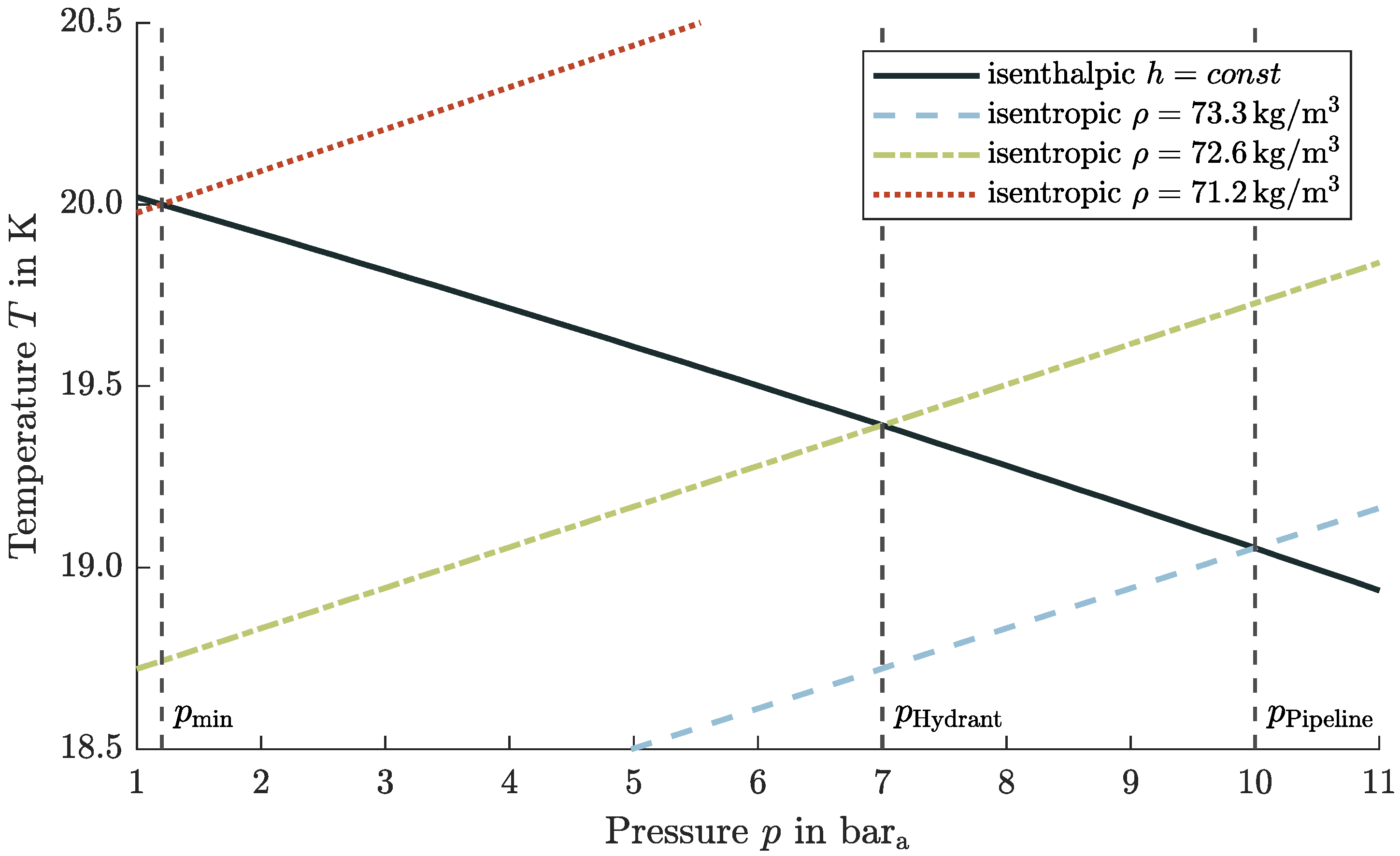
3.11. Performance Calculation Method for Subcooling of Liquid Hydrogen

To determine the power requirement of a cryogenic refrigerator/cryocooler or densification system, the following approach is chosen. The Coefficient of Performance (COP) can determine the cooling capacity of the heat exchanger [64]:
P el = Q ˙ heat COP = m ˙ · Δ h COP
The COP describes the ratio of extracted heat flow and applied electrical power and is a characteristic of the cooling system’s efficiency [64]. In the case of an ideal Carnot process, the COP is 0.056 [64]. However, the values vary depending on the cooling system (densification system) from 0.004 for a cryocooler to 0.032 for a thermodynamic venting system and Claude cycle [64]. A COP of 0.032 is therefore assumed for further considerations.

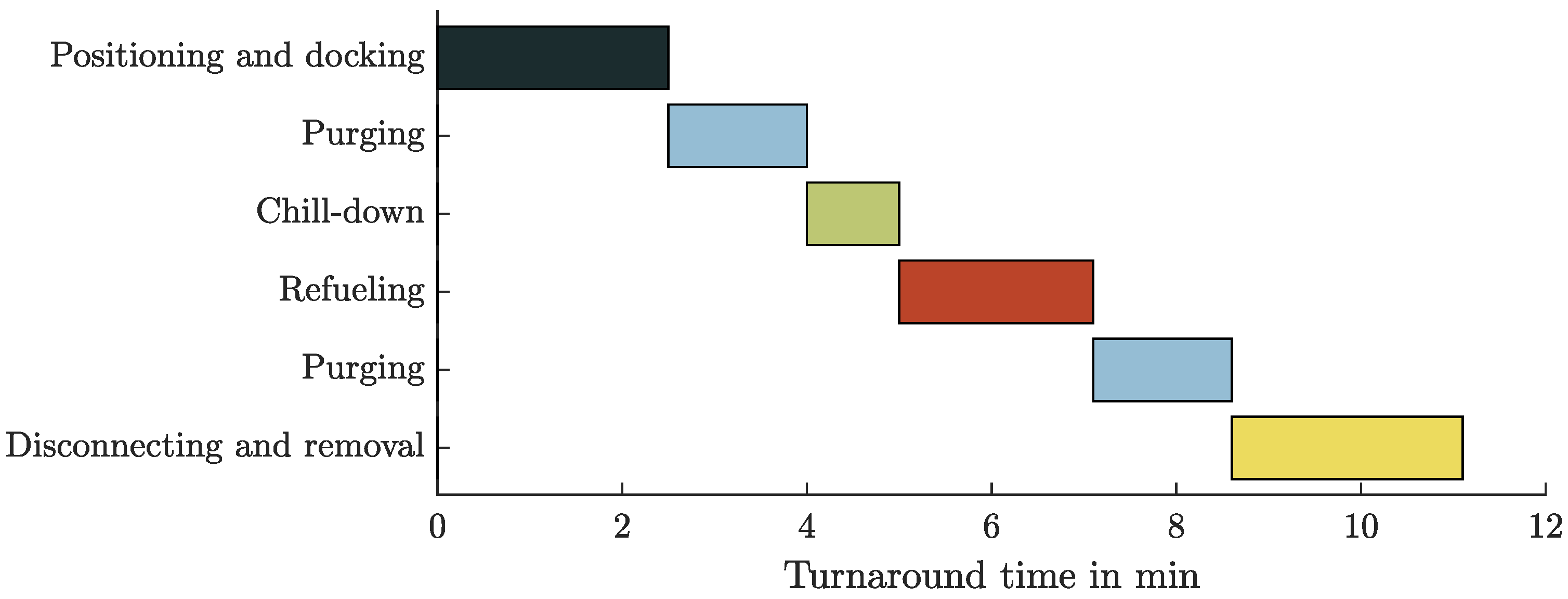
3.12. Procedure of Refueling

The refueling process of LH2 can be divided into the following steps: connecting, purging, chill-down, refueling, purging, and disconnecting. These steps are determined in the following part to establish the required duration and to define a suitable design. The results on duration are given in Section 4.1, taking into account the dependencies on other refueling steps. Thus, the equations cannot be solved separately from each other.

3.12.1. Docking Maneuver

The refueling process begins with the positioning of the ground vehicle that executes the refueling. The Jet A-1 procedure does not make sense with LH2 because the hose and pipe weigh considerably more than a Jet A-1 deck hose and can no longer be handled by one person. Moreover, manual handling of hoses with cryogenic liquids is a safety issue and demands two qualified persons [51]. Thus, manual handling poses difficult-to-perform requirements that can be significantly simplified by a (semi-)automated docking system.
The (semi-)automated automotive process (see Section 2.4.1) can also be transferred to aircraft size, where a remotely controlled boom is attached to the ground vehicle. A comparable system design could be the de-icing vehicle, which shows the implementability and feasibility.
The boom design assumes a maximum height of the aircraft adapter of 10 m. Therefore, the delivery head is 10 m, and the hose length is estimated to 20 m. The (semi-)automated process execution is expected to take an equal amount of time to the manual process at Jet A-1. Therefore, it is assumed that the docking maneuver will be carried out in 2.5 min; see Section 2.1.

3.12.2. Connecting and Purging

The purging process is an extension of the refueling time because it is not required for Jet A-1. Determining the time required for purging affects the refueling time and, consequently, the turnaround.
When connecting an LH2 disconnect, different measures are required than for Jet A-1. The reason for this is that, as described in Section 3.1, no dangerous explosive atmosphere may develop, and, in addition, no foreign gases may enter the tank and fuel system. The system’s contamination of oxygen must be less than 1 ppm [51] before transferring LH2 and only a maximum spillage of 50 mL may occur [103]. For GH2, the guidelines are not as strict because the oxygen content should be less than 1% by volume [30]. The Johnston coupling (with purging) and the clean break disconnect (without purging) are two feasible methods to fulfill these requirements, as defined in Section 3.3. For the Johnston coupling, a sequential process called vacuum purging (alternating vacuuming and pressurization with an inert gas) is used to remove foreign gases from the hose and disconnect [51]. The advantages are the reduction of the required amount of inert gas and the adequate purging of all voids and deadlegs [51]. By repeating the cycles, the desired contamination level can be achieved; see Section 3.4.
The pressurization is handled with standardized gas cylinders and cylinder bundles. Due to the higher pressure of the helium gas cylinder (300 bar [104]) or the pressure difference to the hose, helium flows out without any additional equipment. Only the pressurized gas cylinder valve needs to be opened to perform pressurization in the purging process. The pressurization system has the advantage of being a simple system. The changing of empty gas cylinders is also no problem. Using a clean break disconnect, the purging process is excluded; see Section 2.3. This method does not require inert gas, which offers an economic advantage in time and costs.
Finally, it can be concluded that a clean break disconnect would be the best solution in future through the avoidance of the purging process which has an advantage of time and costs of helium. Nevertheless, the Johnston disconnect is also considered because it is fully developed and is the simplest method to implement, given the higher readiness level and the common use for delivery trucks [44,45].

3.12.3. Chill-Down of Hose and Reduced Mass Flow

LH2 only exists at cryogenic temperatures below 20.3 K at ambient pressure which creates a high temperature difference and affects the heat transfer from the wall to the fluid. For high temperature differences, especially when cooling tank and transfer line hardware from ambient temperature, two-phase phenomena must be considered which are defined as boiling heat transfer [82]. Therefore, during the time frame of the chill-down, a two-phase flow is considered in the mathematical model. Goal of the cooling process is a vapor-free (single-phase) flow to ensure a reliable liquid mass flow. A section on the aircraft or ground vehicle will heat up and has to be chilled down; see Section 4.1. The calculation method for the required time for the chill-down is explained in Section 3.3. Potential consequences of two-phase flow are analyzed in Section 4.4.2.
In addition, temperature gradients in the material or pipe could create undesirable stresses leading to damage and fatigue failures [105]. Only a reduced mass flow can be refueled in the chill-down phase to keep the thermal stress low. However, the reduced mass flow is not included in the amount of fuel that is refueled. Sensors provide feedback on the pipe temperature before transferring regular mass flow, which should be at least below 25 K. The reason for that is the sudden temperature drop in the transition boiling [106,107], which would result in higher material stresses.
The reason for that is the sudden temperature drop in the transition boiling [106,107], which would result in higher material stresses.
The refueling process differs fundamentally from conventional Jet A-1 because of the vaporization losses. Due to the required recovery line (see Section 2.4.1), it is essential to connect two lines to the aircraft, but only one can transfer a deliverable mass flow of LH2. In contrast to the automotive application in Section 2.4.1, a coaxial pipe is not considered because the outer diameter would be too large.

3.13. Definition of GH2 Recovery Line

The vaporized H2 must be removed from the aircraft during refueling as the tank pressure should not increase significantly, which would affect the pump performance through a higher delivery pressure. In Section 3.5 the mathematical model is described.
During the chill-down phase, the maximum vaporized H2 mass flow is used as the design point for sizing the recovery line’s diameter. With this variable design point method, the theoretical consideration of complete vaporization of the reduced mass flow could be considered.
A further calculation task is whether the recovery line in the fast fill, without reduced mass flow, can remove possible proportionate vaporized amounts of H2 that occur due to environmental heat impact. A heat flow in the order of 4 W/m occurs through the Vacuum Insulated Pipe (VIP) [108,109,110,111]. In addition, the heat input to the aircraft tank is in the order of 30 W/m2 [112]. The heat flow and vaporized mass flow that occurs during the steady refueling process is therefore negligible and no design point.

3.13.1. Fueling Mass Flow of Liquid Hydrogen

The simplest comparison of H2 and Jet A-1 refueling flow rates is to set the energy flow of both to 2100 MJ/s, see Section 2.1. This is possible as a first approximation, as a flight with a comparable aircraft configuration needs the same amount of energy, assuming same efficiencies and masses. This evaluation results in an LH2 mass flow of 17.5 kg/s or a volume flow of 14,900 L/min.
In Table 1, there is a literature comparison for H2 aircraft refueling parameters. The mass flow rates tend to 20 kg/s, which is selected for the following work. In addition, the table gives an overview of the simplified Reynolds term v · d and the velocity in the hose.
Edeskuty et al. [114], and OSMA [30] describe the electric charge build-up for LH2 as no problem, which means that the Reynolds number can be higher (factor 42, see Section 2.1) than for Jet A-1. Therefore, the Space Shuttle refueling is chosen as the limit for the flow regime, expressed by the simplified Reynolds term (Section 2.4.2), because it has proven to be reliable for decades. This restriction is expressed through the simplified term and a limitation on velocity:
v · d 2.35 m 2 / s
v 15.5 m / s short pipe
v 8.0 m / s long pipe
However, the boundary conditions for the velocity are only implemented as a second precaution. The Reynolds number or the simplified term is meaningful. Due to the limitation of the flow velocity in combination with the Reynolds number, high velocities or small pipe diameters are excluded. For this reason, the velocity in a long pipe is chosen to be less than the Space Shuttle. On the other hand, the velocity for short hoses is selected according to an approximate average of Table 1.
Applying both limits results in a refueling hose with an inner diameter of 152.4 mm (6 in). In contrast to Jet A-1, this larger diameter is no problem for the handling by the ground staff as the connection in any case would be carried out (semi-)automatically, see Section 3.12.1.

3.13.2. Procedure after the Refueling

Cold LH2 remains in the refueling hose to keep the loss of LH2 as low as possible and avoid the necessity of chilling down the entire hose from the ground vehicle to the aircraft tank during each refueling process [15]. By switching valves, LH2 can be retained in the feed hose, whereby this part remains at cryogenic temperature and does not have to be cooled during the following refueling process.
This procedure is possible with both the Johnston disconnect and the clean break disconnect. For the Johnston disconnect, the purging process can be carried out through the recovery line and a suitable arrangement of valves. A small expansion tank is attached to the ground vehicle to avoid a disproportionate pressure increase in the completely filled hose due to environmental heat input and vaporization. This expansion tank represents a kind of heat reservoir and extends the time between possible refueling processes.

4. Liquid Hydrogen Refueling Process and Implications on Turnaround Times

An LH2 turnaround process has to be possible in a similar timeframe as for conventional aircraft to achieve an economical basis for hydrogen aircraft. The interfaces to the aircraft are defined first, whereby the links of the refueling conditions are determined. Thus, the dependencies and requirements can be analyzed starting from a competitive aircraft. This approach is based on a similar refueling and turnaround time, which is directly related to the DOCs and therefore the economical assessment of the aircraft. Based on safe and competitive aircraft refueling conditions, the distribution of LH2 at the airport is determined afterwards.

4.1. Results of the Refueling Procedure

The results of the refueling procedure depend on the equations of the individual refueling steps and cannot be evaluated individually without considering the complete system. However, the findings are independent of the airport infrastructure and ground refueling vehicles.
Due to the diameter, the material (stainless steel), and the pipe’s wall thickness, a reduced mass flow of 3 kg/s is defined for the chill-down segment [30]. A wall thickness of 2.5 mm [97] for a stainless-steel pipe corresponds to the load case against internal pressure of 42 bar (600 psi), same as for conventional Jet A-1 hoses [24]. Thus, a chill-down time of 40 s can be calculated according to Section 3.3, independent of the line length.
By calculating the heat flow over time, the theoretical maximum vaporization fraction of the mass flow of 1.4 kg/s Equation (43) is determined. Therefore, the design point of the recovery line is the complete vaporization of the reduced mass flow of 3 kg/s. With the assumption of a maximal Mach number of 0.5, a total pressure of 1.35 bar a in the aircraft tank results from Equation (44). The inner diameter is calculated from Equation (45) to 127.0 mm (5 in). The mass flow of 1.4 kg/s results in a Mach number of 0.22 with a total pressure of 1.25 bar a .
The evacuation and pressurization are carried out via the recovery line with an assumed length of 20 m (volume of 0.25 m3), leading to an evacuation time of 13.5 s Equation (36) and a pressurization time of 13.5 s Equation (40)—in combination for one purging cycle of approximately 30 s. For a Johnston disconnect, three repetitions (see Section 3.4) correspond to a time of 90 s each before and after refueling. For the semi-automated docking and (de-)positioning, a duration of 150 s is considered. Table 2 shows the rounded values of the individual steps.
Brewer [15] estimates the time required before refueling at 7 min and after refueling at 5 min. Compared to the calculated duration for a Johnston disconnect, this is a slight deviation, with purging as the most considerable difference.
This discrepancy to the calculated values can be explained by the fact that Brewer [15] does not specify the exact number of repetitions of vacuum purging and the purging of both lines (LH2 and GH2). This assumption significantly increases the volume to be purged, which justifies the longer time. Complete purging of the refueling hose is unnecessary as with valves only the connection adapter needs to be purged through the recovery line. For a clean break coupling, purging is unnecessary and the additional time of 3 min is omitted. This time advantage is particularly effective for small refueling quantities and short-range aircraft, since the percentage of time required for the steps before and after the actual refueling is greater.
The chill-down losses are estimated at 13.6 kg in Boeing [10] (without specifying the pipe length) and a calculation in accordance with Section 3.12.3 results in m vap l = 6.2 kg LH 2 / m for ISA+15 with Equation (46). An evaporated quantity of m vap = 12.4 kg LH2 is considered to be chill-down losses for a estimated length of 2 m to be cooled Equation (47).

4.2. Airport Distribution System for Liquid Hydrogen

Continuing the previous analysis of the refueling process required to keep the turnaround time approximately constant, the airport distribution of LH2 is also considered in the following. The results from Section 3.12 will be used to determine the overall system of the refueling process with airport distribution and ground refueling vehicles.
There are two ways of transferring the fuel from the storage facility to the aircraft tank, similar to Jet A-1, with a refueling truck or through a pipeline dispenser system. The choice of the distribution system depends on the airport’s daily fuel demand and infrastructure, and therefore no general decision can be proposed. For the techno-economic analysis, refer to Hoelzen et al. [19].
For both distribution systems, the pressure losses and pressure requirement to deliver LH2 to the aircraft tank are calculated according to Section 4.7. The aircraft tank pressure is set to 1.2 bar a . The vehicle-independent parameters, such as delivery head and hose lengths, are defined in Section 3.12.1.
In a pipeline dispenser case, the lines from hydrant to dispenser are neglected due to the short lengths. The number of valves ( K valve = 300 m 3 / h ) considered for the dispenser case is six and four for the refueling truck.
For calculating the required pressure, a static pressure of 6.5 bar a must be present at a hydrant to enable refueling with a dispenser. ISO/PAS 15594 [113] specifies a pressure of 7 bar a at the hydrant, which is similar to the calculated value and therefore used in the following investigation. A pressure of 5 bar a results for the refueling truck tank because there are fewer valves.

Refueling Tank Truck for Interim Phase

From a hardware and architectural standpoint, the simplest distribution system for aircraft refueling is by a tank truck [10]. However, this concept was not considered further in the terminal ramp area by Boeing [10] due to the physical space requirements.
Boeing [10] does not consider a refueling truck because of safety and environmental impacts, long-term costs for GH2 losses, acquisition and operating costs, and the congestion due to additional ground vehicles. Conversely, a meaningful use of refueling trucks is possible in case these negative reasons can be disproved. The argument of the costs of investment and operations required for the provision and use of refueling trucks is excluded by Boeing [10] itself since the costs would have to be ignored for a pipeline system. Congestion from the additional ground vehicles may be significant in the case of general refueling with refueling trucks. However, this argument is no longer valid if the use is intended in an interim phase or small quantities. The effects of the loss of GH2 during the venting process can be refuted by recycling GH2. Boeing [10] used a recovery line to collect the vaporized H2, but no pipeline system will be installed for the transition phase and recirculation is not possible.
Loss-free refueling requires an additional storage system, which consists of a compressor and high-pressure tanks to store GH2, helium-air and helium-GH2 mixtures for the Johnston disconnect. Without the purging process and a clean-break disconnect, the helium-air and helium-GH2 mixture tanks are not necessary. Figure 2 shows a refueling truck with the necessary structure for zero loss.
For the design of the compressor and the gaseous storage tank, the following assumptions can be made: 50 kg of H2 result in several refuelings (four times 12.4 kg) one after another. The maximal pressure of the additional storage tank is set to 350 bar. This results in a volume of approximately 2 m3 with the ideal gas equation. The compressor power depends on current storage gas tank pressure (filling level), which should be kept low. This is achieved by emptying the GH2 tank when filling the LH2 truck tank. A detailed investigation of the required power of the compressor is excluded and should be done in further studies.
For the aircraft refueling with a refueling truck, both possible variants—a pump feed system and pressure feed system—are to be considered for the delivery. Fundamentally, the variants can be distinguished in that feeding through a pressure feed system is easy to implement and does not require any significant development effort. On the other hand, a pump solution can avoid high pressures in the tank and consequently unnecessary mass having to be moved. In the following section, the properties of both variants are determined for usage in a refueling truck.

4.3. Pressurized Gas Feed System

The pressurizing gas requires a tank with a volume of approximately 1 m3 at a pressure of 700 bar for an LH2 tank volume of 70 m3 Equations (8) and (9). This system is suitable for both GH2 and helium as pressurant because the volume is almost independent of the gas used; see Section 3.2.2.
This pressurant must also be refilled during the loading process with LH2 of the truck. For the refueling of the GH2 or helium, the automotive industry’s technology and standards [41,42] can be used. An additional advantage of the pressurized gas feed system is the simplicity. Pressurization with a heat exchanger or, more precisely, a vaporizer is excluded because of the high power requirement of 510 kW Equation (10) for each refueling truck (without efficiency losses).
Due to the possibility of intermediate storage, the processes have no direct loss, which further renders Boeing’s [10] argument of significant losses invalid. Furthermore, the fuel truck has the advantage through the combination of pressurization for delivery and the compressed recirculated gas. The recirculated and compressed GH2 can be used as a pressurant for the fuel truck tank. This synergy makes the fuel truck self-sufficient to a certain extent.

4.4. Pump Feed System

With the defined mass flow of 20 kg/s and compliance with the defined similarity pump parameters, an NPSH value of 37.2 m and a rotational speed of 10,000 min−1 can be calculated, see Section 3.2.1. For the refueling truck, this indicates that the tank pressure must be 0.26 bar above the saturation line. Considering the efficiency of the LPFTP of the SSME of 0.73 [77], the pump requires a power of 148 kW; see Equation (52).
As already described, pressurization must also be applied to pump feed systems; see Section 3.2.1. The difference is the pressure level in the tank, which is much lower with a pump feed system, contrary to a pressurized gas feed system. As a result, a significantly smaller amount of pressurant is needed. A gas volume of only 0.3 m3 (Equation (9), p = 700 bar) has to be provided for the intermediate storage tank’s pressurant. Moreover, the pump case differs by a factor of p pressurized / p pump = 5 / 1.26 and only a heating power of 128 kW Equation (10) is required to maintain the pressure with the second possibility of a vaporizer. In contrast to the pressure feed system, the required energy flow for vaporization is realizable and feasible in a pump system to maintain the required pressure.
In summary, distribution at the airport is possible with a refueling truck without direct losses. This is achieved by the use of a gaseous intermediate storage tank, which collects the recirculated gases compressed by a compressor. The transfer from the fuel truck tank to the aircraft can be realized by a pump or a pressurization system. In addition, the fuel truck offers the possibility to supply even remote parking locations. Especially for a transitional phase in which the fuel types may still be spatially separated, this flexibility offers an advantage. Furthermore, the refueling truck concept must in any case be available for emergency refueling [10].

4.4.1. Dispenser Truck and Pipeline Supply for Large Quantities

The second method of aircraft refueling is to use a pipeline dispenser system. The main tasks of a dispenser truck, like for Jet A-1 [22], are to reduce the pressure from the pipeline and establish the connection between hydrant and aircraft. In principle, a pump at the storage tank pumps the fuel through underground pipes to the terminal or apron. The transfer of LH2 in the pipeline through a pressure feed system at the storage tank can be excluded immediately, as the losses are primarily due to the pressure cycle of pressurization and depressurization [11]; see Section 4.4.2.
For the calculation of the pumping capacity and the pressure provided at the storage tank, a 2000 m long pipeline with two valves ( K valve = 1300 m 3 / h ) is assumed. For reasons of redundancy, several pipelines must be introduced. Thereby, in the following consideration, one supply pipeline is designed for a mass flow of 40 kg/s, which allows two aircraft to be refueled simultaneously. The pump must provide a pressure of 10 bar a Equation (48) to compensate for friction losses for a 304.8 mm (12 in) diameter pipe to meet the hydrant’s boundary conditions ( 7 bar a ). This determination results in a speed of 11,700 min−1 and an NPSH value of 73 m, which corresponds to positive pressure to the saturated line of 0.5 bar; see Section 3.2.1. With Equation (52), the required power of 660 kw is calculated considering an efficiency of 0.73 for a mass flow of 40 kg/s. Brewer [11] assumes a differential pressure to the saturated liquid of 0.345 bar. To conclude, the values are similar and show the importance of a suitable design. The fundamental difference to a fuel truck is the handling of the vented GH2. An additional recovery pipe returns it to a recycling or liquefaction plant [10,11]. Therefore, all losses can be collected and no amount is vented to the atmosphere. A distinction is made in the different gases during refueling, which means several recovery lines to avoid a hydrogen-air mixture as a safety aspect.
As the tank position is an open variable in the aircraft design with LH2 as fuel, there is no predefined solution for the tank position [5]. The length of the line between the hydrant and the refueling vehicle will be limited to a few meters for handling reasons. This constraint means that a hydrant connection at the aircraft’s nose cannot be used for refueling a tank in the tail, as the required line becomes too long. Conversely, due to the current tank position variance, several hydrants must be installed at one parking position.
From the obtained results and the combination with the safety-relevant aspects, a dispenser can be derived, see Figure 3.
The independence from the mass of LH2 to be refueled is also advantageous for dispenser distribution. In contrast to a fuel truck, which is limited by tank volume and vehicle size, the dispenser can also refuel long-range aircraft without repeated connection and disconnection. On the other hand, the investment costs for the conversion of the airport are much higher. Due to the installation of the required pipes, the complete airport distribution system has to be rebuilt. The existing pipeline system for Jet A-1 is not usable since insulation will be necessary to keep the heat input low (see Section 4.4.2). Furthermore, the conversion would restrict flight operations or cause extensive construction work, which would lead to a further increase in costs.
Another possibility for bridging the pipeline to the aircraft is Boeing’s terminal boom fueling concept [10]. In principle, this system offers the advantage of less ground vehicles. However, this advantage also entails the disadvantage of less flexibility. Due to the boom’s design characteristics, refueling is only possible on the right, front side. Long fuel pipes in the aircraft would be heavy when the aircraft tank is not in the front, and the chill-down time would significantly increase. Therefore, this option is excluded as a possible fueling scenario. The aircraft’s refueling adapter should be located near the LH2 tank of the aircraft.
The implementation of fuel distribution of LH2 at the airport is possible. The trade-off between high investment costs for a pipeline dispenser system and the possibility of refueling large quantities or a fuel truck as the simplest system with low investment costs and the limitation of the fuel truck tank volume should be performed. A refueling truck supply can be a possible variant for a transition phase between Jet A-1 and LH2, where both fuels are needed. The refueling truck concept enables a conventional airport to also refuel with LH2 without significant modifications and costs. Furthermore, two types of possible ground refueling vehicles (dispenser and refueling truck) must be provided for refueling, depending on whether the aircraft manufacturer prescribes a purging process and the disconnect variant or not.

4.4.2. Airport Storage and Distribution Requirements

The importance of investment and operating costs, required for comparison, should be reflected, especially for the analysis of fueling distribution. The costs that would be required for the provision and use of refueling trucks are excluded by Boeing [10], as the costs of a pipeline system are ignored. This shows the difficulty of choosing a suitable system. The airport infrastructure must guarantee sufficient supply and provision of LH2 for the aircraft. The capacity of the storage tank will not be considered—refer to Hoelzen et al. [19] for a detailed consideration based on capital and operational expenditures.
The thermodynamic properties of LH2 in the airport’s storage tank are more critical for the refueling process. However, Brewer [11] ( 1.034 bar a ) and Boeing [10] ( 1.103 bar a ) set the minimum and nominal storage tank pressures, respectively, below these explosion protection regulations (see Section 3.1) in order to keep the temperature of LH2 as low as possible. This low-storage-pressure method [10,11] compromises airport safety and is not applied.
In the storage tank, the content is in thermodynamic equilibrium during phases where refueling is not performed [11]. Increasing the (minimum) pressure raises the temperature (saturated liquid line) and decreases the density, which has a negative effect on the overall design; see Section 5.1. The pressure must be increased for delivering, which is achieved through a pump or a pressurization system. The main disadvantage of a pressure feed system are the losses that occur due to the alternating pressurization and depressurization in the storage tank [11]. However, this procedure must be executed because otherwise, the fluid temperature would increase with the higher pressure due to the environmental heat impact. After depressurization, LH2 in the storage tank evaporates back to the saturated liquid line. This flash evaporation leads to losses. Brewer [11] determined a three times higher loss of a pressure feed system than a pump system. Nevertheless, the pump system’s disadvantage is the increased complexity and thus the reduced reliability and flexibility [74]. A pumping system at the storage tank for the delivery of LH2 is considered in the following because of the smaller losses. A pressurization system (by helium or vaporizer) has to increase the storage tank’s pressure through the requirement of the pump. The saturated liquid becomes subcooled, which allows the pump to deliver the LH2 as a single-phase fluid, which has the advantage of minimizing flash-off [11]. As a result of the non-thermodynamic equilibrium, the liquid in the storage tank heats up and is returned to its saturated state after the refueling process. Therefore, pump delivery has a similar effect, where losses occur due to flash evaporation. However, since the pressure difference between pure storage and pumping is much smaller than the pressure feed system, it is more economical.
In the further consideration between the pressure increase of the pump and the flow entering the tank, the properties of a real compressible fluid are essential. Downstream of the pump, an isenthalpic change of state can be considered to determine the properties of LH2. The isenthalpic flow approach can be applied in a vacuum-insulated pipe since the temperature change due to the heat input of a typical vacuum-insulated pipe of 3.5 W/m [108] with a length of 2000 m only translates into a temperature change of 0.05 K; see Equation (53). The system always remains cool by circulating the fuel in the pipeline system [10,11], which means no excessive temperature increase occurs during the non-delivery period through environmental heat. Therefore, the assumption of an isenthalpic flow through the pipeline is fulfilled.

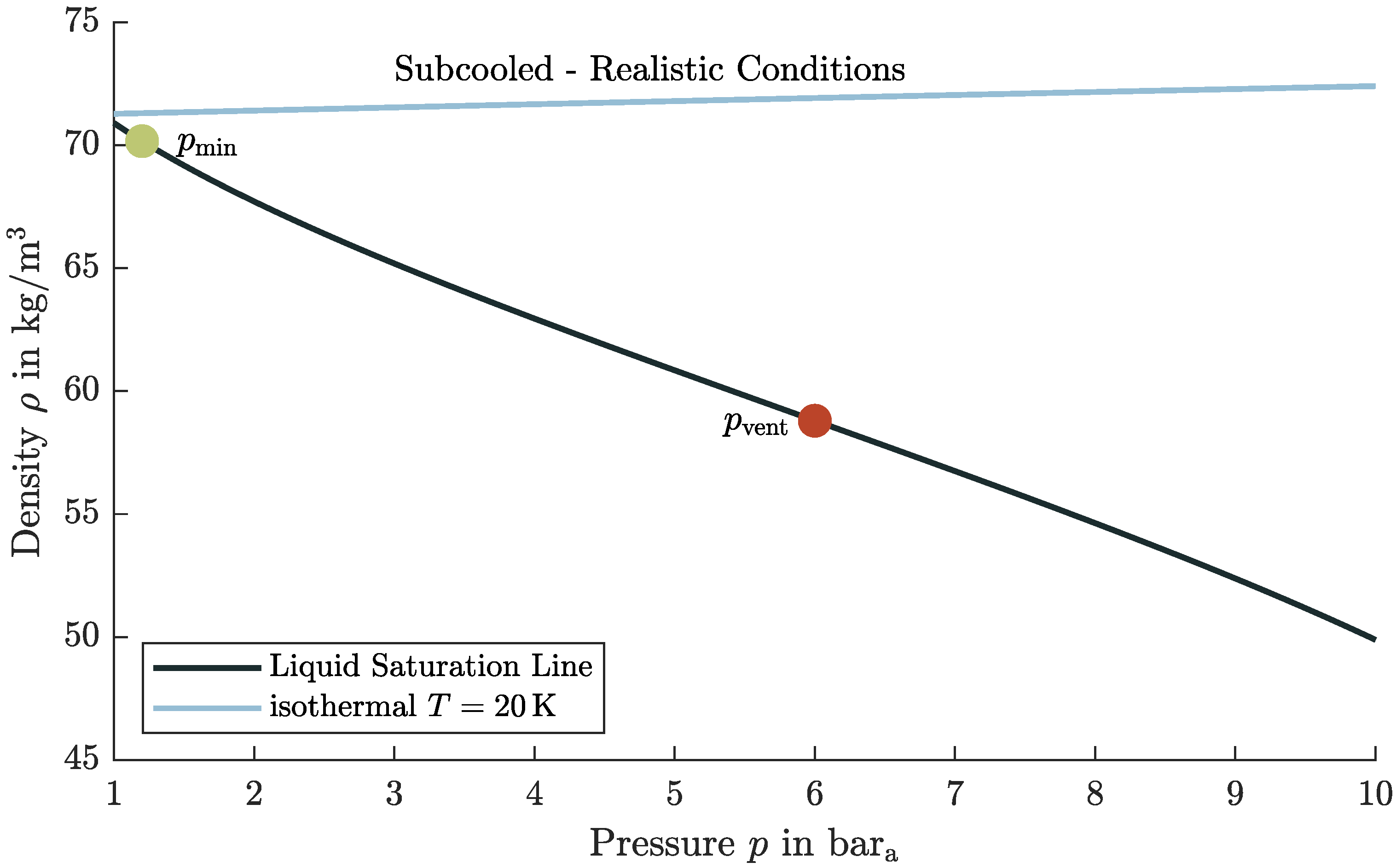
4.5. Subcooling Considerations for LH2 Refueling

In the previous considerations of the airport distribution and the flow through pipes, a single-phase flow’s essential requirement is always fulfilled (chill-down excluded). The following section highlights the reason for the necessity and inevitability of a single-phase flow.
The pressure losses due to valves and friction in the pipe express a temperature increase in an isenthalpic flow. These changes significantly affect the phase of LH2, as the friction loss is converted into internal energy. Therefore, when flowing into the aircraft tank, there must be at least a saturated liquid with a vapor content of x = 0 . Otherwise, a two-phase flow will establish, leading to a significant increase in velocity due to the phase change. Considering the isenthalpic change in state, this hypothetical reflection leads to partial vaporization of the liquid phase, which has a significantly lower density (factor 27 at 2 bar).
Due to the density change, the velocity would increase enormously, which would lead to an infringement of the introduced limitation in the velocity and simplified Reynolds term. Thus, the liquid phase’s mass flow would decrease disproportionately ( m ˙ = const . ) and lead to a considerably longer refueling process. When calculating the actual mass flow rate, considering the defined limitations, a 50% reduction in the LH2 mass flow rate of 10 kg/s would result even, with low vapor fraction of x = 0.022 , see Section 3.9. This condition must therefore be prevented under any circumstances. In addition, the vaporized H2 that is fed into the tank must be recovered, as otherwise, the pressure in the aircraft tank would rise and be reflected in the recovery line’s dimension. Relating these results to the aircraft design, the volume of the aircraft tank is determined from these tank conditions, which has a considerable influence on the mass and hence the performance of the aircraft; see Section 5.1.
In principle, there are two ways to prevent this phenomenon by maintaining a subcooled liquid. One is to increase the pressure in the system and the other is to decrease the temperature, as defined in Section 2.2. The pressure increase is limited by the burst pressure of the aircraft tank or the required pump power and cannot be increased significantly. Therefore, cooling LH2 (subcooled) is the more suitable choice. Thus, the tank’s pressure can be kept low during the refueling process so that no evaporation occurs. Figure 4 shows the isenthalpic flow due to the pressure loss of a pipeline system. Due to the conversion of energies, the temperature at the inlet to the tank rises to 20 K. In other words, LH2 must be cooled to 19 K behind the pump of the storage tank to prevent two-phase flow.
For the cryocooler, an electrical power of 13.38 MW (Equation (59); Δ T = 2.3 K ; p = 10 bar a ) for a mass flow of 20 kg/s results for the cooling of LH2. Thereby LH2 enters the aircraft tank at a temperature of 20 K with a pressure of 1.2 bar a . This cooling capacity corresponds to an additional energy input of 666 kJ / kg LH 2 . Considering the energy input of 210 MJ / kg LH 2 for the production of LH2 (electrolysis and liquefaction) [3,34,53,115,116,117,118], this additional energy input of 0.32% is reasonable, and is necessary to meet similar refueling and turnaround times.
Due to the physical properties and evaporation that could occur, the volume flow measurement is not trivial. Not all measuring devices are suitable; they must be able to cope with a two-phase flow and withstand high flow speeds and excessive rotor speed without damage [119]. The mass flow is determined with a direct measurement by a Coriolis mass flow meter [120], which has no rotating components and is therefore suitable for two-phase flows and higher speeds.

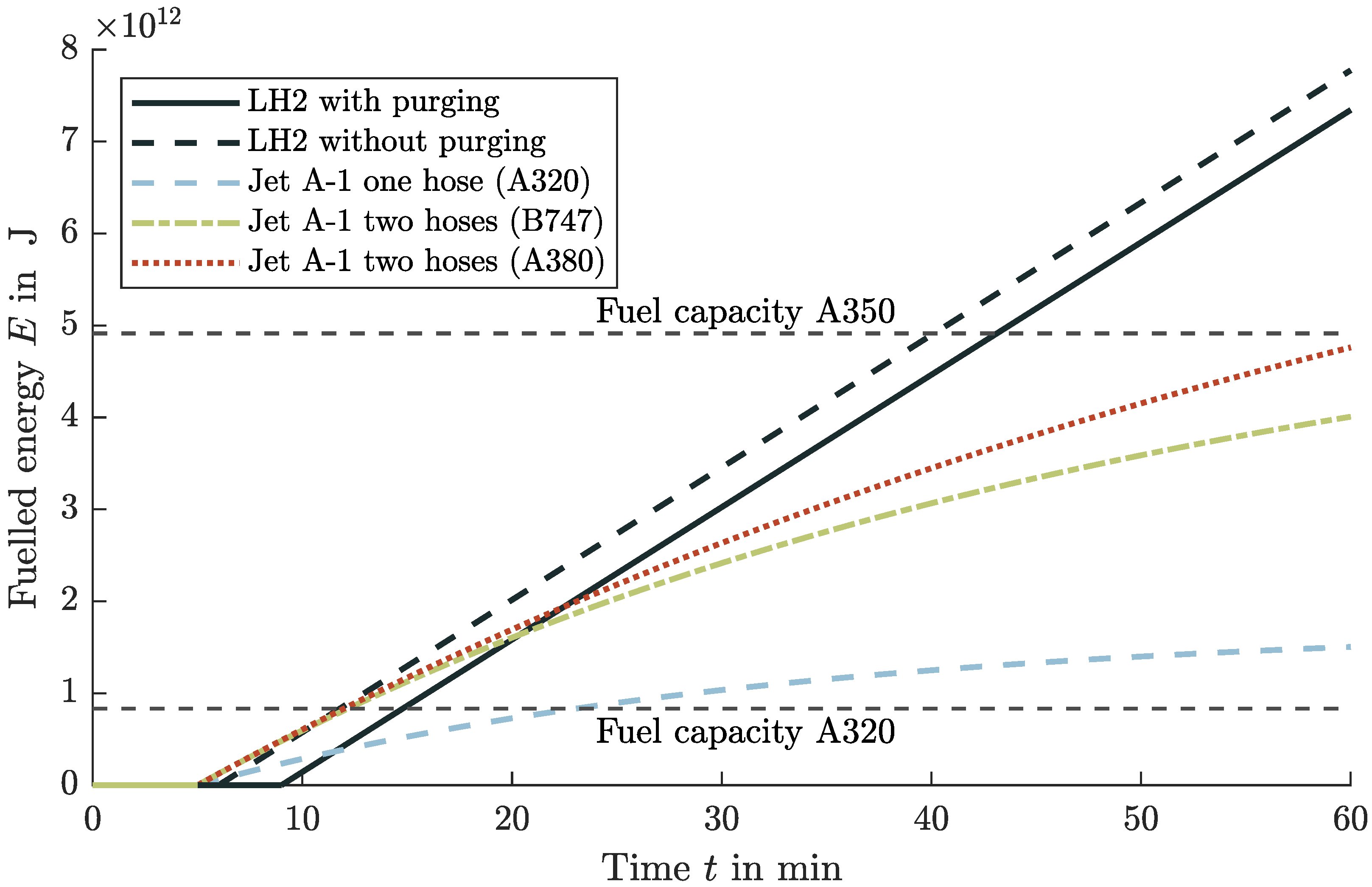
4.6. Comparison and Impacts of Liquid Hydrogen to Conventional Jet A-1 Turnarounds

After designing and analyzing the refueling conditions and procedure, the transmission by ground refueling vehicles, and the distribution at the airport, the comparison to the conventional refueling method with Jet-A1 can be performed. In this section, the refueling time for different scenarios is compared to illustrate the effects on the turnaround. The scenarios differ in the amount of refueling, especially for short-range aircraft, and in the positioning of the aircraft tanks.
The first comparison does not refer to any specific range or aircraft size. Figure 5 shows the comparison of the time required and refueled energy for the refueling process of LH2 and Jet A-1. The refueling flow for LH2 does not drop exponentially because the design considers the increasing hydrostatic pressure beforehand. When designing the delivery unit (pump feed or pressure feed system), the connection height is set equal to the highest point in the tank. Thus, the required power is constant during the refueling process because rising liquid level becomes irrelevant. This consideration results in a linear increase in the refueling quantity.
Figure 5 illustrates the entire duration of the refueling process as the necessary processes before and after the actual refueling are included by shifting the curves to the right. It can be seen that the processes in which no mass flow is delivered, i.e., cooling down the lines and any purging that may be required, take more time with LH2. Therefore, the time required by Jet A-1 is shorter for refueling small quantities. Due to the different procedures, the break-even point of the same refueling energy results after 11.5 min with one Jet A-1 hose and 20.5 min with two hoses. In comparison, in these results with purging, the refueled mass of Jet A-1 with one hose after 11.5 min corresponds to 8425 kg Jet A-1 and with two hoses after 20.5 min to a mass of 39,180 kg Jet A-1. In a refueling process with the maximum fillable volume, LH2 has a time advantage. With smaller volumes and hence shorter ranges, on the other hand, the refueling times are similar. For the use of a clean break disconnect without purging, a time duration of 3 min can be deducted from the results.
Figure 6 shows the Gantt chart for an A320-like aircraft refueling the maximum tank volume as scenario 1. The mass of LH2 can be determined by the ratio of the calorific values (factor 2.8). A time advantage of 3 min for LH2 results in comparison to refueling the equivalent energy amount of Jet A-1 with one hose. In contrast, scenario 2 compares a refueling volume for a 500 NM (926 km) mission. Due to the small volume, the advantage of LH2 is no longer present. However, the advantage in refueling time of 2 min for Jet A-1 is of no benefit since, in most cases, refueling is not on the critical path of the turnaround through parallel refueling and boarding [29,121,122].
The previous consideration of the refueling time is independent of the aircraft configuration and the position of the LH2 tank in the aircraft. In scenario 3, the comparison of the refueling time for a 1500 NM (2778 km) mission of an aircraft with the tanks mounted at the wings will be investigated. A comparable aircraft configuration can be found in Silberhorn et al. [4] for comparisons in aircraft design and sizing and volume of the tank. The comparison will be between the possibility of parallel refueling with one pod (external fuel tank) connected to feed the other pod and the possibility of sequential refueling. In sequential refueling, where the pods are filled one after another, the refueling process takes 22 min; in parallel refueling, it takes 11 min. However, in the parallel refueling process the cooling time is independent of the pipe’s length between the pods. This assumption is only valid if this connecting pipe is short or kept at cryogenic temperatures permanently. For Jet A-1, the time for refueling takes 100 min with one hose. The aircraft configuration and the location of the refueling adapters on the aircraft represent a challenging point in the refueling time. In contrast to Jet A-1, this configurable variable of tank positions and connections has a great influence on refueling time and turnaround time.

4.7. Losses and Cost Adaption Due to Refueling with Liquid Hydrogen

The losses that occur during the refueling process should be minimized. However, these losses cannot be avoided and impact the fuel costs of LH2, as additional quantities are fed that cannot be used for the flight mission. There is a differentiation of losses between the refueling variants and the refueling process, broken down and analyzed below to determine the impact of the fuel price. However, the price increase is based purely on the additional energy consumption and helium or hydrogen consumption. Quantitative investment costs are not considered, as they are strongly dependent on utilization and quantity delivered; see Hoelzen et al. [19].
The fuel price is based on an analysis of the energy required to produce the fuel by Silberhorn et al. [4], resulting in an LH2 price of 29.15 EUR/GJ. This analysis makes it possible to compare different energy sources regardless of density or calorific value. The conversion of the energy price results in a mass-related price of 3.5 EUR / kg LH 2 . Including other literature sources results in a price range for possible fuel costs of LH2 of 1.0 to 5.7 EUR / kg LH 2 [1,4,123].
As defined, LH2 requires specific production energy of about 210 MJ / kg LH 2 , which is adopted as the basis in the following cost calculation. With the fuel price of 3.5 EUR / kg LH 2 LH2 [4], the electrical energy price results in 0.0167 EUR/MJ or 0.06 EUR/kWh. Therefore, this electricity price is the origin of the further calculation of the costs that arise from electrical energy consumption. The helium required for the refueling process is assumed to have 22 EUR / kg Helium in the following cost calculation [124]. As a result, losses of LH2, helium and the consumption of electrical energy can be added proportionally to the fuel price of 3.5 EUR / kg LH 2 .
Nevertheless, it must be mentioned that the purging operation accounts for only 0.04% of the increase. The helium price has the highest uncertainty because helium is only available in a limited amount. Thus, the recycling of helium is significantly essential to establish LH2 as a fuel.
Considering only the maximum and minimum, the increases in fuel costs are represented as follows. The minimum increase includes no purging and the lowest cost for each method. The maximum growth, on the other hand, contains a purging operation. For a pipeline dispenser system, the minimum fuel price increase is 0.45% and the maximum about 1.2%. On the other hand, for a refueling truck, the minimum increase for a pump feed system is 0.54% and maximum is 4.92%. In contrast, the fuel truck with a pressure feed system has a minimum increase of 0.56% and a maximum of 13.62%. That significant increase is justified through the use of helium as pressurant gas, compared to GH2 as pressurant and a pump solution.
In conclusion, the pipeline dispenser system has the lowest operational costs, neglecting the investment costs. A refueling truck solution is therefore also reasonable if the losses are recovered by intermediate tank storage. Otherwise, the high losses are not sustainable. From these results, it can be concluded for the airport infrastructure that fuel trucks are a reasonable choice in a transition phase because the operating cost is not significantly higher, and the investment cost is considerably reduced. Conversely, if there is a sizeable daily demand, a pipeline system will be cheaper. This variety creates a trade-off between low capital cost and higher operating cost for a fuel truck system and high capital cost and low operation cost for a pipeline dispenser system. The break-even point determination is investigated in Hoelzen et al. [19].

5. Implications on Liquid Hydrogen Aircraft Design

The scientific findings from the refueling process and the thermodynamic aspects can be transferred to the overall aircraft design. The calculation of the required tank volume based on different assumptions will be discussed. The consequences for the use of fuel pumps, which have an influence on the tank and the fuel system, are also explained. The difference between a gaseous and a liquid hydrogen engine feed is worked out to determine the required performance.

5.1. Liquid Hydrogen Aircraft Tank Volume

The aircraft tank volume calculation is an essential task for aircraft design, verifying the available mass to fly a mission. Based on Equation (58) the inner volume is linear dependent on the density of LH2. Densification (subcooling of the fluid) reduces the tank volume, which has a similar snowball effect on the mass calculation [63,64]. Therefore, the analysis and estimation method is important and necessary for the aircraft design. In this analysis, however, only the internal tank volume of the aircraft is considered. The tank structure, insulation, and other parts of the outer aircraft tank design are not evaluated. Furthermore, the thermodynamic behavior of the tank contents over a flight mission is not relevant to the consideration of the preliminary design of the inner aircraft tank volume. Time-dependent, unsteady phenomena, such as thermal stratification and sloshing, are therefore not considered in this analysis.
The first method calculates the tank’s volume with the density on the saturated line, see Figure 7, with the maximum tank or venting pressure. This approach is the most conservative method because the density of LH2 is the lowest at this point. This approach of Verstraete [125] and Winnefeld et al. [126] to select the density in equilibrium at maximum tank pressure proves to be impractical. The statement that a higher tank pressure will always lead to a larger volume (lower density) is incorrect as it requires a thermodynamic equilibrium. This condition must be prevented (see Section 4.4.2, Section 5.2 and Section 5.3) and therefore has no relevance for the aircraft design.
In the second, optimistic method, the density is determined based on the minimum tank pressure and the saturated state; see Figure 7. In space systems, except for SpaceX, this calculation method is used. The loading procedure can explain this approach with the density as a function of the minimum pressure as a saturated liquid. After the tank is almost filled, the pressure is minimized, resulting in a saturated liquid in thermodynamic equilibrium through vaporization, see Section 3.4.2. In the third variant, the density is determined from the actual tank and refueling conditions, which indicates realistic conditions because all other methods are also taken into account. Conversely, this means that a subcooled liquid also belongs in this category. Due to the subcooling, LH2 is not in equilibrium and is therefore is not in a saturated state. As a result, described in Section 3.2, the density becomes a function of pressure and temperature, and LH2 must be treated as real compressible fluid. The statement that the liquid is always on the saturated line is therefore not valid. The advantage of densification (subcooling of the fluid) is to increase the density. SpaceX uses this advantage in its Falcon 9 by refueling with subcooled liquid oxygen, see Section 2.4. This effort reduces the tank volume, which has a similar positive snowball effect on the mass calculation [63,64]. Furthermore, the refueling procedure changes. In other words, the time between the end of the refueling process and take-off must be kept as short as possible to prevent the liquid from heating up.
In conclusion, it can be summarized that the choice of density for calculating the tank volume can be determined with three methods. The first two methods differ mainly in their dependence on the pressure in the tank. The third method refers to the actual tank and refueling conditions, where the additional temperature variable is also considered. In method two, which is used as a reference value, LH2 has a density of 70.15 kg / m 3 . This results in a 9.59% reduction in density compared to method one with a pressure of 3.5 bar. Compared with method three and the realistic refueling conditions, there is an increase in density of 1.45% (20 K) or 6.67% (16.3 K) results, depending on subcooled level.
When designing an aircraft using the Breguet range equation in point performance, the actual tank conditions are irrelevant, and methods one and two can determine the tank volume. In contrast, method three with realistic tank conditions requires an accurate non-equilibrium thermodynamics model during the whole flight envelope. Therefore, non-equilibrium thermodynamics are feasible only in a higher-fidelity analysis. A corresponding thermodynamic model can be found in Daigle et al. [127], Osipov et al. [57], Vietze [128] or Ring [39].

5.2. Feeding Hydrogen from the Aircraft Tank to the Power Source

The power can be generated by direct combustion in an engine or in a fuel cell to generate electrical energy. The feeding of H2 from the aircraft tank to the power source can, in principle, be accomplished in two ways. The two types of use differ primarily in the pressure level, which is 2 to 5 bar and a temperature of 290 K in the case of fuel cells [129,130] and around 50 bar and a temperature of 260 K for combustion in a jet engines [15]. However, in both variants, GH2 is fed in, which means that the stored LH2 must first be vaporized. In principle, feeding in a liquid or gaseous phase is possible in both cases. To enable a comparison of both variants, an isentropic pressure increase Equation (52) by the pump and an isobaric heat input Equation (53) for the heat exchanger by enthalpy differences (without efficiencies) can be considered in a simplified way. In the following, the feeding possibilities for a fuel cell and a combustion engine are explained and the technical feasibility or implementation is shown.

5.2.1. Fuel Cell

Two system designs are possible to meet the inlet conditions of the fuel cell. One is to directly take the gaseous phase in the ullage from the tank and deliver it. With this variant, a vaporizer is needed in the tank to keep the pressure up and constant. The second option for a fuel cell is when the pump feeds a liquid phase, which a heat exchanger then vaporizes. However, comparing the two options for feeding a fuel cell is only possible to a limited extent. With a higher tank pressure and gaseous delivery, the pressure can build up through the self-pressurization of hydrogen, which in this respect does not require any electrical power. In contrast, pump feeding requires electrical power but is characterized by a lighter tank. This circumstance means that the comparison for feeding a fuel cell can only be applied to the overall system design, including power, efficiency, and mass, and is not investigated further.

5.2.2. Combustion Engine

For the combustion of H2, two delivery options are conceivable, which depend on the order of the system components. In both variants, a low-pressure pump installed near the aircraft tank delivers LH2. The pressure head by the low-pressure pump only has to compensate for the pressure losses due to friction reaching the engine. Close to the engine, the combustion variant differs in two possible subsystems.
First, a high-pressure pump can compress the LH2 to the desired pressure level, which is then vaporized in a heat exchanger and heated to the desired inlet temperature. The advantage of this arrangement is the smart use of the waste heat from the engine jet, which is available and can be used.
In the second option, the order of the system components is reversed. First, the LH2 can be vaporized and then compressed to be injected into the combustion chamber. The advantage of this arrangement is the free positioning of the heat exchanger and high-pressure pump.
Table 3 and Table 4 illustrate the respective electrical energies and heat quantities for both variants with isentropic compression Equation (52) and isobaric heat input Equation (53). This consideration of the required performances refers to an A320-like aircraft in cruise flight with an assumed mass flow of 0.2 kg/s.
The sums of the required energies ( Δ h ) from Table 3 and Table 4 are equal. On the one hand, this realization shows that the variable is a state variable since the result is independent of the process path. On the other hand, both methods are theoretically feasible because the thermodynamic boundary conditions are met.
However, the main difference lies in the type of energy required to meet the engine’s boundary conditions. For gaseous transport, the amount of heat needed decreases significantly compared to liquid transport. In contrast, the electrical energy for compression in the pump increases to the desired pressure level. Nevertheless, considering the overall aircraft design, there is a massive difference in the possible delivery of the energy type. In the liquid transport of LH2, only a fraction of electrical energy of the total energy is required compared to the gaseous one. Most of the necessary energy is thermal energy, which is already available in the hot exhaust gas stream and unused. The generation of electrical power in the aircraft is complex, costly and reduces the engine’s efficiency.
Hence, GH2 feeding is not practical since such electrical energy quantities are not available. The existing synergies are not used by utilizing the heat in the exhaust gas jet. All in all, for the combustion of H2, a transport of LH2 by a low-pressure pump, high-pressure pump, and subsequent heat exchanger is preferable. Both variants, gaseous and liquid transport, are possible for fuel cells operating at a lower pressure level.

5.3. Realistic Tank Conditions

The investigation in Section 5.2 describes the necessity of feeding a single-phase fluid to the high-pressure pump. The avoidance of a two-phase flow can be ensured by the installed pump’s characteristic in combination with the pressure conditions at the pump inlet. However, the two pump variants (Zero-NPSH, NPSH c ) have extreme effects on the tank system, as the NPSH c pump requires a subcooled liquid in every flight condition. Figure 8 shows this behavior through a condition flight box. By re-dimensioning the pump, a NPSH value of 26 m must be present or expressed by the overpressure to the saturated line of 0.18 bar; see Section 3.2.1. The following section includes only theoretical considerations from the results of this paper and is without mathematical modeling and simulation.
After initial pressurization (isothermal), the tank condition moves closer to the limitation of the heat input (isobaric). However, this limit must not be exceeded. Otherwise, damage and pump failure could occur. This condition can only be prevented if the tank is pressurized again. This repressurization establishes a subcooled liquid ( NPSH a ) likewise. However, due to the pressure increase where a heated gas is introduced into the ullage, the liquid in the tank can heat up again, leading to further pressurization.
Hence, this effect is continuously amplified, which leads to considerable challenges in the tank design. The maximum pressure in the tank must therefore be significantly increased to be able to provide a sufficient distance to the saturated line at the end of the flight. However, when the maximum pressure increases, the tank becomes heavier, leading to aircraft performance losses.
In contrast, a Zero-NPSH pump does not require a pressurization system. The main advantage of using this pump is that it is unnecessary to know the tank conditions exactly. Furthermore, no non-equilibrium thermodynamics model would be needed. This advantage is used by Brewer [15] and Airbus [14]. This application eliminates all the problems associated with the use of an NPSH c pump. Consequently, using a Zero-NPSH pump is a progressive technology variant that makes LH2 aircraft much more economical and easier to implement in aircraft design. Problematically, a Zero-NPSH pump still has to be developed according to Airbus [14].
For the feasibility of LH2 aircraft, this problem could become a show stopper in selecting the pump. The required subsystems for an NPSH c pump, the mass estimation which has not yet been carried out, combined with the mutually amplifying pressurization process and the resulting maximum tank pressure increase have not been sufficiently researched. Disregarding the different pump technologies in principle would be grossly negligent and risky. In space research [80], Zero-NPSH pumps only require a service life of a few minutes, whereas an aircraft should operate at least for 400 to 600 flight hours until A-Check without maintenance.
Consequently, transferring research results and simplified models from space missions to performance calculation during an aircraft flight mission requires further investigation as the operating time increases significantly. Therefore, answering this question is essential because it influences the whole aircraft design and feasibility of LH2-powered aircraft, which should be performed in future studies.

6. Conclusions

The refueling process is in the focus of this paper as a potentially critical factor of LH2-powered aircraft which could significantly reduce economic efficiency. An extended turnaround caused by safety issues or a longer refueling time would reduce utilization and increase the cost of operating an aircraft. The novelty and research gap addressed in this work is to highlight the boundary conditions, calculation methods and refueling system analysis, and draw conclusions from this. It can be stated at this point that a refueling procedure with LH2 is generally feasible, compliant with the applicable safety standards and hence without negative impact on the aircraft turnaround.
The avoidance of a dangerous explosive atmosphere results from the primary explosion protection to ensure safety. The system must be designed to be permanently technically tight in the long term, preventing H2 from escaping. Furthermore, the system must have a positive gauge pressure to avoid the ambient atmosphere from entering. For these reasons, parallel refueling of LH2 with passengers on board would also be possible, just as with Jet A-1. Nevertheless, detailed risk and failure analyses are pointed out for future studies.
New LH2 refueling procedures are described and evaluated, considering the process steps connecting/disconnecting, purging, chill-down and refueling. A time comparison with Jet A-1 shows that refueling with LH2 in most cases takes less time, as different boundary conditions affect the refueling rate. A further time improvement through the eliminated necessity of the purging process would be possible with a clean break disconnect instead of a Johnston disconnect.
After the airport storage tank, it is necessary to maintain the LH2 in subcooled conditions the LH2 to avoid two-phase flows. Refueling without generating losses can be performed with either a refueling truck or a pipeline dispenser system as two possible airport infrastructures. In the case of a refueling truck, additional systems such as a compressor and extra gas storage are required. Due to the volume limitation of a refueling truck, a pipeline dispenser system would be more advisable in particular for refueling long-range aircraft.
By understanding the thermodynamic relations and properties of LH2, a novelty in this study is also to assess the implications of refueling to aircraft design. Three calculation methods have been derived to determine the required tank volume for the aircraft, which differ in the LH2 density used. This density is determined by the saturated state of maximum and minimum tank pressure, together with the actual refueling conditions (subcooled). This consideration shows the potential of using calculation methods with different fidelity levels and the advantage of subcooling for aircraft design optimization.
The delivery of LH2 from the aircraft tank to the engine requires a low-pressure pump, a high-pressure pump, and a heat exchanger to inject LH2 into the combustion chamber at the proper boundary conditions. With this fuel system architecture, only a small amount of electrical power is required for the pumps, and the waste heat from the propulsion unit can be used for vaporization. A gaseous delivery from the tank to the engine is non-practical, as compressing GH2 would require much more electrical power compared to liquid feeding.
Single-phase fluid is mandatory for feeding the high-pressure pump during a flight mission. Two methods can be seen to achieve a single-phase flow: a cavitation-free NPSH c or a Zero-NPSH pump. Especially for the cavitation-free pump, additional mass must be considered for the aircraft design to maintain the necessary conditions until the end of the flight mission. Nevertheless, the use of Zero-NPSH pumps would have a far-reaching impact on aircraft design, as no pressurization system is required. Hence, their usability must be further investigated with respect to usability. Therefore, realistic aircraft tank conditions and pump selection are essential for aircraft design and should be examined in more depth in future research. Refueling with subcooled LH2 is helpful in this context due to its lower vapor pressure and time before venting.

Author Contributions

Conceptualization, J.M., D.S., N.M. and N.D.; methodology, J.M.; investigation, J.M.; writing—original draft preparation, J.M.; writing—review and editing, J.M., D.S., N.M., N.D., J.H., T.Z. and A.S.; supervision, T.Z. and A.S. All authors have read and agreed to the published version of the manuscript.

Funding

This research received no external funding.

Institutional Review Board Statement

Not applicable.

Informed Consent Statement

Not applicable.

Data Availability Statement

Not applicable.

Conflicts of Interest

The authors declare no conflict of interest.

Nomenclature

Abbreviations
CO 2 Carbon Dioxide
COPCoefficient of Performance
DLRGerman Aerospace Center
DOCDirect Operating Cost
ETExternal Tank
EUEuropean Union
GH2Gaseous Hydrogen
H 2 Hydrogen (independent of the phase state)
LFLLower Flammability Limit
LH2Liquid Hydrogen
LHVLower Heating Value
LOXLiquid Oxygen
LPFTPLow Pressure Fuel Turbo Pump
NBPNormal Boiling Point
NPSHNet Positive Suction Head
NPSHaNet Positive Suction Head available
NPSHcNet Positive Suction Head critical
O 2 Oxygen
ppmparts per million
PtLPower to Liquid
SSMESpace Shuttle Main Engine
TRBSTechnical Rules for Operational Safety
TRGSTechnical Rules for Hazardous Substances
UFLUpper Flammability Limit
VIPVacuum Insulated Pipe
Symbols
α Refueling factor of Jet A-1/ min
Δ h v Heat of vaporization J / k g
κ Heat capacity ratio-
λ Friction factor-
μ Dynamic viscosity Pa s
ν Kinematic viscosity m 2 / s
Universal gas constant J / k g /
ρ Density k g / m 3
σ Surface tension N / m
AArea m 2
B i Biot number-
cConcentration-
c p Heat capacity at constant pressure J / k g / K
dDiameter m
gGravitational acceleration m / s 2
h v Effective Heat of vaporization J / k g
HHead m
hSpecific enthalpy J / k g
hheat-transfer coefficient W / m 2 / K
iNumber of-
kRoughness height m
kThermal conductivity W / m / K
K valve Flow coefficient of the valve m 3 / s
lLength m
L c Laplace length m
MMach number-
mMass k g
nAmount of substance
nRotational speed/ min
PPower W
pPressurebar
P r Prandtl number-
QHeat J
QVolume flow m 3 / s
qHeat flow per area W / m 2
RGas constant J / k g / K
R e Reynolds number-
SPumping speed m 3 / s
sSpecific entropy J / k g
TTemperature K
tTime s
VVolume m 3
vVelocity m / s
xVapor fraction-
Subscripts
0initial condition of gas tank
aabsolute
avgaverage
bbulk
boilboiling
ccharacteristic
convconvective
elelectrical
ggas
ggauge (difference to ambient)
iinner
lliquid
minminimum
oouter
sspecific
satsaturated
splsingle phase liquid
spvsingle phase vapor
sssuction specific
vvapor
vapvaporized
ventventing

References

  1. McKinsey & Company for the Clean Sky 2 JU and Fuel Cells and Hydrogen 2 Joint Undertaking. Hydrogen-Powered Aviation: A Fact-Based Study of Hydrogen Technology, Economics, and Climate Impact by 2050; McKinsey Company: Redwood City, CA, USA, 2020. [Google Scholar]
  2. Verstraete, D.; Hendrick, P.; Pilidis, P.; Ramsden, K. Hydrogen fuel tanks for subsonic transport aircraft. Int. J. Hydrog. Energy 2010, 35, 11085–11098. [Google Scholar] [CrossRef]
  3. Klell, M.; Eichlseder, H.; Trattner, A. Wasserstoff in der Fahrzeugtechnik: Erzeugung, Speicherung, Anwendung, 4th ed.; Springer Vieweg: Wiesbaden, Germany, 2018. [Google Scholar]
  4. Silberhorn, D.; Hartmann, J.; Dzikus, N.M.; Atanasov, G.; Zill, T.; Brand, U.; Trillos, J.C.G.; Oswald, M.; Vogt, T.; Wilken, D.; et al. The Air-Vehicle as a Complex System of Air Transport Energy Systems. In Proceedings of the AIAA AVIATION 2020 FORUM, Vitual Event, 15–19 June 2020. [Google Scholar]
  5. Silberhorn, D.; Atanasov, G.; Walther, J.N.; Zill, T. Assessment of Hydrogen Fuel Tank Integration at Aircraft Level. In Proceedings of the Deutscher Luft- und Raumfahrtkongress 2019, Darmstadt, Germany, 30 September–2 October 2019. [Google Scholar]
  6. World Economic Forum. Clean Skies for Tomorrow: Sustainable Aviation Fuels as a Pathway to Net-Zero Aviation; World Economic Forum CH-1223: Cologny/Geneva, Switzerland, 2020. [Google Scholar]
  7. AIRBUS, S.A.S. A320 Aircraft Characteristics—Airport and Maintenance Planning; Customer Services, Technical Data Support and Services; AIRBUS S.A.S.: Blagnac, France, 2020. [Google Scholar]
  8. Ahd Lf/Hf Hydrant Dispenser. 2020. Available online: https://www.rohr-spezialfahrzeuge.com/fileadmin/user_upload/Produkte/03_Flugfeldtankfahrzeuge/Datenblaetter/Produktdatenblatt_AHD_EN.pdf (accessed on 15 November 2020).
  9. Simon, V.; Weigand, B.; Gomaa, H. Dimensional Analysis for Engineers, 1st ed.; Springer: Berlin/Heidelberg, Germany, 2017. [Google Scholar]
  10. The Boeing Commercial Airplane Company. An Exploratory Study to Determine the Integrated Technological Air Tranportation Sytem Ground Requirements of Liquid-Hydrogen-Fueled Subsonic, Long-Haul Civil Air Transports; NASA CR 2699; National Aeronautics and Space Administration: Washington, DC, USA, 1976. [Google Scholar]
  11. Brewer, G.D. LH2 Airport Requirments Study; NASA CR 2700; National Aeronautics and Space Administration: Washington, DC, USA, 1976. [Google Scholar]
  12. Brewer, G.D.; Morris, R.E.; Lange, R.H.; Moore, J.W. Volume 2 Final Report: Study of the Application of Hydrogen Fuel to Long-Range Subsonic Transport Aircraft; NASA CR 132559; National Aeronautics and Space Administration: Washington, DC, USA, 1975. [Google Scholar]
  13. Sosounov, V.; Orlov, V. Experimental Turbofan Using Liquid Hydrogen and Liquid Natural Gas as Fuel. In Proceedings of the AIAA—26th Joint Propulsion Conference, Orlando, FL, USA, 16–18 July 1990. [Google Scholar]
  14. Airbus Deutschland GmbH. Liquid Hydrogen Fuelled Aircraft—System Analysis; Technical Report; Airbus Deutschland GmbH: Hamburg, Germany, 2013. [Google Scholar]
  15. Brewer, G.D. Hydrogen Aircraft Technology, 1st ed.; CRC Press: Boca Raton, FL, USA, 1991. [Google Scholar]
  16. Brewer, G.D.; Morris, R.E.; Davis, G.W.; Versaw, E.F.; Cunnington, G.R., Jr.; Riple, J.C.; Baerst, C.F.; Baerst, C.F. Study of Fuel System for LH2-Fueled Subsonic Transport Aircraft; NASA CR 145369; NASA-Langley Research Center: Hampton, Virginia, 1978; Volume 1, pp. 1–194. [Google Scholar]
  17. Brewer, G.D.; Morris, R.E.; Davis, G.W.; Versaw, E.F.; Cunnington, G.R., Jr.; Riple, J.C.; Baerst, C.F.; Baerst, C.F. Study of Fuel System for LH2-Fueled Subsonic Transport Aircraft; NASA Contractor Report 145369; NASA-Langley Research Center: Hampton, Virginia, 1978; Volume 2, pp. 195–524. [Google Scholar]
  18. Mangold, J. Economical Assessment of Hydrogen Short-Range Aircraft with the Focus on the Turnaround Procedure. Master’s Thesis, University of Stuttgart, Stuttgart, Germany, 2021. [Google Scholar]
  19. Hoelzen, J.; Flohr, M.; Silberhorn, D.; Mangold, J.; Bensmann, A.; Hanke-Rauschenbach, R. H2-powered aviation at airports—Design and economics of LH2 refueling systems. Energy Convers. Manag. X 2022, 14, 100206. [Google Scholar] [CrossRef]
  20. American Petroleum Institure. Protection against Ignitions Arising Out of Static, Lightning, and Stray Currents; API RP 2003; Health and Environmental Affairs Department, American Petroleum Institute: Washington, DC, USA, 1998. [Google Scholar]
  21. Sera, A. Jet Fuel Pipelines And Storage Require Special Operation, Maintenance Considerations. Pipeline Gas J. 2009, 236. [Google Scholar]
  22. Kazda, A.; Caves, R.E. Airport Design and Operation, 3rd ed.; Emerald Group Publishing Limited: Bingley, UK, 2015. [Google Scholar]
  23. Coordinating Research Council. Handbook of Aviation Fuel Properties; CRC Report No. 530; Coordinating Research Council: Atlanta, Georgia, 1983. [Google Scholar]
  24. Parker Hannifin Corporation. Parker Industrial Hose Gold Label® Aircraft Fueling Hose; Parker Hannifin Corporation: Wickliffe, Ohio, 2013. [Google Scholar]
  25. Eaton Aerospace Group. Carter® Underwing Refueling Nozzle Model 60427; Eaton Aerospace Group: Irvine, CA, USA, 2013. [Google Scholar]
  26. Bundesanstalt für Arbeitsschutz und Arbeitsmedizin (BAuA). Gefährdungsbeurteilung Bei Physischer Belastung—Die neuen Leitmerkmalmethoden (LMM); Bundesanstalt für Arbeitsschutz und Arbeitsmedizin (BAuA): Dortmund, Germany, 2019. [Google Scholar]
  27. Horstmeier, T.; de Haan, F. Influence of ground handling on turn round time of new large aircraft. Aircr. Eng. Aerosp. Technol. 2001, 73, 266–271. [Google Scholar] [CrossRef]
  28. Schmidt, M. Ground-Operational Assessment of Novel Aircraft Cabin Configurations. Ph.D. Thesis, Technical University of Munich, Munich, Germany, 2018. [Google Scholar]
  29. Sanz de Vicente, S. Ground Handling Simulation with CAST. Master’s Thesis, Hamburg University of Applied Sciences, Hamburg, Germany, 2010. [Google Scholar]
  30. Office of Safety and Mission Assurance. Safety Standard for Hydrogen and Hydrogen Systems; NASA Technical Memorandum NSS 1740.16; Office of Safety and Mission Assurance: Washington, DC, USA, 1997. [Google Scholar]
  31. Sutton, G.P.; Biblarz, O. Rocket Propulsion Elements, 7th ed.; John Wiley & Sons: Hoboken, NJ, USA, 2001. [Google Scholar]
  32. Huzel, D.K.; Huang, D.H. Design of Liquid Propellant Rocket Engines; NASA Special Publication 125; National Aeronautics and Space Administration: Washington, DC, USA, 1967. [Google Scholar]
  33. Leachman, J.W.; Jacobsen, R.T.; Lemmon, E.W.; Penoncello, S.G. Thermodynamic Properties of Cryogenic Fluids, 2nd ed.; International Cryogenics Monograph Series; Springer: Cham, Switzerland, 2017. [Google Scholar]
  34. Peschka, W. Flüssiger Wasserstoff als Energieträger, 1st ed.; Springer: Vienna, Austria, 1984. [Google Scholar]
  35. Brechna, H.; Tuttle, W.A.; Stewart, R.G.; Jensen, J.E.; Commission, U.S.A.E.; Laboratory, B.N. Brookhaven National Laboratory Selected Cryogenic Data Notebook; Brookhaven National Laboratory: Upton, NY, USA, 1980. [Google Scholar]
  36. Lemmon, E.W.; Bell, I.H.; Huber, M.L.; McLinden, M.O. NIST Standard Reference Database 23: Reference Fluid Thermodynamic and Transport Properties-REFPROP; Version 10.0; National Institute of Standards and Technology: Gaithersburg, MD, USA, 2018. [Google Scholar]
  37. Bostock, T.D.; Scurlock, R.G. Low-Loss Storage and Handling of Cryogenic Liquids: The Application of Cryogenic Fluid Dynamics, 2nd ed.; International Cryogenics Monograph Series; Springer: Cham, Switzerland, 2019. [Google Scholar]
  38. Baehr, H.D.; Kabelac, S. Thermodynamik: Grundlagen und technische Anwendungen, 16th ed.; Springer Vieweg: Berlin/Heidelberg, Germany, 2016. [Google Scholar]
  39. Ring, E. Rocket Propellant and Pressurization Systems, 1st ed.; Prentice-Hall, Inc.: Englwood Cliffs, NJ, USA, 1964. [Google Scholar]
  40. Stroman, R.O.; Schuette, M.W.; Swider-Lyons, K.; Rodgers, J.A.; Edwards, D.J. Liquid hydrogen fuel system design and demonstration in a small long endurance air vehicle. Int. J. Hydrog. Energy 2014, 39, 11279–11290. [Google Scholar] [CrossRef]
  41. SAE International. Fueling Protocols for Light Duty Gaseous Hydrogen Surface Vehicles; SAE International: Warrendale, PA, USA, 2020. [Google Scholar]
  42. SAE International. Compressed Hydrogen Surface Vehicle Fueling Connection Devices; SAE International: Warrendale, PA, USA, 2015. [Google Scholar]
  43. Bain, A. NASA space program experience in hydrogen transportation and handling. Int. J. Hydrog. Energy 1976, 1, 173–188. [Google Scholar] [CrossRef]
  44. Gerstl, P. Solutions for the LH2 Supply Chain. In Proceedings of the International Hydrogen Forum 2019, PyeongChang, Korea, 9 May 2019. [Google Scholar]
  45. Tamhankar, S. Terminal Operations for Tube Trailer and Liquid Tanker Filling: Status, Challenges and R & D Needs. In Proceedings of the DOE Hydrogen Transmission and Distribution Workshop, Golden, Colorado, 25–26 February 2014. [Google Scholar]
  46. Siegel, E. Humanity Is Thoughtlessly Wasting An Essential, Non-Renewable Resource: Helium. Available online: https://www.forbes.com/sites/startswithabang/2019/05/24/humanity-is-thoughtlessly-wasting-an-essential-non-renewable-resource-helium/?sh=3492c76829f8 (accessed on 1 October 2021).
  47. Stuck, D.E. Liquid Rocket Disconnects, Couplings, Fittings, Fixed Joints, and Seals; NASA Special Publication 8119; National Aeronautics and Space Administration: Cleveland, OH, USA, 1976. [Google Scholar]
  48. Stewart, W.F. Refueling Considerations For Liquid-Hydrogen Fueled Vehicles; Los Alamos National Lab.: Los Alamos, NM, USA, 1984. [Google Scholar]
  49. Hettinger, W.; Michel, F.; Ott, P.; Theissen, F. Refueling equipment for liquid hydrogen vehicles. Int. J. Hydrog. Energy 1998, 23, 943–947. [Google Scholar] [CrossRef]
  50. Linde, A.G. Linde Kupplung und Betankungssystem: Leistung und Meßergebnisse. 2003. Available online: http://www.eihp.org/public/Reports/Final_Report/Sub-Task_Reports/ST3.3/EIHP-Beitrag%20Linde%20Kuppl.pdf (accessed on 20 December 2020).
  51. NASA Lewis Research Center. Hydrogen Safety Manuel; NASA Technical Memorandum X-5245; National Aeronautics and Space Administration: Washingtion, DC, USA, 1968. [Google Scholar]
  52. Pehr, K.; Sauermann, P.; Traeger, O.; Bracha, M. Liquid hydrogen for motor vehicles—The world’s first public LH2 filling station. Int. J. Hydrog. Energy 2001, 26, 777–782. [Google Scholar] [CrossRef]
  53. Peschka, W. Liquid Hydrogen Fuel of the Future, 1st ed.; Springer: Vienna, Austra, 1992. [Google Scholar] [CrossRef]
  54. Wolf, J. Liquid hydrogen technology for vehicles. In Handbook of Fuel Cells; John Wiley & Sons: Hoboken, NJ, USA, 2010. [Google Scholar]
  55. Arnold, G.; Wolf, J. Liquid Hydrogen for Automotive Application Next Generation Fuel for FC and ICE Vehicles. TEION KOGAKU (J. Cryog. Supercond. Soc. Jpn.) 2005, 40, 221–230. [Google Scholar] [CrossRef] [Green Version]
  56. Wetzel, F.J. Improved handling of liquid hydrogen at filling stations: Review of six years’ experience. Int. J. Hydrog. Energy 1998, 23, 339–348. [Google Scholar] [CrossRef]
  57. Osipov, V.V.; Daigle, M.J.; Muratov, C.B.; Foygel, M.; Smelyanskiy, V.N.; Watson, M.D. Dynamical Model of Rocket Propellant Loading with Liquid Hydrogen. J. Spacecr. Rocket. 2011, 48, 987–998. [Google Scholar] [CrossRef] [Green Version]
  58. Space Program Operations Contract. Shuttle Crew Operations Manuel. United Space Alliance. 2008. Available online: https://www.nasa.gov/centers/johnson/pdf/390651main_shuttle_crew_operations_manual.pdf (accessed on 20 January 2021).
  59. Nguyen, K.; Knowles, T.E.; Greene, W.D.; Tomsik, T.M. Propellant Densification for Launch Vehicles: Simulation and Testing. In Proceedings of the 38th AIAA/ASME/SAE/ASEE Joint Propulsion Conference & Exhibit, Indianapolis, Indiana, 7–10 July 2002. [Google Scholar]
  60. Foust, J. NASA Approves “Load-and-Go” Fueling for SpaceX Commercial Crew Launches. Available online: https://spacenews.com/nasa-approves-load-and-go-fueling-for-spacex-commercial-crew-launches/ (accessed on 11 January 2021).
  61. Notardonato, W.U.; Baik, J.H.; McIntosh, G.E. Operational Testing of Densified Hydrogen Using G-M Refrigeration. AIP Conf. Proc. 2004, 710, 64–74. [Google Scholar]
  62. Fernholz, T. The “Super Chill” Reason SpaceX Keeps Aborting Launches. Available online: https://qz.com/627430/the-super-chill-reason-spacex-keeps-aborting-launches/ (accessed on 11 January 2021).
  63. Wilken, J.; Scelzo, M.T.; Peveroni, L. System Study of Slush Propellants for Future European Launch Vehicles; Space Propulsion 2018. Available online: https://elib.dlr.de/120361/1/039_WILKEN_update.pdf (accessed on 15 February 2021).
  64. Baik, J.H.; T-Raissi, A. R & D processes for increasing density of cryogenic propellants at FSEC. Cryogenics 2004, 44, 451–458. [Google Scholar]
  65. Space Is Kind Of Cool. Why the Falcon 9 Uses Subcooled Liquid Oxygen. Available online: https://www.youtube.com/watch?v=gHwZk_qEeAY (accessed on 12 January 2021).
  66. Huzel, D.K.; Huang, D.H. Modern Engineering for Design of Liquid-Propellant Rocket Engines; AIAA: Washington, DC, USA, 1992. [Google Scholar]
  67. Richtlinie 2014/34/EU des Europäischen Parlaments und des Rates vom 26. Februar 2014 zur Harmonisierung der Rechtsvorschriften der Mitgliedstaaten für Geräte und Schutzsysteme zur bestimmungsgemäßen Verwendung in explosionsgefährdeten Bereichen (Neufassung). Available online: https://eur-lex.europa.eu/legal-content/DE/ALL/?uri=celex%3A32014L0034 (accessed on 12 November 2020).
  68. Richtlinie 1999/92/EG des Europäischen Parlaments und des Rates vom 16. Dezember 1999 über Mindestvorschriften zur Verbesserung des Gesundheitsschutzes und der Sicherheit der Arbeitnehmer, die Durch Explosionsfähige Atmosphären Gefährdet Werden Können (Fünfzehnte Einzelrichtlinie im Sinne von Artikel 16 Absatz 1 der Richtlinie 89/391/EWG). Available online: https://eur-lex.europa.eu/legal-content/DE/ALL/?uri=CELEX:31999L0092 (accessed on 12 November 2020).
  69. Verordnung über Sicherheit und Gesundheitsschutz bei der Verwendung von Arbeitsmitteln (Betriebssicherheitsverordnung—BetrSichV). 2015. Available online: https://www.gesetze-im-internet.de/betrsichv_2015/BetrSichV.pdf (accessed on 12 November 2020).
  70. Verordnung zum Schutz vor Gefahrstoffen (Gefahrstoffverordnung—GefStoffV). 2010. Available online: https://www.gesetze-im-internet.de/gefstoffv_2010/GefStoffV.pdf (accessed on 12 November 2020).
  71. Technische Regeln für Betriebssicherheit/Gefahrstoffe TRBS 2152 Teil 2/TRGS 722 Vermeidung oder Einschränkung Gefährlicher Explosionsfähiger Atmosphäre. 2012. Available online: https://www.baua.de/DE/Angebote/Rechtstexte-und-Technische-Regeln/Regelwerk/TRGS/pdf/TRGS-722.pdf?__blob=publicationFile&v=3 (accessed on 24 November 2020).
  72. Technische Regeln für Gefahrstoffe TRGS 720 Gefährliche explosionsfähige Gemische—Allgemeines. 2020. Available online: https://www.baua.de/DE/Angebote/Rechtstexte-und-Technische-Regeln/Regelwerk/TRGS/pdf/TRGS-720.pdf?__blob=publicationFile&v=5 (accessed on 14 October 2020).
  73. Technische Regeln für Betriebssicherheit/ Gefahrstoffe TRBS 2151 Teil 1/ TRGS 721 Gefährliche explosionsfähige Atmosphäre—Beurteilung der Explosionsgefährdung. 2006. Available online: https://www.baua.de/DE/Angebote/Rechtstexte-und-Technische-Regeln/Regelwerk/TRGS/pdf/TRGS-721.pdf?__blob=publicationFile&v=6 (accessed on 1 October 2020).
  74. Jallais, S. Pre-Normative Research for Safe use of Liquid HYdrogen (PRESLHY); Fuel Cells and Hydrogen Joint Undertaking. 2018. Available online: https://www.hysafe.info/wp-content/uploads/sites/3/2018/09/PRESLHY-D2.3-LH2-Installation-description.pdf (accessed on 23 January 2021).
  75. Gülich, J.F. Kreiselpumpen: Handbuch für Entwicklung, Anlagenplanung und Betrieb, 4th ed.; Springer: Berlin/Heidelberg, Germany, 2013. [Google Scholar]
  76. Sobin, A.J.; Bissell, W.R. Turbopump Systems For Liquid Rocket Engines; NASA Special Publication 8107; National Aeronautics and Space Administration: Cleveland, OH, USA, 1974. [Google Scholar]
  77. Rocketdyne. Space Shuttle Main Engine Orientation. 1998. Available online: http://large.stanford.edu/courses/2011/ph240/nguyen1/docs/SSME_PRESENTATION.pdf (accessed on 5 December 2020).
  78. DiStefano, J.F.; Caine, G.H. Cavitation Characteristics of Tank-Mounted Cryogenuc Pumps and Their Predicted Performance Unter Reduced Gravity; Advances in Cryogenic Engineering; Timmerhaus, D.K., Ed.; Springer: Boston, MA, USA, 1961; Volume 7. [Google Scholar]
  79. Caine, G.; Schafer, L.; Burgeson, D. Pumping of Liquid Hydrogen; Advances in Cryogenic Engineering; Timmerhaus, D.K., Ed.; Springer: Boston, MA, USA, 1958; Volume 4. [Google Scholar]
  80. Stinson, H.P.; Strickland, R.J. Experimental Findings from Zero-Tank Net Positive Suction Head Operation of the J-2 Hydrogen Pump; NASA Technical Note D-6824; National Aeronautics and Space Administration: Washington, DC, USA, 1972. [Google Scholar]
  81. Lockheed-Georgia Company. Main Propellant Tank Pressurization System Study and Test Program—Design Handbook; Final Report ER-5296; Contract AF 04(611)-6087; Lockheed-Georgia Company: Marietta, Georgia, USA, 1961; Volume 3. [Google Scholar]
  82. Barron, R.F.; Nellis, G.F. Cryogenic Heat Transfer, 2nd ed.; CRC Press: Boca Raton, FL, USA, 2016. [Google Scholar]
  83. Wang, L.; Li, Y.; Zhang, F.; Xie, F.; Ma, Y. Correlations for calculating heat transfer of hydrogen pool boiling. Int. J. Hydrog. Energy 2016, 41, 17118–17131. [Google Scholar] [CrossRef]
  84. Brentari, E.G.; Giarratano, P.J.; Smith, R.V. Boiling Heat Transfer for Oxygen, Nitrogen, Hydrogen, and Helium; National Bureau of Standards Technical Note 316; US National Bureau of Standards: Gaithersburg, MD, USA, 1965. [Google Scholar]
  85. Giarratano, P.J.; Smith, R.V. Comparative study of forced convection boiling heat transfer correlations for cryogenic fluids. In Proceedings of the Cryogenic Engineering Conference, Cryogenic Engineering Conference at Rice University, Houston, TX, USA, 23–25 August 1965. [Google Scholar]
  86. Steiner, D.; Taborek, J. Flow Boiling Heat Transfer in Vertical Tubes Correlated by an Asymptotic Model. Heat Transf. Eng. 1992, 13, 43–69. [Google Scholar] [CrossRef]
  87. Brennan, J.A.; Brentari, E.G.; Smith, R.V.; Steward, W.G. Cooldown of Cryogenic Transfer Lines; NASA Contractor Report 81338; Cryogenics Division, NBS Institute for Materials Research: Boulder, CO, USA, 1966. [Google Scholar]
  88. Hendricks, R.C.; Graham, R.W.; Hsu, Y.Y.; Friedman, R. Experimental Heat Transfer and Pressure Drop of Liquid Hydrogen Flowing through a Heated Tube; NASA Technical Note D-765; US National Bureau of Standards: Gaithersburg, MD, USA, 1961. [Google Scholar]
  89. Zuber, N. Hydrodynamic Aspects of Boiling Heat Transfer. Ph.D. Thesis, University of California, Los Angeles, CA, USA, 1959. [Google Scholar]
  90. Verein Deutscher Ingenieure. VDI-Wärmeatlas, 11th ed.; Springer: Berlin/Heidelberg, Germany, 2013. [Google Scholar]
  91. Lienhard, J.; Witte, L. An Historical Review of the Hydrodynamic Theory of Boiling. Rev. Chem. Eng. 1985, 3, 187–280. [Google Scholar] [CrossRef]
  92. Kida, M.; Kikuchci, Y.; Takahashi, O.; Michiyoshi, I. Pool-Boiling Heat Transfer in Liquid Nitrogen. J. Nucl. Sci. Technol. 1981, 18, 501–513. [Google Scholar] [CrossRef]
  93. Klell, M. Storage of Hydrogen in the Pure Form. In Handbook of Hydrogen Storage; Hirscher, M., Ed.; John Wiley & Sons: Weinheim, Germany, 2010. [Google Scholar]
  94. Marquardt, E.D.; Le, J.P.; Radebaugh, R. Cryogenic Material Properties Database. In Proceedings of the 11th International Cryocooler Conference, Keystone, CO, USA, 20–22 June 2000. [Google Scholar]
  95. Steward, W.G.; Smith, R.V.; Brennan, J.A. Cooldown transients in cryogenic transfer lines. In Advances in Cryogenic Engineering; Timmerhaus, K.D., Ed.; Springer: Berlin/Heidelberg, Germany, 1969; Volume 15. [Google Scholar]
  96. Rame, E.; Hartwig, J.W.; McQuillen, J.B. Flow Visualization of Liquid Hydrogen Line Chill Down Tests. In Proceedings of the 52nd Aerospace Sciences Meeting, National Harbor, MD, USA, 13–17 January 2014. [Google Scholar]
  97. Arbeitsgemeinschaft Druckbehälter. Zylinder- und Kugelschalen unter Innerem Überdruck AD 2000-Merkblatt B 1:2000-10. 2000. Available online: https://www.beuth.de/de/technische-regel/ad-2000-merkblatt-b-1/39490160 (accessed on 22 March 2021).
  98. Jousten, K. Handbuch Vakuumtechnik, 12th ed.; Springer: Wiesbaden, Germany, 2018. [Google Scholar]
  99. Pfeiffer Vacuum GmbH. HEPTADRY™, Die Trockene Schraubenpumpe. 2016. Available online: https://www.pfeiffer-vacuum.com/filepool/file/literature/broschuere-schraubenpumpen-heptadry.pdf?referer=2686&request_locale=de_DE (accessed on 14 December 2021).
  100. Oertel, H.; Böhle, M.; Reviol, T. Strömungsmechanik: Für Ingenieure und Naturwissenschaftler; Springer: Wiesbaden, Germany, 2015. [Google Scholar]
  101. Surek, D.; Stempin, S. Angewandte Strömungsmechanik, 1st ed.; Vieweg+Teubner: Wiesbaden, Germany, 2007. [Google Scholar]
  102. Erhard GmbH & Co. KG. Datenblatt ERHARD RKV Ringkolbenventile; Erhard GmbH & Co. KG: Heidenheim, Germany, 2019; Available online: https://www.erhard.de/produkte/kategorien/sicherheits-und-regelventile/ringkolbenventile/rkv-ringkolbenventil-dn100-300-pn40-160/?no_cache=1&tx_comatecdownloads_pi1%5Bid%5D=914&tx_comatecdownloads_pi1%5Baction%5D=downloadFile&tx_comatecdownloads_pi1%5Bcontroller%5D=Download (accessed on 22 March 2021).
  103. Technische Regeln für Betriebssicherheit/Gefahrstoffe TRBS 3151/TRGS 751 Vermeidung von Brand, Explosions- und Druckgefährdungen an Tankstellen und Gasfüllanlagen zur Befüllung von Landfahrzeugen. 2020. Available online: https://www.baua.de/DE/Angebote/Rechtstexte-und-Technische-Regeln/Regelwerk/TRBS/pdf/TRBS-3151.pdf?__blob=publicationFile (accessed on 1 October 2020).
  104. Linde GmbH. Helium 5.0 Produktdatenblatt. 2019. Available online: https://produkte.linde-gase.de/db_neu/helium_5.0.pdf (accessed on 28 November 2020).
  105. Novak, J.K. Cooldown flow rate limits imposed by thermal stresses in liquid hydrogen or nitrogen pipelines. In Advances in Cryogenic Engineering; Timmerhaus, K.D., Ed.; Springer: Berlin/Heidelberg, Germany, 1969; Volume 15. [Google Scholar]
  106. Yuan, K.; Ji, Y.; Chung, J. Cryogenic chilldown process under low flow rates. Int. J. Heat Mass Transf. 2007, 50, 4011–4022. [Google Scholar] [CrossRef]
  107. Hartwig, J.; Hu, H.; Styborski, J.; Chung, J. Comparison of cryogenic flow boiling in liquid nitrogen and liquid hydrogen chilldown experiments. Int. J. Heat Mass Transf. 2015, 88, 662–673. [Google Scholar] [CrossRef]
  108. Demaco Holland, B.V. Product Sheet: Vacuum Insulated Piping. 2021. Available online: https://d86wdzef8iurf.cloudfront.net/wp-content/uploads/2021/01/EN-VI-Piping_hq-02-2018-1.pdf (accessed on 13 January 2021).
  109. Demaco Holland, B.V. Product Sheet: Vacuum Insulated Flexible. 2021. Available online: https://d86wdzef8iurf.cloudfront.net/wp-content/uploads/2021/02/VI-Flex-English-28-07-2016-2-1.pdf (accessed on 13 January 2021).
  110. Fesmire, J.; Augustnynowicz, S. Thermal Performance of Cryogenic Piping Multilayer Insulation in Actual Field Installations. Cryogenics 2002, 2022. Available online: https://ntrs.nasa.gov/citations/20020039045 (accessed on 25 January 2021).
  111. Jones, L.; Wuschke, C.; Fahidy, T. Model of a cryogenic liquid-hydrogen pipeline for an airport ground distribution system. Int. J. Hydrog. Energy 1983, 8, 623–630. [Google Scholar] [CrossRef]
  112. Millis, M.G.; Tornabene, R.T.; Jurns, J.M.; Guynn, M.D.; Tomsik, T.M.; Overbe, T.J.V. Hydrogen Fuel System Design Trades for High-Altitude Long-Endurance Remotely-Operated Aircraft; NASA Technical Memorandum 2009-215521; National Aeronautics and Space Administration: Cleveland, OH, USA, 2009. [Google Scholar]
  113. ISO/PAS 15594:2004(E); Airport Hydrogen Fuelling Facility Operations. International Organization for Standardization: Geneva, Switzerland, 2004.
  114. Edeskuty, F.J.; Stewart, W.F. Safety in the Handling of Cryogenic Fluid; Springer: New York, NY, USA, 1996. [Google Scholar]
  115. Lin, C.S.; Van Dresar, N.T.; Hasan, M.M. Pressure Control Analysis of Cryogenic Storage Systems. J. Propuls. Power 2004, 20, 480–485. [Google Scholar] [CrossRef] [Green Version]
  116. Stolzenburg, K.; Berstad, D.; Decker, L.; Elliott, A.; Haberstroh, C.; Hatto, C.; Klaus, M.; Mortimer, N.; Mubbala, R.; Mwabonje, O.; et al. Efficient Liquefaction of Hydrogen: Results of the IDEALHY Project. In Proceedings of the XXth Energie—Symposium, Stralsund, Germany, 7–9 November 2013. [Google Scholar]
  117. Cardella, U.; Decker, L.; Klein, H. Roadmap to economically viable hydrogen liquefaction. Int. J. Hydrog. Energy 2017, 42, 13329–13338. [Google Scholar] [CrossRef]
  118. Burgunder, A.; Martinez, A.; Tamhankar, S. Current Status of Hydrogen Liquefaction Costs. In DOE Hydrogen and Fuel Cells Program Record; Department of Energy: Washington, DC, USA, 2019. Available online: https://www.hydrogen.energy.gov/pdfs/19001_hydrogen_liquefaction_costs.pdf (accessed on 4 January 2021).
  119. Hord, J. Selected Topics on Hydrogen Fuel; National Bureau of Standards NBSIR 75-803; National Bureau of Standards: Boulder, CO, USA, 1975. [Google Scholar]
  120. Tränkler, H.R.; Reindl, L.M. Sensortechnik: Handbuch für Praxis und Wissenschaft, 2nd ed.; Springer Vieweg: Berlin/Heidelberg, Germany, 2014. [Google Scholar]
  121. Evler, J.; Asadi, E.; Preis, H.; Fricke, H. Stochastic Control of Turnarounds at HUB-Airports. In Proceedings of the Eighth SESAR Innovation Days, Salzburg, Austria, 3–7 December 2018. [Google Scholar]
  122. Fricke, H.; Schultz, M. Improving Aircraft Turn Around Reliability. In Proceedings of the ICRAT 3rd International Conference on Research and Air Transportation, Fairfax, CA, USA, 1–4 June 2008. [Google Scholar]
  123. Collins, L. A Wake-Up Call on Green Hydrogen: The Amount of Wind and Solar Needed is Immense. Available online: https://www.rechargenews.com/transition/a-wake-up-call-on-green-hydrogen-the-amount-of-wind-and-solar-needed-is-immense/2-1-776481 (accessed on 16 March 2021).
  124. U.S. Geological Survey. Mineral Commodity Summaries 2020; U.S. Geological Survey: Reston, VA, USA, 2020. [Google Scholar]
  125. Verstraete, D. The Potential of Liquid Hydrogen for Long Range Aircraft Propulsion. Ph.D. Thesis, Cranfield Unversity, Cranfield, UK, 2009. [Google Scholar]
  126. Winnefeld, C.; Kadyk, T.; Bensmann, B.; Krewer, U.; Hanke-Rauschenbach, R. Modelling and Designing Cryogenic Hydrogen Tanks for Future Aircraft Applications. Energies 2018, 11, 105. [Google Scholar] [CrossRef] [Green Version]
  127. Daigle, M.J.; Smelyanskiy, V.N.; Boschee, J.; Foygel, M. Temperature Stratification in a Cryogenic Fuel Tank. J. Thermophys. Heat Transf. 2013, 27, 116–126. [Google Scholar] [CrossRef]
  128. Vietze, M.B. Gekoppelte Aerothermodynamische und Strukturmechanische Optimierung Kryogener Raketenoberstufen. Ph.D. Thesis, Universität der Bundeswehr München, Munich, Germany, 2018. [Google Scholar]
  129. Migliardini, F.; Capasso, C.; Corbo, P. Optimization of hydrogen feeding procedure in PEM fuel cell systems for transportation. Int. J. Hydrog. Energy 2014, 39, 21746–21752. [Google Scholar] [CrossRef]
  130. Hoeflinger, J.; Hofmann, P. Air mass flow and pressure optimisation of a PEM fuel cell range extender system. Int. J. Hydrog. Energy 2020, 45, 29246–29258. [Google Scholar] [CrossRef]
  131. Mustafi, S.; Canavan, E.; Johnson, W.; Kutter, B.; Shull, J. Subcooling Cryogenic Propellants for Long Duration Space Exploration. In Proceedings of the AIAA SPACE 2009 Conference & Exposition, Pasadena, CA, USA, 14–17 September 2009. [Google Scholar]
Figure 1. Phase diagram of parahydrogen [36]; isothermal and isobaric subcooling starting from Normal Boiling Point (NBP).
Energies 15 02475 g001
Figure 2. Refueling truck independent of the pipeline system; capacity of 70 m 3 LH2; truck including LH2 tank, helium bottles, vacuum pump, compressor, boom, gas tank, chimney.
Energies 15 02475 g002
Figure 3. Hydrant dispenser for LH2; dispenser carries all necessary parts for a refueling process including helium bottles, vacuum pump, pressure regulation, expansion tank, boom, chimney; size comparison to a 180-passenger aircraft (similar to A320).
Energies 15 02475 g003
Figure 4. Effects of temperature and density of a real compressible fluid on pressure losses due to friction; showing an isenthalpic change of state from the storage tank pump to the aircraft tank.
Energies 15 02475 g004
Figure 5. Refueling comparison between Jet A-1 and LH2; considering time influences before (purging, chill-down) and after (purging) the refueling process; for LH2 a constant mass flow of 20 kg / s is applied; for Jet A-1 see Equation ().
Energies 15 02475 g005
Figure 6. Gantt chart for LH2 refueling of 5350 kg ; the energy corresponds to the maximum kerosene volume of A320-like aircraft.
Energies 15 02475 g006
Figure 7. Density of LH2 over pressure for short term storage; difference between saturated and subcooled conditions.
Energies 15 02475 g007
Figure 8. Realistic thermodynamic tank conditions adapted from Mustafi et al. [131]; simplified process for maintaining the subcooling level through isothermal pressurization and isobaric heating for low-pressure pump inlet requirements.
Energies 15 02475 g008
Table 1. Comparison of literature aircraft refueling flow rates for LH2.
Source m ˙
kg/s
V ˙
m3/min
d
mm
v · d
m2/s
v
m/s
Brewer [15]2017.0124.52.9023.39
Boeing [10]1512.7177.81.528.51
Brewer et al. [11]1311.0203.21.155.67
ISO/PAS 15594 [113]2017.0139.72.5718.35
Table 2. Required time intervals for the individual consecutive steps of the refueling procedure of liquid hydrogen; time durations are independent of the refueled quantity, refueling time is a function of the required fuel mass or volume; the individual steps excluding refueling itself sum up to 9 min for a Johnston disconnect and 6 min for a clean break disconnect.
Refueling StepTime (min)
Positioning and connecting2.5
Purging1.5
Chill-down1.0
Refueling f ( m fuel )
Purging1.5
Disconnecting and removal2.5
Table 3. Arrangement: liquid low-pressure pump, liquid high-pressure pump, heat exchanger/vaporizer; isentropic and isobaric change of state for the consideration of the required power, divided into electrical power and heat input.
Process p 1
bara
T 1
K
p 2
bara
T 2
K
Δ h
kJ/kg
P
kWel
Q ˙
kWheat
isentropic1.220.005.020.174.910.98-
isentropic5.020.1750.022.0661.5812.32-
isobaric50.022.0650.0260.003806.87-761.37
Table 4. Arrangement: liquid low-pressure pump, heat exchanger/vaporizer, gaseous high-pressure pump; isentropic and isobaric change of state for the consideration of the required power, divided into electrical power and heat input.
Process p 1
bara
T 1
K
p 2
bara
T 2
K
Δ h
kJ/kg
P
kWel
Q ˙
kWheat
isentropic1.220.005.020.174.910.98-
isobaric5.020.175.0143.191989.05-397.81
isentropic5.0143.1950.0260.001879.40375.88-
Publisher’s Note: MDPI stays neutral with regard to jurisdictional claims in published maps and institutional affiliations.

