Article

Electrical Launch Catapult and Landing Decelerator for Fixed-Wing Airborne Wind Energy Systems

by
Johannes Alexander Müller
*,†,
Mostafa Yasser Mostafa Khalil Elhashash
and
Volker Gollnick
Institute of Air Transportation Systems (ILT), Hamburg University of Technology, 21079 Hamburg, Germany
*
Author to whom correspondence should be addressed.
These authors contributed equally to this work.
Energies 2022, 15(7), 2502; https://doi.org/10.3390/en15072502
Submission received: 8 March 2022 / Revised: 22 March 2022 / Accepted: 24 March 2022 / Published: 29 March 2022
(This article belongs to the Special Issue Airborne Wind Energy Systems)

Abstract

:
This paper presents a (pre)feasibility study of the rail-based ultra-short launch and landing system ElektRail for fixed-wing airborne wind energy systems, such as Ampyx Power. The ElektRail concept promises airborne mass reductions through the elimination of landing gear as well as decreased landing stresses and ground stability requirements, opening possibilities for improved aerodynamics through a single fuselage configuration. Initially designed for operating fixed-wing drones from open fields, the ElektRail concept had to be significantly shortened for application in an airborne wind energy (AWE) context. This shorter size is required due to the much more limited space available at AWE sites, especially on offshore platforms. Hence, a performance enhancement using the integration of a bungee launching and landing system (BLLS) was designed and a system dynamics model for the launch and landing was derived. The results demonstrated the possibility for the ElektRail to be shortened from 140 m to just 19.3 m for use with an optimised tethered aircraft with a mass of 317 kg. A system length below 20 m indicates that an enhanced ElektRail launch and landing concept could be viable for airborne wind energy operations, even with relatively low-tech bungee cord boosters. Linear motor drives with a long stator linear motor actuator could potentially shorten the system length further to just 15 m, as well as provide better control dynamics. An investigation into improved AWE net power outputs due to reduced airborne mass and aerodynamic improvements remains to be conducted.

1. Introduction

Airborne wind energy systems (AWES) transform wind energy into an aerodynamic force using tethered flying devices. For ground-generation concepts, this force is transferred to the ground via the tether, where it is further converted into torque and shaft power [1]. Unlike wind turbines, AWES cannot simply be switched on and off, but require launch and landing manoeuvres. Incorporating these manoeuvres into the operation of the system is a crucial aspect of the technology, which strongly influences the overall system design.
Fagiano and Schnez [2] investigated four different types of launch methods for fixed-wing AWES:
  • Vertical launch with rotors;
  • Rotational launch;
  • Linear launch with onboard propellers;
  • Winch launch without onboard propellers.
Considering airborne mass, required ground area, cost and power consumption, as well as further necessary AWE design changes, they concluded that the linear launch with onboard propellers is the superior choice followed by the winch launch without onboard propellers, which requires a larger ground area. Fagiano et al. further matured the concept of linear launch with onboard propellers by including small-scale prototypes [3,4] and the automation of the flight control scheme [5]. This is also the concept that Ampyx Power selected as their technology demonstrator [6].
In [7], Kruijff et al. described the rationale behind the selection process for a launch and landing concept. Rough terrain (or being at sea), omnidirectional wind conditions and a sustained tether connection were considered essential requirements. A conventional field landing was deemed unsuitable because the required field size and rotor-type vertical lift were considered not viable for mass-sensitive, utility-scale aircraft. The ability to gently capture the aircraft using some type of controlled interceptor is preferable; however, this was evaluated as being too technically challenging to achieve proof of concept with demonstrators. Hence, a platform that can be rotated into the wind direction was chosen in combination with the tether itself pulling down and decelerating the aircraft.
To enable launches and landings to occur in a very short distance (i.e., from offshore platforms of max. 30 m), the Ampyx Power AP3 has to use a rather robust landing concept in which the landing gear (Figure 1) has to dampen the very abrupt deceleration and touchdown forces that are induced by the tether [8]. Drenth [9] analysed the dynamics of launching and landing the AP3 within the context of wave-induced offshore platform motions and Vimalakanthan et al. [10] modelled the aerodynamics of the AP3 and thus, provided further details on the launch and landing phases and the system properties.
To compensate for the high forces, the AP3 employs a quadruple landing gear that is distributed across a dual fuselage (see Figure 1). This rectangular arrangement of contact points with the launch and landing platform ensures stability during situations when the wind is too strong to operate the AWES and could threaten to blow over the aircraft, so the airborne system is grounded to the platform. Furthermore, the AP3 requires a sufficiently large propeller swept area to provide the thrust for climbing after launch. A single-fuselage design would lead to an impractically long landing gear to provide enough ground clearance for the required diameter of a single propeller. This further contributed to Ampyx Power choosing a dual fuselage, accommodating two propellers and each with a smaller diameter. However, this fuselage–landing gear configuration comes with considerable mass and aerodynamic penalties compared to a single fuselage with no landing gear concept.
Both mass and aerodynamics are crucial to optimise all subsystems of an AWES as these metrics determine the forces at launch and landing, as well as the cut-in wind speeds from which the system can start to produce net power. Brodrick et al. [12] described the importance of mass reduction in the example of soft kite-based systems. Mass reduction is especially challenging in upscaled tethered aircraft, since their mass tends to increase proportionally to the aircraft volume (cubed in relation to wing span), while the lift only increases with the surface area of the wing (squared in relation to wing span).
In this paper, we investigated the use of the ElektRail [13] launch and landing concept in AWE applications. The concept was originally developed for the launch and landing of unmanned aerial vehicles (UAVs). It is a portable ground-based landing gear system that allows fixed-wing UAV operations to be independent from runway infrastructure (Figure 2). The track-based system is equipped with a carriage that has three degrees of freedom to align and synchronise with UAVs upon landing (Figure 3). Therefore, it matches the speed, longitudinal (x) and lateral (y) offset and yaw angle ( Φ ) of the approaching UAV shortly before it makes contact via the mechanical interface that positions the UAV on the carriage. Any dynamic disturbances to the UAV, e.g., wind gusts, are compensated for by the ground carriage system actuation, such that the offset from the reference position of the UAV relative to the carriage does not exceed the tolerances allowed by the mechanical UAV–carriage interface. At launch, the UAV is propelled forward by the carriage until take-off velocity is reached and the interface is decoupled.
This paper focused on fixed ground generator AWE concepts, such as Ampyx Power’s AP3 demonstrator, as the ElektRail system could provide significant mass savings for the aircraft through the deletion of the onboard landing gear. Further mass savings (as well as aerodynamic performance improvements) could be achieved through a radical redesign into a single fuselage UAV. By providing more ground clearance through a ground-based landing gear, which could be longer than an onboard version, it was easier to provide the required propeller swept area within a single fuselage design. The vertical forces during touchdown could also be significantly reduced as the carriage interface mechanism could accommodate a vertical actuator for residual altitude and vertical velocity synchronisation and therefore, lower required sink rates. Theoretically, even a level approach with a sink rate of zero could be captured by an interface with vertical actuation. The mechanical carriage interface could further support the single fuselage design by providing the required wind gust stability for an arrested single fuselage airborne system during out of operation situations. The switch to a single fuselage reduced structural mass in itself and began a snowball effect for further savings. However, such a radical single fuselage redesign is not investigated in this paper.
The aim of this investigation was to perform a (pre)feasibility study of whether an ElektRail launch and landing concept with a synchronisation carriage could, in principle, be applied to fixed-wing airborne wind energy systems, thereby potentially unlocking new tethered aircraft designs to improve overall wind energy yield. The extent to which quantitative energy yield could be improved by these optimisations is not in the content of this paper.
In the following article, a potential system design for a performance enhanced and shortened ElektRail launch and landing system is proposed in Section 2.1. Section 2.2 formulates a system dynamics model that represents an AWES that is similar to Ampyx Power’s AP3 demonstrator. The results are presented in Section 3.1 and discussed in Section 3.2. Section 4 draws conclusions and provides an outlook for possible further research.

2. System Design and Model

As a lower limit for potential mass reduction, the mass of the onboard landing gear (excluding the structural hard points) was assumed to be eliminated from the UAV. This led to a 62.5 kg reduction in the airborne mass of the technology demonstrator AP3, yielding 317 kg (down from 379.5 kg) [14]. In an attempt to adapt the ElektRail for use in an AWES, this paper looked into shortening the ElektRail length to a maximum of 30 m for the upper limit for a viable offshore platform size as its priority design goal and raising its capability to support 317 kg of airborne mass, which was derived from a mass-optimised Ampyx Power AP3 without onboard landing gear. The aim of this investigation was to perform a (pre)feasibility study of whether an ElektRail launch and landing concept with a synchronisation carriage could, in principle, be applied to fixed-wing airborne wind energy systems, potentially unlocking new tethered aircraft designs that could improve overall wind energy yield. The extent to which quantitative energy yield could be improved by these optimisations is not within the scope of this paper.
ElektRail accelerates and decelerates the carriage using a set of eight brushless direct current (BLDC) electric motors. Deceleration in the base ElektRail design is mainly achieved by regenerative braking and then storing the energy in the onboard battery of the carriage. However, ElektRail is also equipped with mechanical friction disc brakes as a secondary braking system [15], which are used alongside the regenerative braking to bring the system to a complete stop in nominal operation and act as a full braking backup in off-nominal conditions, such as in the event of a failure in the primary electrical actuator system. The design proposed in this paper concerns a hybrid actuation method, consisting of existing actuators that were enhanced by a bungee launch and landing system (BLLS).

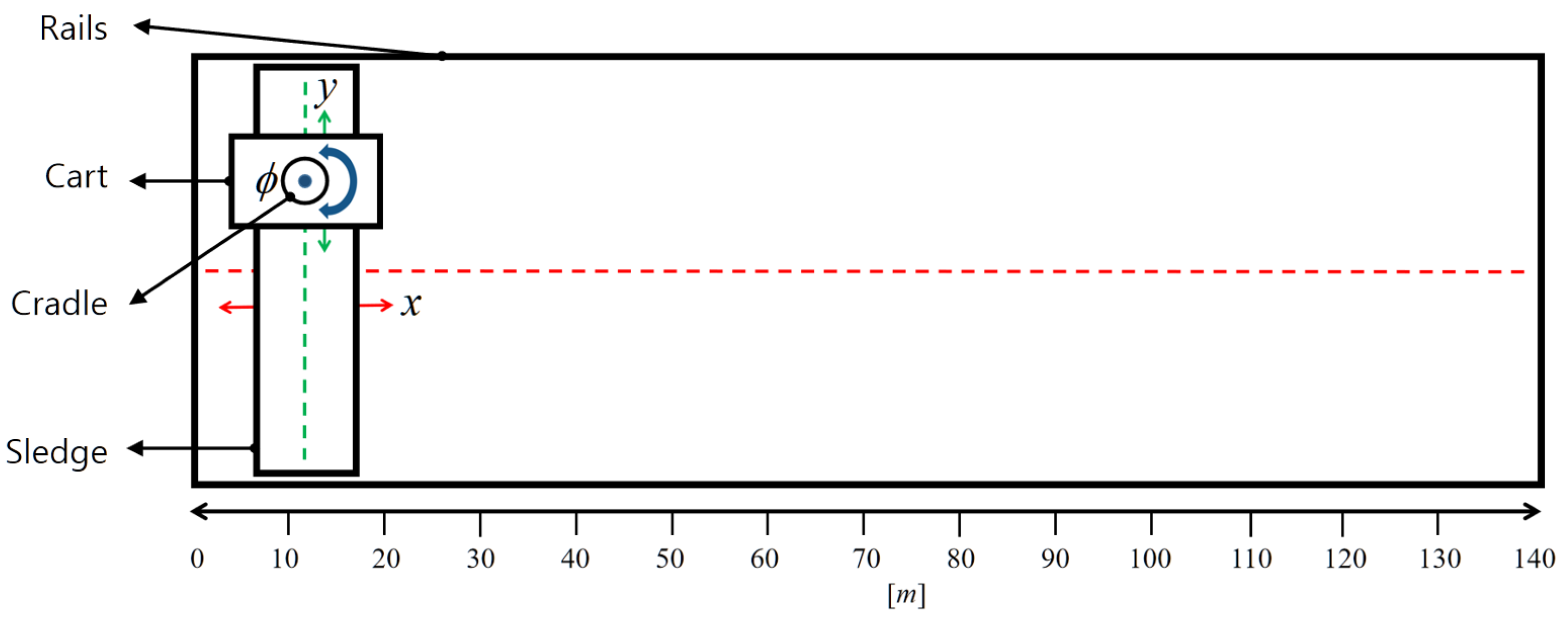
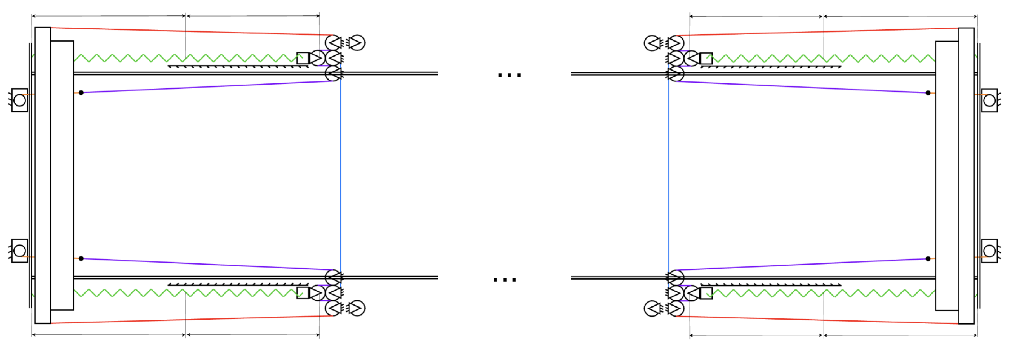
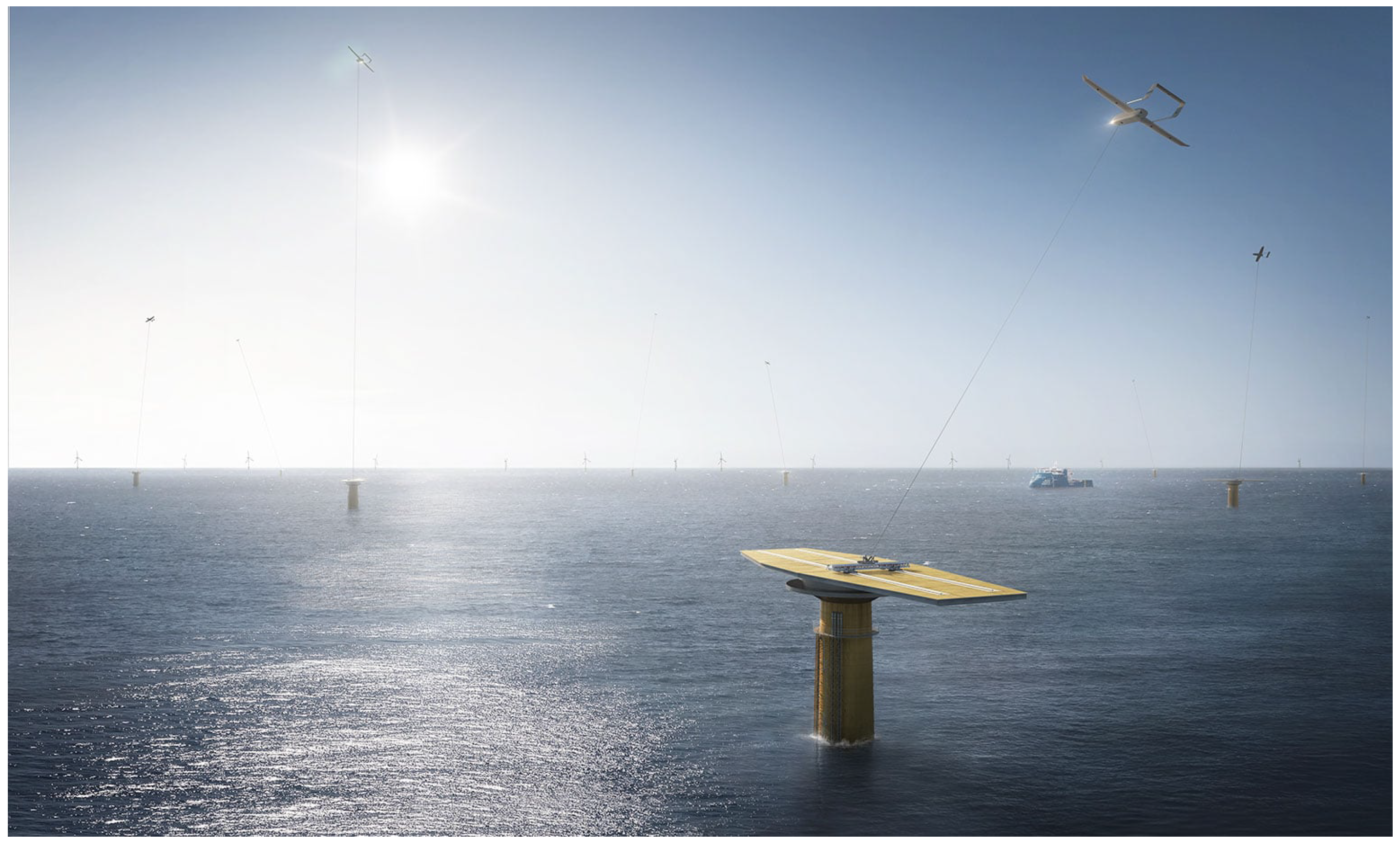
2.1. System Description

As illustrated in Figure 4, the carriage (2) acts as a ground system–aircraft interface and captures/releases the aircraft during take-off and landing. The carriage is also the suitable interface to lead the tether to a fixed ground generator. The carriage drives along the rails (3) (from left to right in Figure 5) and transmits acceleration or deceleration forces between the aircraft and the ground. For this purpose, the carriage incorporates electric motors and friction disc brakes in addition to the synchronisation actuators and sensors that are required for landing synchronisation. The enhanced BLLS design consists of a bungee trolley (1) that slides along the rails (3), which additionally transmits the force of the elastic cords (7) to the carriage (2) and vice versa (Figure 4). Two non-elastic ropes (4L and 4R) are attached to the left- and right-hand sides of the bungee trolley. A stationary pulley mechanism guides the ropes to the inner section of the rails, where they are eventually joined together (4) with the non-elastic rope of the winch (5) at the rope adapter (A). The winch (6) is fixed to the end piece of the rails at position x s , b l . The pulley mechanism connects the force of the elastic cords (7) to the non-elastic ropes via a sliding pulley (8), which is guided on a linear rail guide. The other end of the elastic cords is also fixed to the end piece of the rails at x s , b l , adjacent to the winch.
Prior to launch, the bungee trolley is positioned at x s , b l without any cord tension, where it is temporarily fixed to the end piece of the rails using permanent electromagnets (9). The carriage is slid back until it comes into contact with the bungee trolley. Then, the winch reels in its rope, which stretches the elastic cords along x e and builds up the potential energy of the system. At launch, the bungee trolley is released from the electromagnetic arresting mechanism, assisting the motors in pushing the carriage forwards along the first section of the rails until x f , b l (Figure 4). Thereafter, the carriage continues without the trolley, driven by its momentum and continuous motor force to launch or land the AWES UAV.
The landing, or deceleration process during landing, comprises the opposite behaviour. Prior to landing, the bungee trolley is positioned at the waiting position x f , b l and remains in a stationary state, as shown on the right-hand side (landing). The winch reels in the rope so that the elastic cords are straightened but not stretched. The carriage is positioned at the end of the ElektRail system, opposing the trolley position, and synchronises with the approaching aircraft before reaching an initial velocity (in the figure, from below) and colliding with the bungee trolley. To handle the impact of the collision, the bungee trolley is equipped with a shock absorption system. The carriage pushes the bungee trolley towards x s , b l , elongating the elastic cords until both the carriage and bungee trolley come to a stop.
The ElektRail architecture allows for the integration of a second parallel bungee cord system on the other rail (left-hand side in Figure 4) in order to increase force and acceleration. This arrangement is referred to as a double BLLS. For the ElektRail to function with the assistance of the BLLS during acceleration and deceleration, a double BLLS is mounted at each end of the ElektRail system (Figure 6), one to support acceleration and the other to support deceleration. In an attempt to optimise the overall length of the ElektRail, one end of the BLLS was designed with respect to the dynamics of the launch acceleration and the other was designed to handle the landing deceleration dynamics, which are the phases that require the maximum energy during the acceleration and deceleration processes. The space in between the two parallel rails is left unoccupied for the potential integration of a fixed ground generator AWE system.

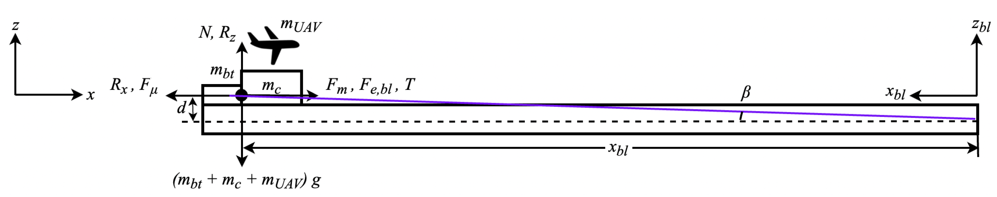
2.2. Mathematical Model

The system dynamics model of an ElektRail describes the motion of the carriage and takes into account other components that may be coupled with it. It depends on which phase of operation the system is in. The operations are broken down into landing and launch. During each operation cycle, there is an acceleration phase and a deceleration phase. In the acceleration phase, the carriage (with the UAV mounted on top) is propelled by both the elastic cords and the electric motors in parallel, as well as the UAV thrust if applicable. In the deceleration phase, the elastic cords and the electric motors act as brakes to bring the carriage to a halt. Additionally, a synchronisation phase is required during landing. During the synchronisation phase, the velocities and positions of the carriage and UAV are synchronised to allow for a smooth touchdown. At take-off, the synchronisation phase is not required. However, as the system length was designed according to the landing operation, there is still spare rail length available until deceleration begins. The coupling conditions for each operation phase are illustrated in Figure 7 and Table 1.
Following parameters and assumptions were considered in the system dynamics model:
  • The motor force F m is constant;
  • The UAV thrust force T is constant during take-off and any thrust variations caused by increased ground- or airspeed during take-off are neglected;
  • The impact of the UAV lift force R z on the normal force of the carriage N and thus, the respective friction force F μ during take-off are considered;
  • The aerodynamic drag force of the UAV R x is taken into account in additional to the drag force of the carriage F d r a g , c when applicable. The airspeed v a e r o is assumed for windless conditions and is equal to the velocity of the respective body relative to the stationary rail system;
  • The UAV acceleration/deceleration is limited to 5 g to preserve structural integrity;
  • Maximum carriage acceleration/deceleration (without the UAV connected to it) is limited to 10 g to preserve structural integrity;
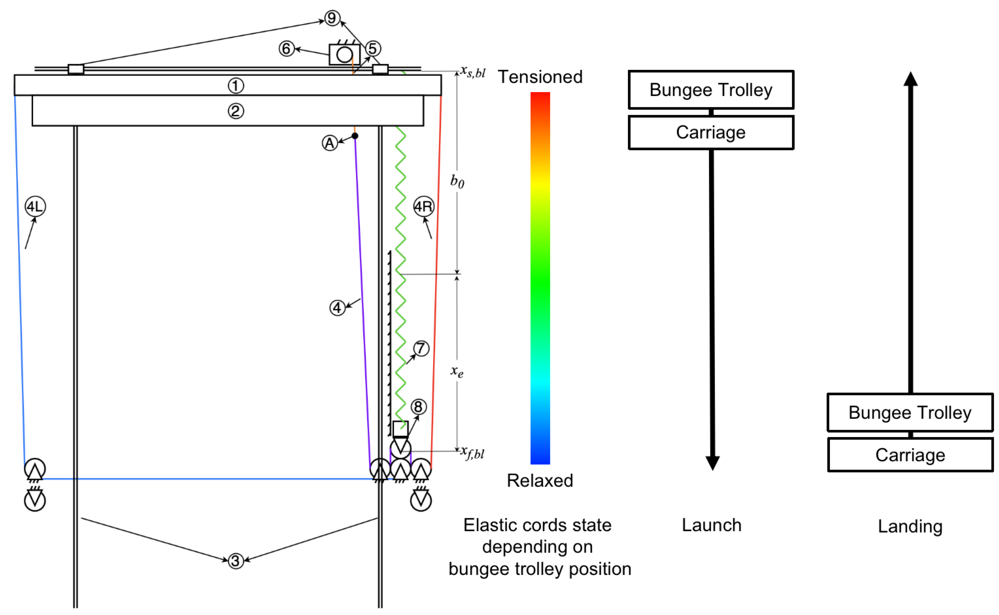
  • The inclination angle β of the non-elastic ropes is positioned relative to the horizontal system (Figure 8);
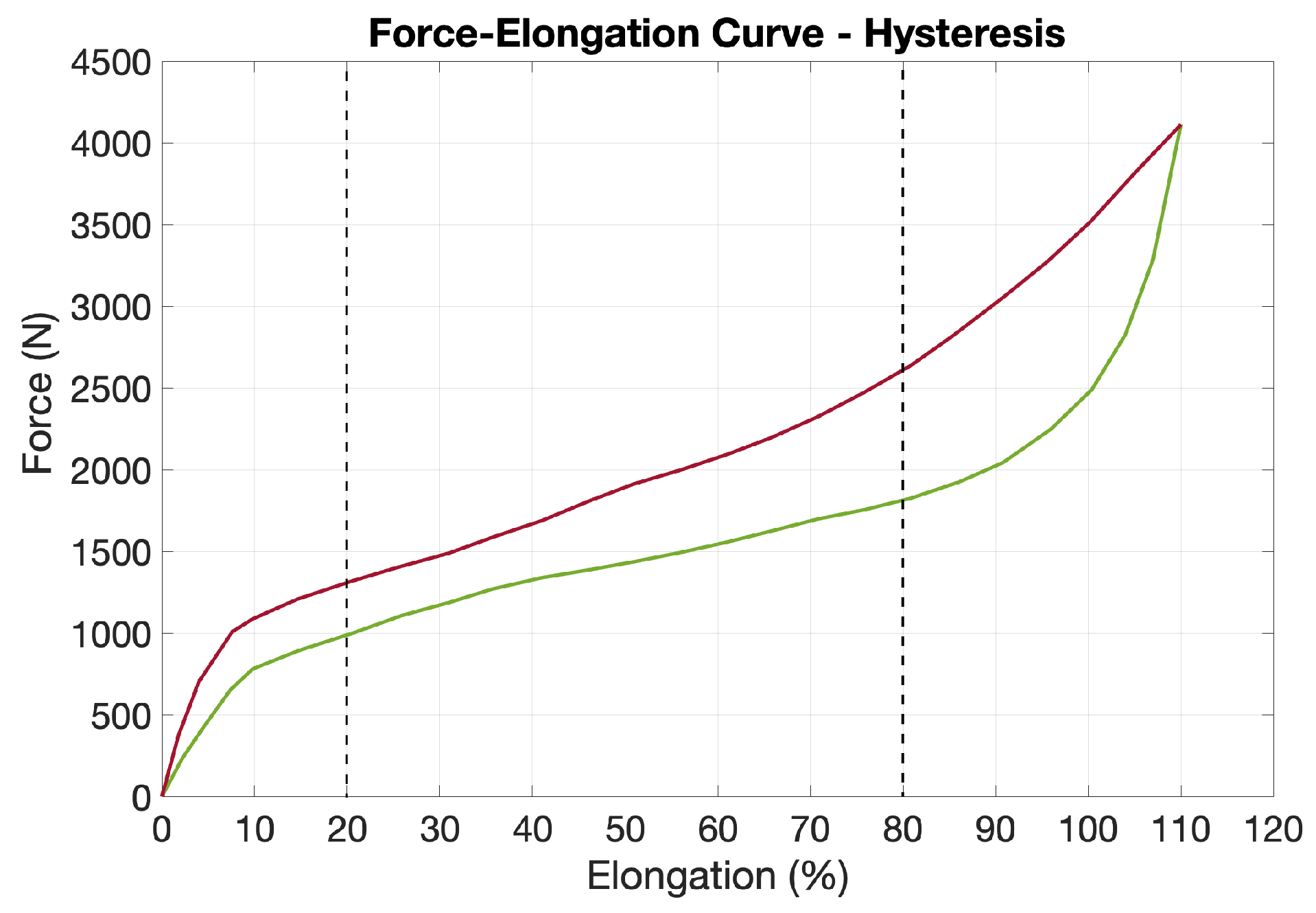
  • The hysteresis of the elastic ropes results in a rebounding force F e r is different from a stretching force F e s ;
  • The braking force F b r is constant;
  • The mass of the carriage m c , UAV m u a v and bungee trolley m b t are taken into account when applicable;
  • The rope winding over the pulleys, as well as electric friction disk motors, is assumed to be without slipping;
  • Coupled bodies are treated as one body;
  • The motors can operate at full power in the reverse direction and hence, F b r , m a x = F m , m a x ;
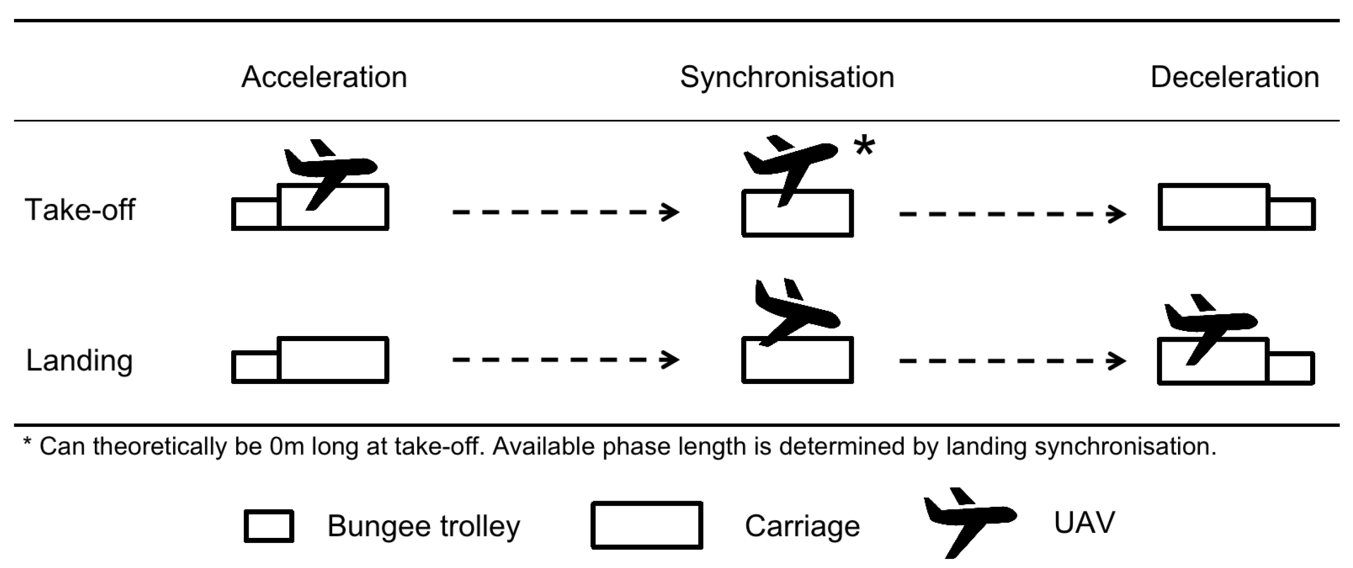
  • The landing operation must incorporate a minimum synchronisation window of t s y n c = 0.2 s as tolerance for the touchdown on the carriage;
  • The take-off and landing velocities of the UAV are assumed to be 25 m/s.
The following parameters were neglected in the modelling process:
  • The mass of the elastic cords;
  • The mass of the non-elastic ropes, pulleys and slider;
  • Any friction forces in the bearings;
  • The work of the friction force when the UAV slips off the carriage.
The model was built as follows:
The elongation of the elastic cords x e could be expressed in terms of the bungee trolley position on the rails with respect to the BLLS coordinate system x b l [16] as:
x e = 1 2 x b l .
The rebounding and stretching forces F e , 1 of an elastic cord were expressed in terms of x e as:
F e , 1 = F e r , 1 = i = 0 8 p i x e i , if   x b l > 0 , F e s , 1 = i = 0 8 p i i x e i , if   x b l < 0 .
As shown in Figure 9, the approximated function represented the force–elongation curve of a single elastic cord that was derived from a dataset provided by the manufacturer in [16]. The values of the coefficients were derived for single elastic cords of lengths b 0 = 5 m and b 0 = 5.5 m, as were used in the acceleration and deceleration BLLSs, respectively (Table 2 and Table 3).
Hence, the total force of the elastic cords, consisting of n e parallel elastic cords in each BLLS and n b l BLLSs used in parallel, was:
F e = n b l n e F e , 1 = F e r = n b l n e F e r , 1 , if   x b l > 0 , F e s = n b l n e F e s , 1 , if   x b l < 0 .
When the pulley mechanism and the inclination angle β , as illustrated in Figure 8, were taken into account, the effective force of the elastic cords on the bungee trolley F e , b l could be expressed as:
F e , b l = F e 2 cos β = F e r , b l = F e r 2 cos β , if   x b l > 0 , F e s , b l = F e s 2 cos β , if   x b l < 0 .
The force F e , b l was transmitted to the bungee trolley via the non-elastic ropes. As the trolley was not always coupled to the carriage, the effective elastic force on the carriage was:
F e , c = F e r , c = F e r 2 cos β , if   x b l > 0 , 0 , if   x b l < 0 , F e s , c = F e s 2 cos β , if   x b l > 0 , 0 , if   x b l < 0 .
The aerodynamic drag forces of the carriage and UAV were expressed as in Equations (6) and (7), respectively:
F d r a g , c = C d , c ρ a i r A c v a e r o 2 2
R x = C d , u a v ρ a i r A u a v v a e r o 2 2
The resultant normal force varied with respect to the coupled bodies of the bungee trolley (BT), carriage (C) and UAV and equalled:
N = m b t + m c + m u a v g + F e 2 sin β R z sign x ˙ b l , for   BT ,   C   and   UAV , m b t + m c g + F e 2 sin β sign x ˙ b l , for   BT   and   C , m c + m u a v g R z sign x ˙ b l , for   C   and   UAV , m c g sign x ˙ b l , for   C , m b t g + F e 2 sin β sign x ˙ b l , for   BT .
where the lift force of the UAV is expressed as:
R z = C l , u a v ρ a i r A u a v v a e r o 2 2 .
Hence, the friction force was:
F μ = μ N .
sin β and cos β were derived from the geometry illustrated in Figure 8:
sin β = d x b l 2 + d 2
cos β = x b l x b l 2 + d 2
The numerical values for the force of the electric motors F m , the thrust force of the UAV T and the braking force resulting from the operation of the motors in the reverse direction F b r are shown in Table 4 [14].
The equation of motion that described the carriage during the acceleration phase was:
F i n + F d r a g + F μ F t = 0 .
where F i n is the total inertial force, F d r a g is the total aerodynamic force, F μ is the applicable friction force and F t is the effective propelling force of the carriage. During the deceleration phase, the motion of the carriage was described by:
F i n + F μ + F d r a g + F b r + F e s , b l = 0 .
For a take-off operation, the carriage motion was described by the following:
Take-off acceleration:
x ¨ b l = C d , c A c + C d , u a v + μ C l , u a v sign x ˙ b l A u a v ρ a i r 2 m b t + m c + m u a v x ˙ b l 2 μ g sign x ˙ b l | x b l | + μ d 2 m b t + m c + m u a v x b l 2 + d 2 F e r F m + T m b t + m c + m u a v
Take-off deceleration:
x ¨ b l = C d , c ρ a i r A c 2 m b t + m c x ˙ b l 2 μ g sign x ˙ b l | x b l | + μ d 2 m b t + m c x b l 2 + d 2 F e s F b r m b t + m c
The landing operation was expressed as:
Landing acceleration:
x ¨ b l = C d , c ρ a i r A c 2 m b t + m c x ˙ b l 2 μ g sign x ˙ b l | x b l | + μ d 2 m b t + m c x b l 2 + d 2 F e r F m m b t + m c
Landing deceleration:
x ¨ b l = C d , c A c + C d , u a v + μ C l , u a v sign x ˙ b l A u a v ρ a i r 2 m b t + m c + m u a v x ˙ b l 2 μ g sign x ˙ b l | x b l | + μ d 2 m b t + m c + m u a v x b l 2 + d 2 F e s F b r m b t + m c + m u a v
The equation of motion describing the decoupled bungee trolley after the acceleration phase of either the landing or take-off operation was:
x ¨ b l = μ g sign x ˙ b l | x b l | + μ d 2 m b t x b l 2 + d 2 F e .
So far, the dynamics were expressed in terms of the BLLS coordinate system x b l , y b l , z b l . The dynamics of the carriage could be further expressed in terms of the ElektRail coordinate system x , y , z . For acceleration, the transformation equations were:
x = l B L L S x b l ,
x ˙ = x ˙ b l ,
x ¨ = x ¨ b l .
where l B L L S is the length of a BLLS, defined by:
l B L L S = x f , b l = b 0 + x e = b 0 + e b 0 .
where e is the percentage of the elongation of the elastic cords. The transformation for deceleration was:
x = x b r , i + x b l ,
x ˙ = x ˙ b l ,
x ¨ = x ¨ b l .
where x b r , i is the position of the carriage on the ElektRail prior to entering the deceleration phase. x b r , i is assumed to be zero for simplicity.

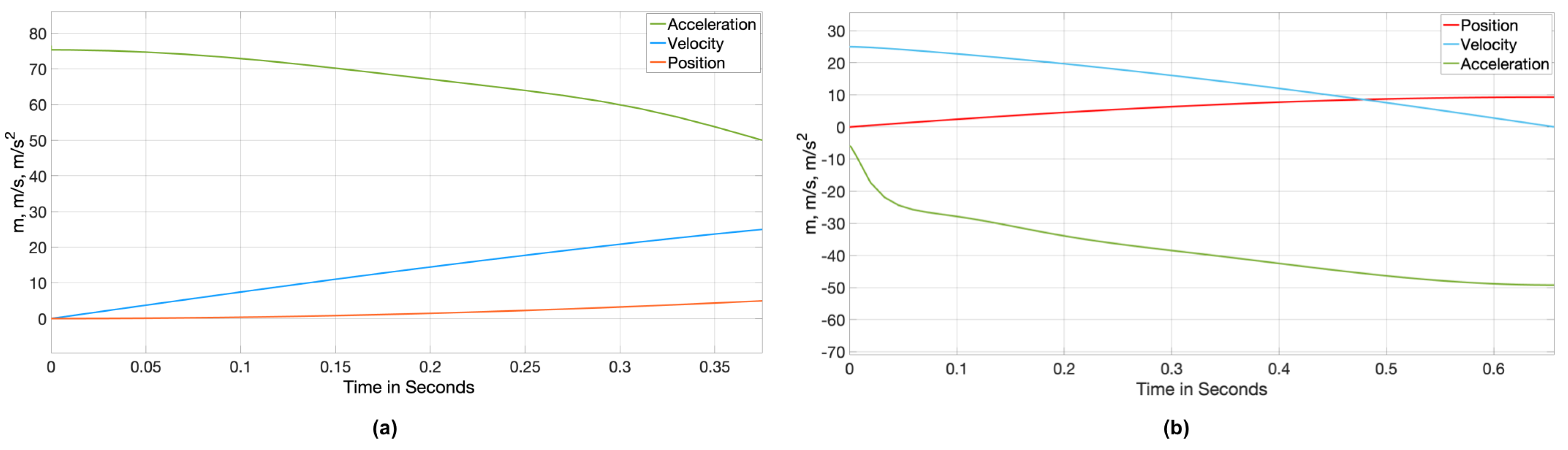
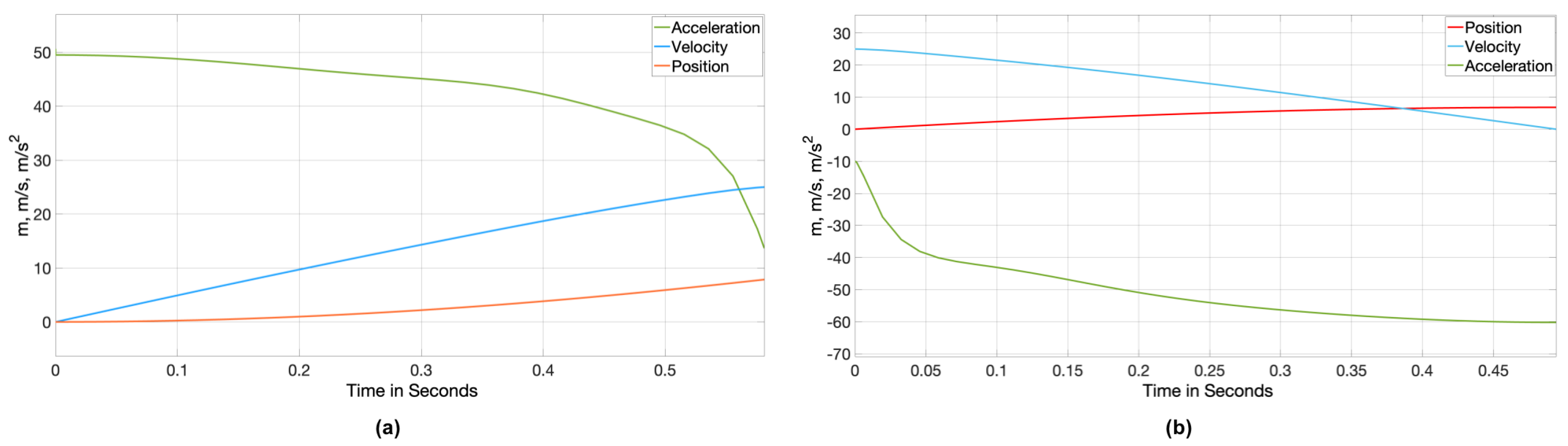
3. Results and Discussion

3.1. Results

In the following section, we analysed the carriage dynamics during landing and take-off. The findings were further used to anticipate the overall ElektRail length. The equations of motion were solved with regard to the system parameters in Table 5, which represent plausible values that were close to the Ampyx Power AP3 demonstrator.
In an attempt to minimise the ElektRail length, the acceleration and deceleration BLLSs were designed to operate in a more linear behaviour. Furthermore, both BLLSs utilised a different number n e and length b 0 of elastic cords in the process (Table 6 and Table 7).
The carriage dynamics during landing are illustrated in Figure 10 and Table 8 and Table 9. During the landing acceleration phase of the carriage without the aircraft (a), the maximum acceleration value occurred as the cords were at maximum tension before diminishing slightly. In reverse, the deceleration built up in (b) as the carriage with the captured aircraft increased tension in the cords. Both curves were complemented by the electric motors.
The carriage dynamics during take-off are demonstrated in Figure 11 and Table 10 and Table 11. During take-off acceleration (a), the overall acceleration was lower compared to the landing acceleration as the same force had to move a significantly higher mass. Stopping the carriage without the aircraft, however, led to the somewhat higher deceleration in (b) compared to the landing phase in Figure 10.
As shown earlier in Figure 9, the most linear behaviour of the elastic cords was demonstrated in the range of 20 % e 80 % . The initial elongation of the elastic cords prior to acceleration was thus limited to e i = 80 % , as seen in Table 8 and Table 10. Moreover, the BLLS design parameters were selected so that the final elongation reached at deceleration e f was kept within the most linear region (Table 9 and Table 11).
The acceleration and deceleration BLLSs required a minimum length on the ElektRail (Figure 12) for each launch and landing. These lengths could be calculated using Equation (23) with respect to the elastic cords of length b 0 = 5.5 and the maximum elongations of e i = 80 % and e f = 69.3% for acceleration and deceleration, resulting in l B L L S , a c c = 9 m and l B L L S , d e c = 9.3 m. Assuming that Δ x l a l B L L S Δ x t d , the required ElektRail lengths for take-off L t and landing L l could be expressed as:
L l = max ( Δ x l a + x s y n c , l B L L S , a c c ) + max ( Δ x l d , l B L L S , d e c ) = 19.3   m ,
L t = max ( Δ x t a , l B L L S , a c c ) + max ( Δ x t d , l B L L S , d e c ) = 18.3   m .
where x s y n c is the distance travelled by the carriage at a constant velocity of v s y n c = 25 m/s during a t s y n c = 0.2 s synchronisation window, which equated to:
x s y n c = v s y n c t s y n c = 5   m .
As can be observed from Equations (27) and (28), the length required for landing was more than the length required for launch. Hence, the required ElektRail length was:
L = max ( L l , L t ) = 19.3m .
Table 12 shows a sensitivity analysis regarding the theoretically longer synchronisation times.

3.2. Discussion

A fixed-wing AWES launched and recovered by an ElektRail ground system could unlock design improvements for airborne configurations.
The ElektRail system length could already be limited to 19.3 m as a concept. This is below the desired maximum 30 m requirement for a compact offshore platform, assuming a landing synchronisation phase of 0.2 s. Despite this short synchronisation time, a robust control scheme seems achievable as synchronisation control already begins during the approach and acceleration of the carriage before the UAV is due to touch down. A sensitivity analysis regarding longer synchronisation times was performed in Table 12. However, it is likely that the achieved system length could be incrementally shortened even further through the optimisation of the elastic cord choice (especially in force–elongation behaviour), the number of parallel cords and BLLS length. Furthermore, an interactive electric motor controller regime could allow for a stronger BLLS peak force without exceeding the acceleration limits imposed by the UAV (5 g) or the carriage (10 g). During the peak force of the cords at maximum elongation, the motor force could be reduced or even reversed so as not to exceed the limit despite the use of stronger or a higher number of cords.
As the cord peak force increases, the ElektRail rail structure in the BLLS area needs to be reinforced to compensate for the high tension forces. However, this would not have an impact on the system dynamics as it only concerns static mass and therefore, is only considered as a detailed implementation design.
Limitations for this approach could arise regarding the further scaling of the AWE vehicle size and mass as this requires a proportional increase in the acceleration and deceleration forces. However, this becomes increasingly difficult as the individual cords are only commercially available up to a certain strength and the use of cords in parallel results in complexity and integration space issues. Furthermore, there is an open question as to how durable elastic cords would be in a challenging maritime environment, with salt water spray combined with long durations of sun exposure and, in some locations, potentially ice.
As shown in the theoretical system dynamics calculation in Equation (31), the theoretical minimum ElektRail system length with a non-power limited actuator, whilst preserving UAV and carriage g-limits, is 14.6 m.
The acceleration rate a is linked to the displacement s (determining the required length of the acceleration section) via the following relationship, while v f is the terminal velocity and v i is the initial velocity. Thus, a equates to
a = v f 2 v i 2 2 s
and results in system length requirements of Table 13.
As an alternative to a BLLS approach, future work may want to explore different actuator concepts, such as long stator linear synchronous motor LMDs, which have been proven in roller coaster actuation systems, for example, and are capable of at least 10 g acceleration, more than 200 kN of force and high dynamic actuation precision. Furthermore, this kind of linear motor allows the energy supply, such as batteries, controllers and most of the motor mass itself to be integrated into the static subsystem, thereby saving mass on the moving carriage and increasing dynamic performance further or alternatively reducing power requirements. A significant consideration of this approach, however, would be system costs and how much these could be reduced by shortening the system length in a mass production scenario. Hence, the authors strongly encourage further investigation in this direction to push the boundaries of system compactness [17,18].
As proposed by Fagiano et al. [5], winch-pulled longitudinal carriage actuation via a belt or rope could also be a viable and low-cost design. However, the dynamic elongation effects of the belt or rope could significantly impact the actuation control precision. Having onboard electric motors for the carriage would compensate for the potential control challenges that could be induced by the dynamic elongation effects.
Regarding robustness against failures and repeatability, the long stator linear synchronous motor actuation would most likely be superior to both bungee cord-enforced electric motor actuation and winch-pulled carriage actuation as it would involve an electromagnetic system with a minimal number of moving parts.
The architecture of the ElektRail qualifies it to serve both a fixed ground generator AWES and an open loop rail moving ground generator AWES. Further investigation is required to determine the optimal way in which the UAV tether can safely interact with the system during touchdown, despite the presence of an ElektRail interface. In principle, the tether integration could work in a similar manner to [5], where there is also a landing carriage that carries the tether. In order to provide the required tether slag or tension, the ground generator/motor needs to compensate for the actuated movement of the carriage and additionally, reel the required tether length in or out in addition to monitoring the aircraft’s flight position. Despite these general considerations, UAV–tether interface designs have not yet been the subject of investigation and are closely related to overall UAV designs, as well as carriage interface designs.
The increased airborne wind energy power output needs to be quantified in future studies. Mass savings from just the elimination of heavy landing gear while only keeping the structural hard points are deemed to be very likely. Furthermore, a significant redesign of the UAV configuration itself from a dual fuselage to a single fuselage, while eliminating significant airborne mass as well as aerodynamic drag, appears desirable. The optimisation of both the landing gear and the fuselage would allow for more of the wing-generated lift to be used as productive work transferred to the generator via the tether as opposed to being dissipated in flight physics losses. The extent to which this would translate into the increased power output of an optimised airborne wind energy system remains to be modelled in future studies.

4. Conclusions

This paper showed that the ElektRail UAV launch and landing concept can be enhanced with bungee cord support acceleration devices at each end of the launch and landing rails. The system length can be reduced to 19.3 m and thus, is of a magnitude that is suitable for the intended use in airborne wind energy systems on offshore platforms. Furthermore, by switching to the entirely different actuator concept of long stator linear motors, the system dynamics could potentially be further improved to a system length of just 14.6 m without exceeding the maximum acceleration forces for the flying system component of the AWE system. While working prototypes of ElektRail for fixed-wing UAVs exist, an AWES-adapted prototype is yet to be built.
Hence, it can be concluded that an ElektRail launch and landing concept could be a worthwhile consideration in order to reduce the mass of the flying system component and thus, increase the net power yield of the overall system. Significant mass savings can already be achieved by simply transferring large parts of the landing gear function to ground-based equipment. As discussed above, considerably larger mass savings can be expected in the overall redesign of the flying system component into a lighter and more aerodynamic single fuselage configuration. This could be enabled by higher propeller ground clearance, as well as improved mechanical stability from an ElektRail interface with the flying component.
All in all, an ElektRail launch and landing concept that is adapted for offshore airborne wind energy systems, as depicted in Figure 13, seems worthwhile to explore further.

Author Contributions

Conceptualisation, J.A.M. and M.Y.M.K.E.; methodology, J.A.M. and M.Y.M.K.E.; software, M.Y.M.K.E.; validation, J.A.M. and M.Y.M.K.E.; formal analysis, J.A.M. and V.G.; investigation, J.A.M. and M.Y.M.K.E.; resources, M.Y.M.K.E.; data curation, M.Y.M.K.E.; writing—original draft preparation, J.A.M. and M.Y.M.K.E.; writing—review and editing, J.A.M. and V.G.; visualisation, M.Y.M.K.E.; supervision, V.G.; project administration, J.A.M.; funding acquisition, J.A.M. All authors have read and agreed to the published version of the manuscript.

Funding

This research was funded by Bundesministerium für Wirtschaft und Energie, grant number 20Q1958D.

Institutional Review Board Statement

Not applicable.

Informed Consent Statement

Not applicable.

Data Availability Statement

Not applicable.

Acknowledgments

The authors would like to give special thanks to Jan Binnebesel of MB and Partners who contributed with valuable advice regarding the ElektRail launch and landing system.

Conflicts of Interest

The authors declare no conflict of interest.

Nomenclature

The following nomenclature are used in this manuscript:
m u a v UAV mass
m c Carriage mass
m b t Bungee trolley mass
A c Cross-sectional area of the carriage
A u a v Aerodynamic surface of the wing
C d , u a v Drag force coefficient of the UAV
C d , c Drag force coefficient of the carriage
C l , u a v Lift force coefficient of the UAV
dVertical offset between the bungee trolley and pulleys
μ Rolling friction coefficient
ρ Air density
b 0 Length of the elastic cords
n b l Number of BLLSs in parallel
n e Number of elastic cords in parallel in a BLLS
e i Percentage of initial elongation of the elastic cords
e f Percentage of final elongation of the elastic cords
ePercentage of elongation of the elastic cords
Δ x t a Total distance travelled by the carriage during the launch acceleration phase
Δ x t d Total distance travelled by the carriage during the launch deceleration phase
Δ x l a Total distance travelled by the carriage during the landing acceleration phase
Δ x l d Total distance travelled by the carriage during the landing deceleration phase
Δ v t a Velocity change of the carriage during the launch acceleration phase
Δ v t d Velocity change of the carriage during the launch deceleration phase
Δ v l a Velocity change of the carriage during the landing acceleration phase
Δ v l d Velocity change of the carriage during the landing deceleration phase
Δ t t a Duration of the launch acceleration phase
Δ t t d Duration of the launch deceleration phase
Δ t l a Duration of the landing acceleration phases
Δ t l d Duration of the landing deceleration phase
a t a , m a x Maximum acceleration rate reached by the carriage during the launch
acceleration phase
a t d , m a x Maximum acceleration rate reached by the carriage during the launch
deceleration phase
a l a , m a x Maximum acceleration rate reached by the carriage during the landing
acceleration phase
a l d , m a x Maximum acceleration rate reached by the carriage during the landing
deceleration phase
l B L L S Length of a BLLS
l B L L S , a c c Length of the acceleration BLLS
l B L L S , d e c Length of the deceleration BLLS
L l Required ElektRail system length for landing
L t Required ElektRail system length for launch
LRequired ElektRail system length
x s y n c Distance travelled by the carriage during the synchronisation window
v s y n c Velocity of the carriage during the synchronisation window
t s y n c Duration of the synchronisation window
x f , b l End position of the BLLS on the ElektRail and bungee trolley position on the
ElektRail when the elastic cords are fully relaxed
x s , b l Start position of the BLLS on the ElektRail and bungee trolley position on the
ElektRail when the elastic cords are elongated with the maximum e of a
respective BLLS
x b r , i Carriage position on the ElektRail prior to deceleration
xPosition relative to the ElektRail coordinates
x ˙ Velocity relative to the ElektRail coordinates
x ¨ Acceleration relative to the ElektRail coordinates
x b l Position relative to the BLLS coordinates
x ˙ b l Velocity relative to the BLLS coordinates
x ¨ b l Acceleration relative to the BLLS coordinates
F m Forward force of the eight electric BLDC motors
F b r Braking force of the eight electric BLDC motors
gGravitational acceleration
β Inclination angle of the ropes due to the vertical offset d and horizontal offset
x b l between the bungee trolley and the pulleys
F i n Total inertial force
F d r a g Total aerodynamic drag force
F μ Total friction force
F t Total effective propelling force
F e r , b l Effective rebounding force of the elastic cords on the bungee trolley
F e s , b l Effective stretching force of the elastic cords on the bungee trolley
F e , b l Effective force of the elastic cords on the bungee trolley
F e r , c Effective rebounding force of the elastic cords on the carriage
F e s , c Effective stretching force of the elastic cords on the carriage
F e , c Effective force of the elastic cords on the carriage
R x Aerodynamic drag force of the UAV
R z Lift force of the UAV
F d r a g , c Aerodynamic drag force of the carriage
NTotal normal force
TThrust force of the UAV
F e r Rebounding force of the elastic cords
F e s Stretching force of the elastic cords
F e Force of the elastic cords
F e r , 1 Rebounding force of one elastic cord
F e s , 1 Stretching force of one elastic cord
F e , 1 Force of one elastic cord
x e Elongated length of the elastic cords
aAcceleration of an LMD
sDisplacement of an LMD
v f Final velocity of an LMD
v i Initial velocity of an LMD

Abbreviations

The following abbreviations are used in this manuscript:
AWEAirborne Wind Energy
AWESAirborne Wind Energy System
BLDCBrushless Direct Current Motor
BLLSBungee Launch and Landing System
BTBungee Trolley
CCarriage
GroLaSGround-based Landing Gear System
LMDLinear Motor Drive
uSTOLUltra-Short Take-off and Landing
xSTOLExtra-Short Take-off and Landing
UAVUnmanned Aerial Vehicle

References

  1. Diehl, M. Airborne Wind Energy: Basic Concepts and Physical Foundations. In Airborne Wind Energy. Green Energy and Technology; Ahrens, U., Diehl, M., Schmehl, R., Eds.; Springer: Heidelberg, Germany, 2 October 2013. [Google Scholar]
  2. Fagiano, L.; Schnez, S. On the take-off of airborne wind energy systems based on rigid wings. Renew. Energy 2017, 107, 473–488. [Google Scholar] [CrossRef]
  3. Fagiano, L.; Nguyen-Van, E.; Rager, F.; Schnez, S.; Ohler, C. A Small-Scale Prototype to Study the Takeoff of Tethered Rigid Aircrafts for Airborne Wind Energy. IEEE/ASME Trans. Mechatron. 2017, 22, 1869–1880. [Google Scholar] [CrossRef]
  4. Fagiano, L.; Nguyen-Van, E.; Schnez, S. Linear take-off and landing of a rigid aircraft for airborne wind energy extraction. In Airborne Wind Energy. Green Energy and Technology; Schmehl, R., Ed.; Springer: Singapore, 2018; pp. 491–514. [Google Scholar]
  5. Fagiano, L.; Nguyen-Van, E.; Rager, F.; Schnez, S.; Ohler, C. Autonomous Takeoff and Flight of a Tethered Aircraft for Airborne Wind Energy. IEEE Trans. Control Syst. Technol. 2017, 26, 151–166. [Google Scholar] [CrossRef]
  6. Cherubini, A.; Papini, A.; Vertechy, R.; Fontana, M. Airborne Wind Energy Systems: A review of technologies. Renew. Sustain. Energy Rev. 2015, 51, 1461–1476. [Google Scholar] [CrossRef]
  7. Kruijff, M.; Ruiterkamp, R. A Roadmap Towards Airborne Wind Energy in the Utility Sector. In Airborne Wind Energy. Green Energy and Technology; Schmehl, R., Ed.; Springer: Singapore, 1 April 2018; pp. 643–662. [Google Scholar]
  8. Williams, P.; Paz, M.; Kruijff, M.; Steenhuizen, D. Autonomous Takeoff and Landing of Rigid Wing Airborne Wind Energy Systems. In Proceedings of the Airborne Wind Energy Conference 2019, Glasgow, UK, 15–16 October 2019; Available online: http://resolver.tudelft.nl/uuid:07846942-7d5a-4c57-9fc6-01c639b95d41 (accessed on 1 February 2022). [CrossRef]
  9. Drenth, S. Wave Limitations for Floating AWES: A Method for Determining Effects of Wave Induced Motions on Horizontally Landing Airborne Wind Energy Systems on Floating Foundations. 2017. Available online: http://resolver.tudelft.nl/uuid:6e3d5671-9e0a-42ff-8d53-2a4923731632 (accessed on 1 February 2022).
  10. Vimalakanthan, K.; Caboni, M.; Schepers, J.G.; Pechenik, E.; Williams, P. Aerodynamic analysis of Ampyx’s airborne wind energy system. J. Phys. Conf. Ser. 2018, 1037, 062008. [Google Scholar] [CrossRef]
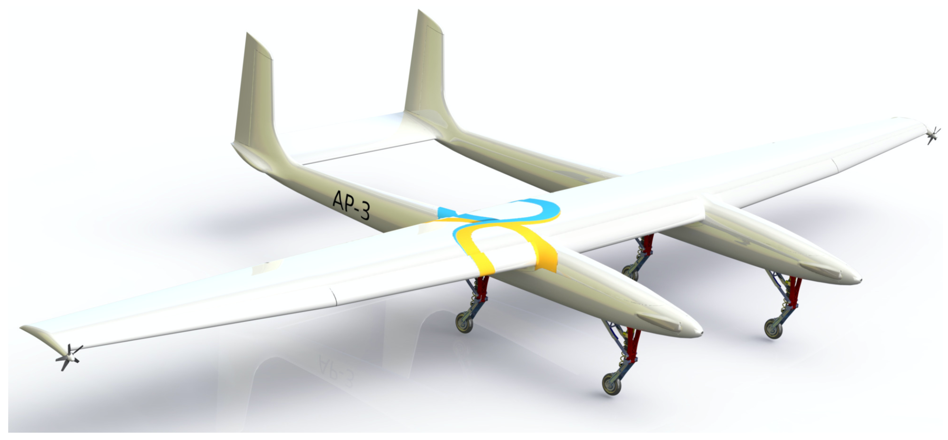
  11. Kruijff, M.; Ruiterkamp, R. AP-3, a Safety and Autonomy Demonstrator for Utility-Scale Airborne Wind Energy. In Proceedings of the Airborne Wind Energy Conference 2017, Freiburg im Breisgau, Germany, 5–6 October 2017; Available online: http://resolver.tudelft.nl/uuid:53286eb3-3e58-4f33-accf-c80c4876a60a (accessed on 1 February 2022).
  12. Brodrick, T.; Tabor, S.; Rebbeck, H. Effect of Mass on Airborne Wind Energy Performance. In Proceedings of the Airborne Wind Energy Conference 2019, Glasgow, UK, 15–16 October 2019; Available online: http://resolver.tudelft.nl/uuid:c390a5bc-4e7b-4f1d-861a-ed15fd407ae6 (accessed on 1 February 2022).
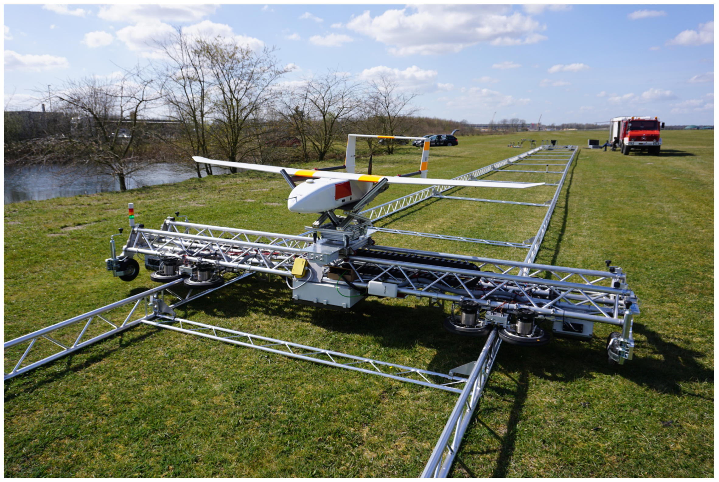
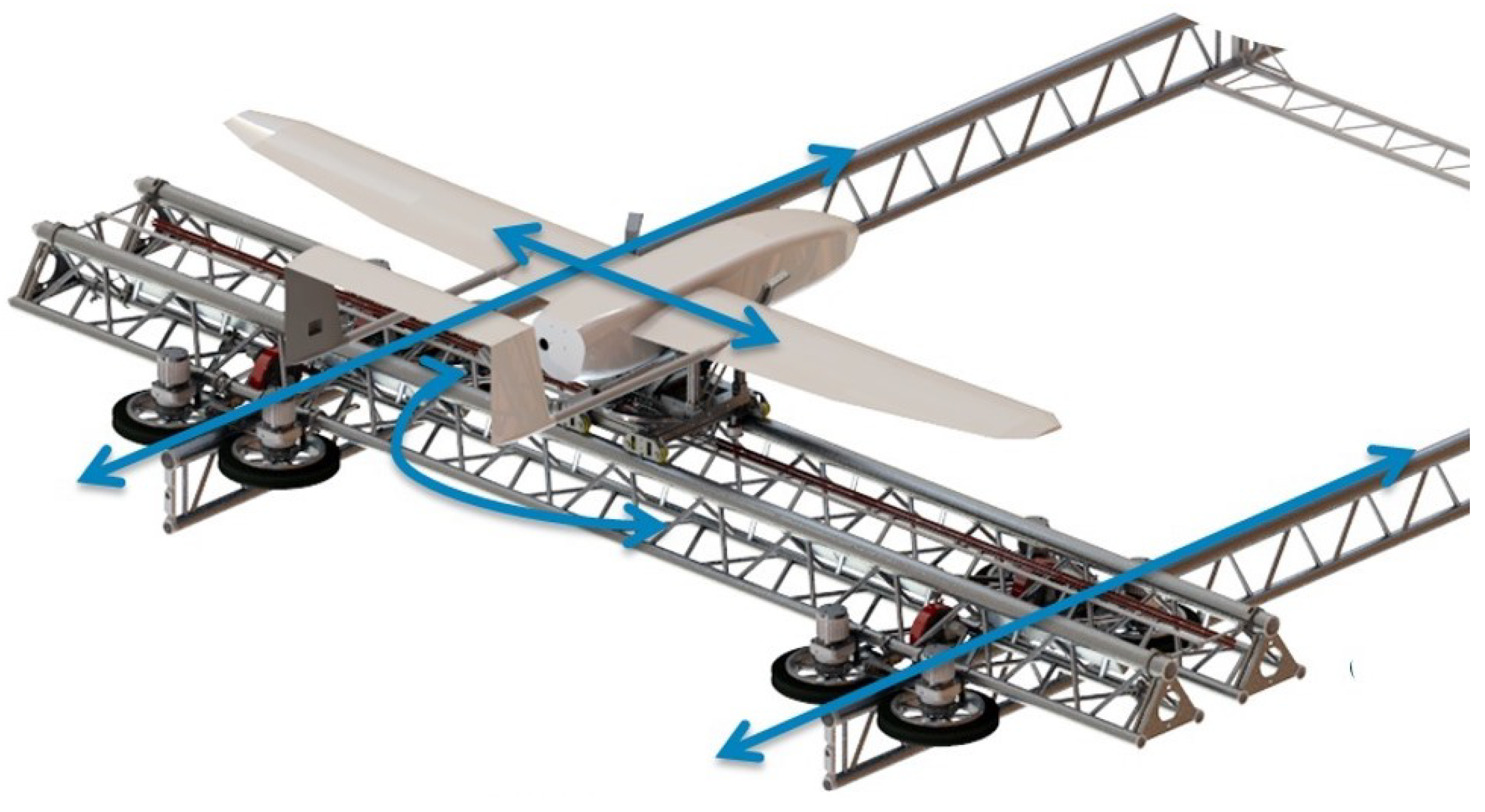
  13. ElektRail. Available online: https://www.elektrail.com (accessed on 2 November 2021).
  14. Elhashash, M. System Design for Shortened ElektRail UAV Launch and Landing System for Airborne Wind Energy Generation from Offshore Platforms. Master’s Thesis, Deutsches Zentrum für Luft und Raumfahrt e.V. (DLR), Institute für Lufttransportsysteme (ILT), Technische Universität Hamburg (TUHH), Hamburg, Germany, 2021. [Google Scholar]
  15. Elhashash, M. Development and Implementation of Four Functionality Modes for a Track-Based Launch and Landing System. Project Thesis, Deutsches Zentrum für Luft und Raumfahrt e.V. (DLR), Institute für Lufttransportsysteme (ILT), Technische Universität Hamburg (TUHH), Hamburg, Germany, 2020. [Google Scholar]
  16. Novakovic, Z.; Medar, N.; Mitrovic, L. Increasing Launch Capability of a UAV Bungee Catapult. Sci. Tech. Rev. 2014, 64, 17–26. [Google Scholar]
  17. INTRASYS. Available online: https://intrasys-gmbh.com/lineare-antriebstechnik/das-slim-antriebssystem/ (accessed on 26 October 2021).
  18. AEROTECH. Available online: https://www.aerotech.com/wp-content/uploads/2020/12/linear-motors-application-en.pdf (accessed on 26 October 2021).
Figure 1. The Ampyx Power AP3 featuring a quadruple landing gear [11].
Energies 15 02502 g001
Figure 2. An ElektRail prototype.
Energies 15 02502 g002
Figure 3. An ElektRail CAD model.
Energies 15 02502 g003
Figure 4. The top view of one end of the ElektRail with a BLLS (components described in the text).
Energies 15 02502 g004
Figure 5. A schematic diagram of the ElektRail system.
Energies 15 02502 g005
Figure 6. The architecture of an ElektRail equipped with double BLLS acceleration/deceleration sections on the left- and right-hand sides of the figure. (A part of the rail length in between is not shown).
Energies 15 02502 g006
Figure 7. The coupled bodies for each operational phase.
Energies 15 02502 g007
Figure 8. A free-body diagram of the BLLS-enhanced ElektRail.
Energies 15 02502 g008
Figure 9. The force–elongation curve and hysteresis of the assumed elastic cord. F e r , 1 and F e s , 1 are indicated in green and red, respectively.
Energies 15 02502 g009
Figure 10. The carriage dynamics due to the landing acceleration phase (a) and the landing deceleration phase (b).
Energies 15 02502 g010
Figure 11. The carriage dynamics at take-off during the acceleration phase (a) and deceleration phase (b).
Energies 15 02502 g011
Figure 12. An explanatory schematic of the required length of the ElektRail.
Energies 15 02502 g012
Figure 13. A rendering of an offshore wind farm for future AWES with ElektRail launch and landing systems.
Energies 15 02502 g013
Table 1. The associated force and mass parameters for each phase of operation.
Take-OffLanding
Acceleration F e r , F m , T, F μ , R x , R z F e r , F m , F μ
m b t , m c , m u a v m b t , m c
Synchronisation F m , F μ F m , F μ
m c , m u a v m c
Deceleration F e s , F b r , F μ F e s , F b r , F μ , R x , R z
m c , m b t m b t , m c , m u a v
Table 2. The coefficients of the F e r , 1 approximation function (rebound force) for elastic cords of 5 m and 5.5 m in length.
Coefficientp0p1p2p3p4p5p6p7p8
5 m cord−6.6182531−25931298−124.2−144.862.59−10.070.592
5.5 m cord−6.6182301−2143975.4−84.80−89.9135.33−5.1670.276
Table 3. The coefficients of the F e s , 1 approximation function (stretching force) for elastic cords of 5 m and 5.5 m in length.
Coefficientp00p11p22p33p44p55p66p77p88
5 m cord7.4994707−76816859−34561026−178.216.78−0.662
5.5 m cord7.4994279−63485153−2361637.3−100.68.609−0.309
Table 4. The numerical values of F m , T and F b r .
ParameterDefinitionValueUnit
F m Electric motor forwards force4000N
TUAV thrust force750N
F b r Electric motor backwards (braking) force4000N
Table 5. The simulation parameters.
ParameterDefinitionValueUnit
m u a v UAV mass317kg
m c Carriage mass550kg
m b t Bungee trolley mass40kg
A c Cross-sectional area of the carriage 1.53 m2
A u a v Aerodynamic surface of the wing 14.4 m2
C d , c Drag force coefficient of the carriage 0.82 -
C d , u a v Drag force coefficient of the UAV with high-lift system 0.15 -
C l , u a v Lift force coefficient of the UAV with high-lift system 1.5 -
dVertical offset between bungee trolley and pulleys 0.25 m
μ Rolling friction coefficient 0.1 -
ρ a i r Air density 1.225 kg/m3
Table 6. The characteristics of the acceleration BLLS.
ParameterDefinitionValueUnit
b 0 Length of one relaxed elastic cord5m
n b l Number of BLLSs in parallel2-
n e Number of elastic cords in parallel per BLLS23-
Table 7. The characteristics of the deceleration BLLS.
ParameterDefinitionValueUnit
b 0 Length of one relaxed elastic cord 5.5 m
n b l Number of BLLSs in parallel2-
n e Number of elastic cords in parallel per BLLS15-
Table 8. The dynamics of the carriage during the landing acceleration phase.
ParameterDefinitionValueUnit
e i Initial elongation of the elastic cords80%
Δ x l a Distance travelled during landing acceleration phase5m
Δ v l a Change in velocity during landing acceleration phase25m/s
a l a , m a x Maximum landing acceleration rate 75.3 m/s2
Δ t l a Duration of landing acceleration phase 0.37 s
Table 9. The dynamics of the carriage during the landing deceleration phase.
ParameterDefinitionValueUnit
e f Final elongation of the elastic cords 69.3 %
Δ x l d Distance travelled during landing deceleration phase 9.3 m
Δ v l d Change in velocity during landing deceleration phase 25 m/s
a l d , m a x Maximum landing deceleration rate 49.2 m/s2
Δ t l d Duration of landing deceleration phase 0.66 s
Table 10. The dynamics of the carriage during the take-off acceleration phase.
ParameterDefinitionValueUnit
e i Initial elongation of the elastic cords80%
Δ x t a Distance travelled during take-off acceleration phase 7.9 m
Δ v t a Change in velocity during take-off acceleration phase25m/s
a t a , m a x Maximum take-off acceleration rate 49.05 m/s2
Δ t t a Duration of take-off acceleration phase 0.58 s
Table 11. The dynamics of the carriage during the take-off deceleration phase.
ParameterDefinitionValueUnit
e f Final elongation of the elastic cords 23.9 %
Δ x t d Distance travelled during take-off deceleration phase 6.8 m
Δ v t d Change in velocity during take-off deceleration phase 25 m/s
a t d , m a x Maximum take-off deceleration rate 60.2 m/s2
Δ t t d Duration of take-off deceleration phase 0.49 s
Table 12. The system length with different synchronisation times.
Required tsync,landingAvailable tsync,take-offSystem Length
0.2 s0.08 s19.3 m
0.5 s0.38 s26.8 m
1 s0.88 s39.3 m
1.5 s1.38 s51.8 m
Table 13. System length with use of LMDs, including a 0.2 s synchronisation window.
AccelerationDecelerationRequired System Length
Take-off5 g10 g9.6 m
Landing10 g5 g14.6 m
Publisher’s Note: MDPI stays neutral with regard to jurisdictional claims in published maps and institutional affiliations.

