Article

An Experimental Study on Thermal Performance of Graphite-Based Phase-Change Materials for High-Power Batteries

1
Research Group MOBI—Mobility, Logistics and Automotive Technology Research Centre, Vrije Universiteit Brussel, Pleinlaan 2, 1050 Brussels, Belgium
2
Flanders Make, 3001 Heverlee, Belgium
*
Author to whom correspondence should be addressed.
Energies 2022, 15(7), 2515; https://doi.org/10.3390/en15072515
Submission received: 2 March 2022 / Revised: 21 March 2022 / Accepted: 25 March 2022 / Published: 29 March 2022

Abstract

:
High-power lithium-ion capacitors (LiC) are hybrid energy storage systems (EES) with the combined benefits of lithium-ion batteries (LiB) and supercapacitors, such as high specific energy, high specific power, and a long lifetime. Such advanced technology can be used in high-power applications when high charging and discharging are demanded. Nevertheless, their performance and lifetime highly depend on temperature. In this context, this paper presents an optimal passive thermal management system (TMS) employing phase-change materials (PCM) combined with graphite to maintain the LiC maximum temperature. To evaluate the thermal response of the PCM and the PCM/G, experimental tests have been performed. The results exhibit that when the cell is under natural convection, the maximum temperature exceeds 55 °C, which is very harmful for the cell’s lifetime. Using the pure paraffin PCM, the maximum temperature of the LiC was reduced from 55.3 °C to 40.2 °C, which shows a 27.3% temperature reduction compared to natural convection. Using the PCM/G composite, the maximum temperature was reduced from 55.3 °C (natural convection) to 38.5 °C, a 30.4% temperature reduction compared to natural convection. The main reason for this temperature reduction is the PCM’s high latent heat fusion, as well as the graphite thermal conductivity. Moreover, different PCM/G thicknesses were investigated for which the maximum temperature of the LiC reached 38.02 °C, 38.57 °C, 41.18 °C, 43.61 °C, and 46.98 °C for the thicknesses of 15 mm, 10 mm, 7 mm, 5 mm, and 2 mm, respectively. In this context, a thickness of 10 mm is the optimum thickness to reduce the cost, weight, volume, and temperature.

1. Introduction

A smooth shift from conventional vehicles to electric vehicles (EV) has been observed in recent years due to significant concerns about greenhouse gasses and global warming [1]. In this context, certain options should be used in EVs instead of fossil fuels to achieve zero emissions [2]. These options can be electrical energy storage systems (ESS) such as lithium-ion (LiB) batteries, due to their high energy densities [3], low self-discharge [4], and long lifetime [5]. The mentioned LiBs can store a high amount of energy during charging and release it when discharging [6]. However, LiBs suffer from low energy density [7]. Therefore, hybrid technology has been introduced by combining LiBs and supercapacitors, called lithium-ion capacitors (LiC) [8]. LiCs have high power densities, high energy densities, and a long lifetime [9,10]. Nevertheless, the performance of LiCs highly depends on the working temperature [11]. High operating temperatures above the safe limit would reduce the lifespan of LiCs [12], which, in the worst-case scenario, may cause thermal runaway to occur [13]. Hence, an efficient thermal management system (TMS) is crucial for controlling the maximum temperature of the LiC and minimizing the temperature difference [14,15].
Generally, there are three methods to cool the battery down, including active, passive, and hybrid TMSs [16,17]. Active methods include liquid and air cooling systems [18], while passive methods include heat sinks [19], heat pipes [20], and phase-change materials (PCM) [21]. Hybrid TMSs consist of combining active with passive, passive with passive, and active with active cooling methods [22,23]. Active TMSs require power to start cooling the batteries [24], while passive systems do not require any power source to operate [25]. Therefore, passive methods are highly important since they can save power consumption [26]. In this context, the focus is on employing PCMs for cooling Li-ion batteries since they have a high latent heat storage capacity [27]. PCMs can absorb high amounts of generated heat by the batteries during charging and discharging processes for a specific time. Karimi et al. [28] investigated a dual-cell high power module that was cooled by a paraffin-based PCM, in which the maximum temperature of the module was reduced from 55 °C to 44 °C. In another work, they added an aluminum mesh grid foil to increase the thermal performance of the PCM, for which the maximum temperature was decreased to 36 °C [29]. Ambekar et al. [30] proposed and modeled a PCM-fin arrangement for Li-ion batteries employing the source-based implicit enthalpy method. His proposed TMS could maintain the maximum temperature of the Li-ion batterie module below 60 °C. Safdari et al. [31] numerically studied three various PCM encapsulation shapes, in which he found the uniform shape has the best thermal efficiency. Ling et al. [32] proposed a method to avoid dehydration and enhance the stability of nonflammable inorganic PCM for Li-ion batterie TMS. The results showed that inorganic PCM has better performance, lower cost, and higher safety compared to organic PCM. Zhang et al. [33] experimentally investigated a hybrid PCM TMS for the Li-ion batterie module to decrease the maximum temperature and temperature difference. He controlled the maximum temperature below 50 °C and temperature difference below 3.5 °C under a 5C rate. El Idi et al. [34] investigated an aluminum foam/paraffin RT27 composite for a more efficient TMS for Li-ion battery cells. In another study, Putra et al. [35] added a heat pipe to increase the performance of beeswax PCM for electric vehicles.
The main problem of organic paraffin-based PCMs is low thermal conductivity [36,37]. Additional material should be added to the pure PCM to increase its thermal conductivity to solve such an issue. Many researchers investigated various kinds of added materials such as aluminum mesh grid foil, copper foil, a heat sink, a heat pipe, and hybrid active TMSs. One of the best solutions to enhance the thermal characteristics of pure paraffin PCMs is graphite due to its high thermal conductivity and stability. Behi et al. [38] experimentally considered the cooling effect of PCM and a heat pipe on LTO cells under the 8C discharging rate. Wang et al. [39] employed graphite foam to increase the thermal performance of PCMs, in which the equivalent heat capacity and thermal conductivity were enhanced to 102.3 J/K and 54.2 W/m∙K, respectively. Yazici et al. [40] used a PCM–graphite matrix composite in which the heat transfer rate was increased due to 35 times higher effective thermal conductivity. His method reduced the total melting time by 92% with uniform melting behavior. Chen et al. [41] used expanded graphite mixed with PCM and increased its thermal performance. Zou et al. [42] presented a novel composite PCM by adding a graphene and carbon tube. Using this method, better temperature uniformity was achieved in narrow regions. Lin et al. [43] added expanded graphite to PCM via the impregnation method in which the thermal conductivity was increased in the range of 2.671–10.019 W/m∙K. Wu et al. [44] used 15–20 wt% Pyrolytic graphite to increase the thermal conductivity of PCM, for which the proposed method can avoid thermal runaway propagation. Generally, graphite increases the thermal conductivity of PCMs, but the latent heat of fusion of the mixed PCM/Graphite is reduced compared to the pure PCM [45].
This work investigates the thermal performance of pure paraffin PCM and composite PCM/Graphite on a prismatic 2300 F LiC cell under 150 A continuous charge and discharge current rates for 1400 s. The temperature evolution of the cell in three different scenarios has been studied experimentally. The mentioned case studies concerned the thermal behavior of the cell under natural convection when no cooling systems are used, the thermal response of the cell when pure PCM is employed as the TMS, and the thermal response of the cell when the composite PCM/Graphite was used as the proposed TMS. Moreover, the impact of PCM/Graphite thickness has been evaluated experimentally to draw conclusions of the most optimized thickness that can be used to control the maximum temperature of the cell while minimizing the performance indicators of cost, weight, volume, and maximum temperature.

2. Experimental Test Bench
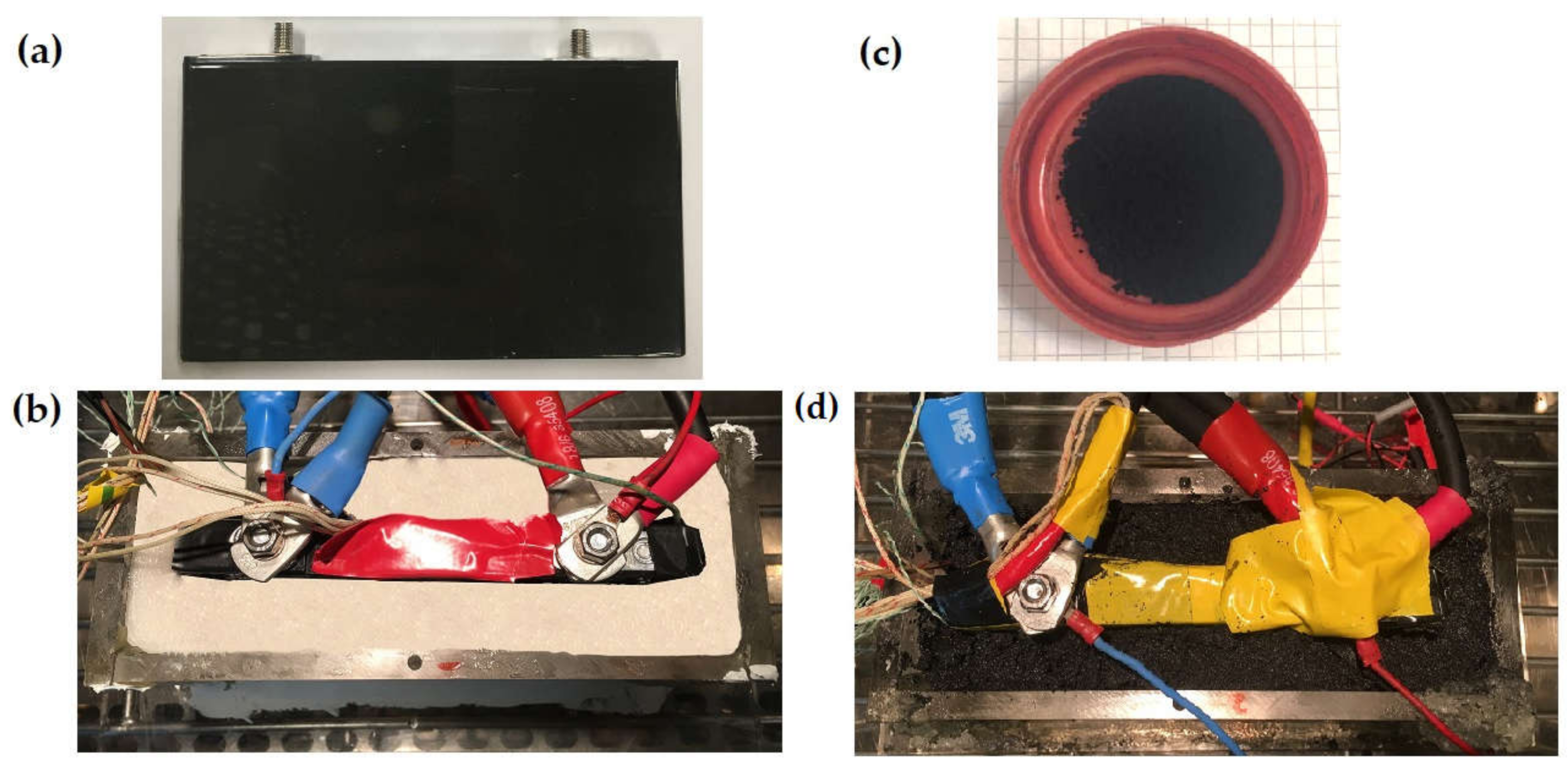
2.1. Samples

The cell sample used in this paper was a fresh prismatic 2300 F lithium-ion capacitor (LiC). The specifications of the LiC are listed in Table 1. For the test, the LiC was charged and discharged for 1400 s using a continuous 150 A current rate, which is considered a high-power driving cycle. The applied test was a constant current (CC) charge and discharge pattern, in which the cell was charged under a CC of 150 A until the voltage reaches the maximum charge cut-off voltage of 3.8 V. Then, the cell was discharged under a CC of 150 A until the voltage reached the minimum cut-off voltage of 2.2 V. Each full charge and discharge pattern tool 36 s. The LiC cell is depicted in Figure 1a.
The phase-change material (PCM) sample was a paraffin-based wax with a melting domain of 35–42 °C, with a maximum operating temperature of 210 °C. The thermal conductivity of the PCM used was 0.25 W/m∙K and 0.4 W/m∙K for the solid phase and liquid phase, respectively, which is considered a very low conductivity. Therefore, an added material such as graphite should be mixed with the pure paraffin PCM to increase its thermal properties. The impact of the thermal conductivity of the PCM is vital for the heat dissipation performance of the proposed TMS. The pure PCM TMS is shown in Figure 1b. The mixed PCM-Graphite (PCM/G) had an enhanced thermal conductivity of 0.5 W/m∙K for the solid phase and 1 W/m∙K for the liquid phase. The mixed PCM/G was a solid black powder that was prepared using a blender. The pure PCM and the PCM/G specifications are listed in Table 2. The PCM/G is exhibited in Figure 1c.
The container of the PCM and LiC was made of Polyvinyl Chloride (PVC) with thermal conductivity of 0.19 W/m∙K. The cell was placed inside the middle of the PVC container. The thickness of the PVC container walls was 7 mm. The thickness of the poured PCM inside the PVC container was 10 mm from each side.

2.2. Experimental Design and Test Bench

The experimental test bench is depicted in Figure 2a. The entire test was performed in a climate chamber with a constantly controlled temperature of 23 °C. The positive and negative tabs of the LiC cell were connected to the battery cycler by a voltage/current cables connection. The battery tester was responsible for applying a 150 A charge/discharge current rate for 1400 s. Due to the attached K-type thermocouples on the cell surface, a data logger was responsible for temperature monitoring. The position of the thermocouple was selected based on the hottest point in the cell. This hot spot was chosen based on our previous experience published in [45,46], which will not be explained here to avoid redundancy. The data logger recorded the temperature and transferred it to the monitoring computer.
Figure 2b shows the applied current and voltage in the LiC cell, in which the applied charge and discharge current was ±150 A, with the cut-off voltages of 2.2 V and 3.8 V. Figure 2c depicts the first charge and discharge slice of the whole profile to show how the cell is charged and discharged under a high current rate. Two tests with pure PCM and PCM/G were conducted to understand the difference between these two cooling systems. The case without PCM was also tested for comparison. The thermophysical properties of the LiC cell regarding its various domains are listed in Table 3. These different domains include the positive tab, the negative tab, and the electrode domain.

3. Results and Discussion

3.1. Theories on Heat Generation of the LiC Cell

The numerical analysis model of the 2300 F LiC cell is introduced in this section. First, the model should be solved without any TMS under natural convection, and then the PCM is poured around the cell to maintain its temperature. Therefore, the influence of the proposed TMS using pure PCM and PCM/G can be compared with natural convection to understand its effectiveness. The heat generation of the LiC cell is due to internal and external heat sources. The internal heat source is the result of the chemical reactions inside the 2300 F LiC. On the other hand, the negative and positive tabs cause the external heat source. The governing equations are solved in this context for both the internal and external heat sources, which can be used as an input for the computational fluid dynamics model using a 150 A applied current over 1400 s.
The equation of energy balance should first be explained as the main equation for the power loss of the LiC cell under natural convection [46]:
ρ C p d T d t   =   [ λ x 2 T x 2   +   λ y 2 T y 2   +   λ z 2 T z 2 ]   +   q ˙     q c o n v
where ρ [kg/m3] denotes the LiC’s density and Cp [J/kg∙K] represents the LiC’s heat capacity. Additionally, T [K] is the LiC’s temperature, λ [W/m∙K] is the LiC’s thermal conductivity, and q ˙ [W/m3] denotes the LiC’s heat generation.
Due to the non-uniform heat generation of the LiC cell, the cell domain heat source and tab domain heat source should be considered for such a cell [47]:
q ˙ c e l l   =   q ˙ i r r   +   q ˙ r e v   =   I   ( U     V )     I   T   U T
q ˙ t a b   =   R   I 2 V t a b
R   =   ρ   l S
q ˙ c e l l , q ˙ t a b , q ˙ i r r , and q ˙ r e v represent the cell, tab, irreversible, and reversible heat generation. In addition, ρ [Ωm] denotes the resistivity, l [m] denotes the length, and S [m2] represents the cross-sectional area.
The heat is transferred from the cell to the ambient due to the convective heat transfer ( h [W/m2]) [48]:
q c o n v   =   h . S   ( T a m b     T )
where T a m b [K] and T [K] are the ambient and cell temperatures.

3.2. Theories on Thermal Behavior of PCM

The phase change is the main phenomenon to absorb the generated heat from the LiC. When the PCM absorbs heat and its temperature is close to the phase-change temperature, a phase transition from a solid to a liquid occurs [49]. During this phase, by melting the PCM, a large amount of heat is absorbed by the PCM thanks to its high latent heat of fusion, which is 220 kJ/kg.
When the temperature of the LiC is below the phase transition zone, the absorbed heat by the PCM ( Q P C M ) is calculated as [50]:
Q P C M   =   C P C M     s m P C M ( T P C M     T i )
where C P C M     s , m P C M , T P C M , and T i denote the specific heat capacity of the PCM in the solid zone, the mass of the PCM, the temperature of the PCM, and the initial temperature of the PCM, respectively.
When the temperature of the LiC reaches the melting temperature, Q P C M is calculated as:
Q P C M   =   C P C M     s m P C M ( T s     T i )   +   C P C M m P C M ( T P C M     T s )
where T s and C P C M represent the phase-change temperature from the solid phase to the mushy zone and PCM’s specific heat capacity, respectively.
When the temperature of the LiC is above the maximum temperature of the mushy zone, Q P C M can be expressed as:
Q P C M   =   C P C M     s m P C M ( T m e l t     T i )   +   L m P C M   +   C P C M     l m P C M ( T P C M     T m e l t )
where T m e l t , L , and C P C M     l denote the PCM’s melting temperature, the PCM’s latent heat of fusion, and the PCM’s specific heat capacity in the liquid zone.
According to what has been mentioned above, the heat absorbed by the PCM is divided into three scenarios considering the temperature of the LiC [51].

3.3. Experimental Results and Analysis

The experimental results have been demonstrated in this section, for which three different case studies have been defined, including the thermal behavior of the LiC under natural convection when the PCM is not charged into the PVC container, the thermal behavior of the LiC when pure PCM has been used as the cooling system, and the thermal behavior of the LiC when graphite has been mixed with the PCM (PCM/G) to enhance its thermal conductivity. Moreover, the impact of various thicknesses has been studied for the PCM/G to evaluate the most efficient thickness that can control the maximum temperature of the LiC.

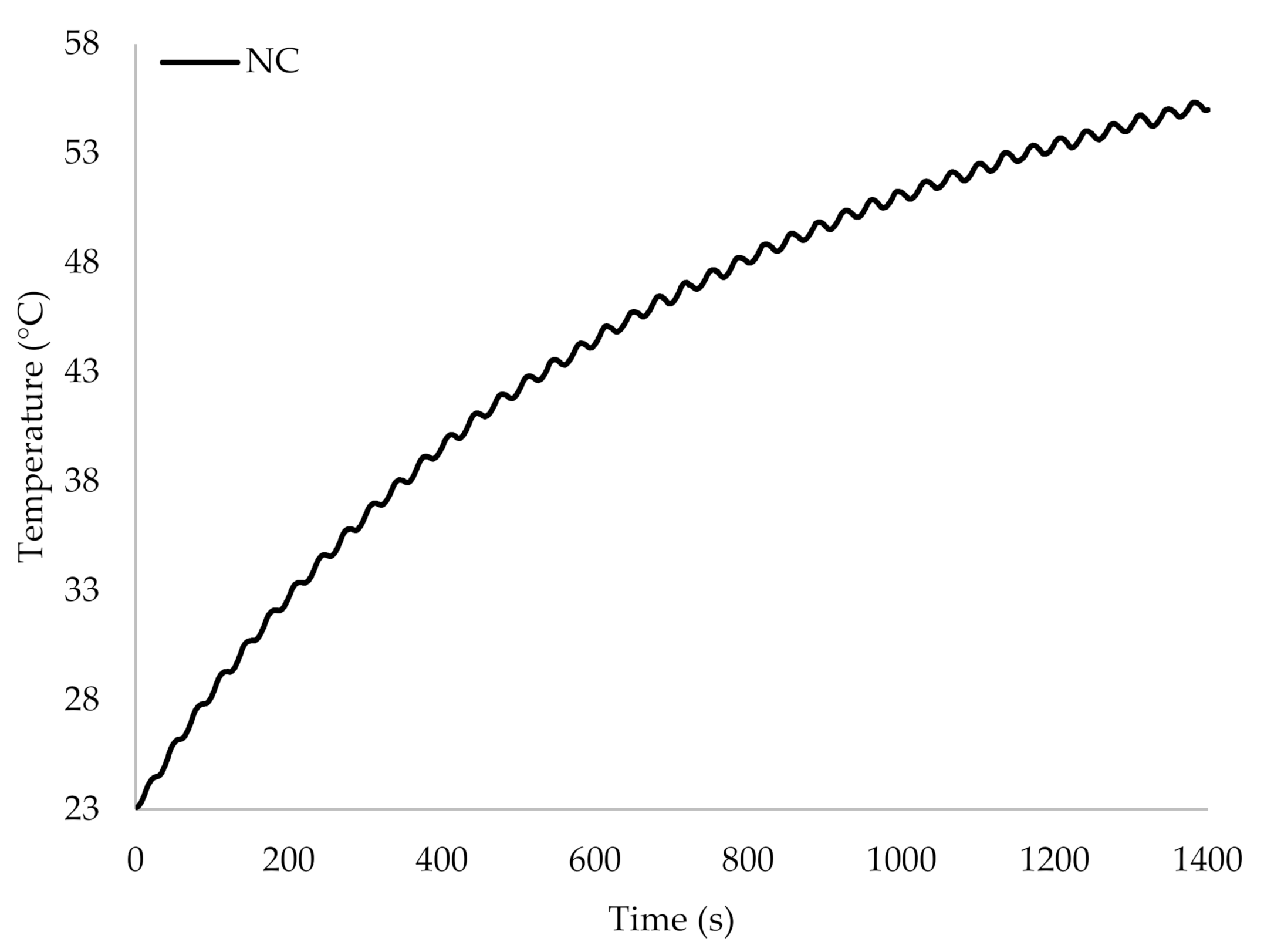
3.3.1. Thermal Behavior of the LiC under Natural Convection

The first case study to understand the thermal behavior of the LiC is natural convection, which is caused by the buoyancy effect. This method is considered a passive cooling system with the advantages of zero power consumption, low cost, and simple structure [52]. In this context, the temperature of the LiC is monitored by the data logger under the 150 A continuous current rate. This current rate is applied to charge and discharge the cell more than 38 times without any rest in between over 1400 s. Such a dynamic driving profile generates too much heat, at around 83 kW/m3. The heat transfer coefficient of the test bench is approximately 7 W/m2∙K. When the heat transfer coefficient is below 25 W/m2∙K, the system can be considered to be under natural convection [53]. Figure 3 depicts the temperature evolution of the LiC cell under natural convection. The initial temperature is almost 23 °C, while the maximum temperature exceeds 55 °C, which is very harmful for the cell’s lifetime [54]. Moreover, thermal runaway is inevitable if the continuous charging and discharging continues [55]. Therefore, a cooling system is required to reduce the temperature evolution of the cell.

3.3.2. Thermal Behavior of the LiC When Using Pure PCM

PCM TMS is a common method for cooling batteries due to its simplicity, low cost, and zero power consumption. Moreover, the performance of this method is good when the environment heat transfer coefficient is relatively high. The PCM TMS is classified as a passive cooling system since it does not require any external power source to start operation. Figure 4 shows the temperature evolution of the LiC cell when PCM TMS is employed to cool it down. As is evident, the maximum temperature of the LiC is decreased from 55.3 °C to 40.2 °C, which shows a 27.3% temperature reduction compared to the natural convection case study. This performance is due to the high latent heat of fusion of the PCM that can absorb high amounts of heat. Therefore, this type of paraffin-based PCM can keep the temperature of the LiC cell at a constant temperature for a specific time interval. However, this absorbed heat cannot be rejected due to the low thermal conductivity of the pure paraffin PCM. Its thermal conductivity is approximately 0.25 W/m∙K for the solid phase and approximately 0.4 W/m∙K for the liquid phase. In this regard, an additional material should be added to the PCM to increase its thermal properties for heat rejection to the ambient.

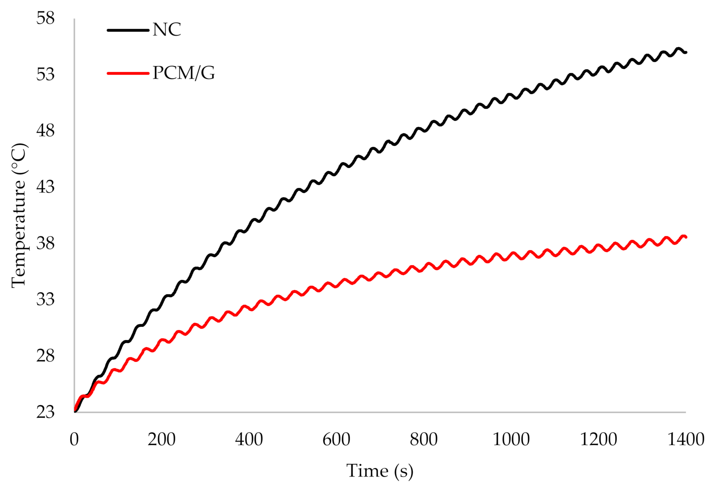
3.3.3. Thermal Behavior of the LiC When Using PCM/G

Since pure PCM has the disadvantage of low thermal conductivity, composite materials should compensate for this drawback. Graphite is known as a high-thermal conductive material that can enhance the thermal properties of pure PCM. This method of mixing the PCM with graphite would also increase the thermal performance of the TMS to reduce the maximum temperature of the LiC cell. The PCM–graphite mixture was constructed and poured into the PVC container to be in direct contact with the surface of the LiC cell. Figure 5 depicts the temperature evolution of the LiC cell under the 150 A current rate when the PCM/G has been used as the TMS. It can be seen that the maximum temperature of the LiC is reduced from 55.3 °C (natural convection) to 38.5 °C, which is a 30.4% temperature reduction compared to natural convection.

3.3.4. Comparison of the Pure PCM with the PCM/G

The maximum temperature of the LiC cell for three different case studies has been investigated, for which it was 55.3 °C for natural convection, 40.2 °C for pure PCM cooling, and 38.5 for the PCM/G composite. By looking at Figure 6, a 4% temperature reduction can be seen when using PCM/G compared to the pure paraffin PCM. The maximum temperature of the LiC is reduced from 40.2 °C to 38.5 °C, which shows a 1.7 °C temperature reduction.

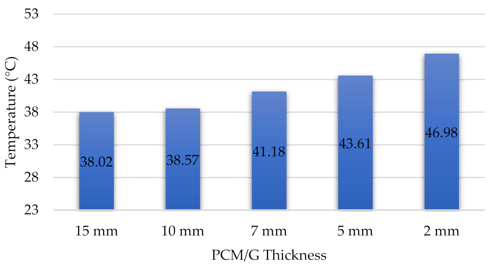
3.3.5. The Influence of PCM/G Thickness of the LiC Temperature

An investigation of the thickness is vital for optimizing the cost, weight, and volume performance indicators. The main aim would be the optimal PCM thickness that can control the temperature evolution of the LiC cell while minimizing the performance indicators. In such a respect, various PCM thicknesses have been used to study the system’s thermal behavior considering the dedicated thickness. The employed thicknesses in this regard are 15 mm, 10 mm, 7 mm, 5 mm, and 2 mm. The inserted fraction of graphite mixed with the PCM is the same in all the thicknesses. The final PCM/G’s weight and volume follow the used material’s characteristics considering the dimensions and the density. The maximum temperature at the end of the cycling test is based on the temperature evolution that occurred over 1400 s.
Figure 7 exhibits the results of the tested system after 1400 s concerning various applied PCM/G thicknesses. As is apparent, by increasing the PCM/G thickness, the thermal performance of the proposed TMS is enhanced, and the maximum temperature of the LiC cell is reduced. However, the temperature reduction is no longer attractive for a thickness of more than 10 mm since by increasing the thickness by5 mm, only a 0.55 °C reduction can be seen. Based on the results, the maximum temperature of the LiC cell after 1400 s for a thickness of 15 mm is 38.02 °C, while for a thickness of 10 mm, the maximum temperature reaches 38.57 °C. Therefore, for a PCM/G thickness of more than 10 mm, the temperature reduction is no longer attractive, considering the PCM/G weight increase of 50%.
On the other hand, decreasing the thickness leads to an increase in the maximum temperature of the LiC cell. As can be seen, by reducing the thickness from 10 mm to 7 mm, the maximum temperature of the LiC cell increases from 38.57 °C to 41.18 °C. Additionally, the thicknesses of 5 mm and 2 mm are not good candidates as the maximum temperature reaches 43.61 °C and 46.98 °C, respectively. As is recommended by the manufacturer of LiC cells, the maximum safe operating temperature of the LiC should be below 40 °C. Therefore, the optimal thickness of 10 mm is rather robust at controlling the temperature evolution of the LiC cell and optimizing the performance indicators of weight, volume, and cost.

4. Conclusions

A thermal management method for the LiC cell was investigated using a composite of graphite and PCM (PCM/G) to enhance the cooling performance of the paraffin-based PCM. The composite PCM/G addresses the main drawback of the PCMs, that is, the low thermal properties, specifically low thermal conductivity. Generally, paraffin-based PCM has a high latent heat of fusion, meaning that a high amount of the heat generated by the LiC can be absorbed and stored in the PCM. However, this stored heat cannot be released to the ambient due to low thermal conductivity. A composite such as PCM/G helps reject the absorbed heat from the PCM. In this context, significant findings can be expressed as follows:
  • The LiC cell was charged/discharged for 1400 s under a high current rate of 150 A without any rest.
  • When the cell was under natural convection, the maximum temperature exceeded 55 °C, which is very harmful for the lifetime of the cell.
  • Using the pure paraffin PCM, the maximum temperature of the LiC was decreased from 55.3 °C to 40.2 °C, which showed a 27.3% temperature reduction compared to the natural convection case study.
  • Using the PCM/G composite, the maximum temperature of the LiC was reduced from 55.3 °C (natural convection) to 38.5 °C, which is a 30.4% temperature reduction compared to natural convection.
  • A 4% temperature reduction was observed using PCM/G instead of the pure paraffin PCM.
  • Different PCM/G thicknesses were investigated to determine the maximum temperature of the LiC, and temperatures of 38.02 °C, 38.57 °C, 41.18 °C, 43.61 °C, and 46.98 °C were reached for the thicknesses of 15 mm, 10 mm, 7 mm, 5 mm, and 2 mm, respectively. In this context, a thickness of 10 mm is rather optimal considering cost, weight, volume, and temperature reduction.

Author Contributions

Conceptualization, methodology, formal analysis, investigation, writing—original journal draft, D.K.; writing, review and editing, H.B.; supervision, review and editing, J.V.M. and M.B. All authors have read and agreed to the published version of the manuscript.

Funding

This research received no external funding.

Institutional Review Board Statement

Not applicable.

Informed Consent Statement

Not applicable.

Data Availability Statement

Not applicable.

Acknowledgments

This research is based on work supported by JSR Micro NV. In addition, we acknowledge Flanders Make for supporting the MOBI group.

Conflicts of Interest

The authors declare no conflict of interest.

References

  1. Berckmans, G.; Jaguemont, J.; Soltani, M.; Samba, A.; Boninsegna, M.; Omar, N.; Hegazy, O.; Van Mierlo, J.; Ronsmans, J. Lithium-Ion Capacitor—Optimization of Thermal Management from Cell to Module Level; IEEE: Hangzhou, China, 2016; p. 5. [Google Scholar]
  2. Wu, W.; Yang, X.; Zhang, G.; Chen, K.; Wang, S. Experimental investigation on the thermal performance of heat pipe-assisted phase change material based battery thermal management system. Energy Convers. Manag. 2017, 138, 486–492. [Google Scholar] [CrossRef]
  3. Berckmans, G.; Samba, A.; Omar, N.; Ronsmans, J.; Soltani, M.; Firouz, Y.; Van Den Bossche, P.; Van Mierlo, J. Lithium ion capacitor—Optimization of thermal management from cell to module level. In Proceedings of the 2016 IEEE Vehicle Power and Propulsion Conference (VPPC), Hangzhou, China, 17–20 October 2016; pp. 1–6. [Google Scholar] [CrossRef]
  4. Hosen, S.; Karimi, D.; Kalogiannis, T.; Pirooz, A.; Jaguemont, J.; Berecibar, M.; Van Mierlo, J. Electro-aging model development of nickel-manganese-cobalt lithium-ion technology validated with light and heavy-duty real-life profiles. J. Energy Storage 2020, 28, 101265. [Google Scholar] [CrossRef]
  5. Khaleghi, S.; Hosen, S.; Karimi, D.; Behi, H.; Beheshti, S.H.; Van Mierlo, J.; Berecibar, M. Developing an online data-driven approach for prognostics and health management of lithium-ion batteries. Appl. Energy 2022, 308, 118348. [Google Scholar] [CrossRef]
  6. Behi, H.; Karimi, D.; Jaguemont, J.; Gandoman, F.H.; Kalogiannis, T.; Berecibar, M.; Van Mierlo, J. Novel thermal management methods to improve the performance of the Li-ion batteries in high discharge current applications. Energy 2021, 224, 120165. [Google Scholar] [CrossRef]
  7. Soltani, M.; Ronsmans, J.; Kakihara, S.; Jaguemont, J.; van den Bossche, P.; Van Mierlo, J.; Omar, N. Hybrid Battery/Lithium-Ion Capacitor Energy Storage System for a Pure Electric Bus for an Urban Transportation Application. Appl. Sci. 2018, 8, 1176. [Google Scholar] [CrossRef] [Green Version]
  8. Soltani, M.; Beheshti, S.H. A comprehensive review of lithium ion capacitor: Development, modelling, thermal management and applications. J. Energy Storage 2021, 34, 102019. [Google Scholar] [CrossRef]
  9. Soltani, M.; De Sutter, L.; Ronsmans, J.; van Mierlo, J. A high current electro-thermal model for lithium-ion capacitor technology in a wide temperature range. J. Energy Storage 2020, 31, 101624. [Google Scholar] [CrossRef]
  10. Soltani, M.; Ronsmans, J.; Van Mierlo, J. Cycle life and calendar life model for lithium-ion capacitor technology in a wide temperature range. J. Energy Storage 2020, 31, 101659. [Google Scholar] [CrossRef]
  11. Hosen, S.; Kalogiannis, T.; Youssef, R.; Karimi, D.; Behi, H.; Jin, L.; Van Mierlo, J.; Berecibar, M. Twin-model framework development for a comprehensive battery lifetime prediction validated with a realistic driving profile. Energy Sci. Eng. 2021, 9, 2191–2201. [Google Scholar] [CrossRef]
  12. Karimi, D.; Behi, H.; Hosen, S.; Jaguemont, J.; Berecibar, M.; Van Mierlo, J. A compact and optimized liquid-cooled thermal management system for high power lithium-ion capacitors. Appl. Therm. Eng. 2021, 185, 116449. [Google Scholar] [CrossRef]
  13. Zhao, J.; Rao, Z.; Huo, Y.; Liu, X.; Li, Y. Thermal management of cylindrical power battery module for extending the life of new energy electric vehicles. Appl. Therm. Eng. 2015, 85, 33–43. [Google Scholar] [CrossRef]
  14. Karimi, D.; Behi, H.; Akbarzadeh, M.; Van Mierlo, J.; Berecibar, M. Holistic 1D Electro-Thermal Model Coupled to 3D Thermal Model for Hybrid Passive Cooling System Analysis in Electric Vehicles. Energies 2021, 14, 5924. [Google Scholar] [CrossRef]
  15. Karimi, D.; Behi, H.; Jaguemont, J.; Berecibar, M.; Van Mierlo, J. Optimized air-cooling thermal management system for high power lithium-ion capacitors. Energy Perspect. 2020, 1, 93–105. [Google Scholar]
  16. Karimi, D.; Behi, H.; Jaguemont, J.; Berecibar, M.; Van Mierlo, J. A refrigerant-based thermal management system for a fast charging process for lithium-ion batteries. In Proceedings of the International Conference on Renewable Energy Systems and Environmental Engineering, Brussels, Belgium, 17–18 December 2020; Global Publisher: Hershey, PA, USA, 2020; pp. 1–6. [Google Scholar]
  17. Karimi, D.; Behi, H.; Jaguemont, J.; El Baghdadi, M.; Van Mierlo, J.; Hegazy, O. Thermal Concept Design of MOSFET Power Modules in Inverter Subsystems for Electric Vehicles. In Proceedings of the 2019 9th International Conference on Power and Energy Systems (ICPES), Perth, WA, Australia, 10–12 December 2019. [Google Scholar] [CrossRef]
  18. Möller, S.; Karimi, D.; Vanegas, O.; El Baghdadi, M.; Kospach, A.; Lis, A.; Hegazy, O.; Abart, C.; Offenbach, Â.B.Â. Application Considerations for Double Sided Cooled Modules in Automotive Environment. 2020. Available online: https://ieeexplore.ieee.org/document/9097721 (accessed on 16 November 2020).
  19. Karimi, D.; Behi, H.; Jaguemont, J.; Berecibar, M.; Van Mierlo, J. Investigation of extruded heat sink assisted air cooling system for lithium-ion capacitor batteries. In Proceedings of the International Conference on Renewable Energy Systems and Environmental Engineering, Brussels, Belgium, 17–18 December 2020; Global Publisher: Hershey, PA, USA, 2020; pp. 1–6. [Google Scholar]
  20. Karimi, D.; Hosen, S.; Behi, H.; Khaleghi, S.; Akbarzadeh, M.; Van Mierlo, J.; Berecibar, M. A hybrid thermal management system for high power lithium-ion capacitors combining heat pipe with phase change materials. Heliyon 2021, 7, e07773. [Google Scholar] [CrossRef]
  21. Jaguemont, J.; Karimi, D.; Van Mierlo, J. Investigation of a Passive Thermal Management System for Lithium-Ion Capacitors. IEEE Trans. Veh. Technol. 2019, 68, 10518–10524. [Google Scholar] [CrossRef]
  22. Behi, H.; Karimi, D.; Youssef, R.; Patil, M.S.; Van Mierlo, J.; Berecibar, M. Comprehensive Passive Thermal Management Systems for Electric Vehicles. Energies 2021, 14, 3881. [Google Scholar] [CrossRef]
  23. Behi, H.; Kalogiannis, T.; Patil, M.S.; Van Mierlo, J.; Berecibar, M. A New Concept of Air Cooling and Heat Pipe for Electric Vehicles in Fast Discharging. Energies 2021, 14, 6477. [Google Scholar] [CrossRef]
  24. Akbarzadeh, M.; Kalogiannis, T.; Jaguemont, J.; Jin, L.; Behi, H.; Karimi, D.; Beheshti, H.; Van Mierlo, J.; Berecibar, M. A comparative study between air cooling and liquid cooling thermal management systems for a high-energy lithium-ion battery module. Appl. Therm. Eng. 2021, 198, 117503. [Google Scholar] [CrossRef]
  25. Behi, H.; Karimi, D.; Jaguemont, J.; Gandoman, F.H.; Khaleghi, S.; Van Mierlo, J.; Berecibar, M. Aluminum Heat Sink Assisted Air-Cooling Thermal Management System for High Current Applications in Electric Vehicles. In Proceedings of the 2020 AEIT International Conference of Electrical and Electronic Technologies for Automotive (AEIT AUTOMOTIVE), Turin, Italy, 18–20 November 2020. [Google Scholar]
  26. Behi, H.; Karimi, D.; Jaguemont, J.; Berecibar, M.; Van Mierlo, J. Experimental study on cooling performance of flat heat pipe for lithium-ion battery at various inclination angels. Energy Perspect. 2020, 1, 77–92. [Google Scholar]
  27. Behi, H.; Behi, M.; Ghanbarpour, A.; Karimi, D.; Azad, A.; Ghanbarpour, M.; Behnia, M. Enhancement of the Thermal Energy Storage Using Heat-Pipe-Assisted Phase Change Material. Energies 2021, 14, 6176. [Google Scholar] [CrossRef]
  28. Karimi, D.; Jaguemont, J.; Behi, H.; Berecibar, M.; Van Den Bossche, P.; Van Mierlo, J. Passive cooling based battery thermal management using phase change materials for electric vehicles. In Proceedings of the EventEVS33 International Electric Vehicle Symposium, Portland, OR, USA, 14–17 June 2020; pp. 1–12. [Google Scholar]
  29. Karimi, D.; Behi, H.; Jaguemont, J.; Sokkeh, M.A.; Kalogiannis, T.; Hosen, S.; Berecibar, M.; Van Mierlo, J. Thermal performance enhancement of phase change material using aluminum-mesh grid foil for lithium-capacitor modules. J. Energy Storage 2020, 30, 101508. [Google Scholar] [CrossRef]
  30. Ambekar, S.; Rath, P.; Bhattacharya, A. A novel PCM and TCE based thermal management of battery module. Therm. Sci. Eng. Prog. 2022, 29, 101196. [Google Scholar] [CrossRef]
  31. Safdari, M.; Ahmadi, R.; Sadeghzadeh, S. Numerical investigation on PCM encapsulation shape used in the passive-active battery thermal management. Energy 2020, 193, 116840. [Google Scholar] [CrossRef]
  32. Ling, Z.; Li, S.; Cai, C.; Lin, S.; Fang, X.; Zhang, Z. Battery thermal management based on multiscale encapsulated inorganic phase change material of high stability. Appl. Therm. Eng. 2021, 193, 117002. [Google Scholar] [CrossRef]
  33. Zhang, H.; Wu, X.; Wu, Q.; Xu, S. Experimental investigation of thermal performance of large-sized battery module using hybrid PCM and bottom liquid cooling configuration. Appl. Therm. Eng. 2019, 159, 113968. [Google Scholar] [CrossRef]
  34. El Idi, M.M.; Karkri, M.; Tankari, M.A. A passive thermal management system of Li-ion batteries using PCM composites: Experimental and numerical investigations. Int. J. Heat Mass Transf. 2021, 169, 120894. [Google Scholar] [CrossRef]
  35. Putra, N.; Sandi, A.F.; Ariantara, B.; Abdullah, N.; Mahlia, T.M.I. Performance of beeswax phase change material (PCM) and heat pipe as passive battery cooling system for electric vehicles. Case Stud. Therm. Eng. 2020, 21, 100655. [Google Scholar] [CrossRef]
  36. Gandoman, F.H.; Behi, H.; Berecibar, M.; Jaguemont, J.; Aleem, S.H.A.; Behi, M.; Van Mierlo, J. Chapter 16—Reliability evaluation of Li-ion batteries for electric vehicles applications from the thermal perspectives. In Uncertainties in Modern Power Systems; Zobaa, A.F., Abdel Aleem, S.H.E., Eds.; Academic Press: Cambridge, MA, USA, 2021; pp. 563–587. [Google Scholar] [CrossRef]
  37. Behi, H. Experimental and Numerical Study on Heat Pipe Assisted PCM Storage System. Master’s Thesis, School of Industrial Engineering and Management, Stockholm, Sweden, 2015. [Google Scholar]
  38. Behi, H.; Karimi, D.; Gandoman, F.H.; Akbarzadeh, M.; Khaleghi, S.; Kalogiannis, T.; Hosen, S.; Jaguemont, J.; Van Mierlo, J.; Berecibar, M. PCM assisted heat pipe cooling system for the thermal management of an LTO cell for high-current profiles. Case Stud. Therm. Eng. 2021, 25, 100920. [Google Scholar] [CrossRef]
  39. Wang, S.; Xing, Y.; Hao, Z.; Yin, J.; Hou, X.; Wang, Z. Experimental study on the thermal performance of PCMs based heat sink using higher alcohol/graphite foam. Appl. Therm. Eng. 2021, 198, 117452. [Google Scholar] [CrossRef]
  40. Yazici, M.; Saglam, M.; Aydin, O.; Avci, M. Thermal energy storage performance of PCM/graphite matrix composite in a tube-in-shell geometry. Therm. Sci. Eng. Prog. 2021, 23, 100915. [Google Scholar] [CrossRef]
  41. Chen, X.; Zhou, F.; Yang, W.; Gui, Y.; Zhang, Y. A hybrid thermal management system with liquid cooling and composite phase change materials containing various expanded graphite contents for cylindrical lithium-ion batteries. Appl. Therm. Eng. 2022, 200, 117702. [Google Scholar] [CrossRef]
  42. Zou, D.; Liu, X.; He, R.; Zhu, S.; Bao, J.; Guo, J.; Hu, Z.; Wang, B. Preparation of a novel composite phase change material (PCM) and its locally enhanced heat transfer for power battery module. Energy Convers. Manag. 2019, 180, 1196–1202. [Google Scholar] [CrossRef]
  43. Lin, X.; Zhang, X.; Liu, L.; Liang, J.; Liu, W. Polymer/expanded graphite-based flexible phase change material with high thermal conductivity for battery thermal management. J. Clean. Prod. 2022, 331, 130014. [Google Scholar] [CrossRef]
  44. Wu, W.; Wu, W.; Wang, S. Thermal optimization of composite PCM based large-format lithium-ion battery modules under extreme operating conditions. Energy Convers. Manag. 2017, 153, 22–33. [Google Scholar] [CrossRef]
  45. Wang, X.; Li, B.; Qu, Z.; Zhang, J.; Jin, Z. Effects of graphite microstructure evolution on the anisotropic thermal conductivity of expanded graphite/paraffin phase change materials and their thermal energy storage performance. Int. J. Heat Mass Transf. 2020, 155, 119853. [Google Scholar] [CrossRef]
  46. Soltani, M. Advanced Modelling Techniques for Lithium-Ion Capacitor Technology. Ph.D. Thesis, Vrije Universiteit Brussel, Brussels, Belgium, 2020. [Google Scholar]
  47. Soltani, M.; Jaguemont, J.; Boninsegna, M.; Berckmans, G.; Abdel-monem, M. Thermal management system for a Lithium-ion Capacitor Module with air cooling strategy. In Proceedings of the International Electric Vehicle Symposium and Exhibition (EVS), Stuttgart, Germany, 9–11 October 2017; pp. 1–10. [Google Scholar]
  48. Shahid, S.; Agelin-Chaab, M. Analysis of Cooling Effectiveness and Temperature Uniformity in a Battery Pack for Cylindrical Batteries. Energies 2017, 10, 1157. [Google Scholar] [CrossRef] [Green Version]
  49. Behi, H.; Karimi, D.; Kalogiannis, T.; He, J.; Patil, M.S.; Muller, J.-D.; Haider, A.; Van Mierlo, J.; Berecibar, M. Advanced hybrid thermal management system for LTO battery module under fast charging. J. Case Stud. Therm. Eng. 2022, 33, 101938. [Google Scholar] [CrossRef]
  50. Liu, J.; Fan, Y.; Xie, Q. An experimental study on the thermal performance of mixed phase change materials-based battery cooling system. J. Energy Storage 2022, 46, 103839. [Google Scholar] [CrossRef]
  51. Jaguemont, J.; Van Mierlo, J. A comprehensive review of future thermal management systems for battery-electrified vehicles. J. Energy Storage 2020, 31, 101551. [Google Scholar] [CrossRef]
  52. Samimi, F.; Babapoor, A.; Azizi, M.; Karimi, G. Thermal management analysis of a Li-ion battery cell using phase change material loaded with carbon fibers. Energy 2016, 96, 355–371. [Google Scholar] [CrossRef]
  53. Kosky, P.; Balmer, R.; Keat, W.; Wise, G. Chapter 16 - Green Energy Engineering. In Exploring Engineering; Elsevier: Amsterdam, The Netherlands, 2013; pp. 339–356. [Google Scholar] [CrossRef]
  54. Karimi, D.; Khaleghi, S.; Behi, H.; Beheshti, H.; Hosen, S.; Akbarzadeh, M.; Van Mierlo, J.; Berecibar, M. Lithium-Ion Capacitor Lifetime Extension through an Optimal Thermal Management System for Smart Grid Applications. Energies 2021, 14, 2907. [Google Scholar] [CrossRef]
  55. Chen, Y.; Kang, Y.; Zhao, Y.; Wang, L.; Liu, J.; Li, Y.; Liang, Z.; He, X.; Li, X.; Tavajohi, N.; et al. A review of lithium-ion battery safety concerns: The issues, strategies, and testing standards. J. Energy Chem. 2021, 59, 83–99. [Google Scholar] [CrossRef]
Figure 1. (a) The prismatic 2300 F LiC cell; (b) the pure PCM TMS poured into the PVC container around the cell; (c) pure graphite (4% of the total weight); (d) the composite PCM/G TMS poured into the PVC container around the cell.
Energies 15 02515 g001
Figure 2. (a) Experimental test bench; (b) current and voltage profiles with 150 A charge and discharge cycles; (c) detailed profile for the first charge and discharge profile.
Energies 15 02515 g002
Figure 3. Temperature evolution of the LiC cell under 150 A current rate when there is no cooling system (under natural convection (NC)).
Energies 15 02515 g003
Figure 4. Temperature evolution of the LiC cell under 150 A current rate when the pure paraffin PCM is used as the cooling system. Natural convection (NC) is shown as well for comparison.
Energies 15 02515 g004
Figure 5. Temperature evolution of the LiC cell under 150 A current rate when the PCM/graphite (PCM/G) is used as the cooling system. Natural convection (NC) is shown for comparison.
Energies 15 02515 g005
Figure 6. Comparison of the temperature evolution for three different scenarios, including natural convection (NC), PCM cooling, and PCM/Graphite cooling under 150 A current rate.
Energies 15 02515 g006
Figure 7. Comparison of the temperature evolution for three different scenarios, including natural convection (NC), PCM cooling, and PCM/Graphite cooling under 150 A current rate.
Energies 15 02515 g007
Table 1. Specifications of the 2300 F LiC cell.
ParametersSpecification
Capacitance [F]2300
Cut-off Voltage [V]2.2–3.8
Weight [kg]0.335
Working Temperature [°C]−30 to +70
Table 2. The main features of the PCM and PCM/graphite.
ParametersPCMPCM/G
Melting area (°C)35–4235–42
Operating temperature (°C)210210
Thermal conductivity for the solid phase (W/m∙K)0.250.5
Thermal conductivity for the liquid phase (W/m∙K)0.41
Latent heat of fusion (kJ/kg)220210
Density of the solid phase (Kg/Lit)0.80.8
Density of the liquid phase (Kg/Lit)0.850.85
Specific heat capacity (J/kg∙K)25002500
Table 3. Specifications of various domains of 2300 F Lithium-ion capacitor.
Electrode DomainNegative TabPositive Tab
Density [kg/m3]162789602700
Thermal conductivityλy = λz = 5; λx = 0.36400238
Specific heat [J/kg∙K]1271385900
Publisher’s Note: MDPI stays neutral with regard to jurisdictional claims in published maps and institutional affiliations.

