Article

Permeability Modeling and Estimation of Hydrogen Loss through Polymer Sealing Liners in Underground Hydrogen Storage

Department of Geoengineering and Natural Resources Extraction, Faculty of Mining, Safety Engineering and Industrial Automation, Silesian University of Technology, Akademicka 2, 44-100 Gliwice, Poland
*
Author to whom correspondence should be addressed.
Energies 2022, 15(7), 2663; https://doi.org/10.3390/en15072663
Submission received: 27 February 2022 / Revised: 27 March 2022 / Accepted: 1 April 2022 / Published: 5 April 2022

Abstract

:
Fluctuations in renewable energy production, especially from solar and wind plants, can be solved by large-scale energy storage. One of the possibilities is storing energy in the form of hydrogen or methane–hydrogen blends. A viable alternative for storing hydrogen in salt caverns is Lined Rock Cavern (LRC) underground energy storage. One of the most significant challenges in LRC for hydrogen storage is sealing liners, which need to have satisfactory sealing and mechanical properties. An experimental study of hydrogen permeability of different kinds of polymers was conducted, followed by modeling of hydrogen permeability of these materials with different additives (graphite, halloysite and fly ash). Fillers in polymers can have an impact on the hydrogen permeability ratio and reduce the amount of polymer required to make a sealing liner in the reservoir. Results of this study show that hydrogen permeability coefficients of polymers and estimated hydrogen leakage through these materials are similar to the results of salt rock after the salt creep process. During 60 days of hydrogen storage in a tank of 1000 m2 inner surface, 1 cm thick sealing liner and gas pressure of 1.0 MPa, only approx. 1 m3 STP of hydrogen will diffuse from the reservoir. The study also carries out the modeling of the hydrogen permeability of materials, using the Maxwell model. The difference between experimental and model results is up to 17%, compared to the differences exceeding 30% in some other studies.

1. Introduction

Increasing renewable energy production will cause the increase of energy storage capacity demands. Fluctuations of energy production from photovoltaics and wind turbines can be solved with Power-to-Gas technologies, which convert excess energy into hydrogen using PEM electrolysis [1,2]. Hydrogen can then be converted into synthetic methane (syngas) in the methanation process. These technologies are already well-developed, including the connection with Carbon Capture and Utilization (CCU) as a carbon source for methanation [3,4,5]. Hydrogen can be utilized as pure gas or injected into a natural gas grid with limited concentrations, allowed by the tolerance of end-use devices [6,7]. However, the capacity of energy storage in a gas grid is very limited. Salt cavern storage facilities, capable of storing synthetic gas, methane or hydrogen exist [8,9], but are limited to places with favorable geological structures. Some geomechanic problems are also an issue [10]. Therefore, there is a need to seek alternative energy storage technologies. A promising underground storage technology is the Lined Rock Cavern (LRC). These kinds of caverns can be excavated as dedicated caverns or adapted from existing ones. Apart from the general geomechanical considerations, one of the most important concerns is the sealing efficiency of the inner liner of a gas tank. LRCs are successfully proven for natural gas storage. There are few examples of LRC storage in operation or for research purposes, such as the ones in Sweden, South Korea and Japan [11,12,13]. Since LRC tanks are isolated from surrounding rocks, they can be used for storage hydrogen or methane–hydrogen blends. Proper sealing is important because of the high mobility of hydrogen, as well as reactions with microorganisms in the presence of water [14,15]. Hard rock, where the LRC cavern is drilled, is only a base, which deals with the pressure and mechanics of the reservoir. It is not responsible for the isolation of the tank (which is the case in a salt cavern). In existing LRC reservoirs for natural gas, stainless steel is a common sealing liner material [11,12]. Nevertheless, it is essential to seek alternative sealing materials which are more economical, easily available and hydrogen corrosion resistant.
Depending on the sealing liner efficiency and its hydrogen permeability ratio, some hydrogen leakage from the reservoir will occur after a certain period of time. There are many experimental studies of gas permeability through different materials, which include, inter alia, the permeability of Helium (He), Carbon Dioxide (CO2), Nitrogen (N2), Oxygen (O2) and steam (H2O) through different synthetic polymers, such as HDPE, LDPE, PVC and polypropylene [16,17,18]. However, studies related to hydrogen (H2) permeability through polymers are very limited [19,20,21,22] and deal mostly with small hydrogen storage vessels [23,24] or permeability through o-rings [25]. Recent works performed by the authors study hydrogen permeability through epoxy resin, polyester resin and polyurethane [26,27].
Differences in gas permeability are an effect of changes in the gas migration path (tortuosity) and presence of dislocations in the crystal structure of polymers. The tortuosity effect will decrease the gas permeability, which is shown in Figure 1 [28].
Dislocation is a linear defect in the crystal structure of a material. It is a zone of tension which creates an easy path for gas elements to diffuse through. The presence of this kind of structure will increase the gas permeability process [26]. There is also lattice diffusion, which occurs in an ideal chemical structure. This kind of diffusion occurs in high temperatures (above Tammann’s temperature, approx. ½ of melting temperature [29]). Lattice diffusion of hydrogen can take place in two different mechanisms: interstitial mechanism and substitutional (vacancy) mechanism. Both mechanisms are shown in Figure 2. It is expected that additives such as graphite, halloysite and fly ash will decrease or increase the diffusion through epoxy resin, depending on what phenomena the added powder will cause or enhance.
This paper presents the results of simulations of hydrogen permeability through epoxy resin with different types of additives and different additive volumes, using the Maxwell model based on experimental results. It also simulates hydrogen leakage from a gas tank, using different sealing materials and storage parameters.

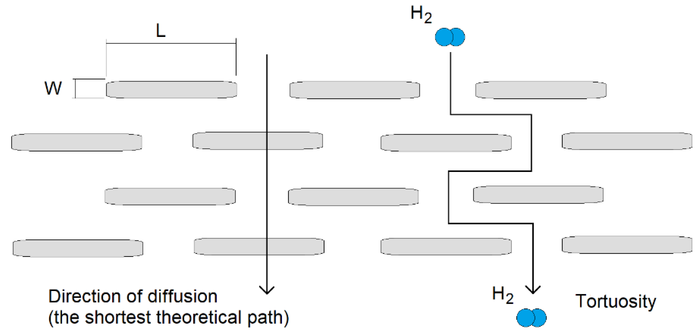
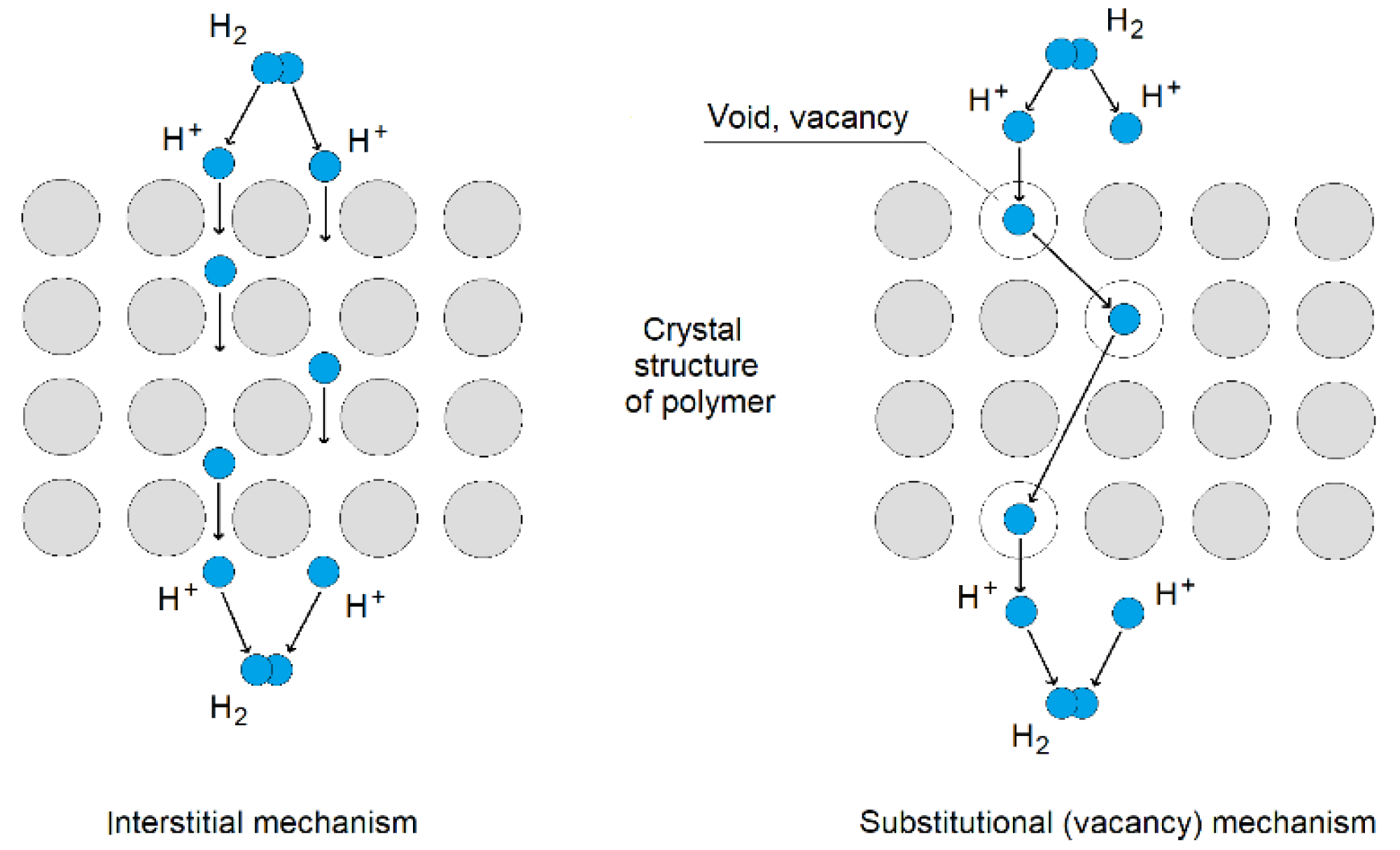
2. Methodology and Materials

Gas permeability of polymer composite is related to [30]:
  • Gas permeability coefficient (P) of pure polymer;
  • Type of powder additive;
  • Amount (volume) of powder additive;
  • Size of powder grains;
  • Dispersion of powder in the material.
There are many models describing mass and heat transfer through Mixed Matrix Membranes (MMMs), which are, inter alia, Maxwell, Bruggeman, Lewis–Nielsen, Pal, Cusser and Bharadwajl [31]. These models are based on the condition of the ideal morphology of a polymer, including ideal structure without defects, proper connections between phases (polymer-additive) and equal dispersion of powder additive. There are also some modifications of mentioned models, taking into account the non-ideal structure. However, for application in this work, they can be omitted. Mentioned models describe relative permeability (Pr) as a quotient of effective permeability of sample (Peff) and permeability of pure sample without additive (Pc). The general equation of these models is shown in Equation (1) [31].
P r = P e f f P c
where:
Pr—Relative permeability;
Peff—Effective permeability, permeability coefficient of polymer with additive, Barrer;
Pc—Continuous phase permeability, permeability of pure polymer without additive, Barrer.
Hydrogen permeability simulations through different epoxy resin samples were performed, using the Maxwell model, because of versatility and popularity of this particular model in that kind of application. This model does not take into account the shape and size of grains, nor additive dispersion in material. Volume of additive is also limited up to 20%. In the Maxwell model, permeability depends on:
  • Additive volume (Φ);
  • Permeability coefficient (Pc) of pure polymer (continuous phase);
  • Permeability coefficient (Pd) of additive (dispersed phase);
Maxwell model is shown in Equation (2) [31].
P r = P d + 2 P c 2 Φ P c P d P d + 2 P c + Φ P c P d
where:
Pr—Relative permeability;
Pc—Permeability coefficient of pure polymer (continuous phase);
Pd—Permeability coefficient of additive (dispersed phase);
Φ—Additive volume (0.0 to 0.2).
To calculate permeability coefficient of material with different additive volume, a permeability of dispersed phase (additive) Pd needs to be calculated (Equation (3)). It is possible to receive the experimental results of permeability coefficient of pure polymer (Pc-continuous phase) and effective permeability coefficient of the same polymer with known volume of additive (Peff), which leads to calculating relative permeability (Pr) using Equation (1).
P d = P c 2 2 Φ 2 P r P r Φ P r P r Φ 1 2 Φ
where:
Pr—Relative permeability;
Pc—Permeability coefficient of pure polymer (continuous phase);
Pd—Permeability coefficient of additive (dispersed phase);
Φ—Additive volume (0.0 to 0.2).
Using Equation (4) with received input data, there is now a possibility to change additive volume parameter (Φ), which leads to new relative permeability parameter (Pr′) related to new additive volume (Φ′).
P r = P d + 2 P c 2 Φ P c P d P d + 2 P c + Φ P c P d
where:
Pr’—Relative permeability for new additive volume (Φ′);
Pc—Permeability coefficient of pure polymer (continuous phase);
Pd—Permeability coefficient of additive (dispersed phase);
Φ′—New additive volume (0.0 to 0.2).
Constant parameter of continuous phase (Pc—permeability of pure polymer, which is not changing), allows to calculate new effective permeability (Peff’) parameter from Equation (5), which is the permeability coefficient (in Barrer unit) of polymer with new additive volume.
P e f f = P c P r
where:
Peff′—Effective permeability, permeability coefficient of polymer with new additive volume (Φ′), Barrer;
Pc—Continuous phase permeability, permeability of pure polymer without additive, Barrer;
Pr′—Relative permeability for new additive volume (Φ′).
Effective permeability (Peff) and permeability of continuous phase (Pc) were taken from experimental study, using Carrier Gas method, described in [26]. For each type of polymer and each type of additive, that kind of experimental work needs to be performed to obtain permeability coefficient of continuous phase and permeability coefficient of sample with known amount of additive (effective permeability), necessary for Maxwell model.
Hydrogen leakage through different sealing liners were estimated using Equation (6). Hydrogen leakage will depend on permeability coefficient of sealing material, inner area of tank, thickness of sealing liner, storage time and gas pressure.
V H 2 = P H 2 A t p l
where:
VH2—Volume of hydrogen diffusing through the sealing liner, cm3 STP;
PH2—Hydrogen permeability ratio, cm3 STP · cm · cm−2 · s−1 · cmHg−1;
A—Tank surface area, cm2;
t—Time, s;
p—Gas pressure, cmHg (1 bar = 75 cmHg);
l—Liner thickness, cm.
Samples taken into investigations in this work were made of commercial Epidian 5 epoxy resin with Z1 hardener. A pure sample, and samples with amorphous graphite, grinded halloysite and sieved fly ash with different volume ratios were investigated. Maxwell model for each type of epoxy sample (with graphite, halloysite and fly ash) was based on 5% additive volume. Rest of the samples were investigated to compare results with the permeabilities obtained from Maxwell equations. Details of investigated samples are shown in Table 1.

3. Maxwell Model Permeability

Model permeabilities were calculated using permeability of pure epoxy resin and the same kind of epoxy with additives (fly ash, amorphous graphite and grinded halloysite) of 5% volume. Results were obtained in Carrier Gas method. Results of the general model are shown in Table 2. Relative permeability (Pr) shows tendency and intensity of permeability changes. Values below 1 predict decrease of permeability with increase of additive volume. Values above 1 predict increase of permeability with increase of additive volume. The more the Pr value is different from 1 (below or above), the more rapid change of permeability will be.
Samples of epoxy with amorphous graphite (10% and 15% of volume) and fly ash (30% of volume) were investigated to compare model and experimental permeabilities. Results of Maxwell model are shown in Table 3. It has to be noted that content of additive in Maxwell model should not exceed 20%, while fly ash sample contains 30% volume of additive. However, permeability of fly ash sample is the same for 5% and 30% of additive, which is also confirmed with relative permeability (Pr) value, which is very close to 1 (Pr = 0.973). This is why the sample with 30% of fly ash additive was included into results.
Permeabilities received from Maxwell model and experimental work are shown in the plot in Figure 3.

4. Hydrogen Leakage Estimation

Hydrogen leakage estimations were carried out for different types of materials, including concretes, porous rocks, synthetic polymers and stainless steel. Permeability coefficients, used for estimation were investigated in the experimental work described in [26,32], using the Carrier Gas method and Steady–State Flow method. More samples were investigated later as well. Permeability coefficients used for estimation of hydrogen leakage are presented in Table 4. Measurement uncertainties were calculated separately for the Steady State Flow method and Carrier Gas method, because of differences in experimental setup and calculations. Relative uncertainty in the Steady–State method was 3.2%, and for the Carrier Gas method was 12.4%.
Some constant conditions were established, including tank size (volume and inner surface area), gas pressure and storage time. The volume of hydrogen leaks (in m3 in standard temperature and pressure) are shown in plots in Figure 4, Figure 5 and Figure 6. Figure 4 shows a comparison of all types of investigated materials used in underground gas storage. Figure 5 shows detailed hydrogen leaks in groups of synthetic polymers. There is also a salt rock, in which the hydrogen permeability coefficient is comparable to polymers. Figure 6 shows hydrogen leaks through the epoxy resin in different gas pressure conditions. Typical pressure in a salt cavern hydrogen reservoir varies from 4.5 to 15.0 MPa (45–150 bar) [8].
A comparison of hydrogen leakage based on model and experimental permeability is also presented in Figure 7. According to the results shown in Table 3, the difference between the model and experimental leakage is the same as the difference between the model and experimental hydrogen permeability coefficient of investigated samples, which is 16–17%. An exception is the case of the 5% filler, where experimental and model values are the same. The 5% filler sample was used as a basis for model calculations. Measurement error in experimental work for the Steady State Flow method (gas flow) was 3.2%, while for the Carrier Gas Method (gas diffusion) was 12.4%.

5. Discussion

Results show that the model predicting hydrogen diffusion used for this study is working properly. There is a tendency of permeability increase in the sample with graphite. On the contrary, the fly ash sample permeability should slightly decrease, according to model results. Experimental permeability was the same for samples with 5% and 30% of additive. However, relative permeability of the fly ash sample (Pr = 0,973) suggested only a slight decrease in permeability. It is in acceptable range of measurement uncertainty.
Differences between hydrogen permeability coefficients obtained from experimental work and the Maxwell model do not exceed 17%. These are satisfying results compared to differences reported in some studies regarding MMMs [34], where differences between model and experimental permeabilities exceed 30%.
Estimations of hydrogen leaks through different types of materials show significant differences between concrete, porous rocks, synthetic polymers, salt rock and stainless steel. Despite difference of six orders of magnitude between stainless steel (10−6 m3 STP of H2) and polymers (100 m3 STP of H2), this group of materials is still quite satisfactory as sealing liners for hydrogen. Taking into account the considered size of gas tank, gas pressure and storage time, some amount of hydrogen loss is still acceptable. Synthetic materials are economically justified compared to stainless steel. They also have good mechanical and physical properties, including low specific density, good flexibility and resistance to hydrogen corrosion. On the other hand, concrete-based materials and porous rocks (mudstone) are not an effective gas barrier. The range of hydrogen loss is approx. 106 to 104 m3 STP of H2 for concrete and rocks compared to 100 m3 STP of H2 for polymers. Plots show a significant gas loss through concrete and porous rock barriers, which is thousands of m3 STP more compared to polymers. Even short periods of storage will cause a significant loss in the volume of stored gas.
Hydrogen loss also depends on the pressure of stored gas. Since there is a linear dependence between the volume of diffused gas and pressure, hydrogen leaks will increase proportionally with increasing gas pressure in the reservoir. This dependence was also confirmed in authors’ recent experimental study [26].

6. Conclusions

Hydrogen permeability coefficients of polymers and estimated hydrogen leakage through these materials are similar to the results of salt rock after the salt creep process. Despite a few orders of magnitude higher permeability compared to stainless steel, hydrogen loss through polymer liners is still satisfactory. During 60 days of hydrogen storage in a tank with 1000 m2 of inner surface, with 1 cm thick sealing liner and gas pressure of 1.0 MPa, only approx. 1 m3 STP of hydrogen will diffuse from the reservoir. This kind of material can be successfully used as a substitution for stainless steel. On the other hand, concrete-based materials have significantly higher permeability, which leads to significant gas losses through these materials.
Thanks to the predicting models of hydrogen permeability, there is a possibility to analyze composites containing different kinds of additives with different volume ratios. Simulations of the hydrogen permeability coefficient (PH2) allow to check the theoretical hydrogen leakage through that kind of sealing liner and optimize the volume of additives in connection with acceptable hydrogen loss. Additives in polymers are desirable because they can reduce the amount of required polymer (for example epoxy resin), which leads to reducing the cost of the sealing liner.

Author Contributions

Conceptualization, D.G. and M.L.; methodology, D.G.; investigation, D.G.; data curation, D.G.; formal analysis, D.G. and M.L.; writing—original draft preparation, D.G.; writing—review and editing, M.L.; supervision, M.L.; funding acquisition, M.L. All authors have read and agreed to the published version of the manuscript.

Funding

This paper was supported by the Professor’s Grant funded by the Rector, Silesian University of Technology, grant no. 06/050/RGP/0083.

Informed Consent Statement

Not applicable.

Conflicts of Interest

The authors declare no conflict of interest.

References

  1. Denholm, P.; Ela, E.; Kirby, B.; Milligan, M. The Role of Energy Storage with Renewable Electricity Generation; Technical Report NREL/TP-6A2-47187; National Renewable Energy Laboratory: Golden, CO, USA, 2010. [Google Scholar]
  2. European Comission. Renewable Energy Progress Report; European Comission: Brussels, Belgium, 2019. [Google Scholar]
  3. Matos, C.R.; Carneiro, J.F.; Silva, P.P. Overview of Large-Scale Underground Energy Storage Technologies for Integration of Renewable Energies and Criteria for Reservoir Identification. J. Energy Storage 2018, 21, 241–258. [Google Scholar] [CrossRef]
  4. Apostolou, D.; Enevoldsen, P. The past, present and potential of hydrogen as a multifunctional storage application for wind power. Renew. Sustain. Energy Rev. 2019, 112, 917–929. [Google Scholar] [CrossRef]
  5. Bailera, M.; Lisbona, P.; Romeo, L.M.; Espatolero, S. Power to Gas projects review: Lab, pilot and demo plants for storing renewable energy and CO2. Renew. Sustain. Energy Rev. 2017, 69, 292–312. [Google Scholar] [CrossRef]
  6. Altfeld, K.; Pinchbeck, D. Admissible Hydrogen Concentrations in Natural Gas Systems. Gas Energy 2013, 2103, 1–2. [Google Scholar]
  7. Kuczyński, S.; Łaciak, M.; Olijnyk, A.; Szurlej, A.; Włodek, T. Thermodynamic and Technical Issues of Hydrogen and Methane-Hydrogen Mixtures Pipeline Transmission. Energies 2019, 12, 569. [Google Scholar] [CrossRef] [Green Version]
  8. Hevin, G. Underground Storage of Hydrogen in Salt Caverns; European Workshop on Underground Energy Storage: Paris, France, 2019. [Google Scholar]
  9. Gillhaus, A. Natural Gas Storage in Salt Caverns–Present Status, Developments and Future Trends in Europe; Springer: Basel, Switzerland, 2007. [Google Scholar]
  10. Stormont, J.C. In situ gas permeability measurements to delineate damage in rock salt. Int. J. Rock Mech. Min. Sci. 1997, 39, 1055–1064. [Google Scholar] [CrossRef]
  11. Tengborg, P.; Johansson, J.; Durup, J.G. Storage of Highly Compressed Gases in Underground Lined Rock Caverns–More than 10 years of Experience. In Proceedings of the World Tunnel Congress 2014–Tunnels for a Better Life, Foz do Iguacu, Brazil, 9–15 May 2014. [Google Scholar]
  12. Gupta, S.B. Innovative Methods of LNG Storage in Underground Lined Rock Caverns. In Natural Gas Extraction to End Use; IntechOpen: London, UK, 2012; pp. 159–180. [Google Scholar] [CrossRef]
  13. Kim, H.-M.; Rutqvist, J.; Jeong, J.-H.; Choi, B.-H.; Ryu, D.-W.; Song, W.-K. Characterizing Excavation Damaged Zone and Stability of Pressurized Lined Rock Caverns for Underground Compressed Air Energy Storage. Rock Mech. Rock Eng. 2012, 46, 1113–1124. [Google Scholar] [CrossRef] [Green Version]
  14. Panfilov, M. 4-Underground and pipeline hydrogen storage. In Compendium of Hydrogen Energy; Gupta, R.B., Basile, A., Veziroğlu, T.N., Eds.; Woodhead Publishing Series in Energy; Woodhead Publishing: Swanston, UK, 2016; pp. 91–115. ISBN 978-1-78242-362-1. [Google Scholar]
  15. Portarapillo, M.; Di Benedetto, A. Risk Assessment of the Large-Scale Hydrogen Storage in Salt Caverns. Energies 2021, 14, 2856. [Google Scholar] [CrossRef]
  16. Van Rooyen, L.J.; Karger-Kocsis, J.; Kock, L.D. Improving the helium gas barrier properties of epoxy coatings through the incorporation of graphene nanoplatelets and the influence of preparation techniques. J. Appl. Polym. Sci. 2015, 132, 42584. [Google Scholar] [CrossRef] [Green Version]
  17. Zhang, Q.; Wang, Y.C.; Bailey, C.G.; Istrate, O.M.; Li, Z.; Kinloch, I.A.; Budd, P.M. Quantification of gas permeability of epoxy resin composites with graphene nanoplatelets. Compos. Sci. Technol. 2019, 184, 107875. [Google Scholar] [CrossRef]
  18. Zeman, S.; Kubík, L. Permeability of Polymeric Packaging Materials. Tech. Sci. 2007, 10, 33–34. [Google Scholar] [CrossRef]
  19. Fujiwara, H.; Ono, H.; Onoue, K.; Nishimura, S. High-pressure gaseous hydrogen permeation test method -property of polymeric materials for high-pressure hydrogen devices. Int. J. Hydrogen Energy 2020, 45, 29082–29094. [Google Scholar] [CrossRef]
  20. Maxwell, A.S.; Roberts, S.J. Review of Data on Gas Migration through Polymer Encapsulants. Report to NDA–Radioactive Waste Management Directorate; Serco Ltd.: Oxfordshire, UK, 2008. [Google Scholar]
  21. Prewitz, M.; Gaber, M.; Müller, R.; Marotztke, C.; Holtappels, K. Polymer coated glass capillaries and structures for high-pressure hydrogen storage: Permeability and hydrogen tightness. Int. J. Hydrogen Energy 2018, 43, 5637–5644. [Google Scholar] [CrossRef]
  22. Bandyopadhyay, P.; Nguyen, T.T.; Li, X.; Kim, N.H.; Lee, J.H. Enhanced hydrogen gas barrier performance of diaminoalkane functionalized stitched graphene oxide/polyurethane composites. Compos. Part B Eng. 2017, 117, 101–110. [Google Scholar] [CrossRef]
  23. Pepin, J.; Lainé, E.; Grandidier, J.-C.; Castagnet, S.; Blanc-Vannet, P.; Papin, P.; Weber, M. Determination of key parameters responsible for polymeric liner collapse in hyperbaric type IV hydrogen storage vessels. Int. J. Hydrogen Energy 2018, 43, 16386–16399. [Google Scholar] [CrossRef]
  24. Blanc-Vannet, P.; Papin, P.; Weber, M.; Renault, P.; Pepin, J.; Lainé, E.; Tantchou, G.; Castagnet, S.; Grandidier, J.-C. Sample scale testing method to prevent collapse of plastic liners in composite pressure vessels. Int. J. Hydrogen Energy 2018, 44, 8682–8691. [Google Scholar] [CrossRef]
  25. Zhou, C.; Chen, G.; Xiao, S.; Hua, Z.; Gu, C. Study on fretting behavior of rubber O-ring seal in high-pressure gaseous hydrogen. Int. J. Hydrogen Energy 2019, 44, 22569–22575. [Google Scholar] [CrossRef]
  26. Gajda, D.; Lutyński, M. Hydrogen Permeability of Epoxy Composites as Liners in Lined Rock Caverns—Experimental Study. Appl. Sci. 2021, 11, 3885. [Google Scholar] [CrossRef]
  27. Gajda, D. Epoxy Resin for Sealing the Underground Hydrogen Storage Reservoirs. In Proceedings of the 5th International Conference on Energy Harvesting, Storage and Transfer (EHST’21), Niagara Falls, ON, Canada, 21–23 May 2021. [Google Scholar] [CrossRef]
  28. Choudalakis, G.; Gotsis, A. Permeability of polymer/clay nanocomposites: A review. Eur. Polym. J. 2009, 45, 967–984. [Google Scholar] [CrossRef]
  29. Xu, Y.; Luo, C.; Zheng, Y.; Ding, H.; Wang, Q.; Shen, Q.; Li, X.; Zhang, L. Characteristics and performance of CaO-based high temperature CO2 sorbents derived from a sol–gel process with different supports. RSC Adv. 2016, 6, 79285–79296. [Google Scholar] [CrossRef]
  30. Wolf, C.; Angellier-Coussy, H.; Gontard, N.; Doghieri, F.; Guillard, V. How the shape of fillers affects the barrier properties of polymer/non-porous particles nanocomposites: A review. J. Membr. Sci. 2018, 556, 393–418. [Google Scholar] [CrossRef]
  31. Wu, H.; Zamanian, M.; Kruczek, B.; Thibault, J. Gas Permeation Model of Mixed-Matrix Membranes with Embedded Impermeable Cuboid Nanoparticles. Membranes 2020, 10, 422. [Google Scholar] [CrossRef] [PubMed]
  32. Gajda, D.; Liu, S.; Lutyński, M. The concept of hydrogen-methane blends storage in underground mine excavations–gas permeability of concrete. E3S Web Conf. 2021, 266, 03007. [Google Scholar] [CrossRef]
  33. Henager, C.H. Hydrogen Permeation Barrier Coatings. In Materials for the Hydrogen Economy; Jones, R.H., Thomas, G.J., Eds.; CRC Press: Boca Raton, FL, USA, 2007; pp. 181–190. [Google Scholar]
  34. Rybak, A.; Rybak, A.; Sysel, P. Modeling of Gas Permeation through Mixed-Matrix Membranes Using Novel Computer Application MOT. Appl. Sci. 2018, 8, 1166. [Google Scholar] [CrossRef] [Green Version]
Figure 1. Tortuosity effect in hydrogen diffusion process.
Energies 15 02663 g001
Figure 2. Tortuosity effect in hydrogen diffusion process.
Energies 15 02663 g002
Figure 3. Maxwell model and experimental permeabilities.
Energies 15 02663 g003
Figure 4. Calculated hydrogen leaks through different types of materials (1 cm thick, 1000 m2 surface area, 1.0 MPa of gas pressure, 20 °C).
Energies 15 02663 g004
Figure 5. Calculated hydrogen leaks through different types of synthetic polymers and salt rock (1 cm thick, 1000 m2 surface area, 1.0 MPa of gas pressure, 20 °C).
Energies 15 02663 g005
Figure 6. Calculated hydrogen leaks through epoxy resin in different gas pressure conditions (1 cm thick, 1000 m2 surface area, 20 °C).
Energies 15 02663 g006
Figure 7. Comparison of hydrogen leakage, based on experimental and Maxwell model permeability results (1 cm thick, 1000 m2 surface area, 20 °C).
Energies 15 02663 g007
Table 1. Details of investigated samples [26].
SampleBasePhysical PropertiesAdditives
Epoxy resin2,2-Bis (4-hydroxyphenyl) propane with epichlorohydrin resin-hardener ratio: 100:12Viscosity: 15,000–30,000 mPa·s
Epoxide number: 0.48–0.52 mol/100 g
Chlorine content: <0.6%
Pot time: 90 min.
Mechanical impurities < 0.03%
Epoxy resin + graphiteAmorphous graphite < 50 µm
Epoxy resin + halloysiteGrinded halloysite
< 125 µm
Epoxy resin + fly ashSieved fly ash
< 125 µm
Table 2. Model parameters.
ParameterSymbol, UnitAdditive
Fly AshAmorphous GraphiteGrinded Halloysite
Permeability of pure epoxy resin
(continuous phase)
Pc, Barrer0.1820.1820.182
Permeability of epoxy resin with additive
(effective permeability), experimental
Peff, Barrer0.1770.2350.332
Volume of additiveΦ, %555
Relative permeabilityPr0.9731.2911.769
Table 3. Hydrogen permeability obtained with Maxwell model.
ParameterSymbol, UnitAdditive
Fly AshAmorphous GraphiteAmorphous Graphite
Additive volume%301015
Hydrogen permeability
(Maxwell model)
Pmod, Barrer0.1530.2990.379
Hydrogen permeability
(experimental)
Pexp, Barrer0.1770.2490.315
DifferenceBarrer0.0240.0500.064
Relative difference P mod P exp P mod 100 % 161717
Table 4. Hydrogen permeability obtained in experimental methods [26,32].
SamplePermeability Coefficient PH2
(cm3 STP * cm * cm−2 * s−1 * cmHg−1)Barrer
Concrete7.804 × 10−57.804 × 10⁵
(±2.497 × 10⁴)
Polymer–concrete3.414 × 10−53.414 × 10⁵
(±1.092 × 10⁴)
Mudstone (Carbon)2.330 × 10−72.330 × 103
(±8.250 × 101)
Salt rock (Permian)
(before creep)
4.815 × 10−74.815 × 103
(±1.823 × 10²)
Salt rock (Permian)
(after creep)
1.95 × 10−110.195
(±0.024)
Epoxy resin1.820 × 10−110.182
(±0.023)
Epoxy resin + graphite (5% vol.)2.350 × 10−110.235
(±0.029)
Epoxy resin + halloysite (5% vol.)3.220 × 10−110.322
(±0.040)
Epoxy resin + fly ash (5% vol.)1.770 × 10−110,177
(±0.022)
Epoxy resin + fly ash (30% vol.)1.774 × 10−110.177
(±0.022)
Polyester resin4.357 × 10−110.436
(±0.054)
Polyurethane2.611 × 10−110.261
(±0.033)
Stainless steel [33]4.640 × 10−174.640 × 10⁻⁷
Publisher’s Note: MDPI stays neutral with regard to jurisdictional claims in published maps and institutional affiliations.

