Article

Performance and Degradation of Electrolyte-Supported Single Cell Composed of Mo-Au-Ni/GDC Fuel Electrode and LSCF Oxygen Electrode during High Temperature Steam Electrolysis

by
Vaibhav Vibhu
1,*,
Izaak C. Vinke
1,
Fotios Zaravelis
2,
Stylianos G. Neophytides
2,
Dimitrios K. Niakolas
2,
Rüdiger-A. Eichel
1,3 and
L. G. J. (Bert) de Haart
1
1
Institute of Energy and Climate Research, Fundamental Electrochemistry (IEK-9), Forschungszentrum Jülich GmbH, 52425 Jülich, Germany
2
Institute of Chemical Engineering Sciences, FORTH/ICE-HT, 26504 Patras, Greece
3
Institute of Physical Chemistry, RWTH Aachen University, 52074 Aachen, Germany
*
Author to whom correspondence should be addressed.
Energies 2022, 15(8), 2726; https://doi.org/10.3390/en15082726
Submission received: 3 March 2022 / Revised: 29 March 2022 / Accepted: 6 April 2022 / Published: 8 April 2022
(This article belongs to the Special Issue High Temperature Electrolysis)

Abstract

:
Ni-gadolinia-doped ceria (GDC) based electrode materials have drawn significant attention as an alternative fuel electrode for solid oxide cells (SOCs) owing to mixed ionic conductivity of GDC and high electronic and catalytic activity of Ni. Moreover, the catalytic activity and electrochemical performance of the Ni-GDC electrode can be further improved by dispersing small quantities of other metal additives, such as gold or molybdenum. Therefore, herein, we considered gold and molybdenum modified Ni-GDC electrodes and focused on the upscaling; hence, we prepared 5 × 5 cm2 electrolyte-supported single cells. Their electrochemical performance was investigated at different temperatures and fuel gas compositions. The long-term steam electrolysis test, up to 1700 h, was performed at 900 °C with −0.3 A·cm−2 current load. Lastly, post-test analyses of measured cells were carried out to investigate their degradation mechanisms. Sr-segregation and cobalt oxide formation towards the oxygen electrode side, and Ni-particle coarsening and depletion away from the electrolyte towards the fuel electrode side, were observed, and can be considered as a main reason for the degradation. Thus, modification of Ni/GDC with Au and Mo seems to significantly improve the electro-catalytic activity of the electrode; however, it does not significantly mitigate the Ni-migration phenomenon after prolonged operation.

1. Introduction

Green hydrogen is considered as a leading fuel in the future because it is eco-friendly and a renewable energy source [1,2,3]. The production of hydrogen using a high-temperature Solid Oxide Electrolysis Cell (SOEC) is a promising approach, as it consumes less electrical energy for steam dissociation in comparison to low-temperature electrolysis [4,5]. Usually, high operating temperatures (700–900 °C) provide fast reaction kinetics and, hence, a high energy conversion efficiency. In addition to steam electrolysis, the SOEC can be also utilized for co-electrolysis and CO2-electrolysis to produce synthesis gas and carbon monoxide, respectively [6,7,8,9].
Although the technological application of SOEC has many advantages, its long-term durability is still an issue, which prevents its widespread use and commercialization. The long-term durability of SOEC mainly depends on the stability of electrode materials, interconnects, sealants at operational conditions such as current load, temperature, and fuel gas composition [10]. Among them, the stability of the fuel electrode is crucial because of its direct contact with different types of fuel.
With respect to the fuel electrode, Ni-YSZ (yttria-stabilized zirconia) cermet-based materials have been extensively studied for SOECs [11,12]. Generally, Ni-based materials are considered as good fuel electrodes due to their high electronic conductivity, good catalytic activity, and a comparable Thermal Expansion Coefficient (TEC) with that of the electrolyte [13,14]. This Ni-YSZ fuel electrode containing single cells or stacks exhibits excellent initial performance; however, they show poor stability during long-term operation under SOEC conditions [15,16,17,18]. Several degradation phenomena are known for the Ni-YSZ electrode, including densification of the electrode active layer, nickel depletion near the electrode/electrolyte interface, and agglomeration of nickel particles [19,20]. Therefore, novel Ni-based fuel electrode materials are continuously being developed. In this respect, Ni-gadolinia-doped ceria (GDC) based fuel electrodes have gained significant attention as an alternative for Ni-YSZ conventional electrodes [21,22]. This Ni-GDC-based cermet is particularly attractive owing to the mixed ionic and electronic conductivity of GDC, which can enhance the interfacial charge transfer kinetics and hence can increase the performance of SOECs [21,23]. For instance, Kim-Lohsoontorn et al. [24] have compared the electrochemical performance of the cells containing Ni/YSZ, Ni/GDC and Ni-Ru/GDC cathodes under steam, CO2, and co-electrolysis and concluded that the Ni/GDC-based cathodes exhibit better cell performance compared to Ni/YSZ cathodes under electrolysis conditions. However, the authors indicated that the electrode containing GDC shows an increase in over-potential, by increasing steam content. The Ni-Ru/GDC-electrode-containing cell exhibited the highest performance under co-electrolysis mode, indicating that the addition of Ru improves the electro-catalytic activity of Ni-cermet-based fuel electrodes [24]. Moreover, the Ni/GDC electrode is very effective in preventing coke formation and sulphur poisoning [25,26,27].
The electrochemical performance of Ni-cermet-based electrodes can be further enhanced by dispersing small quantities of transition metals (e.g., Fe, Cu, Mo) or noble metals (e.g., Ru, Pd, Rh, Pt, and Au) [24,25]. Niakolas et al. have shown the effect of Mo and Au addition on the electro-catalytic activity of Ni-GDC under solid oxide fuel cell (SOFC) conditions and have indicated that 3 wt% is an appropriate loading for achieving promising results [25]. In addition, 3 wt% Au-modified GDC electrodes were also investigated under steam electrolysis conditions and show enhancement in the electrochemical performance in comparison to Ni/GDC electrodes [28]. The enhancement in the cell performance with the modified electrode was ascribed to the formation of a surface Au-Ni alloy that causes weaker interaction of adsorbed H2Oads and Oads species. Furthermore, Neofytidis et al. have investigated different metal additives in Ni/GDC electrodes, i.e., 3 wt% Au-Ni/GDC, 0.3 wt% Mo-Ni/GDC, 3 wt% Au–0.3 wt% Mo-Ni/GDC, and 2 wt% Fe-Ni/GDC modified electrodes and investigated their electrocatalytic activity [29]. The major conclusion was that the single cell containing the 3 wt% Au–0.3 wt% Mo-Ni/GDC electrode exhibited the best electrochemical performance under steam electrolysis conditions, as shown in Figure 1. The superior performance of the ternary (Au-Mo-Ni/GDC) electrode has been primarily ascribed [29] to the enrichment of the surface with Au and of the bulk phase with Mo, through the formation of Ni–Au–Mo solid solution. The involved elements acting in synergy and modifying the physicochemical properties of the electrode, improving the: (i) H2O re-oxidation rate, (ii) electronic conductivity, and (iii) electrochemical electrode/electrolyte interface [29].
Therefore, in this work, we considered this particular 3 wt% Au–0.3 wt% Mo-Ni/GDC fuel electrode and mainly focused on the upscaling; hence, we prepared 5 × 5 cm2 electrolyte-supported cells and investigated their electrochemical performance and long-term degradation behavior for the first time under steam electrolysis conditions. First, single solid oxide cells (5 × 5 cm2) were prepared using 8YSZ electrolyte supports, 3 wt% Au–0.3 wt% Mo-Ni/GDC fuel electrode, and a state-of-the-art La0.58Sr0.4Co0.2Fe0.8O3-δ (LSCF) oxygen electrode. The single cell performance was investigated in both SOFC and SOEC modes at different temperatures and fuel gas compositions. The long-term degradation behavior of single cells was then investigated under SOEC conditions for steam electrolysis up to 1700 h at 900 °C with 7 vol.% H2, 30 vol.% N2, and 63 vol.% H2O fuel gas mixture under −0.3 A·cm−2 current load. Finally, the post-test analyses of the measured cells were performed in order to understand their degradation behavior.

2. Experimental Procedure

Electrode powder preparation: The 3 wt% Au–0.3 wt% Mo-NiO/GDC (Ce0.9Gd0.1O1.95, 65 wt% NiO–35 wt% GDC) powder was produced by deposition–co-precipitation method. The detailed procedure can be found elsewhere [29], but it should be mentioned that the nominal loading of Au and Mo is 3 wt%. However, the practical loading was found to be 2.3 wt% for gold and 0.3 wt% for molybdenum with ICP-OES analysis and has been discussed in ref. [29]. For the sake of convenience in this study, the electrode is reported as 3Mo-3Au-NiO/GDC. The LSCF (La0.58Sr0.4Co0.2Fe0.8O3-δ) powder was prepared by the citrate–nitrate route (modified Pechini method) [30] and the final sintering was performed in an air atmosphere at 1080 °C for 8 h.
Single cell preparation: The electrolyte-supported single cells (ESCs) were prepared using 8YSZ electrolyte supports (Kerafol®, 5 × 5 cm2 and thickness ≈ 250 µm). The GDC interlayer (4.3 × 4.3 cm2) was first deposited on one side of the electrolyte support by screen printing and sintered at 1350 °C for 1 h. The fuel electrode, i.e., 3Mo-3Au-NiO/GDC layer (4 × 4 cm2) was then deposited on the other side of electrolyte support and sintered at 1150 °C for 1 h. Lastly, the LSCF oxygen electrode layer was deposited on the GDC side and sintered at 1080 °C for 3 h. A thin NiO layer (~5 µm, 4 × 4 cm2) was printed as a current-collecting layer on the fuel electrode prior to the electrochemical measurements. The active area of the single cell was 16 cm2.
Electrochemical measurements: The single cells were mounted in our full ceramic measurement housing and sealed with a gold gasket. Ni and Pt grids were used as current collectors for the fuel and the oxygen electrode, respectively. The single cell was heated to 900 °C under air flow at the oxygen electrode side and N2 flow at the fuel electrode side. Then, the N2 flow was gradually replaced by dry hydrogen (H2) at the fuel electrode side to reduce NiO into metallic Ni. The current–voltage characteristics (I-V curves) of single cells were measured in the 650–900 °C temperature range using an IviumStat.h potentiostat and an Iviumboost1040 power booster (maximum current 40 A). The measurements were carried out from fuel cell mode (0.6 V) up to electrolysis mode (1.4 V), under various gas compositions by changing the H2 and H2O concentrations. Finally, the long-term stability tests were carried out with 63 vol.% H2O, 7 vol.% H2 and 30 vol.% N2 (pH2O/pH2 = 9) at 900 °C.
Microstructure analysis: The electrode microstructure of the cells was investigated using a Scanning Electron Microscope (Quanta FEG 650, FEI equipped with an EDS detector). Both secondary electron and backscattered electron detectors were used for imaging at an acceleration voltage of 10 kV. The EDX analyses were carried out with an acceleration voltage of 15 kV. To investigate the microstructure of the electrodes, the single cells were first embedded in the epoxy resin and well-polished along the cross-section. Finally, a Cu tape was wrapped around the sample and then a thin layer of Au was sputtered to avoid the charging effect.

3. Results and Discussion

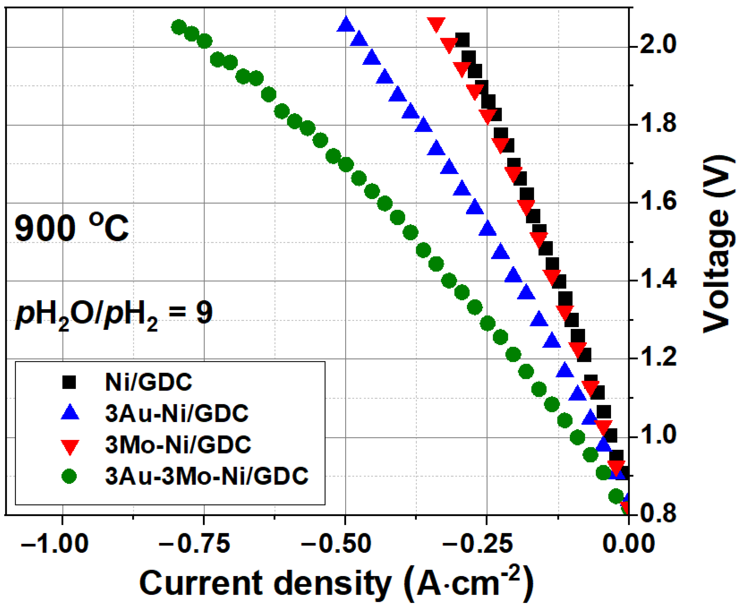
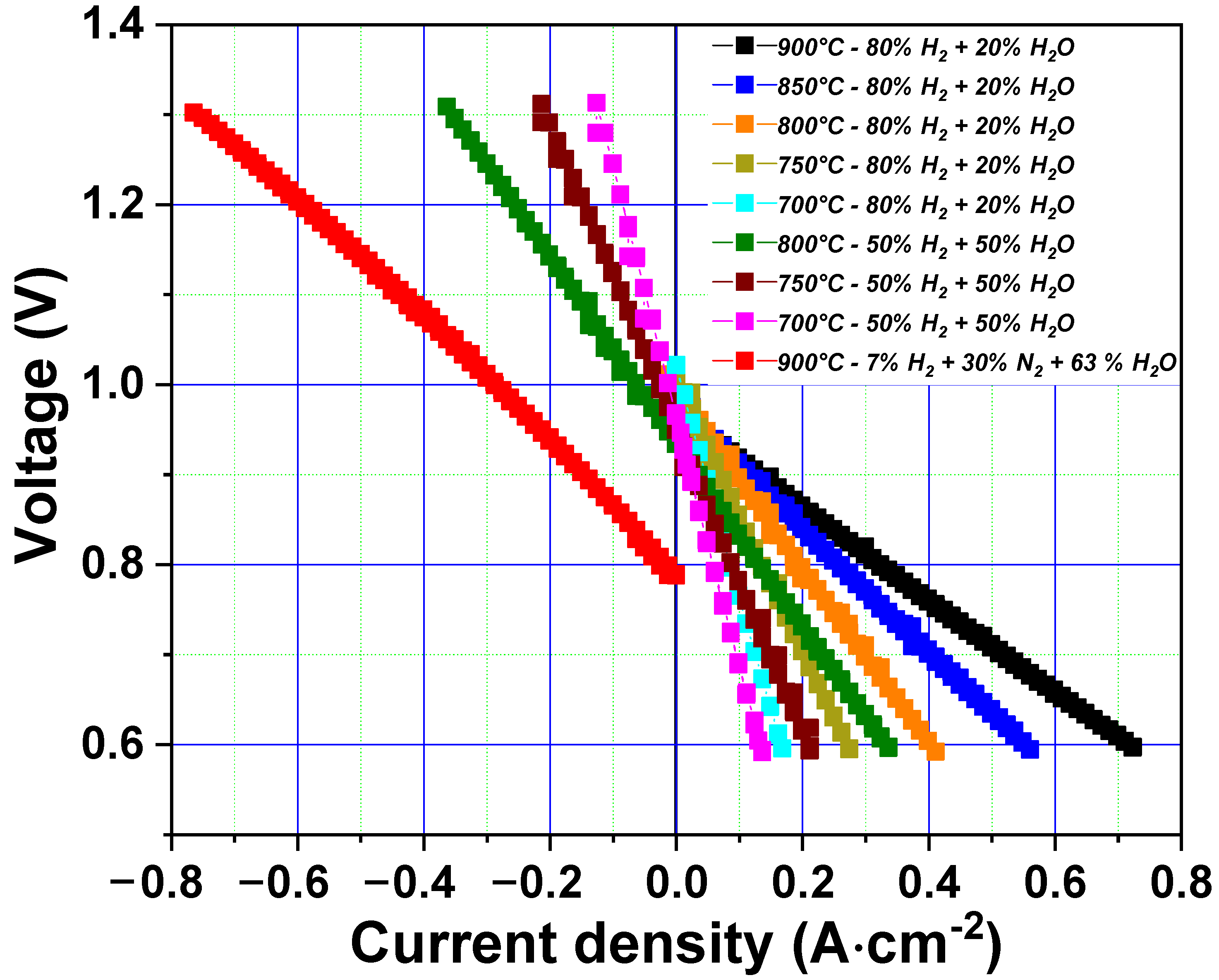
3.1. Single Cell Performance

The first electrochemical measurement was performed with the 3Mo-3Au-Ni-GDC/8YSZ/GDC/LSCF single cell without a NiO current collecting layer, under various temperatures and gas flow conditions. The open circuit voltages (OCVs) for every condition were in good agreement with the theoretical ones; for instance, an OCV value of 0.80 V was obtained with 7 vol.% H2, 30 vol.% N2, and 63 vol.% H2O at 900 °C.
The I-V curves and measurement conditions are presented in the Supplementary Information Figure S1. For example, the cell shows only −76 mA·cm−2 current density at 1.3 V at 800 °C with 50 vol.% H2O and 50 vol.% H2O gas mixture, mainly due to poor contact with the thin fuel electrode layer. Therefore, to improve the contact and current collection, a thin NiO layer (4–5 µm) was deposited on the fuel electrode, before mounting the cell in the measurement setup. This NiO current collecting layer enhances the lateral conductivity and hence improves the overall performance of the cell.
Figure 2 depicts I-V curves for the 3Mo-3Au-Ni-GDC/8YSZ/GDC/LSCF single cell with a NiO contact layer. For example, the same 3Mo-3Au-Ni-GDC/8YSZ/GDC/LSCF single cell with a NiO layer shows a high current density of −361 mA·cm−2 at 1.3 V at 800 °C with 50 vol.% H2 and 50 vol.% H2O gas mixture. An even higher current density i.e., −780 mA·cm−2 at 1.3 V is observed at 900 °C under steam electrolysis conditions with 7 vol.% H2 and, 30 vol.% N2, and 63 vol.% H2O mixture. As expected, the cell performance was improved with the NiO contact layer. The obtained current density value in this work is relatively high in comparison to the previously reported data on the button cells, under the same measurement conditions. For example, Neofytidis et al. have compared the performance of a 3Mo-3Au-Ni-GDC/8YSZ/GDC/LSCF single cell with a Ni-GDC/8YSZ/GDC/LSCF single cell and reported current densities of −250 and −100 mA·cm−2 respectively, at 1.3 V under the same measurement conditions [29]. However, in the reported work, the authors did not use the NiO current collecting layer.

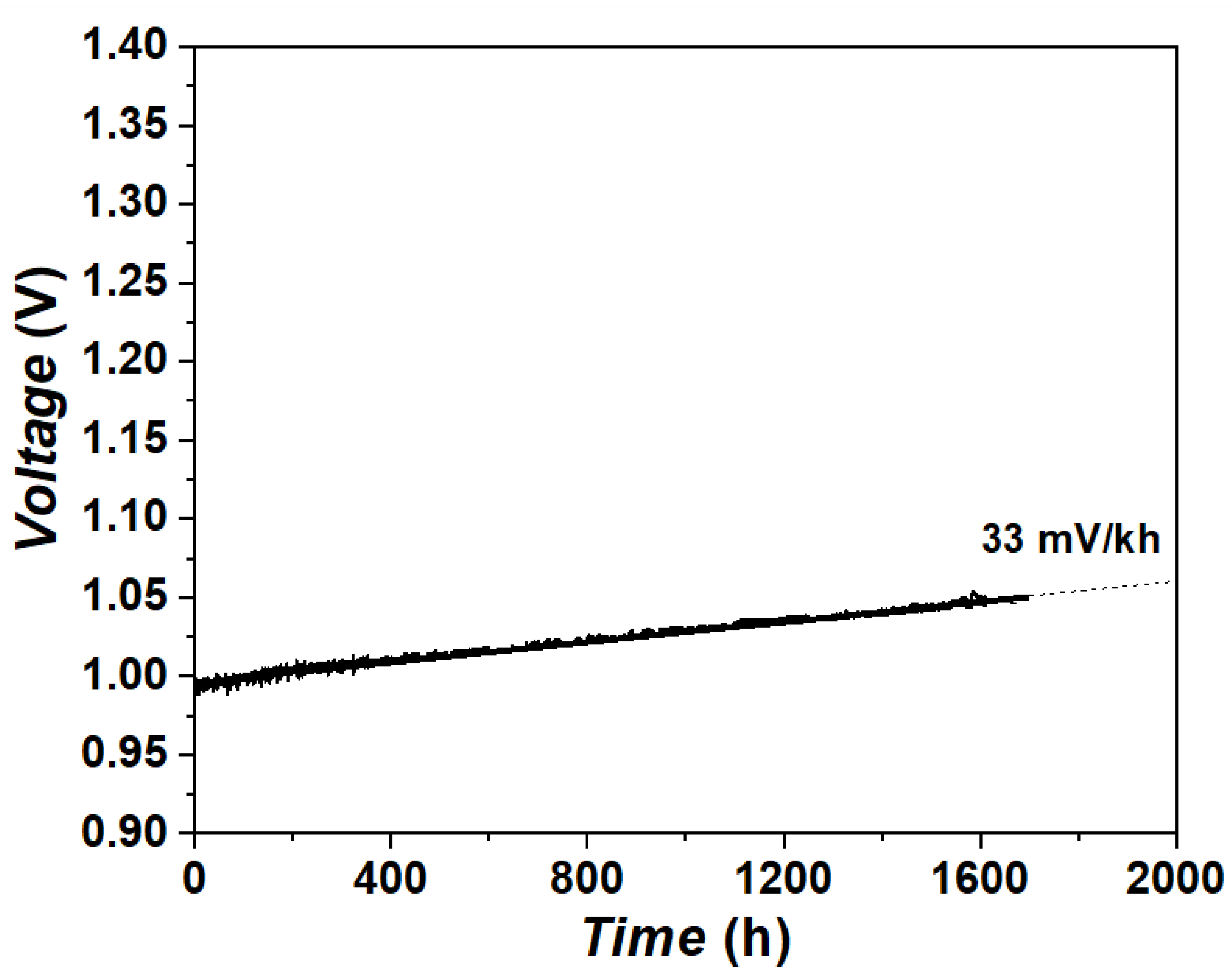
3.2. Long-Term Stability Test under Steam Electrolysis Conditions

The long-term stability test, up to 1700 h under steam electrolysis conditions, was performed with 3Mo-3Au-Ni-GDC/8YSZ/GDC/LSCF single cells at a constant current load of −0.3 A·cm−2 with 7 vol.% H2, 30 vol.% N2, and 63 vol.% H2O mixture (6 NLh−1 H2 + 21 NLh−1 N2 + 45 NLh−1 H2O flow on the fuel electrode side and 150 NLh−1 air flow on the oxygen electrode side).
The long-term stability curve (electrolysis voltage vs. time plot) of the single cell is depicted in Figure 3. During the stability test, the voltage of the cell was increased from 0.99 to 1.05 V after 1700 h of operation. Moreover, a degradation rate of 33 mV·kh−1 was calculated from the cell voltage vs. time curve. This degradation rate is quite low in comparison to the other reported data in the literature for Ni-YSZ or Ni-GDC electrodes containing a single cell. For instance, Sciazko et al. have recently compared the degradation behavior of single cells comprising Ni-YSZ and Ni-GDC fuel electrodes, and LSCF oxygen electrodes at a current density of −0.2 A·cm−2 under steam electrolysis condition at 800 °C with a H2:H2O:N2 = 45:45:10 fuel gas mixture for 100 h [31]. The authors have shown that the single cell comprising Ni-GDC electrode shows better initial cell performance; however, it shows a large degradation compared to Ni-YSZ electrodes. For instance, cell voltages were increased ~180 and ~120 mV for Ni-GDC and Ni-YSZ electrodes containing single cells, respectively, after 100 h. In our work, we obtained a significantly lower degradation rate up to 1700 h for the 3Mo-3Au-Ni-GDC electrode at 900 °C with a −0.3 A·cm−2 current load.

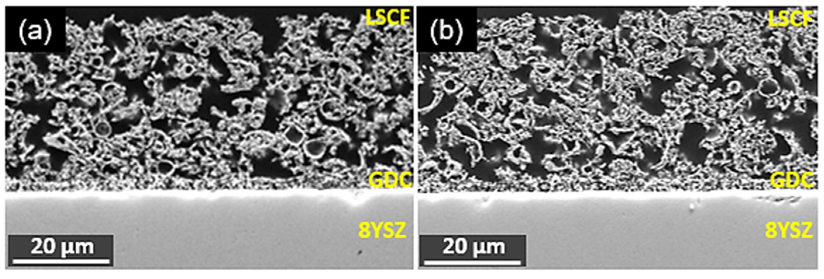
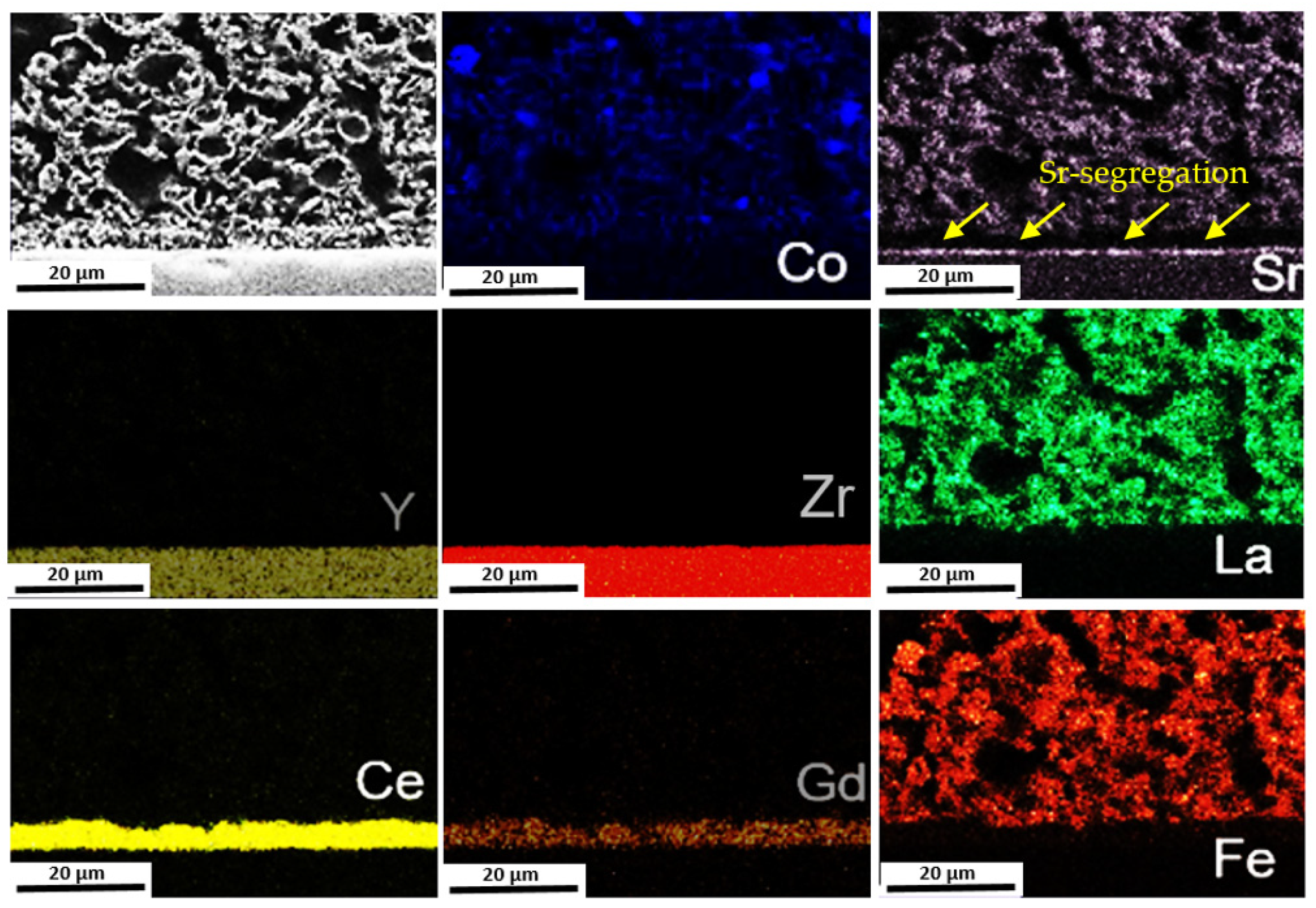
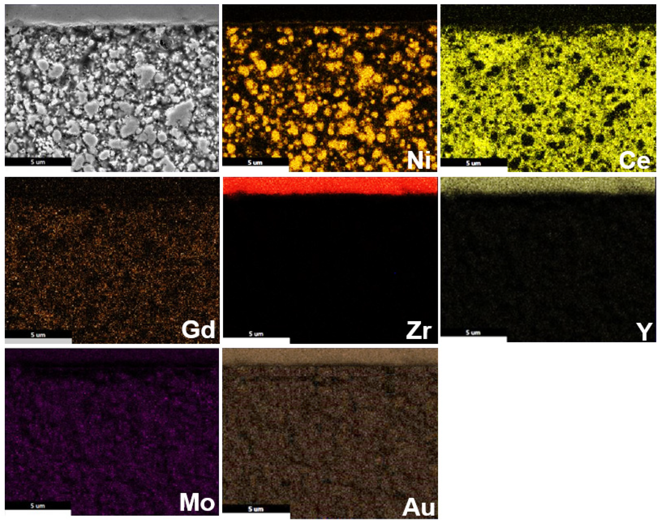
3.3. Post-Test Analysis

After carrying out the long-term stability test up to 1700 h, the single cells were embedded in an epoxy resin and mirror-polished along the cross-section prior to SEM-EDX analysis. For comparison, the SEM analysis of a freshly prepared reduced cell was also carried out. The analyses were focused on the bulk of the LSCF oxygen electrode, LSCF/GDC interface, electrolyte, GDC/electrolyte interface, electrolyte/3Mo-3Au-Ni-GDC interface, and bulk of the 3Mo-3Au-Ni-GDC electrode. It is worth mentioning that no severe damage such as delamination or cracks was observed in any of the electrodes or electrolytes after the long-term stability test.
Figure 4a,b compares the bulk of LSCF oxygen electrode, LSCF/GDC interface, GDC/8YSZ electrolyte interface, and 8YSZ electrolyte before and after 1700 h of degradation test. No significant change is observed in the 8YSZ electrolyte, or at the GDC/8YSZ or GDC/LSCF interface before and after the long-term stability test. The EDX mapping was also carried out on the cross-section of the cell before and after the degradation test. The SEM image and the corresponding EDX elemental mapping for La (Lα, 4.65 keV), Sr (Lα, 1.81 keV), Co (Kα, 6.92 keV), Fe (Kα, 6.40 keV), Ni (Kα, 7.47 keV), Ce (Lα, 4.84 keV), Zr (Lα, 2.04 keV), Gd (Lα, 6.06 keV), Y (Lα, 1.92 keV), Au (Lα, 9.71 keV), and Mo (Lα, 2.29 keV) is presented in Figure 5.
On the oxygen electrode side, two main issues, i.e., (a) formation of cobalt-oxide particles within the electrode and (b) Sr segregation at the GDC/8YSZ interface, were detected (Figure 5). The Sr-segregation is observed because the volatile SrO migrates from the LSCF electrode to GDC/electrolyte interface [32]. Furthermore, it reacts with 8YSZ to form an insulating strontium zirconate (SrZrO3) phase and hence reduces the performance of the cell. Fang et al. [33] have shown the degradation behavior of Ni-YSZ-supported stack cells with 8YSZ electrolyte, GDC barrier layer, and LSCF oxygen electrode, and reported a large increase in the ohmic resistance long-term, possibly owing to the formation of SrZrO3 phase. Similarly, Monaco et al. have recently reported the long-term degradation phenomenon of the LSCF oxygen electrode with a GDC barrier layer, under both fuel cell and electrolysis mode, using synchrotron X-ray micro-diffraction and micro-florescence techniques [34]. The authors have also observed a large degradation and increase in the ohmic resistance in the electrolysis mode during long-term and confirmed SrZrO3 phase formation between 8YSZ and GDC layer. The formation of SrZrO3 phase leads to loss of Zr4+ cations from the 8YSZ electrolyte and facilitates the inter-diffusion of Gd, which further decreases the ionic conductivity of the electrolyte, and hence a large increase in the ohmic resistance is observed [34].
In addition, the formation of cobalt oxide particles is also observed, as shown in the EDX mapping of cobalt (Figure 5). The SEM-EDX analysis of a freshly prepared cell was also performed, and the results are presented in Supplementary Information Figure S2. The cobalt particle’s formation, as well as Sr segregation, was not observed for the as-prepared cell, indicating that these processes are occurring during the long-term degradation test. Hjalmarsson et al. [35] have shown the depletion of both strontium and cobalt in the (La0.6Sr0.4)0.99CoO3-GDC composite electrodes after long-term co-electrolysis tests up to 2700 h at −1 A·cm−2 and 800 °C, for a Ni-YSZ-supported single cell with an YSZ electrolyte and GDC barrier layer. This suggests that the charge compensation because of the Sr segregation occurs by the reduction of Co4+ to Co3+ cations instead of Fe4+ cations, which further affect the oxygen vacancy concentrations and hence the electro-catalytic activity of the LSCF electrode [36].
Figure 6a,b compares the 8YSZ/3Mo-3Au-Ni-GDC electrode interface and the bulk of 3Mo-3Au-Ni-GDC fuel electrode before and after the 1700 h degradation test. For the freshly reduced cell, the particles of Ni, Au, Mo, and GDC are homogeneously distributed within the electrode as well as at the electrode/electrolyte interface (Figure 6a, secondary electron image; Figure 6c, backscattered electron image). In the SEM micrographs, the grey particles are nickel, the bright fine particles are GDC, and the porosity is black. After 1700 h of SOEC operation, Ni particle coarsening and depletion away from the electrolyte is clearly observed, as shown in Figure 6b (secondary electron image) and Figure 6d (back scattered electron image). Comparing the microstructure of the as-reduced cell and the aged cell, it can be noticed that the Ni particles tend to coalesce and form larger clusters. Moreover, an increase in pore size and pore fraction are observed near the electrolyte/electrode interface (Figure 6b,d). In addition, the coverage of Ni particles by GDC as well as loss in the GDC percolation are also observed compared to the as-reduced cell (Figure 6e,f).
Figure 7 depicts the SEM-EDX mapping of the fuel electrode/electrolyte interface and the bulk of the fuel electrode. The elemental mapping of Ni clearly shows the Ni depletion in the region of ~10 µm away from the electrolyte. In addition, some Ce and Gd agglomeration is also observed. The Au particles in the electrolyte are also observed due to the sputtering of a thin gold layer. However, the evidence of Au/Mo agglomeration or depletion is not clearly visible. The EDX mapping was also carried out on the fuel electrode side of a freshly reduced cell and the results are shown in the Supplementary Information Figure S3. The agglomeration of Ce and Gd was also present, indicating that the powder of 3Mo-3Au-Ni-GDC was not homogenous and contained some aggregates of GDC. In fact, Ni depletion and agglomeration are well known for the Ni-YSZ and Ni-GDC electrodes in SOCs [20,31]. Finally, it can be concluded that the dispersion of small amounts of Au and Mo significantly improves the catalytic activity of the fuel electrode; however, it is unable to mitigate the Ni migration.

4. Conclusions

The electrochemical performance and long-term stability of 8YSZ-electrolyte-supported 5 × 5 cm2 single cells, comprising a 3Mo-3Au-Ni-GDC fuel electrode and LSCF oxygen electrode, were investigated under steam electrolysis conditions. A maximum current density of −0.78 A·cm−2 was obtained at 1.3 V with 7 vol.% H2, 30 vol.% N2, and 63 vol.% H2O fuel gas mixture at 900 °C. The long-term degradation test was carried out at −0.3 A·cm−2 current load for 1700 h under the same measurement conditions and a degradation rate of 33 mV·kh−1 was observed.
The post-test analyses using SEM-EDX were carried out in order to understand the cell degradation mechanism during long-term operation. In the fuel electrode, Ni depletion and agglomeration away from the electrolyte were observed. Additionally, the coverage of Ni particles by GDC as well as loss in the GDC percolation was also detected. Thus, even though modification with small amounts of 0.3 wt% Mo and 2.3 wt% Au seems to significantly improve the electro-catalytic activity of the fuel electrode and to decrease the degradation rate under SOE performance, it does not significantly mitigate the Ni migration phenomena after prolonged operation. In this respect, current efforts focus on clarifying the optimum concentration for Mo, Au, and of other dopants (e.g., Fe [37]), in order to further enhance and stabilize the promoting effect by the modifications, as well as to understand how to better mitigate Ni migration. Additionally, pore formation near the electrolyte/electrode interface is also observed. In the oxygen electrode, Sr segregation at the GDC/electrolyte interface as well as the formation of cobalt oxide particles is observed. Overall, degradation in both oxygen and fuel electrodes is responsible for the degradation of the cell.

Supplementary Materials

The following supporting information can be downloaded at: https://www.mdpi.com/article/10.3390/en15082726/s1, Figure S1: I-V curves for the 3Mo-3Au-Ni-GDC/8YSZ/GDC/LSCF single cell under different temperature and fuel gas composition, without NiO current collecting layer; Figure S2: Elemental mapping on the oxygen electrode side, at the cross-section of as reduced 3Mo-3Au-Ni-GDC/8YSZ/GDC/LSCF single cell; Figure S3: Elemental mapping on the fuel electrode side, at the cross-section of as reduced 3Mo-3Au-Ni-GDC/8YSZ/GDC/LSCF single cell.

Author Contributions

Conceptualization, V.V., I.C.V., D.K.N. and L.G.J.d.H.; methodology, V.V., I.C.V., D.K.N.; software, V.V. and I.C.V.; validation, V.V., I.C.V. and D.K.N.; formal analysis, V.V. and I.C.V.; investigation, V.V. and F.Z.; resources, I.C.V., D.K.N., S.G.N., R.-A.E. and L.G.J.d.H.; writing—original draft preparation, V.V.; writing—review and editing, V.V., I.C.V., D.K.N. and L.G.J.d.H.; visualization, V.V., I.C.V., D.K.N., S.G.N. and L.G.J.d.H.; supervision, I.C.V., D.K.N., S.G.N., R.-A.E. and L.G.J.d.H.; project administration, I.C.V., D.K.N., S.G.N., R.-A.E. and L.G.J.d.H.; funding acquisition, I.C.V., D.K.N., S.G.N., R.-A.E. and L.G.J.d.H. All authors have read and agreed to the published version of the manuscript.

Funding

The research leading to these results has received funding from the Fuel Cells and Hydrogen 2 Joint Undertaking under the project SElySOs with Grant Agreement No: 671481. This Joint Undertaking receives support from the European Union’s Horizon 2020 Research and Innovation Programme and Greece, Germany, Czech Republic, France, and Norway.

Institutional Review Board Statement

Not applicable.

Informed Consent Statement

Not applicable.

Data Availability Statement

Not applicable.

Acknowledgments

The authors acknowledge Claudia Tropartz and Tanja Brambach for their valuable help with the electrochemical measurements.

Conflicts of Interest

The authors declare no conflict of interest.

References

  1. Herring, J.S.; O’Brien, J.E.; Stoots, C.M.; Hawkes, G.L.; Hartvigsen, J.J.; Shahnam, M. Progress in high-temperature electrolysis for hydrogen production using planar SOFC technology. Int. J. Hydrogen Energy 2007, 32, 440–450. [Google Scholar] [CrossRef] [Green Version]
  2. Nikolaidis, P.; Poullikkas, A. A comparative overview of hydrogen production processes. Renew. Sustain. Energy Rev. 2017, 67, 597–611. [Google Scholar] [CrossRef]
  3. Kumar, S.S.; Himabindu, V. Hydrogen production by PEM water electrolysis—A review. Mater. Sci. Energy Technol. 2019, 2, 442–454. [Google Scholar]
  4. Doenitz, W.; Schmidberger, R.; Steinheil, E.; Streicher, R. Hydrogen production by high temperature electrolysis of water vapour. Int. J. Hydrogen Energy 1980, 5, 55–63. [Google Scholar] [CrossRef]
  5. Posdziech, O.; Schwarze, K.; Brabandt, J. Efficient hydrogen production for industry and electricity storage via high-temperature electrolysis. Int. J. Hydrogen Energy 2019, 44, 19089–19101. [Google Scholar] [CrossRef]
  6. Foit, S.R.; Vinke, I.C.; De Haart, L.G.J.; Eichel, R.-A. Power-to-Syngas: An Enabling Technology for the Transition of the Energy System? Angew. Chem. Int. Ed. 2017, 56, 5402–5411. [Google Scholar] [CrossRef]
  7. Jensen, S.H.; Larsen, P.H.; Mogensen, M.B. Hydrogen and synthetic fuel production from renewable energy sources. Int. J. Hydrogen Energy 2007, 32, 3253–3257. [Google Scholar] [CrossRef]
  8. Foit, S.; Dittrich, L.; Duyster, T.; Vinke, I.; Eichel, R.-A.; De Haart, L. Direct Solid Oxide Electrolysis of Carbon Dioxide: Analysis of Performance and Processes. Processes 2020, 8, 1390. [Google Scholar] [CrossRef]
  9. Ma, Z.; Zhou, J.; Li, Y.; Liu, C.; Pu, J.; Chen, X. Developments in CO2 Electrolysis of Solid Oxide Electrolysis Cell with Different Cathodes▴. Fuel Cells 2020, 20, 650–660. [Google Scholar] [CrossRef]
  10. Ebbesen, S.D.; Sun, X.; Mogensen, M.B. Understanding the processes governing performance and durability of solid oxide electrolysis cells. Faraday Discuss. 2015, 182, 393–422. [Google Scholar] [CrossRef]
  11. Chen, K.; Jiang, S.P. Review—Materials Degradation of Solid Oxide Electrolysis Cells. J. Electrochem. Soc. 2016, 163, F3070–F3083. [Google Scholar] [CrossRef]
  12. Graves, C.; Ebbesen, S.D.; Jensen, S.H.; Simonsen, S.B.; Mogensen, M.B. Eliminating degradation in solid oxide electrochemical cells by reversible operation. Nat. Mater. 2015, 14, 239–244. [Google Scholar] [CrossRef] [PubMed]
  13. Zhang, X.; Song, Y.; Wang, G.; Bao, X. Co-electrolysis of CO2 and H2O in high-temperature solid oxide electrolysis cells: Recent advance in cathodes. J. Energy Chem. 2017, 26, 839–853. [Google Scholar] [CrossRef] [Green Version]
  14. Liang, M.; Yu, B.; Wen, M.; Chen, J.; Xu, J.; Zhai, Y. Preparation of NiO–YSZ composite powder by a combustion method and its application for cathode of SOEC. Int. J. Hydrogen Energy 2010, 35, 2852–2857. [Google Scholar] [CrossRef]
  15. Ebbesen, S.D.; Graves, C.R.; Mogensen, M.B. Production of Synthetic Fuels by Co-Electrolysis of Steam and Carbon Dioxide. Int. J. Green Energy 2009, 6, 646–660. [Google Scholar] [CrossRef]
  16. Ebbesen, S.D.; Jensen, S.H.; Hauch, A.; Mogensen, M.B. High Temperature Electrolysis in Alkaline Cells, Solid Proton Conducting Cells, and Solid Oxide Cells. Chem. Rev. 2014, 114, 10697–10734. [Google Scholar] [CrossRef]
  17. Mougin, J.; Mansuy, A.; Chatroux, A.; Gousseau, G.; Petitjean, M.; Reytier, M.; Mauvy, F. Enhanced Performance and Durability of a High Temperature Steam Electrolysis Stack. Fuel Cells 2013, 13, 623–630. [Google Scholar] [CrossRef]
  18. Fu, Q.; Schefold, J.; Brisse, A.; Nielsen, J.U. Durability Testing of a High-Temperature Steam Electrolyzer Stack at 700 °C. Fuel Cells 2014, 14, 395–402. [Google Scholar] [CrossRef]
  19. Trini, M.; Hauch, A.; De Angelis, S.; Tong, X.; Hendriksen, P.V.; Chen, M. Comparison of microstructural evolution of fuel electrodes in solid oxide fuel cells and electrolysis cells. J. Power Sources 2020, 450, 227599. [Google Scholar] [CrossRef]
  20. Mogensen, M.B.; Chen, M.; Frandsen, H.L.; Graves, C.; Hauch, A.; Hendriksen, P.V.; Jacobsen, T.; Jensen, S.H.; Skafte, T.L.; Sun, X. Ni migration in solid oxide cell electrodes: Review and revised hypothesis. Fuel Cells 2021, 21, 415–429. [Google Scholar] [CrossRef]
  21. Schefold, J.; Brisse, A.; Poepke, H. 23,000 h steam electrolysis with an electrolyte supported solid oxide cell. Int. J. Hydrogen Energy 2017, 42, 13415–13426. [Google Scholar] [CrossRef]
  22. Singh, V.; Muroyama, H.; Matsui, T.; Hashigami, S.; Inagaki, T.; Eguchi, K. Feasibility of alternative electrode materials for high temperature CO2 reduction on solid oxide electrolysis cell. J. Power Sources 2015, 293, 642–648. [Google Scholar] [CrossRef]
  23. Schefold, J.; Brisse, A.; Poepke, H. Long-term Steam Electrolysis with Electrolyte-Supported Solid Oxide Cells. Electrochim. Acta 2015, 179, 161–168. [Google Scholar] [CrossRef]
  24. Kim-Lohsoontorn, P.; Bae, J. Electrochemical performance of solid oxide electrolysis cell electrodes under high-temperature coelectrolysis of steam and carbon dioxide. J. Power Sources 2011, 196, 7161–7168. [Google Scholar] [CrossRef]
  25. Niakolas, D.K.; Neofytidis, C.S.; Neophytides, S.G. Effect of Au and/or Mo Doping on the Development of Carbon and Sulfur Tolerant Anodes for SOFCs—A Short Review. Front. Environ. Sci. 2017, 5, 78. [Google Scholar] [CrossRef] [Green Version]
  26. Riegraf, M.; Hoerlein, M.P.; Costa, R.; Schiller, G.; Friedrich, K.A. Sulfur Poisoning of Electrochemical Reformate Conversion on Nickel/Gadolinium-Doped Ceria Electrodes. ACS Catal. 2017, 7, 7760–7771. [Google Scholar] [CrossRef]
  27. Zhang, L.; Jiang, S.P.; He, H.Q.; Chen, X.; Ma, J.; Song, X.C. A comparative study of H2S poisoning on electrode behavior of Ni/YSZ and Ni/GDC anodes of solid oxide fuel cells. Int. J. Hydrogen Energy 2010, 35, 12359–12368. [Google Scholar] [CrossRef]
  28. Ioannidou, E.; Neofytidis, C.; Sygellou, L.; Niakolas, D. Au-doped Ni/GDC as an Improved Cathode Electrocatalyst for H2O Electrolysis in SOECs. Appl. Catal. B Environ. 2018, 236, 253–264. [Google Scholar] [CrossRef]
  29. Neofytidis, C.; Ioannidou, E.; Sygellou, L.; Kollia, M.; Niakolas, D. Affecting the H2O electrolysis process in SOECs through modification of NiO/GDC; experimental case of Au-Mo-Ni synergy. J. Catal. 2019, 373, 260–275. [Google Scholar] [CrossRef]
  30. Courty, P.; Ajot, H.; Marcilly, C.; Delmon, B. Oxydes mixtes ou en solution solide sous forme très divisée obtenus par décomposition thermique de précurseurs amorphes. Powder Technol. 1973, 7, 21–38. [Google Scholar] [CrossRef]
  31. Sciazko, A.; Shimura, T.; Komatsu, Y.; Shikazono, N. Ni-GDC and Ni-YSZ electrodes operated in solid oxide electrolysis and fuel cell modes. J. Therm. Sci. Technol. 2021, 16, JTST0013. [Google Scholar] [CrossRef]
  32. Vibhu, V.; Yildiz, S.; Vinke, I.C.; Eichel, R.-A.; Bassat, J.-M.; De Haart, L.G.J. High Performance LSC Infiltrated LSCF Oxygen Electrode for High Temperature Steam Electrolysis Application. J. Electrochem. Soc. 2019, 166, F102–F108. [Google Scholar] [CrossRef]
  33. Fang, Q.; Blum, L.; Menzler, N.H. Performance and Degradation of Solid Oxide Electrolysis Cells in Stack. J. Electrochem. Soc. 2015, 162, F907–F912. [Google Scholar] [CrossRef]
  34. Monaco, F.; Ferreira-Sanchez, D.; Hubert, M.; Morel, B.; Montinaro, D.; Grolimund, D.; Laurencin, J. Oxygen electrode degradation in solid oxide cells operating in electrolysis and fuel cell modes: LSCF destabilization and interdiffusion at the electrode/electrolyte interface. Int. J. Hydrogen Energy 2021, 46, 31533–31549. [Google Scholar] [CrossRef]
  35. Hjalmarsson, P.; Søgaard, M.; Mogensen, M.B. Electrochemical performance and degradation of (La0.6Sr0.4)0.99CoO3−δ as porous SOFC-cathode. Solid State Ionics 2008, 179, 1422–1426. [Google Scholar] [CrossRef]
  36. Lay-Grindler, E.; Laurencin, J.; Villanova, J.; Kieffer, I.; Usseglio-Viretta, F.; Le Bihan, T.; Bleuet, P.; Mansuy, A.; Delette, G. Degradation Study of the La0.6Sr0.4Co0.2Fe0.8O3 Solid Oxide Electrolysis Cell (SOEC) Anode after High Temperature Electrolysis Operation. ECS Trans. 2013, 57, 3177–3187. [Google Scholar] [CrossRef]
  37. Neofytidis, C.; Ioannidou, E.; Kollia, M.; Neophytides, S.G.; Niakolas, D.K. The promoting effect of Fe on Ni/ GDC for the Solid Oxide H 2 O electrolysis. Int. J. Energy Res. 2020, 44, 10982–10995. [Google Scholar] [CrossRef]
Figure 1. The I-V curves at 900 °C for an electrolyte-supported single cell comprising (■) Ni/GDC, () 3Au-Ni/GDC, () 3Mo-Ni/GDC, and () 3Au-3Mo-Ni/GDC as the fuel electrode and LSCF as the oxygen electrode. Adapted with permission from [29].
Energies 15 02726 g001
Figure 2. I-V curves for the 3Mo-3Au-Ni-GDC/8YSZ/GDC/LSCF single cell at different temperatures and fuel gas compositions.
Energies 15 02726 g002
Figure 3. Long-term stability test, i.e., cell voltage vs. time curve for the 3Mo-3Au-Ni-GDC/8YSZ/GDC/LSCF single cell up to 1700h at 900 °C with 7 vol.% H2, 30 vol.% N2, and 63 vol.% H2O feed gas mixture under −0.3 A·cm−2 current load.
Energies 15 02726 g003
Figure 4. SEM images of oxygen electrode sides, for 3Mo-3Au-Ni-GDC/8YSZ/GDC/LSCF single cells (a) before and (b) after 1700 h steam electrolysis operation at 900 °C with 63 vol.% H2O + 30 % vol.% N2 + 7 vol.% H2 feed gas mixture and −0.3 A·cm−2 current load.
Energies 15 02726 g004
Figure 5. Elemental mapping on the oxygen electrode side, at the cross-section of the 3Mo-3Au-Ni-GDC/8YSZ/GDC/LSCF single cell after 1700 h steam electrolysis operation at 900 °C with 63 vol.% H2O + 30 vol.% N2 + 7 vol.% H2 feed gas mixture and −0.3 A·cm−2 current load.
Energies 15 02726 g005
Figure 6. SEM images of fuel electrode sides for 3Mo-3Au-Ni-GDC/8YSZ/GDC/LSCF single cells (a,c,e) before and (b,d,f) after 1700 h steam electrolysis operation at 900 °C with 63 vol.% H2O + 30 vol.% N2 + 7 vol.% H2 feed gas mixture and −0.3 A·cm−2 current load. (a,b) were taken using a secondary electron detector, while (cf) were taken using a backscattered electron detector. In (cf), the bigger grey grains are Ni, and bright fine particles are GDC. (f) The coverage of Ni particles by GDC.
Energies 15 02726 g006
Figure 7. Elemental mapping on the fuel electrode side, at the cross-section of the 3Mo-3Au-Ni-GDC/8YSZ/GDC/LSCF single cell after 1700 h steam electrolysis operation at 900 °C with 63 vol.% H2O + 30 vol.% N2 + 7 vol.% H2 feed gas mixture and −0.3 A·cm−2 current load.
Energies 15 02726 g007
Publisher’s Note: MDPI stays neutral with regard to jurisdictional claims in published maps and institutional affiliations.

