Article

Performance Evaluation of an Axial Flux Machine with a Hybrid Excitation Design

Faculty of Electrical Engineering, West Pomeranian University of Technology, 70-313 Szczecin, Poland
*
Author to whom correspondence should be addressed.
Energies 2022, 15(8), 2733; https://doi.org/10.3390/en15082733
Submission received: 25 February 2022 / Revised: 29 March 2022 / Accepted: 4 April 2022 / Published: 8 April 2022
(This article belongs to the Special Issue Advanced Permanent Magnet Machines and Drives)

Abstract

:
Variable speed, permanent magnet synchronous machines with hybrid excitation have attracted much attention due to their flux-control potential. In this paper, a design of permanent magnet axial flux machines with iron poles in the rotor and an additional electrically controlled source of excitation fixed on the stator is presented. This paper shows results pertaining to air-gap flux control, electromagnetic losses, electromagnetic torque, back emf and efficiency maps obtained through field-strengthening and weakening operations and investigated by 3D finite element analysis. Moreover, the temperature distribution of the machine was analyzed according to the fluid–thermal coupling method. The presented machine was prototyped and experimentally tested to validate the effectiveness of numerical models and achieved results.

1. Introduction

Nowadays, electrical machines with high efficiency and good reliability are required. Although permanent magnet machines are suitable and have excellent efficiency, they have some flux-control limitations, especially in the field-weakening region at high rotor speed [1]. Permanent magnet (PM) machines with flux-weakening features are desirable in drives with a wide range of rotational speeds (e.g., in electrical vehicles or in wind turbine generators operated under different weather conditions).
Alternative design solutions for permanent magnet machines with hybrid excitation (HE) have been proposed, in which there is an additional source of field excitation, usually in the form of an additional coil electrically controlled by DC current and fixed on the machine stator [2,3]. The air-gap magnetic flux density is created by PMs and an additional magnetic field excited by the DC coil. In contrast to a parallel HE system, a serial one has an additional magnetic flux that directly affects the PM and changes the operating point of the magnet. Hence, the parallel system is more suitable for magnets from a demagnetization point of view.
Significant progress in hybrid excitation machines can also be observed in reluctance or synRM machines [4,5,6,7] and permanent magnet synchronous machines [8,9,10,11,12]. An additional excitation coil can be fixed on the stator [13,14] or in the rotor [15,16], which depends on the concept. In the literature, axial flux machines with hybrid excitation concepts [15,16,17,18,19,20,21,22,23] can be found where an additional coil is most often fixed on the stator.
In this paper, a concept of axial flux machines with permanent magnets, iron poles and an additional DC coil for magnetic flux control fixed in the middle on the stator is presented. The advantages of the proposed machine design solution are: a good range of magnetic flux regulation, brushless supplying stator windings and an additional coil, no demagnetization risk for the magnets, low cost and volume of the magnets compared to conventional machines and a high efficiency of up to 95%. The main drawbacks are: extra space needed to place the additional coil, additional losses from the supply DC coil and increased cooling requirements.

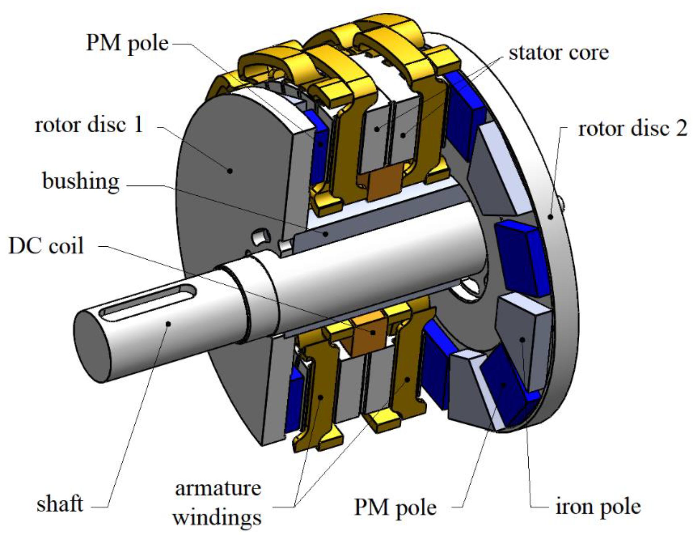
2. Dual-Disc Axial Flux Machine Design with Hybrid Excitation Concept

Figure 1 presents a design of a 3-phase, 12-pole dual-disc axial flux machine with a hybrid excitation parallel system using an additional DC coil. The presented machine concept has been partially analyzed in [24,25]. An additional DC coil with the number of turns NDC = 500 allows control of the air-gap magnetic flux density. The stator is built from the toroidal core with armature windings. Every core’s side has 36 half-opened slots, in which three-phase windings are placed. The DC coil creates a magnetomotive force (MMF) of 2500   AT by a DC coil current of 5 A. The rotor is built from two steel discs with permanent magnets of type N38H with a remanence of 1.23 T and coercivity of 947.8 kA/m. The iron poles are made from solid steel. The rotor discs are connected together with ferromagnetic bushing. The stator’s core is built from two similar, one-side-slotted toroids based on grain-oriented electrical steel wound cores.
Figure 2a shows that the main parts of the rotor were made of two steel discs connected with ferromagnetic bushing, which form the yoke of the machine. On each rotor’s disc, six neodymium magnets with uniform polarization are placed with iron poles (IP), which do not have polarity on their own. The solid magnet’s shape is square and the IP’s shape is trapezoidal; the IP’s size is given in Figure 2b.

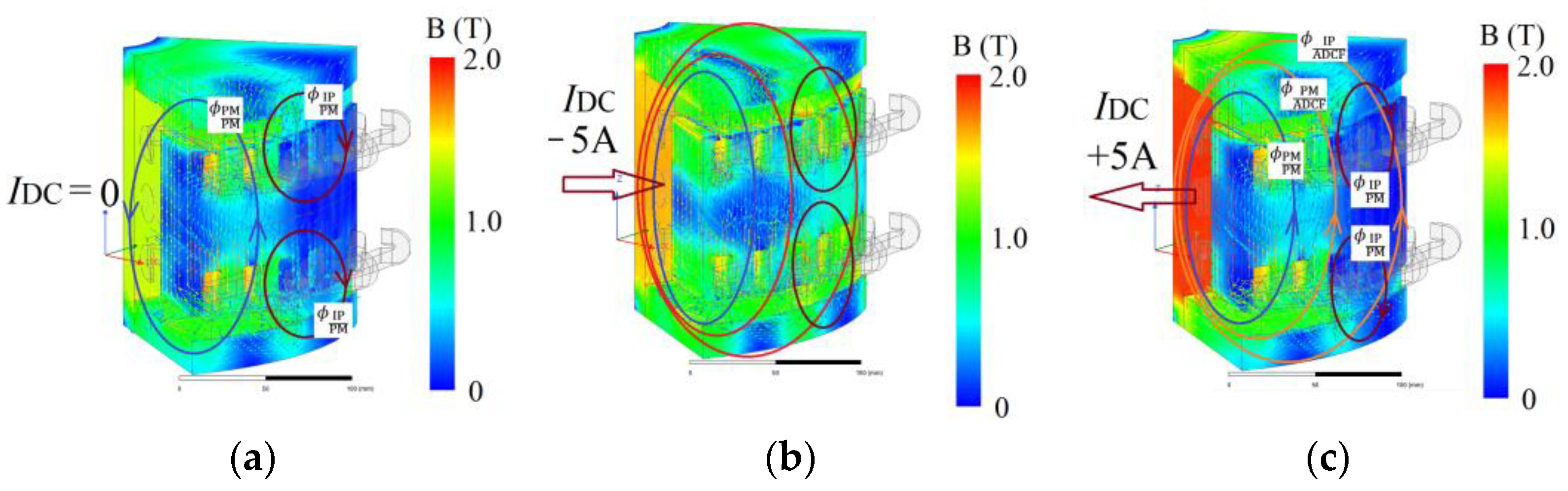
3. Principle of Flux Control

Since the rotor poles of the machine are different shapes, as can be seen in Figure 2, and they have dissimilar magnetic properties, the air-gap flux ϕ g of the machine will be strongly dependent on the difference between the air-gap flux of the PM pole ϕ g PM and the air-gap flux of the iron pole ϕ g IP . Moreover, the influence of an additional field DC coil excited by DC current IDC on the air-gap flux density distribution is different for the PM pole and the iron pole. The magnetic pole fluxes, ϕ g PM and ϕ g IP , can be calculated:
ϕ g PM = α PM τ B m g PM π p R 2 2 R 1 2
ϕ g IP = α IP τ B m g IP π p R 2 2 R 1 2
where α PM ,   α IP are the PM pole and iron pole arc length, R 1 ,   R 2 are the rotor inner and outer radius, τ is the pitch of the pole, p is the pole-pair number and B m g PM ,   B m g IP are the maximum magnetic flux density in the air gap of the PM pole and the iron pole, respectively.
Neglecting flux leakage, a no-load magnetic flux component generated by PMs ( ϕ g PM / PM ) crosses an air gap over the PM pole in the axial direction and flows through the stator core (Figure 3a). A significant part of the flux ϕ g PM / PM crosses the second air gap of the PM, but some part of the flux is returned through an air gap over the iron pole in the form of a flux ϕ g IP / PM . The effect of the no-load air-gap magnetic flux density of the iron pole excited by the PM can clearly be observed in Figure 4a in the iron pole section (pitch of the iron pole).
When an additional magnetomotive force (mmf) is excited by the current IDC, an additional DC flux (ADCF) of the control coil ϕ ADCF is increased (Figure 3b,c). Depending on the direction of the DC coil current, air gap fluxes will strengthen or weaken. In the case of coil current IDC < 0, there will be air-gap flux strengthening for the iron pole ϕ g IP and air-gap flux weakening for the pole with a magnet ϕ g PM . In the case of IDC > 0, there will be gap flux extenuation for the iron pole ϕ g IP and gap flux amplification for the pole with a magnet ϕ g PM . The flux ϕ ADCF is conducted by a ferromagnetic bushing, the rotor’s yokes and the stator core of the machine; it passes through the air gap where it is divided into two components: flux ϕ g PM / ADCF crosses the air gap of the magnet pole and flux ϕ g IP / ADCF crosses the air gap of the iron pole. The flux ϕ ADCF can be expressed as:
ϕ ADCF = ϕ g PM / ADCF + ϕ g IP / ADCF
Neglecting saturation, flux leakage and armature effects, the magnetic air-gap flux of the PM pole ϕ g PM in the linear model can be calculated as:
ϕ g PM = ϕ g PM / PM + ϕ g PM / ADCF
The magnetic air-gap flux of the iron pole ϕ g IP can be expressed as:
ϕ g IP = ϕ g IP / ADCF ϕ g IP / PM
The magnetic flux passing through the DC coil ϕ DCF can be expressed as:
ϕ DCF = p ϕ PM / PM ϕ IP / PM + ϕ ADCF
Based on the 3D FEA results presented in Figure 4b, it can be seen that the ADCF excited by IDC = −5 A changes the amplitude of the magnetic flux density more effectively than that excited by IDC = +5 A, and the influence of the ADCF on the magnetic air-gap flux distribution is greater in the air gap of the iron pole than in the air gap of the PM pole. In order to show the effect more clearly, Figure 5 shows the air-gap magnetic flux density distribution achieved at different DC load conditions: at IDC = +5 A (Figure 5a) and at IDC = −5 A (Figure 5b) as a special case of study where PMs of the machine were replaced with air boxes.
Moreover, in order to evaluate the demagnetization risk of magnets, the air-gap magnetic flux density distribution is performed at the most unfavorable load conditions (at Isd = 70.7A and Isq = 0, where Isd is the d-axis stator current and Isq is the q-axis stator current). From the results shown in Figure 4c, it can be concluded that at operation conditions, there is no demagnetization risk of magnets in high current overload.

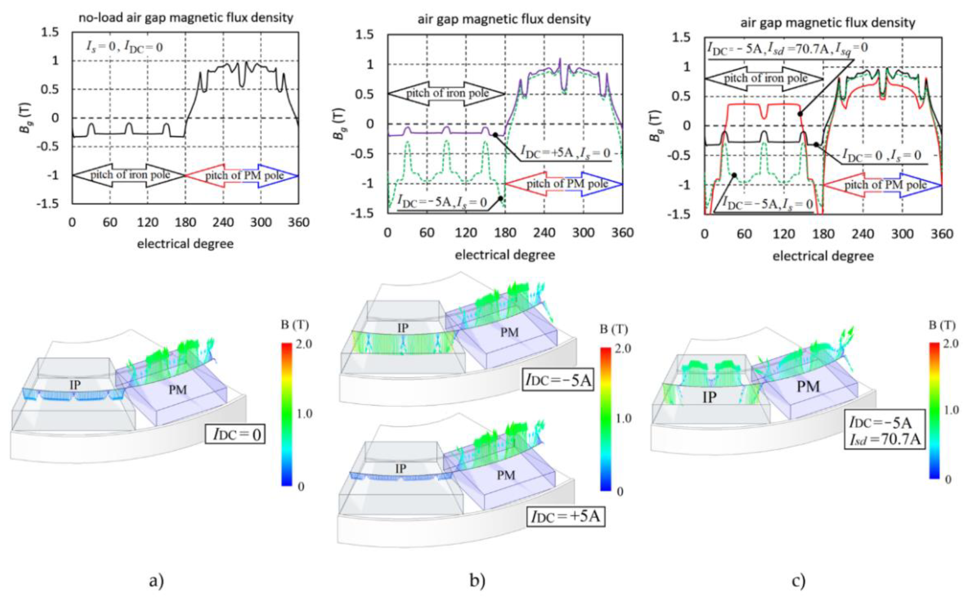
4. Magnetic Flux Density Distribution and Back EMF Analysis

In order to perform an analysis of the magnetic field distribution of the machine under different additional DC coil current excitations, a 3D model of the FCAFPMM in Ansys Electronics Desktop was developed considering symmetry conditions with respect to 1/6 part of the machine. For three cases of DC coil current excitations, magnetic field distribution results are shown in Figure 6a. Additionally, for these cases, the air-gap magnetic flux density distributions (in the middle of the gap for one pole-pair) are also shown in Figure 6b.
In the presented figures, it is clearly possible to see the strengthening effect of a current load of IDC < 0 and significant magnetic flux of the iron pole section. Moreover, in this case, there is a slight but not significant decrease in flux in the air gap for the PM pole section. In the second case, where the DC coil current changed direction (IDC > 0), there is a slight decrease in flux in the iron pole section due to the saturation effect. The effect can also clearly be seen on the rotor bushing, even in the no-load case (IDC = 0), where the maximum magnetic flux density is approximately 1.5 T. This means that the dimensions of the rotor bushing should also be optimized. The presented results also show that the additional DC field excited by the DC coil current is mostly passing through the iron pole section, and it does not significantly change the value of the air-gap flux of the PM pole, which is a desirable effect.
Finally, in order to investigate the effect of the additional DC field on the magnetic flux linked with the stator windings, initial experiments were conducted. Figure 7 shows characteristics of the no-load-induced phase voltage in the stator windings, which were obtained for three cases of the additional DC coil current excitation.
In the presented Figure 7, one can clearly observe the effect of increasing phase terminal voltages with a DC coil current of IDC = −5 A, which causes an increased rms voltage of approximately 50% from 172 V to 253 V. When the current is flowing in the opposite direction, it means at IDC = +5 A, the induced voltage is decreased by approximately 10%. It should be noted that the experimental results were similar to 3D FEA predictions.

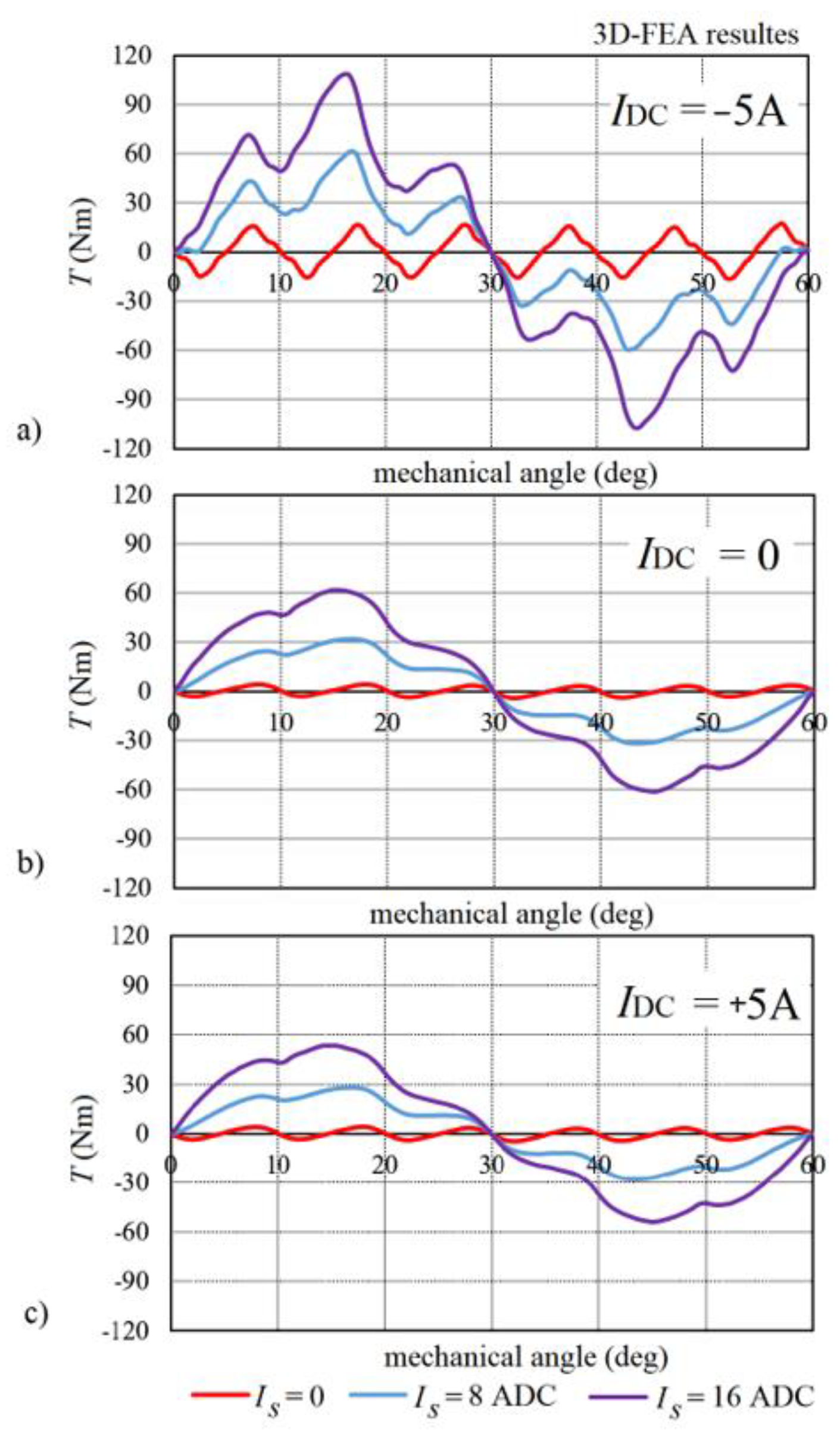
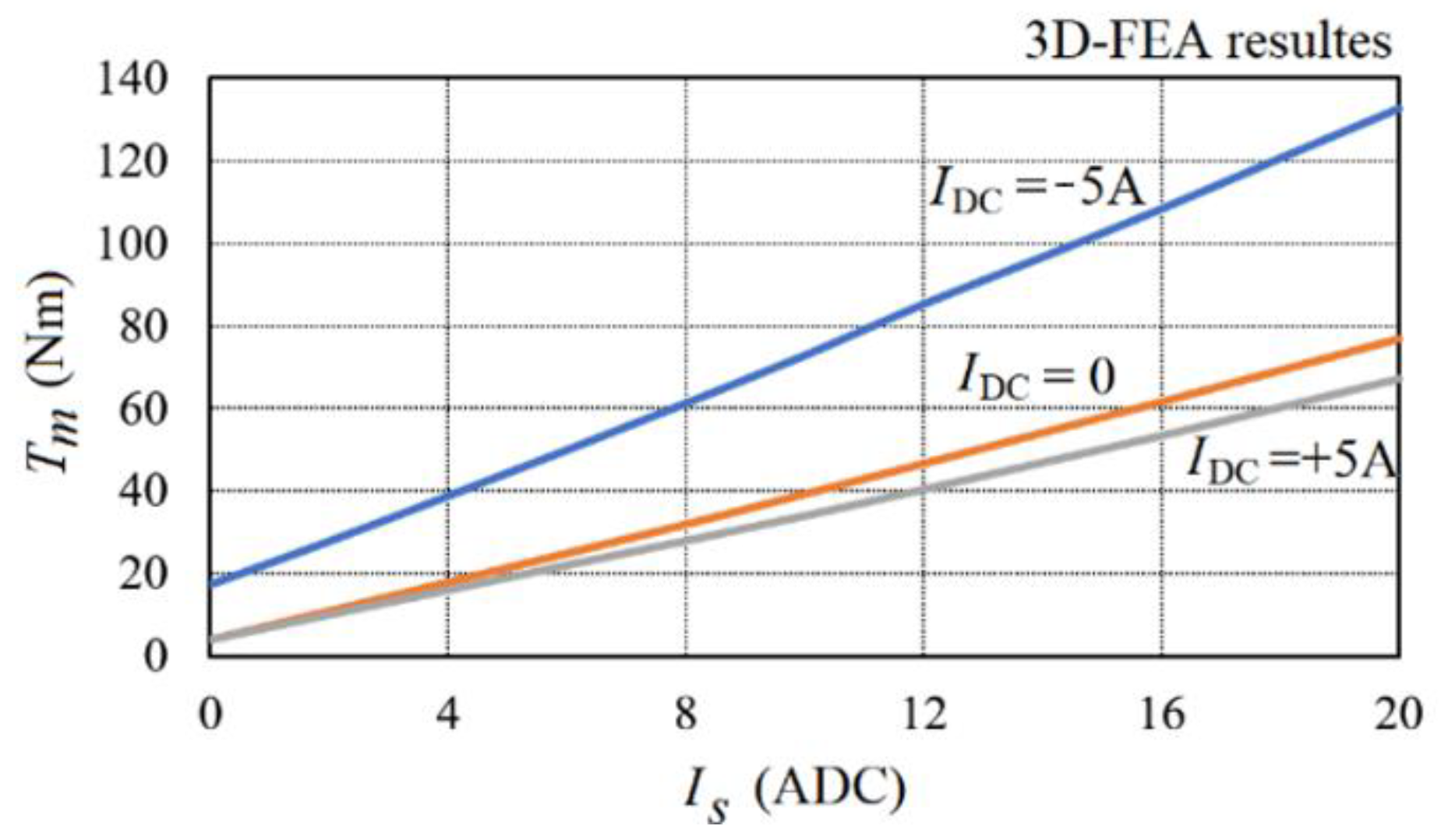
5. Electromagnetic Torque

The flux created by the DC coil affects the electromagnetic torque and torque-ripple characteristics of the machine. The influence of an additional DC field on the static torque characteristics is presented in Figure 8. The results show that, although maximum electromagnetic torque is increased two-fold with a load current of IDC = −5 A (Figure 8a), the pulsation of the torque, which is directly related to air-gap flux density, is also increased. In other cases, the torque pulsations are comparable and relatively small (Figure 8b,c). It is worth observing that the no-load cogging torque with field-strengthening is rapidly increased. Publication [21] discussed a method of cogging torque reduction by optimizing the geometry of the rotor pole pieces.
Figure 9 shows the characteristics of maximum electromagnetic static torque obtained at three different currents of the DC coil versus stator current Is.

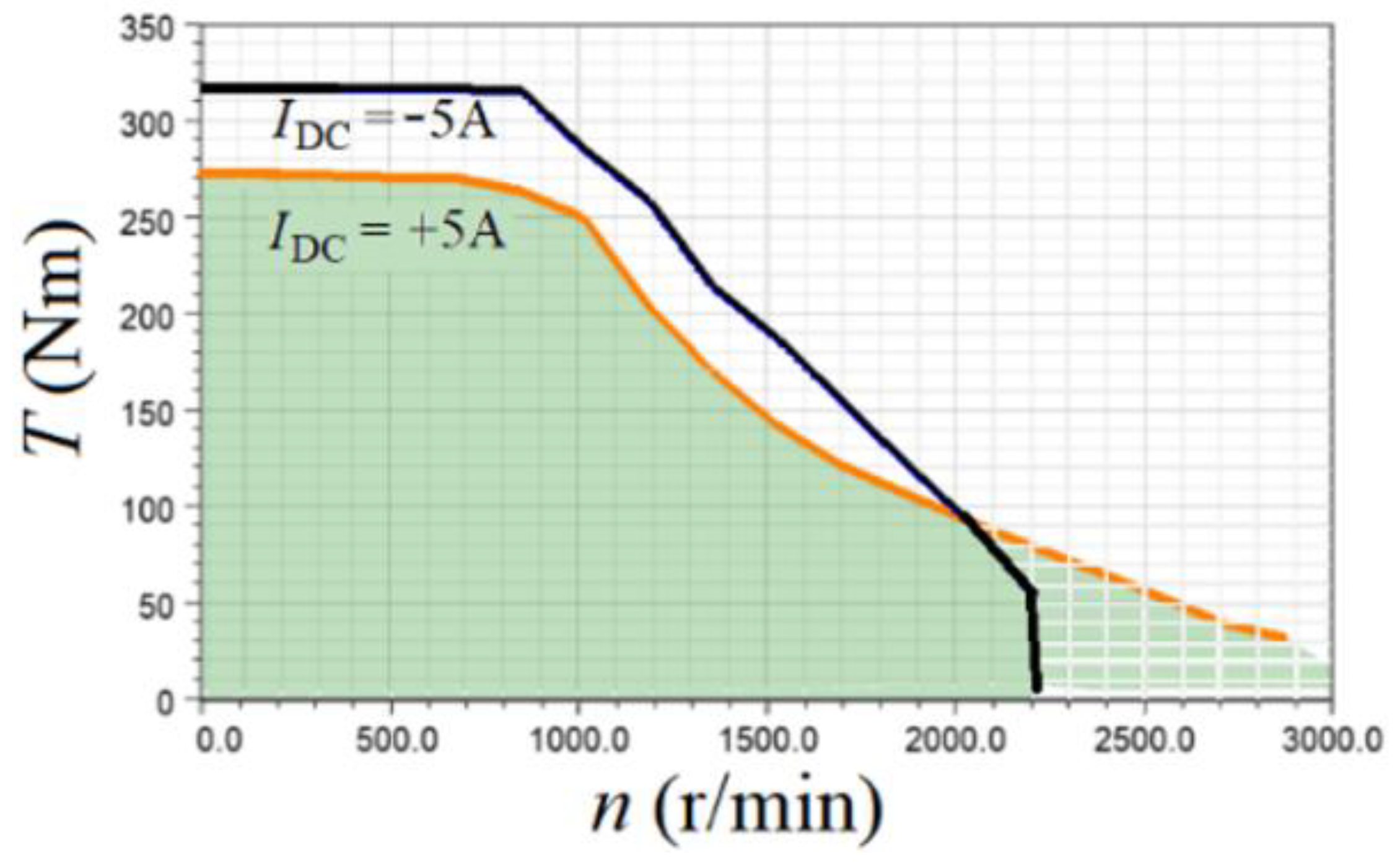
6. Performance of FCAFPMM
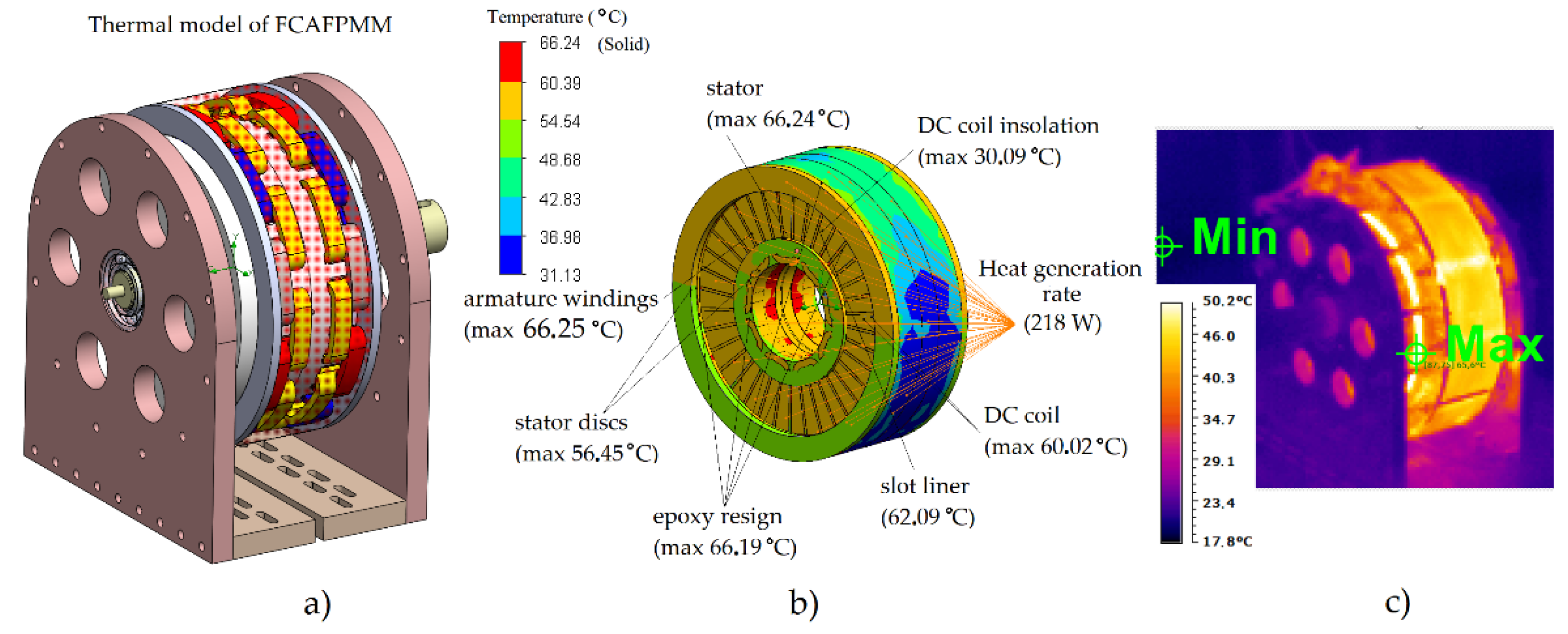
Based on the 3D FEA results, efficiency maps (Figure 10a–c) and total losses of the machine (Figure 10d–f) are calculated based on the mapping of core and windings losses, flux-linkage and torque as a function of the d- and q-axis currents and speed. The effect of additional field losses on the shape of the efficiency map is explored in specified conditions and limits: voltage power supply U = 200 Vrms; stator current Is ≤ 50 Arms; MTPA (maximum torque per ampere) control strategy; windings star connection; phase resistance Rf = 0.37 Ω.
It should be noted that, although the field-strengthening and weakening effect can be seen in Figure 10, additional sources of excitation increase additional losses. The consequent power loss density is high, and heat transfer is considered a challenge. This is particularly the case for high-speed operations in field-weakening regions when an additional source of excitation is activated.
Attention was also paid to the influence of additional DC field excitation on a startup torque and speed limit. Presented results show that magnetic field-strengthening with a DC coil current of IDC = −5 A increased startup torque by approximately 10%, and a value of electromagnetic torque of 320 Nm was reached. In field-weakening operations with a current of IDC = +5 A, the limit of speed was increased from 2500 rpm to 3500 rpm. In Figure 11, torque–speed curves of the machine calculated under DC coil currents of IDC = ±5 A are shown.

7. Thermal Analysis

Developing PM motors within a particular temperature limit is a key factor affecting the efficiency of the overall design. Based on the 3D thermal model of the machine without the cooling system presented in Figure 12a, steady-state and transient thermal analyses were carried out to evaluate the distribution of temperature in various parts of the stator. The model was mainly applied to predict the temperature rise in the stator (Figure 12b) of the machine. The temperature distribution was determined by considering convection from the back of stator core surfaces, air gaps, stator windings and epoxy resin surfaces. The heat sources, such as copper loss and stator core loss, were calculated using the 3D FEA transient method. In the first case study, the copper losses of 218 W in armature windings at an initial temperature of 40 °C were obtained through FE analysis. The losses were sent to CFD fluid–thermal analysis as heat sources, which correspond to copper losses of armature windings generated with a current density of J = 5 A/mm2. The thermal conductivity of copper windings and insulation, both with epoxy resin, were taken together in the slot for simplification of calculation.
Figure 12b presents the CFD calculation results of the stator at the rated load condition. As can be seen, the hottest spot at the highest temperature of 66.25 °C occurs in the middle of the stator core near the air gap of the machine. In the same current loading conditions, the experimental tests were performed mainly to verify simulation results, where a maximum temperature of 65.6 °C (Figure 12c) was clearly observed. During the test, the rotor was fixed and a thermal steady state of armature windings at the rated DC load conditions was reached.
It should be noted that the stator of the machine under transient conditions was designed to maintain all temperatures below class B insulation limits of a 120 °C hot spot. Hence, thermal transient curves for all parts of the stator were calculated and shown in Figure 13. In this case, total power losses of approximately 430 W were obtained at the rated operating point of the machine; this means that n = 750 r/min, Is = 12 A and IDC = 5 A (without a cooling system) were adopted for the calculation of the curves. The rated operating point as the starting point for the thermal analysis (pT1) is depicted in Figure 10c,f. The total losses consist of the copper losses in the armature AC windings 218.1 W, core losses in the stator 90.5 W and copper losses in the DC coil 121.2 W.
The results show that under the rated load conditions, all stator components will not be overheated. The maximal temperature of 97.8 °C was observed in the DC coil, and it was much below the limit.

8. Conclusions

In this paper, a design of a permanent magnet axial flux machine with iron poles and an additional DC coil was analyzed with detailed electromagnetic and thermal performance. Three-dimensional FEA results showed that flux control of the proposed machine in the range of approximately 50% was successfully obtained.
The paper evaluated torque and speed loops at a current of 50 A and a voltage of 200 V limits, where the maximum efficiency of 95% and the increased rotational speed control range of 0–3000 RPM were reached.
The temperature distribution of the presented machine model under the rated conditions was calculated based on fluid–thermal coupling analysis by CFD. The air cooling effectiveness of the CFD models was verified by experimental measurements on a prototype machine. Full thermal analyses and tests will be performed and presented in further publications.
Further scientific studies on the FCAFPMM machine will also be focused on optimizing the rotor pole geometry to reduce the cogging torque, which is particularly disadvantageous in the low-speed region while the magnetic flux is increased.

Author Contributions

Conceptualization, P.P. (Pawel Prajzendanc); Methodology, P.P. (Pawel Prajzendanc) and P.P. (Piotr Paplicki); Supervision, P.P. (Piotr Paplicki); Writing—original draft, P.P. (Pawel Prajzendanc); Writing—review & editing, P.P. (Piotr Paplicki). All authors have read and agreed to the published version of the manuscript.

Funding

This research received no external funding.

Institutional Review Board Statement

Not applicable.

Informed Consent Statement

Not applicable.

Data Availability Statement

Study did not report any data.

Conflicts of Interest

The authors declare no conflict of interest.

References

  1. Nedjar, B.; Hlioui, S.; Lecrivain, M.; Amara, Y.; Vido, L.; Gabsi, M. Study of a new hybrid excitation synchronous machine. In Proceedings of the XXth International Conference on Electrical Machines 2012, Marseille, France, 2–5 September 2012; pp. 2927–2932. [Google Scholar] [CrossRef]
  2. Gieras, J.F. PM synchronous generators with hybrid excitation systems and voltage control Capabilities: A review. In Proceedings of the XXth International Conference on Electrical Machines 2012, Marseille, France, 2–5 September 2012; pp. 2573–2579. [Google Scholar] [CrossRef]
  3. Wardach, M.; Palka, R.; Paplicki, P.; Prajzendanc, P.; Zarebski, T. Modern Hybrid Excited Electric Machines. Energies 2020, 13, 5910. [Google Scholar] [CrossRef]
  4. Geng, W.; Zhang, Z.; Jiang, K.; Yan, Y. A New Parallel Hybrid Excitation Machine: Permanent-Magnet/Variable-Reluctance Machine with Bidirectional Field-Regulating Capability. IEEE Trans. Ind. Electron. 2015, 62, 1372–1381. [Google Scholar] [CrossRef]
  5. Andrada, P.; Blanqué, B.; Martinez, E.; Torrent, M. A Novel Type of Hybrid Reluctance Motor Drive. IEEE Trans. Ind. Electron. 2014, 61, 4337–4345. [Google Scholar] [CrossRef]
  6. Zhao, W.; Shen, H.; Lipo, T.A.; Wang, X. A New Hybrid Permanent Magnet Synchronous Reluctance Machine with Axially Sandwiched Magnets for Performance Improvement. IEEE Trans. Energy Convers. 2018, 33, 2018–2029. [Google Scholar] [CrossRef]
  7. Zhao, X.; Niu, S.; Zhang, X.; Fu, W. Design of a New Relieving-DC-Saturation Hybrid Reluctance Machine for Fault-Tolerant In-Wheel Direct Drive. IEEE Trans. Ind. Electron. 2020, 67, 9571–9581. [Google Scholar] [CrossRef]
  8. Luo, X.; Lipo, T.A. A synchronous/permanent magnet hybrid AC machine. IEEE Trans. Energy Convers. 2000, 15, 203–210. [Google Scholar] [CrossRef] [Green Version]
  9. Xia, Y.; Yi, X.; Wen, Z.; Chen, Y.; Zhang, J. Direct Torque Control of Hybrid Excitation Permanent Magnet Synchronous Motor. In Proceedings of the 2019 22nd International Conference on Electrical Machines and Systems (ICEMS), Harbin, China, 11–14 August 2019; pp. 1–5. [Google Scholar] [CrossRef]
  10. Fodorean, D.; Djerdir, A.; Viorel, I.-A.; Miraoui, A. A Double Excited Synchronous Machine for Direct Drive Application—Design and Prototype Tests. IEEE Trans. Energy Convers. 2007, 22, 656–665. [Google Scholar] [CrossRef]
  11. Paplicki, P. Influence of Magnet and Flux-Barrier Arrange-ment on Flux Control Characteristics of Hybrid Excited ECPMS-machine. Elektron. Ir Elektrotechnika 2017, 23, 15–20. [Google Scholar] [CrossRef] [Green Version]
  12. Paplicki, P.; Palka, R.; Wardach, M.; Prajzendanc, P.; Mognaschi, M.E. Hybrid excited electric machine with axial flux bridges. Int. J. Appl. Electromagn. Mech. 2019, 59, 703–711. [Google Scholar] [CrossRef] [Green Version]
  13. May, H.; Meins, J.; Canders, W.R.; Pałka, R. New permanent magnet excited synchronous machine with extended, stator fixed auxilary excitation coil. In Proceedings of the XIV International Symposium on Electromagnetic Fields in Mechatronics, Electrical and Electronic Engineering, Arras, France, 10–12 September 2009. [Google Scholar]
  14. Liwen, L.; Hongmei, L.; Zhiwei, C.; Tian, Y.; Rundong, L.; Jingkui, M. Design of a Hybrid Excited Permanent Magnet Machine with AC Field Winding Excitation. In Proceedings of the 22nd International Conference on Electrical Machines and Systems (ICEMS), Harbin, China, 11–14 August 2019; pp. 1–4. [Google Scholar] [CrossRef]
  15. Gao, Y.; Li, D.; Qu, R.; Fan, X.; Li, J.; Ding, H. A Novel Hybrid Excitation Flux Reversal Machine for Electric Vehicle Propulsion. IEEE Trans. Veh. Technol. 2018, 67, 171–182. [Google Scholar] [CrossRef]
  16. Wardach, M.; Bonislawski, M.; Palka, R.; Paplicki, P.; Prajzendanc, P. Hybrid Excited Synchronous Machine with Wireless Supply Control System. Energies 2019, 12, 3153. [Google Scholar] [CrossRef] [Green Version]
  17. Aydin, M.; Huang, S.; Lipo, T.A. Design, Analysis, and Control of a Hybrid Field-Controlled Axial-Flux Permanent-Magnet Motor. IEEE Trans. Ind. Electron. 2010, 57, 78–87. [Google Scholar] [CrossRef]
  18. Capponi, F.G.; De Donato, G.; Borocci, G.; Caricchi, F. Axial-Flux Hybrid-Excitation Synchronous Machine: Analysis, Design, and Experimental Evaluation. IEEE Trans. Ind. Appl. 2014, 50, 3173–3184. [Google Scholar] [CrossRef]
  19. Ostroverkhov, M.; Chumack, V.; Monakhov, E. Synchronous Axial-Flux Generator with Hybrid Excitation in Stand Alone Mode. In Proceedings of the 2019 IEEE 2nd Ukraine Conference on Electrical and Computer Engineering (UKRCON), Lviv, Ukraine, 2–6 July 2019; pp. 455–459. [Google Scholar]
  20. Chen, Z.; Zhou, N. Flux regulation ability of a hybrid excitation doubly salient machine. IET Electr. Power Appl. 2011, 5, 224–229. [Google Scholar] [CrossRef]
  21. Hou, J.; Geng, W.; Zhu, T.; Li, Q. Topological Principle and Electromagnetic Performance of a Novel Axial-Flux Hybrid-Excitation In-wheel Motor. In Proceedings of the 23rd European Conference on Power Electronics and Applications (EPE’21 ECCE Europe) 2021, Ghent, Belgium, 6–10 September 2021; pp. 1–8. [Google Scholar]
  22. Geng, W.; Zhang, Z.; Li, Q. Concept and Electromagnetic Design of a New Axial Flux Hybrid Excitation Motor for In-wheel Motor Driven Electric Vehicle. In Proceedings of the 2019 22nd International Conference on Electrical Machines and Systems (ICEMS), Harbin, China, 11–14 August 2019; pp. 1–6. [Google Scholar] [CrossRef]
  23. Hsu, J. Direct control of air-gap flux in permanent-magnet machines. IEEE Trans. Energy Convers. 2000, 15, 361–365. [Google Scholar] [CrossRef]
  24. Paplicki, P.; Prajzendanc, P. The influence of permanent magnet length and magnet type on flux-control of axial flux hybrid excited electrical machine. In Proceedings of the 14th Selected Issues of Electrical Engineering and Electronics (WZEE), Szczecin, Poland, 19–21 November 2018; pp. 1–4. [Google Scholar] [CrossRef]
  25. Paplicki, P.; Prajzendanc, P.; Wardach, M.; Palka, R.; Cierzniewski, K.; Pstrokonski, R. Influence of Geometry of Iron Poles on the Cogging Torque of a Field Control Axial Flux Permanent Magnet Machine. Int. J. Appl. Electromagn. Mech. 2022, 1–5, in press. [Google Scholar]
Figure 1. Field-Controlled Axial Flux Permanent Magnet Machine (FCAFPMM) design.
Energies 15 02733 g001
Figure 2. FCAFPMM’s rotor (a), dimensions of rotor’s disc with magnets and iron poles (b).
Energies 15 02733 g002
Figure 3. Idealized magnetic flux distribution in FCAFPMM at DC coil current IDC = 0 (a), IDC −5 A (b) and IDC +5 A (c).
Energies 15 02733 g003
Figure 4. Air-gap magnetic flux density at the different magnetic field distributions IDC = 0, Is = 0 (a), IDC = ±5 A, Is = 0 (b) and IDC = −5 A, Isd = 70.7 A (c).
Energies 15 02733 g004
Figure 5. Air-gap magnetic flux density at the different magnetic field distributions in the model without PMs at DC coil current IDC+ (a) and IDC− (b).
Energies 15 02733 g005
Figure 6. Magnetic flux density distribution on the 3-D FEA model (a) and in the middle of the air gap of the machine (b).
Energies 15 02733 g006
Figure 7. No-load phase voltage characteristics for three cases of IDC current load.
Energies 15 02733 g007
Figure 8. Electromagnetic torque waveforms versus rotor position under different stator currents for three IDC current excitations IDC −5 A (a), IDC = 0 A (b) and IDC +5 A (c).
Energies 15 02733 g008
Figure 9. Maximum electromagnetic stator torque characteristics at the different control coil currents.
Energies 15 02733 g009
Figure 10. Maps of machine efficiency (ac) and total losses (df) for three IDC current excitations.
Energies 15 02733 g010
Figure 11. Torque–speed envelopes compared under different DC coil currents, at DC coil current IDC = −5 A (black line—field-strengthening operation region) and IDC = +5 A (orange line—field-weakening operation region).
Energies 15 02733 g011
Figure 12. Three-dimensional thermal model of FCAFPMM (a); 3D FEA results of thermal distribution on the stator (b); thermal imaging result (c).
Energies 15 02733 g012
Figure 13. Heat characteristics.
Energies 15 02733 g013
Publisher’s Note: MDPI stays neutral with regard to jurisdictional claims in published maps and institutional affiliations.

