Abstract
This study presents a fast terminal synergetic control (FTSC) scheme to investigate the nonlinear control problem of permanent magnet vernier generator (PMVG)-based variable-speed wind energy conversion systems (WECSs). In wind turbines, better speed tracking and fast dynamic behavior is required to achieve the maximum power extraction. To do this, the FTSC method is firstly proposed to improve the dynamic performance of tracking the speedby, addressing the turbulent wind and uncertainties in the PMVG system, which improves the wind energy extraction efficiency and alleviates mechanical stress over the turbine. Next, the closed-loop FTSC with a macro variable and novel reaching law is presented to enhance the convergence of the speed error signal when it is far from equilibrium in finite time. At this time, the controller’s output is a zero chattering generator torque reference that can operate the system in both below- and above-rated wind conditions, in addition to pitch control. Then, the proposed control method is verified for its effectiveness in energy capture through numerical simulation and experimental verification of a 5 kW direct drive PMVG-based WECS. Finally, comparative results confirm the better performance of the proposed system under transients than other controllers considered in this analysis.
1. Introduction
Over the years, non-renewable sources have been mainly used for electricity production, which are highly polluting and significantly contribute to global warming [1]. Hence, to achieve sustainable development, electricity production has shifted primarily from fossil fuels to renewable energies [2]. Moreover, as of 2020, the share of renewable energy in global electricity production has increased to 29%, up from 27% in 2019 [3]. In particular, in 2020, the installed capacity of wind energy conversion systems (WECS) around the globe increased significantly, reaching an impressive result of 743 GW [4]. Moreover, the electricity generated by wind power is much cheaper [5]. Additionally, to improve power generation in WECSs, variable-speed (VS) WECS is the preferred choice because of its cost-effectiveness and ease of maintenance [6].
Generally, the output power from a wind turbine (WT) is converted to electricity by generators with a combination of converter systems. There are many generator types available to use with WECS; the squirrel cage induction generator (SCIG) used with WECS requires a total capacity converter to regulate the operating speed for extracting the maximum available power from the wind [7]. Further, the doubly fed induction generator (DFIG) has been preferred for wind generation applications. Its merits include reduced power rating for converters, high ratio of performance–price, wide operational speed range, variable-speed operation, and full power control capability [8]. Though there are inherent merits in favor of DFIG, it also suffers difficulty in excitation to the rotor circuit. Moreover, the gearbox requirement for speed conversion entails audible noise, regular maintenance, and low reliability [9]. Alternatively, synchronous generators have been designed with a higher number of poles operated with the speed of the wind turbine rotor, known as the direct drive (DD) system. Such a DD system does not need any gearbox [10]. Hence, nowadays, the permanent magnet synchronous generator (PMSG) has become the most popular choice among WT manufacturers, and has the potential to ensure better wind energy conversion efficiency throughout its operating range. Moreover, full-capacity converters can support lead/lagging reactive power control and fault ride-through operation without any additional equipment. Furthermore, it can be set up to run across various grid codes [11]. Thus, it is expected that future projects will use PMSGs with up to 15 MW rating for wind power generation [12].
Most recently, the permanent magnet vernier generators (PMVGs) with outer rotors have been designed with a higher value of torque density and are emerging as a substitute to conventional PMSGs [13]. Regarding the design of PMVGs, the optimized dimension and location of modulator poles significantly improve the induced voltage, reduce the cogging torque, and minimize the total production cost [14]. Additionally, from a comparative analysis of permanent magnet (PM) machines, it is evident that PMVGs can achieve better torque density than PMSGs. Furthermore, the authors in [15] have conducted a detailed system-level investigation on PMVGs made for a range of power ratings from fractional MW to multi MW, revealing various parametric comparisons and structural data. As a consequence of this, PMVG will be very suitable for multi-MW wind energy systems, with significant savings in structural mass and total cost [16]. In this regard, there is only minimal literature concentrating on a more comprehensive investigation of PMVG topology in a WT application. Hence, this study presents an effective control scheme to investigate the nonlinear control problem of PMVG-based WECS.
On the other hand, the DD synchronous generator-based WECS has a wide range of operating speeds and does not require any electrical excitation [17]. Moreover, it runs with better performance and has an excellent range of operating speed over other electrical generators [18]. Thus, there are numerous control schemes available in the literature regarding the maximum extraction of available wind energy based on wind speed. The hill climb search (HCS) algorithm for maximum power extraction (MPE) is widely used in wind energy applications because of its simplicity and flexibility [19]. However, it suffers the drawback of the possible wrong direction of operation to obtain the maximum power under a highly fluctuating, rapid variation in wind speed [20]. Further, the optimum relation-based MPE operates without speed measurement or a lookup table [21]. However, it requires details of the relationship between the turbine power and converter current [22]. Moreover, the incremental conductance algorithm, with its merits of handling nonlinearity and easy implementation, also suffers instability under variable-speed operation [23]. Fathabadi [24] has presented MPE methods such as optimum torque control (OTC) and tip speed ratio (TSR) control, which are the preferable industrial standard control methods for VS WECS under various wind conditions. Following this, the OTC control technique attempted to calculate the torque reference to the generator with the rotor speed information and operate the system for MPE [25]. This method is simple, faster in operation, reliable, and a straightforward control technique, but it is still inefficient for a dynamic response during highly fluctuating wind speed conditions [26]. To overcome this issue, the TSR-based control methods are used with rotor speed information and the measured wind speed. In this case, the reference speed is calculated from wind velocity information for MPE operation and compared with the actual rotor speed to produce an error signal. As a result, the error signal is further used with fast-converging tracking controllers to improve the dynamic behavior of WECS in speed tracking [27]. Additionally, the TSR-based MPE controllers have the merit of better dynamic performance [28]. Moreover, they were found to be better suited for highly fluctuating wind speeds because of their excellent tracking capability [29].
Moreover, regarding reference tracking, the feedback proportional–integral (PI) controller has been widely used in TSR control because of its inherent ability to reduce steady-state error at a faster rate. The error convergence of the PI controller is mainly due to the addition of a pole at the origin; as a consequence of this, the PI controller suffers the problem of overshoot and instability during transient operation; in addition, the tracking response has a considerable settling time [30]. Since the WT system has to operate with random fluctuations in wind speed, the overshoot and oscillatory nature of the PI speed controller induce severe mechanical stress over the blades of WTs; this needs to be addressed to reduce the fatigue load on turbine blades. A fractional-order PI (FOPI) controller can eliminate the overshoot problem and notably improve the dynamic behavior for industrial control applications by providing adjustable time and frequency responses [18]. However, it is still noteworthy that the fractional-order terminal sliding mode controllers (SMCs) provide better control action than the FOPI controller for MPE applications wherever power electronic interfaces are used. The terminal attraction principle used here has the advantages of finite convergence to zero error [31]. However, in SMC, suppression of chattering phenomena ia a key issue, and it requires special attention [32]. Moreover, the terminal synergetic approach used in [33] gives chattering free control with rapid convergence of error. In this respect, it is observed that a synergetic control with an improved macro variable can reduce the chattering phenomenon when applied to MPE operation with power converters. In addition, it necessitates simple mathematical calculations, as in [34].
Motivated by the above, in this study, a fast terminal synergetic controller (FTSC) is designed for the PMVG-based WECS while considering the nonlinear behavior of WT aerodynamics. By utilizing the tracking error of speed, the proposed FTSC improves the dynamic performance of rotor speed and significantly improves the power extraction efficiency of WECS. Moreover, the proposed control method considerably reduces the mechanical stress over the rotating shaft and turbine blades as compared to other conventional methods and thus effectively eliminates the rotor speed oscillations and turbine fatigue. Thus, the overall contribution of this study is summarized as follows:
- The FSTC is presented with an integral macro variable to track the operating speed of PMVG to the optimum reference speed given by the TSR-based MPE scheme in MSC.
- The closed-loop FTSC with a macro variable and novel reaching law is presented to enhance the convergence rate of the error signal in finite time. Then, a zero chattering torque reference is generated to operate the system below and above rated wind conditions.
- The proposed method is validated by implementing it in the speed control loop of a 5 kW PMVG-based WECS in a simulation and experimental setup for two different wind speed conditions.
- Finally, the performance evaluation of the proposed FTSC is compared with conventional OTC and PI controllers [24] by analyzing the power extraction efficiencies of the PMVG-based WECS.
The rest of the paper is organized as follows. Section 2 deals with the modeling of the PMVG-based WECS. The design procedure of FTSC with a macro variable and reaching law is explained with the PMVG-based WECS in Section 3. Simulation and experimental results are presented in Section 4, followed by the power extraction efficiency analysis in Section 5. Finally, Section 6 concludes the findings of this study.
2. Wind Turbine Modeling
The aerodynamic power extracted by wind turbine can be modeled as
where is air density, is wind speed, and is blade rotor swept area. Here, R is the radius of the WT. Power coefficient is a function of blade pitch angle and tip speed ratio (TSR) , which is defined as
Here, the mechanical angular speed of a turbine is denoted by . With a variable pitch angle , power coefficient of WT can be approximated with the following exponential mathematical expression [35].
is given as follows.
Here, Figure 1 depicts the nonlinear relationship of and , from which it is observed that of the wind turbine converges to the maximum value () of only with a unique value () of , satisfying the pitch angle as 0. Hence, from (1) and (2), the extraction of maximum power can be achieved by tracking the operating speed to keep at its optimum value .
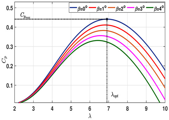
Figure 1.
relationship of a typical WECS for varying pitch angle (3).
The single lumped mass model of the DD PMVG system describes the shaft dynamics as follows.
where and are aerodynamic and electromagnetic torques, respectively. is the combined inertia of the entire rotating mass, which includes the rotating part of the turbine and PMVG, and B is the net friction coefficient of the rotating shaft.
Dynamical Modeling of PMVG
Dynamical modeling of PMVG can be described in the synchronously rotating reference frame as follows:
where and are frame stator voltages, represents the winding resistance of the stator, and and represent frame stator currents, respectively. The electrical rotating speed of generator is the product of generator pole pair and mechanical angular speed. and are the frame inductance of the generator, and the modulation flux linkage is expressed as . Then, is the electromagnetic torque of PMVG.
3. Maximum Power Extraction Control Techniques for VS WECS
The power extraction efficiency of VS WECS can be improved under below-rated wind speed conditions by tracking the rotor speed to an optimum value. Usually, pitch angle is set to zero, and by keeping to its optimum value under an effective speed tracking system, power coefficient can be maintained at its maximum value to ensure better power capture from available wind energy. Operation of WECS at the optimum point is ensured by forcing the generator to follow the trajectory of MPPT for varying wind velocity, as shown in Figure 2.
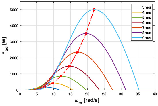
Figure 2.
MPPT trajectory in characteristics of 5 kW WECS.
3.1. Conventional Optimum Torque Control Scheme
The OTC method is an industry-standard baseline control scheme extensively used in commercial VS WECS for MPPT under region II operation. It has an inherent feature of simplicity, easy maintenance, robust control nature, and it does not require information about wind speed.
From (4), the torque and rotor speed relationship can be deduced as follows.
From (6), for an increase in wind velocity, ’s value increases; in consequence, the turbine is accelerated to reach a new equilibrium point for a reduction in wind velocity; the opposite happens, which results in a deceleration of rotor speed. Hence, from (6), it is observed that by providing a suitable value to , the generator can be forced to operate at optimum speed and optimum TSR to strictly converge the value of to [36]. Then, by achieving optimal TSR, the system will be kept in the locus of MPPT and the extracted value of turbine aerodynamic power () can be expressed as a function of rotor speed [37]:
where:
Then, the torque reference for the generator can be deduced as
The control input (8) to PMVG seemingly converges to its maximum value and ensures the maximum power extraction operation.
3.2. Synergetic Control
By direct calculation of optimum rotor speed () from the information of the measured wind speed, the response of the system for convergence to can be further improved by utilizing a speed tracking controller [38]. Hence, for an effective power extraction operation with speed tracking, a reference tracking controller is required to converge the speed tracking error to zero.
where is the optimum reference speed calculated from . A macro variable , as a linear combination of system states, is required to be considered for synergetic control [39], which can be expressed as follows:
where is a positive constant. Then, the dynamic behavior of the macro variable can be expressed as follows:
where the operator decides the speed of convergence of error. From (10), the derivative of can be written as
Then, by substituting (4) in (13) and deducing the dynamics of control variable , the following control law can be obtained:
Above, Equation (14) gives the approaching control input, which will force the rotor speed to the reference speed. Further, a switching law can be added to the control input to maintain dynamic motion in zero error state [40]. The following equation gives the equivalent control input with switching law:
where and Q are positive constants of value higher than uncertainties, and satisfies the following conditions:
Control input (15) gives synergetic control for a DD PMVG-based WECS, which has the potential to track the reference speed of the rotor in a finite convergence time.
3.3. Fast Terminal Synergetic Control
The FTSC scheme guarantees fast convergence with terminal attraction. The dynamics of the modified macro variable with an integral term are defined as follows:
where , and (p and q are positive integers).
We consider the following dynamics of macro variable :
The time derivative of (16) can be obtained as follows:
By substituting (20) into (17) and deducing , the dynamics of the control variable can be obtained as follows:
Equation (21) depicts the control input, which converges the rotor speed to the reference value. Further, by incorporating a switching law into the control input, the following equation is obtained for the equivalent control input of FTSC:
The schematic depiction of the proposed FTSC for the PMVG-based VS WECS is given in Figure 3.
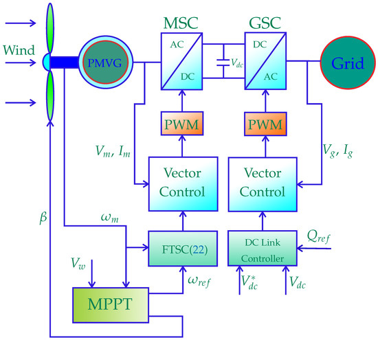
Figure 3.
Block diagram of the proposed control scheme for PMVG-based WECS.
Further, the stability of the proposed control scheme (22) is validated by using the following Lyapunov function:
By taking the time derivative of (23), we can obtain the following:
Substituting (17) into (24), we can obtain
Equation (25) is written as follows:
The solution to (26) is
where is the initial value of the Lyapunov function at , and the solution of exponential Equation (27) ensures the finite time stability of the proposed FTSC scheme.
4. Performance Evaluation by Simulation and Experimentation Results
In this section, the proposed scheme is validated by executing MATLAB/Simulink simulation and experimental verification in a laboratory setup for a 5 kW DD PMVG-based WECS. The parameters used for the test setup are given in Table 1. A step-varying and two different cases of randomly varying wind profiles of distinct mean value are considered to validate the proposed method’s performance compared to conventional control methods.
A pattern of step and two cases of random wind profile are depicted in Figure 4, Figure 5 and Figure 6, respectively. Under the randomly varying cases, in case-I, a wind profile of mean value 8 m/s is considered, which does not pass beyond the rated wind velocity at any instant, and the wind velocity turbulently fluctuates within the range of 6 m/s to 9 m/s, as shown in Figure 5. Under this condition, the WECS is required to be operated only in region I by keeping pitch angle as . Moreover, in case-II, the mean value of wind speed is taken as 9 m/s, and it fluctuates randomly around the mean value within the range of m/s and m/s, as shown in Figure 6. Therefore, the WTs must be operated in both regions II and III. Consequently, to operate the turbine at the required pitch angle, a typical PI-type pitch controller, as shown in Figure 7, is used for both the simulation and experimental validation setup for region III operation, as in [41].
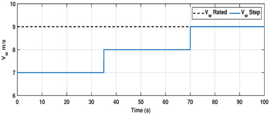
Figure 4.
Step-varying wind profile used for region II operation.
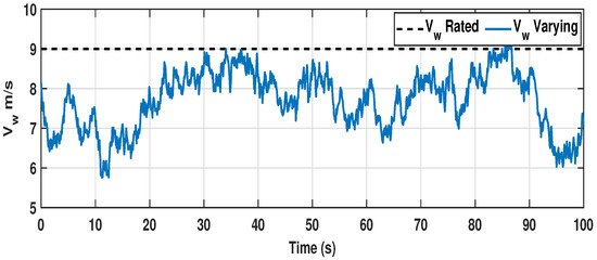
Figure 5.
Random wind profile with mean value of 8 m/s for region II operation.
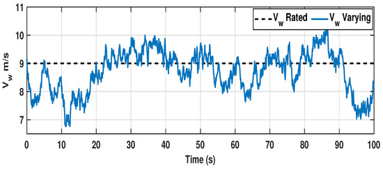
Figure 6.
Random wind profile with mean value of 9 m/s for region II and III operation.

Figure 7.
Conventional pitch control scheme for region III operation in PMVG-based WECS.
4.1. Simulation Results for Step Change in Wind Speed
In this subsection, a simulation study is conducted in comparison with well-established industry-standard OTC- and TSR-based PI controllers to substantiate the efficacious nature of the proposed FTSC control method. Then, the results are taken to verify the constructiveness of FTSC considering the rate of convergence of its power coefficient to its maximum possible value. From the literature study, faster reference speed tracking is imperative to achieve a better convergence rate under transient operation. Hence, by evaluating the performance of the proposed FTSC in comparison with the OTC controller and TSR-based PI speed controller for a step change in wind speed, the caliber of FTSC can easily be understood. The step wind profile considered here has a sudden unit change in wind speed at instant of 35 s and 70 s, as given in Figure 4.
For the given wind velocity, is the optimal rotor speed that needs to be tracked for maximizing power extraction under step-varying wind conditions. Since the DD PMVG system has a definite mechanical time constant considering its combined mass of rotor blades and moving parts, there is a considerable rise time in achieving the reference speed during the transient stage. From Figure 8, we can confirm that the convergence rate of to the optimum value under the FTSC scheme is 3 s, which is 1.5 s faster than the conventional OTC and TSR-based PI control schemes. Moreover, it can be noted that the response of under the proposed scheme has minimal undershoot when compared to other controllers. From the dynamics of (2), the fast convergence of to its optimum value significantly improves the response of TSR () by quickly reaching its optimum value , as displayed in Figure 9. As a result, from Figure 10, it can be observed that the power coefficient is rapidly attaining its maximum value compared to other conventional methods. As a consequence, the dynamic response of aerodynamic power extraction under the transient condition is notably increased in the proposed FTSC scheme when compared to other control methods, as shown in Figure 11. From this, it is evident that the proposed FTSC scheme has better viability than OTC and PI speed controllers for maximum power extraction in a PMVG-based WECS.
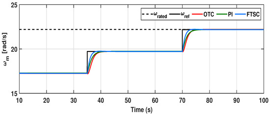
Figure 8.
Dynamic response of rotor speed under the proposed FTSC scheme in comparison with OTC and PI controllers under step wind profile.
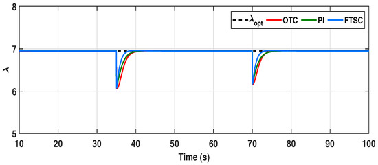
Figure 9.
Comparative evaluation of tip speed ratio () under step wind profile.
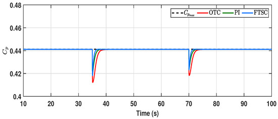
Figure 10.
Comparative evaluation of power coefficient () under step wind profile.
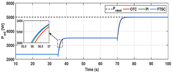
Figure 11.
Aerodynamic power captured by the WECS under different control schemes for step wind profile.
4.2. Simulation Results for Random Change in Wind Speed (Case-I)
The purpose of this subsection is to validate the performance of the proposed FTSC scheme with a randomly varying turbulent wind profile, as presented in Figure 5. Further, the simulation results for the FTSC method and the performance of the OTC- and TSR-based PI speed controllers present an impression of power extraction productivity. As seen in Figure 12, it can be observed that the proposed FTSC can rapidly track the rotor speed reference required for the MPPT operation. Despite the large combined inertia of the rotating system, the proposed FTSC scheme has marginally better tracking ability than other control schemes for the better tracking of the optimal reference speed. As a result, the TSR () for the proposed FTSC scheme has a minimal deviation ranging from to around the , as depicted in Figure 13. Meanwhile, for other control schemes, it is in the range of to , which is considerably far from the .
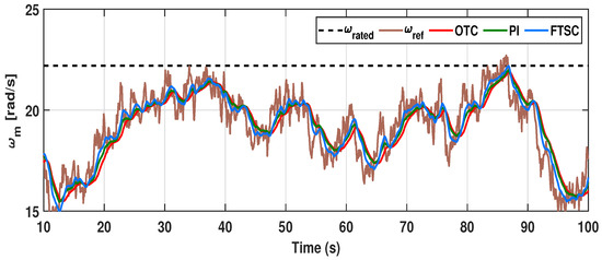
Figure 12.
Dynamic response of rotor speed under proposed control scheme in comparison with OTC and PI controllers for varying wind profile case-I.
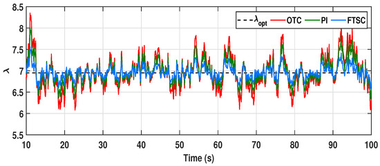
Figure 13.
Comparative evaluation of tip speed ratio () for varying wind profile case-I.
Further, the value of is predominantly kept near for the entire duration of operation; as a result, it is seen that the power coefficient is improved under the proposed FTSC control scheme, whose minimum value under the proposed scheme accounts for , and for other methods, it further comes down to , as seen in Figure 14. Consequently, the electromagnetic torque tracking capability of the proposed control scheme is compared with the OTC- and TSR-based PI control methods. As seen in Figure 15, it is evident that the proposed FTSC can efficiently track the optimum torque reference under varying wind conditions over existing control schemes. As a result, from Figure 16, we can confirm that the proposed control scheme significantly improves the aerodynamic power extraction performance of the PMVG-based WECS under varying wind conditions. Thus, from the results, the productiveness of the proposed scheme is verified for power extraction efficiency over existing OTC and TSR-based PI control schemes. However, it is quite significant to distinguish the potential of the proposed system to track the MPPT trajectory under randomly varying wind conditions with other control methods considered in this study.
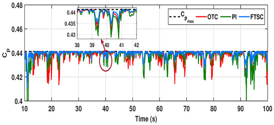
Figure 14.
Power coefficient () comparison of different control schemes under varying wind profile case-I.
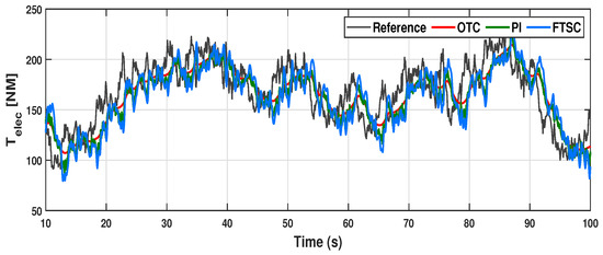
Figure 15.
Comparative analysis of under the control schemes discussed for varying wind profile case-I.
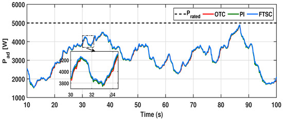
Figure 16.
Aerodynamic power captured by the WECS under different control schemes for varying wind profile case-I.
Therefore, and data from simulation results under different control schemes are retrieved and exercised to form a line of trace in ascending order. Then, the trace line is superimposed onto the MPPT trajectory in the plane for varying wind speed, as displayed in Figure 17 [42]. From this, it is manifested that the proposed FTSC scheme has better tracking performance over the trajectory in comparison with other controllers discussed in this study.
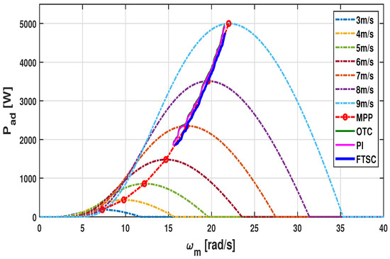
Figure 17.
MPP trajectory tracking performance comparison for varying wind profile case-I.
4.3. Simulation Results for Random Change in Wind Speed (Case-II)
Further, to examine the proposed control scheme under varying wind speed fluctuating around the rated value, as seen in Figure 6, here, the operation of the PMVG-based WECS is required to switch between regions II and III. In the meantime, rated power extraction operation above 9 m/s of wind velocity is ensured by the action of the pitch controller in region III. The pitch system’s actuation is inherently based on the rotor speed, particularly above the rated wind speed. By principle, the system will try to regulate the rotor speed at the rated value by initiating pitch actuation whenever the rotor speed goes beyond the rated value. Since the rotor speed tracking efficacy depends on the controller performance, the initiation of pitch actuation for a better control scheme begins ahead of other control schemes.
From this perspective, the performance of the proposed control scheme can be observed from the dynamic response of , as illustrated in Figure 18. In this respect, the rotor speed response of the proposed scheme reaches a rated value of rad/s well in advance of other conventional controllers, which proves the merits of the proposed FTSC scheme. Moreover, due to the better dynamic behavior of under the proposed FTSC, the power captured by the wind turbine is significantly increased as compared to other schemes, as displayed in Figure 19. Moreover, the initiation of the pitch actuation signal depicted in Figure 20 for region III operation unveils the advancement in pitch actuation, further strengthening the claim of the merits of the FTSC scheme for power extraction efficiency.
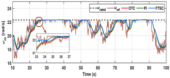
Figure 18.
Dynamic response of rotor speed under proposed system in comparison with OTC and PI controllers for varying wind profile case-II.
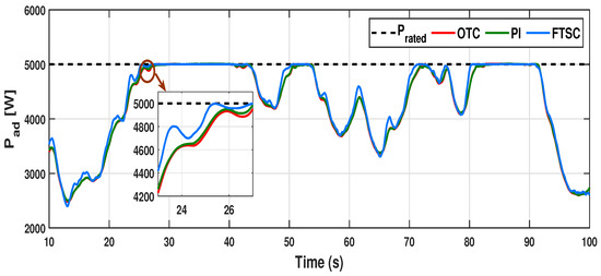
Figure 19.
Aerodynamic power captured by the system under different control schemes for varying wind profile case-II.
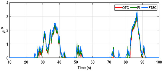
Figure 20.
The pitch angle () regulation signal given to the actuator for region III operation under varying wind profile case-II with different control schemes.
4.4. Experimentation Results for Random Change in Wind Speed (Case-I)
In this section, the validity of the proposed control method is verified with a 5 kW laboratory prototype of a PMVG-based WECS, as shown in Figure 21. A direct torque-controlled, 6-kW, 220 V/60 Hz, 300 rpm, variable-speed Siemens induction motor driven by a Sinamics-S120 power controller interfaced to National Instruments LabVIEW, which emulates the behavior of wind turbine, is used, which also includes the pitch actuation system. The wind profiles shown in Figure 5 and Figure 6 with time stamping were loaded into the LabVIEW interface and used to operate the induction motor as per the dynamics in (1)–(3). Further, the parameters of a PMVG-based WECS are given in Table 2, as similarly presented in [43]. In parallel, the FTSC control strategy is implemented using a Texas Instruments TMS320F28335 10 kHz DSP control board to operate the PMVG as per the information of the wind profile. A back-to-back voltage source controller, shown in block diagram Figure 3, with a DC link voltage of 350 V interconnects the utility grid and generator; the grid voltage/frequency is 220 V/60 Hz. Further, the rotor position and speed are measured by pulse encoders with 5 V dc pulses and the resolution is 600 counts/rev. The parameters of the machine are given in Table 1.

Table 1.
Experimental setup parameters [43].
Table 1.
Experimental setup parameters [43].
| 10 | 0.4 | mH | wb | 415 F |

Table 2.
Parameters of PMVG-based WECS [43].
Table 2.
Parameters of PMVG-based WECS [43].
| R | B | ||||
|---|---|---|---|---|---|
| 5 kW | 1.225 kg/m | m | 7 | N.m.s |
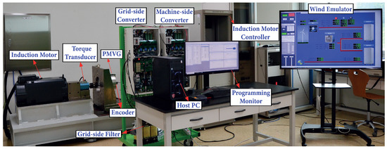
Figure 21.
Overall configuration of 5 kW PMVG-based WECS lab experimental setup [43].
The experimental dynamic responses of the PMVG-based WECS under the proposed and other control schemes with varying wind profile case-I are given in Figure 22 and Figure 23. From Figure 22a, we can see that, regarding the experimental response of rotor speed under different control methods, the speed in the proposed method converges to the optimum speed at a faster rate as compared to other methods, and the comparative plot of the respective TSRs of each of the control schemes is provided in Figure 22b. Further, the improvement in power coefficient is shown in Figure 22c. In addition, the improvement in extracted aerodynamic power is demonstrated in Figure 23a, while Figure 23b confirms the tracking performance of the proposed control input . As a result, from Figure 23c, it is observed that the proposed control method greatly enhances the output power delivered to the utility grid.
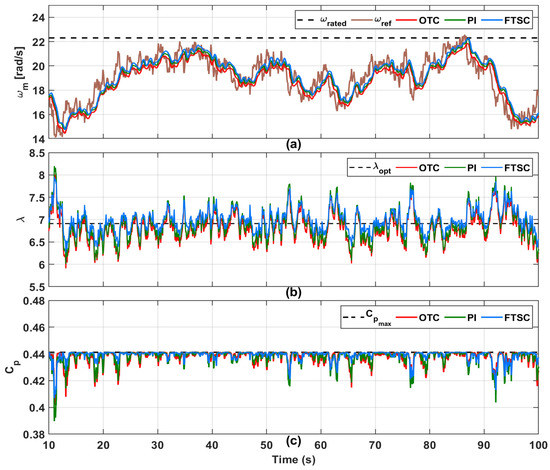
Figure 22.
Experimental results for dynamic response comparison of PMVG-based WECS for varying wind profile case-I. (a) Rotor speed. (b) Tip speed ratio. (c) Power coefficient under proposed control system in comparison with OTC and PI control methods.
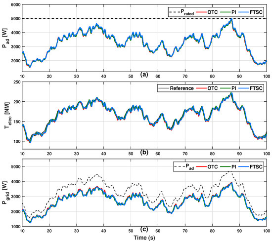
Figure 23.
Experimental comparative evaluation of PMVG-based WECS under varying wind profile case-I. (a) Aerodynamic power. (b) Electromagnetic torque. (c) Power transfer to utility grid.
4.5. Experimentation Results for Random Change in Wind Speed (Case-II)
For randomly varying wind speed above the rated value, frequent pitch actuation is essential, and the system is required to frequently shift between MPPT (region II) and constant power operation (region III). The experimental dynamic responses of the PMVG-based WECS under the proposed and other control schemes with varying wind profile case-II are given in Figure 24 and Figure 25. The speed response of the proposed system is given in Figure 24a, followed by the tip speed ratio and power coefficient as shown in Figure 24b,c. Under region III operation, due to the activation of pitch control, the is reduced by up to 0.34 as per the dynamics given in (3); hence, the output power is kept constant at the rated value, as shown in Figure 25a. Following this, the control input and power transfer to the electric grid are depicted in Figure 25b,c, respectively. Moreover, Figure 26 exhibits the pitch actuation signals for region III operation. From the results, it is evident that the power extraction under the proposed FTSC scheme is considerably improved under MPPT operation in region II of the PMVG-based WECS as compared to other conventional schemes.
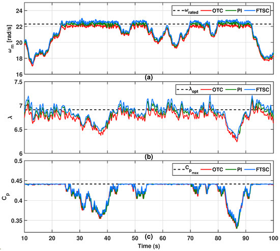
Figure 24.
Experimental results for dynamic response comparison of PMVG-based WECS under varying wind profile case-II. (a) Rotor speed. (b) Tip speed ratio. (c) Power coefficient under proposed system in comparison with OTC and PI control methods.
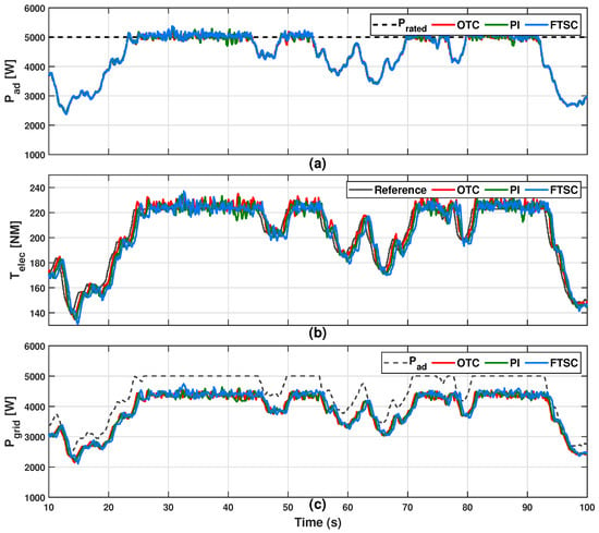
Figure 25.
Experimental comparative evaluation of PMVG-based WECS under varying wind profile case-II. (a) Aerodynamic power. (b) Electromagnetic torque. (c) Power transfer to utility grid.
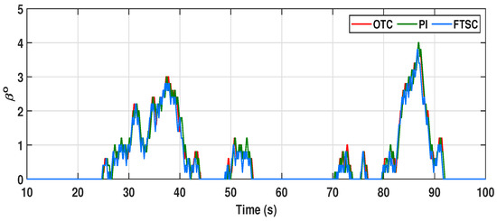
Figure 26.
Experimental results for pitch angle () regulation signal given to the actuator for region III operation under varying wind profile case-II with different control schemes.
5. Quantitative Analysis for Power Extraction Efficiency
In this section, quantitative performance analysis of the proposed controller with PMVG-based WECS is investigated in comparison with an OTC- and TSR-based PI speed controller. Moreover, the effectiveness of the proposed method is verified by comparing the MPPT performance with existing methods. The aerodynamic and electric power efficiency of a WECS can be calculated by using the following formula:
where is the optimal aerodynamic power.
The aerodynamic power extraction efficiency and electric power efficiency of a PMVG-based WECS under two cases of wind profiles are given in Table 3. From this, we can confirm that the power extraction efficiency of the PMVG-based WECS for the proposed method is significantly higher than for the OTC- and PI-based speed control methods. Under a random wind profile with a mean value of 8 m/s, the proposed method has improved the power extraction efficiency to over the other two control methods. Moreover, the electric efficiency of the system under the proposed control scheme is marginally improved when compared to other conventional control methods. From the results, it is noted that, under the random wind profile of case-II, the system operates in both regions II and III. Following this, the aerodynamic and electric efficiencies are estimated as and , respectively, which is more significant than other control methods. Therefore, we can conclude that the proposed control method is superior to other control methods in terms of reaching time and maximum power extraction capability under various wind conditions.

Table 3.
Power extraction efficiency comparison.
6. Conclusions
This study has presented a fast terminal synergetic control strategy to investigate the control problem of the PMVG-based variable-speed WECS, to improve the power extraction efficiency, and to reduce mechanical stress over the wind turbine. The speed error convergence rate has been significantly enhanced under the proposed FTSC scheme considering the turbulent wind and uncertainties in PMVG-based WECSs. The improved operating speed dynamics have effectively maximized the power extraction efficiency and significantly reduced the mechanical stress over the turbine. Further, the proposed method, with a macro variable and reaching law, has been verified for finite-time convergence of error. Then, the proposed control method has been simulated and experimentally verified in comparison with OTC- and TSR-based PI control methods under varying wind conditions of different cases with a 5 kW VS PMVG-based WECS. The results have confirmed that the proposed scheme effectively handles the turbulent wind in regions II and III operation and significantly improves the power extraction efficiency. Moreover, the quantitative comparative results of different control schemes have verified the superiority of the proposed FTSC over conventional methods. It can be further extended to mega-watt-range wind turbines for commercial applications in the near future.
Author Contributions
Conceptualization, G.M. and B.N.; methodology, G.M.; investigation, Y.H.J.; resources, Y.H.J. and S.R.L.; data curation, G.M.; writing—original draft preparation, G.M.; writing—review and editing, G.M., B.N. and Y.H.J.; supervision, Y.H.J.; project administration, Y.H.J.; funding acquisition, Y.H.J. All authors have read and agreed to the published version of the manuscript.
Funding
This work was partially supported by the Basic Science Research Program through the National Research Foundation of Korea (NRF), funded by the Ministry of Education (NRF- 2016R1A6A1A03013567, NRF-2021R1A2B5B01001484).
Institutional Review Board Statement
Not applicable.
Informed Consent Statement
Not applicable.
Data Availability Statement
Not applicable.
Acknowledgments
This work was partially supported by the Basic Science Research Program through the National Research Foundation of Korea (NRF), funded by the Ministry of Education (NRF-2016R1A6A1A03013567, NRF-2021R1A2B5B01001484).
Conflicts of Interest
The authors declare no conflict of interest.
Abbreviations
The following abbreviations are used in this manuscript:
| FTSC | Fast terminal synergetic control |
| PMVG | Permanent magnet vernier generator |
| WECS | Wind energy conversion system |
| VS | Variable speed |
| WT | Wind turbine |
| MPPT | Maximum power point tracking |
| SCIG | Squirrel cage induction generator |
| DFIG | Doubly fed induction generator |
| DD | Direct drive |
| PM | Permanent magnet |
| PMSG | Permanent magnet synchronous generator |
| MPE | Maximum power extraction |
| OTC | Optimum torque control |
| TSR | Tip speed ratio |
| FOPI | Fractional-order PI |
References
- Masters, G.M. Renewable and Efficient Electric Power Systems; John Wiley & Sons: Hoboken, NJ, USA, 2013. [Google Scholar]
- Elavarasan, R.M.; Shafiullah, G.; Padmanaban, S.; Kumar, N.M.; Annam, A.; Vetrichelvan, A.M.; Mihet-Popa, L.; Holm-Nielsen, J.B. A comprehensive review on renewable energy development, challenges, and policies of leading Indian states with an international perspective. IEEE Access 2020, 8, 74432–74457. [Google Scholar] [CrossRef]
- Newell, R.; Raimi, D.; Villanueva, S.; Prest, B. Global energy outlook 2021: Pathways from Paris. In Resources for the Future Report; Global Energy Outlook: Paris, France, 2021; pp. 11–21. [Google Scholar]
- Council, G.W.E. GWEC|Global Wind Report 2021; Global Wind Energy Council: Brussels, Belgium, 2021. [Google Scholar]
- Nelson, V. Wind Energy: Renewable Energy and the Environment; CRC Press: New York, NY, USA, 2009. [Google Scholar]
- Qais, M.H.; Hasanien, H.M.; Alghuwainem, S. A grey wolf optimizer for optimum parameters of multiple PI controllers of a grid-connected PMSG driven by variable speed wind turbine. IEEE Access 2018, 6, 44120–44128. [Google Scholar] [CrossRef]
- Wu, B.; Lang, Y.; Zargari, N.; Kouro, S. Power Conversion and Control of Wind Energy Systems; John Wiley & Sons: Hoboken, NJ, USA, 2011. [Google Scholar]
- Li, X.; Peng, T.; Dan, H.; Zhang, G.; Tang, W.; Jin, W.; Wheeler, P.; Rivera, M. A Modulated Model Predictive Control Scheme for the Brushless Doubly Fed Induction Machine. IEEE J. Emerg. Sel. Top. Power Electron. 2018, 6, 1681–1691. [Google Scholar] [CrossRef]
- Yaramasu, V.; Wu, B.; Sen, P.C.; Kouro, S.; Narimani, M. High-power wind energy conversion systems: State-of-the-art and emerging technologies. Proc. IEEE 2015, 103, 740–788. [Google Scholar] [CrossRef]
- Polinder, H.; Van der Pijl, F.F.; De Vilder, G.J.; Tavner, P.J. Comparison of direct-drive and geared generator concepts for wind turbines. IEEE Trans. Energy Convers. 2006, 21, 725–733. [Google Scholar] [CrossRef] [Green Version]
- Hansen, A.D.; Michalke, G. Multi-pole permanent magnet synchronous generator wind turbines’ grid support capability in uninterrupted operation during grid faults. IET Renew. Power Gener. 2009, 3, 333–348. [Google Scholar] [CrossRef]
- Yaramasu, V.; Wu, B. Model Predictive Control of Wind Energy Conversion Systems; John Wiley & Sons: Hoboken, NJ, USA, 2016. [Google Scholar]
- Kim, B. Design method of a direct-drive permanent magnet vernier generator for a wind turbine system. IEEE Trans. Ind. Appl. 2019, 55, 4665–4675. [Google Scholar] [CrossRef]
- Ghods, M.; Nasiri-Gheidari, Z.; Tootoonchian, F.; Oraee, H. Design improvement of a small, outer Rotor, permanent magnet vernier generator for supplying traffic enforcement camera. IEEE Trans. Energy Convers. 2018, 33, 1213–1221. [Google Scholar] [CrossRef]
- Padinharu, D.K.K.; Li, G.J.; Zhu, Z.Q.; Clark, R.; Thomas, A.S.; Azar, Z. System-level investigation of multi-MW direct-drive wind power PM vernier generators. IEEE Access 2020, 8, 191433–191446. [Google Scholar] [CrossRef]
- Padinharu, D.K.K.; Li, G.J.; Zhu, Z.Q.; Clark, R.; Thomas, A.; Azar, Z.; Duke, A. Permanent magnet vernier machines for direct-drive offshore wind power: Benefits and Challenges. IEEE Access 2022, 10, 20652–20668. [Google Scholar] [CrossRef]
- Basak, R.; Bhuvaneswari, G.; Pillai, R.R. Low-voltage ride-through of a synchronous generator-based variable speed grid-interfaced wind energy conversion system. IEEE Trans. Ind. Appl. 2019, 56, 752–762. [Google Scholar] [CrossRef]
- Gul, W.; Gao, Q.; Lenwari, W. Optimal design of a 5-MW double-stator single-rotor PMSG for offshore direct drive wind turbines. IEEE Trans. Ind. Appl. 2019, 56, 216–225. [Google Scholar] [CrossRef]
- Apata, O.; Oyedokun, D. An overview of control techniques for wind turbine systems. Sci. Afr. 2020, 10, e00566. [Google Scholar] [CrossRef]
- Hua, A.C.C.; Cheng, B.C.H. Design and implementation of power converters for wind energy conversion system. In Proceedings of the 2010 International Power Electronics Conference-ECCE ASIA, Sapporo, Japan, 21–24 June 2010; pp. 323–328. [Google Scholar]
- Carrillo, C.; Montaño, A.O.; Cidrás, J.; Díaz-Dorado, E. Review of power curve modelling for wind turbines. Renew. Sustain. Energy Rev. 2013, 21, 572–581. [Google Scholar] [CrossRef]
- Abdullah, M.; Yatim, A.; Tan, C. An online optimum-relation-based maximum power point tracking algorithm for wind energy conversion system. In Proceedings of the 2014 Australasian Universities Power Engineering Conference (AUPEC), Perth, WA, Australia, 28 September–1 October 2014; pp. 1–6. [Google Scholar]
- Hohm, D.; Ropp, M.E. Comparative study of maximum power point tracking algorithms. Prog. Photovolt. Res. Appl. 2003, 11, 47–62. [Google Scholar] [CrossRef]
- Fathabadi, H. Novel maximum electrical and mechanical power tracking controllers for wind energy conversion systems. IEEE J. Emerg. Sel. Top. Power Electron. 2017, 5, 1739–1745. [Google Scholar] [CrossRef]
- Nasiri, M.; Milimonfared, J.; Fathi, S. Modeling, analysis and comparison of TSR and OTC methods for MPPT and power smoothing in permanent magnet synchronous generator-based wind turbines. Energy Convers. Manag. 2014, 86, 892–900. [Google Scholar] [CrossRef]
- Abdullah, M.A.; Yatim, A.; Tan, C.W.; Saidur, R. A review of maximum power point tracking algorithms for wind energy systems. Renew. Sustain. Energy Rev. 2012, 16, 3220–3227. [Google Scholar] [CrossRef]
- Thongam, J.S.; Ouhrouche, M. MPPT control methods in wind energy conversion systems. Fundam. Adv. Top. Wind Power 2011, 15, 339–360. [Google Scholar]
- Yokoyama, H.; Tatsuta, F.; Nishikata, S. Tip speed ratio control of wind turbine generating system connected in series. In Proceedings of the 2011 International Conference on Electrical Machines and Systems, Beijing, China, 20–23 August 2011; pp. 1–4. [Google Scholar]
- Tonsing, B.; Vadhera, S.; Gupta, A.R. Comparative Analysis of Maximum Power Point Tracking Algorithms of Wind Energy Systems. In Proceedings of the 2019 International Conference on Computing, Power and Communication Technologies (GUCON), Greater Noida, India, 27–28 September 2019; pp. 337–342. [Google Scholar]
- Nadour, M.; Essadki, A.; Nasser, T. Comparative analysis between PI & backstepping control strategies of DFIG driven by wind turbine. Int. J. Renew. Energy Res. 2017, 7, 1307–1316. [Google Scholar]
- Azar, A.T.; Serrano, F.E.; Flores, M.A.; Kamal, N.A.; Ruiz, F.; Ibraheem, I.K.; Humaidi, A.J.; Fekik, A.; Alain, K.S.T.; Romanic, K.; et al. Fractional-order controller design and implementation for maximum power point tracking in photovoltaic panels. In Renewable Energy Systems; Azar, A.T., Kamal, N.A., Eds.; Advances in Nonlinear Dynamics and Chaos (ANDC); Academic Press: Cambridge, MA, USA, 2021; pp. 255–277. [Google Scholar] [CrossRef]
- Korayem, M.H.; Khademi, A.; Nekoo, S.R. A comparative study on SMC, OSMC and SDRE for robot control. In Proceedings of the 2014 Second RSI/ISM International Conference on Robotics and Mechatronics (ICRoM), Tehran, Iran, 15–17 October 2014; pp. 13–18. [Google Scholar] [CrossRef]
- Zerroug, N.; Harmas, M.N.; Benaggoune, S.; Bouchama, Z.; Zehar, K. DSP-based implementation of fast terminal synergetic control for a DC–DC Buck converter. J. Frankl. Inst. 2018, 355, 2329–2343. [Google Scholar] [CrossRef]
- Elnady, A.; Noureldin, A.; Adam, A.A. Integral terminal synergetic-based direct power control for distributed generation systems. IEEE Trans. Smart Grid 2022, 13, 1287–1297. [Google Scholar] [CrossRef]
- Soliman, M.A.; Hasanien, H.M.; Azazi, H.Z.; El-Kholy, E.E.; Mahmoud, S.A. An adaptive fuzzy logic control strategy for performance enhancement of a grid-connected PMSG-based wind turbine. IEEE Trans. Ind. Inform. 2019, 15, 3163–3173. [Google Scholar] [CrossRef]
- Periyanayagam, A.R.; Joo, Y.H. Integral sliding mode control for increasing maximum power extraction efficiency of variable-speed wind energy system. Int. J. Electr. Power Energy Syst. 2022, 139, 107958. [Google Scholar] [CrossRef]
- Kim, K.H.; Van, T.L.; Lee, D.C.; Song, S.H.; Kim, E.H. Maximum output power tracking control in variable-speed wind turbine systems considering rotor inertial power. IEEE Trans. Ind. Electron. 2012, 60, 3207–3217. [Google Scholar] [CrossRef]
- Kumar, D.; Chatterjee, K. A review of conventional and advanced MPPT algorithms for wind energy systems. Renew. Sustain. Energy Rev. 2016, 55, 957–970. [Google Scholar] [CrossRef]
- Jiang, Z.; Dougal, R. Synergetic control of power converters for pulse current charging of advanced batteries from a fuel cell power source. IEEE Trans. Power Electron. 2004, 19, 1140–1150. [Google Scholar] [CrossRef] [Green Version]
- Chen, Z.; Yuan, X.; Wu, X.; Yuan, Y.; Lei, X. Global fast terminal sliding mode controller for hydraulic turbine regulating system with actuator dead zone. J. Frankl. Inst. 2019, 356, 8366–8387. [Google Scholar] [CrossRef]
- Tang, X.; Yin, M.; Shen, C.; Xu, Y.; Dong, Z.Y.; Zou, Y. Active power control of wind turbine generators via coordinated rotor speed and pitch angle regulation. IEEE Trans. Sustain. Energy 2018, 10, 822–832. [Google Scholar] [CrossRef]
- Alzayed, M.; Chaoui, H.; Farajpour, Y. Maximum power tracking for a wind energy conversion system using cascade-forward neural networks. IEEE Trans. Sustain. Energy 2021, 12, 2367–2377. [Google Scholar] [CrossRef]
- Joo, Y.H.; Antonysamy, R.; Ramasamy, T.; Lee, S.R. Stable maximum power extraction and DC link voltage regulation for PMVG-based WECS. IEEE Trans. Ind. Electron. 2022. [Google Scholar] [CrossRef]
Publisher’s Note: MDPI stays neutral with regard to jurisdictional claims in published maps and institutional affiliations. |
© 2022 by the authors. Licensee MDPI, Basel, Switzerland. This article is an open access article distributed under the terms and conditions of the Creative Commons Attribution (CC BY) license (https://creativecommons.org/licenses/by/4.0/).