1. Introduction
Technological progress in the field of designing electrical apparatus manifested itself in the use of computer-aided design and prototyping tools. Circuit breakers are designed and tested employing computer methods, e.g., CAD and CAE (computer-aided design, computer-aided engineering) software. This tool exploits mathematical analysis to predict field distribution, temperatures, stresses, and other physical quantities. Thanks to such calculations, it is known whether the designed apparatus and materials it will be built of will withstand the working conditions. Examples of such software are SolidWorks by Dassault Systems, COMSOL Multiphysics by COMSOL Inc. (Stockholm, Sweden), and ANSYS from ANSYS, Inc. (Canonsburg, PA, USA) [
1]. Every MCB (miniature circuit breaker) is equipped with an extinguishing chamber capable of breaking short-circuit currents of 6 kA [
2,
3]. This component is one of the most important, as it is directly responsible for interrupting the electric arc. The arc chamber is often made of 13 metal plates. The tested internal elements of the circuit breaker were mapped in three dimensions, maintaining their proportions, sizes, and mutual position. Arc chambers vary in the shape, size, and number of ferromagnetic plates from which they are constructed. The greater the number of ferromagnetic plates in the chamber, the greater its ability to extinguish the arc.
The elements considered for the analysis purposes were:
The main objective of the procured work, for the means of this paper, was the analysis of the calculations that described the electric arc motion on, and through, the arc chamber ferromagnetic plates during short-circuit conditions. Calculations were executed by the use of FEM (finite element method software).
2. State of the Art
Paper [
4,
5] discusses various methodologies for assessing and improving the performance of a miniature circuit breaker (MCB) at higher voltage and short-circuit currents. Experimental studies were conducted to investigate the effect of different types of coating on deionization plates, in order to obtain higher breaking capacity at higher voltage. At higher voltage, the operation of the circuit breaker becomes a challenge, based on the efficiency of the arc extinguishing system performance. The authors investigated the effect of various coatings on the deionization plate, in order to increase performance at higher voltage and current. The result of their work is a general improvement of the arc extinguishing system, thanks to the nickel and copper coating on the deionization plates. The performance improvement was assessed on the basis of parameters such as arc time and pass energy, which determine the behavior of the circuit breaker under various short-circuit conditions. The above research is valuable. Manufacturers of low-voltage modular equipment are sensitive to such suggestions. Previously, a slightly expanded team of authors discussed [
6,
7,
8] the different methodologies used to increase the MCB breaking capacity. The authors conducted experimental studies to investigate the effect of various types of plating on deionization plates. The influence of various parameters, such as plating and deionization materials, were determined. The general phenomenon of introducing an electric arc into the extinguishing chamber is aided by nickel plating and the use of permeable steel baffles (attached to the surrounding walls). The performance improvement was assessed on the basis of parameters such as run time and energy passed, which indicate the response of the current-limiting circuit breaker to a fault.
In the work [
9,
10,
11], it was proposed to use permanent magnets inside the arc chamber, in order to improve the arc extinguishing efficiency. Permanent magnets create a magnetic field in which the electric arc behaves differently to the deionization plates. The authors of the study presented a comparison of the test data of the circuit breakers with the configuration of the deionization plate and permanent magnets, taking into account different polarities and arrangement. The purpose of this work was to understand the arc behavior inside circuit breakers when permanent magnets are used to extinguish the arc in an arc chamber. This work will present a comprehensive behavioral study for subsequent designs and technologies. Interesting works were executed by the authors in the publication [
12,
13,
14,
15]. Their work focused on the plasma arc problem. The article focuses on the effects of various polymer vapors, such as PA66, POM, PTFE, PMMA, etc., on arc behavior, as well as the effect of venting on pressure distribution. The ablated polymer vapors generated by the strong radiation of the arc change the thermodynamic and transport properties of the arc plasma. The CFD simulation showed arc plasma cooling and improved gas flow. Three different generations of vents (baffles, perforated plates, and mesh wires) were tested to obtain their pressure drop characteristics. A three-dimensional CFD analysis of these vents was performed, evaluating the porous jump coefficients and parameters of the vents. Investigating the venting system helped to better design vents with optimal pressure drop and gas deionization characteristics [
16,
17,
18,
19,
20].
The methodology of modifying the behavior of the electric arc in the extinguishing process has been the subject of investigation for several researchers. The use of deionization plates to extinguish an electric arc is very well researched in the literature. Nevertheless, the aim of the material presented in this manuscript was to draw attention to modern tools dedicated to simulating physical phenomena in low-voltage modular apparatus. The simulation work was positively validated. The proposed construction of the electric arc model, in the area of the contact systems and extinguishing chambers, can be used in apparatuses with deionization plates and permanent magnets. The presented approach can be an interesting material for manufacturers of low-voltage electrical apparatus [
20,
21,
22,
23,
24,
25].
3. Theoretical Part
The presence of ferromagnetic elements or plates of a specific shape has a significant impact on the distribution of the magnetic flux density and value of the force affecting the electric arc appearing in their vicinity [
25,
26,
27,
28,
29,
30]. The use of V-shaped ferromagnetic plates (
Figure 1) increases the arc attraction force by the factor [(360°/
a) − 1], compared to the use of flat plates.
where
B is electromagnetic induction,
a is arc distance from ferromagnetic plate,
is air permeability, and
is the tile permeability.
The phenomenon concerning the formation of electrodynamic forces acting on the electric arc was used in the process of constructing extinguishing chambers. The specific shapes of openings during the development of extinguishing chambers depend mainly on the type of extinguished current AC or DC (
Figure 2). The use of alternately arranged tiles, with an additional side cutout, allows for additional extension of the arc flowing into the chamber before it is divided into several arcs between the tiles, by the formation of new anode and cathode stains [
30,
31,
32,
33,
34].
The use of ferromagnetic plates, placed inside the arc chamber, allows the arc to be divided into smaller arcs. This allows to increase the arc voltage and facilitate its extinguishing, while ferromagnetic plates enhance the process of extinguishing the arc by its additional cooling.
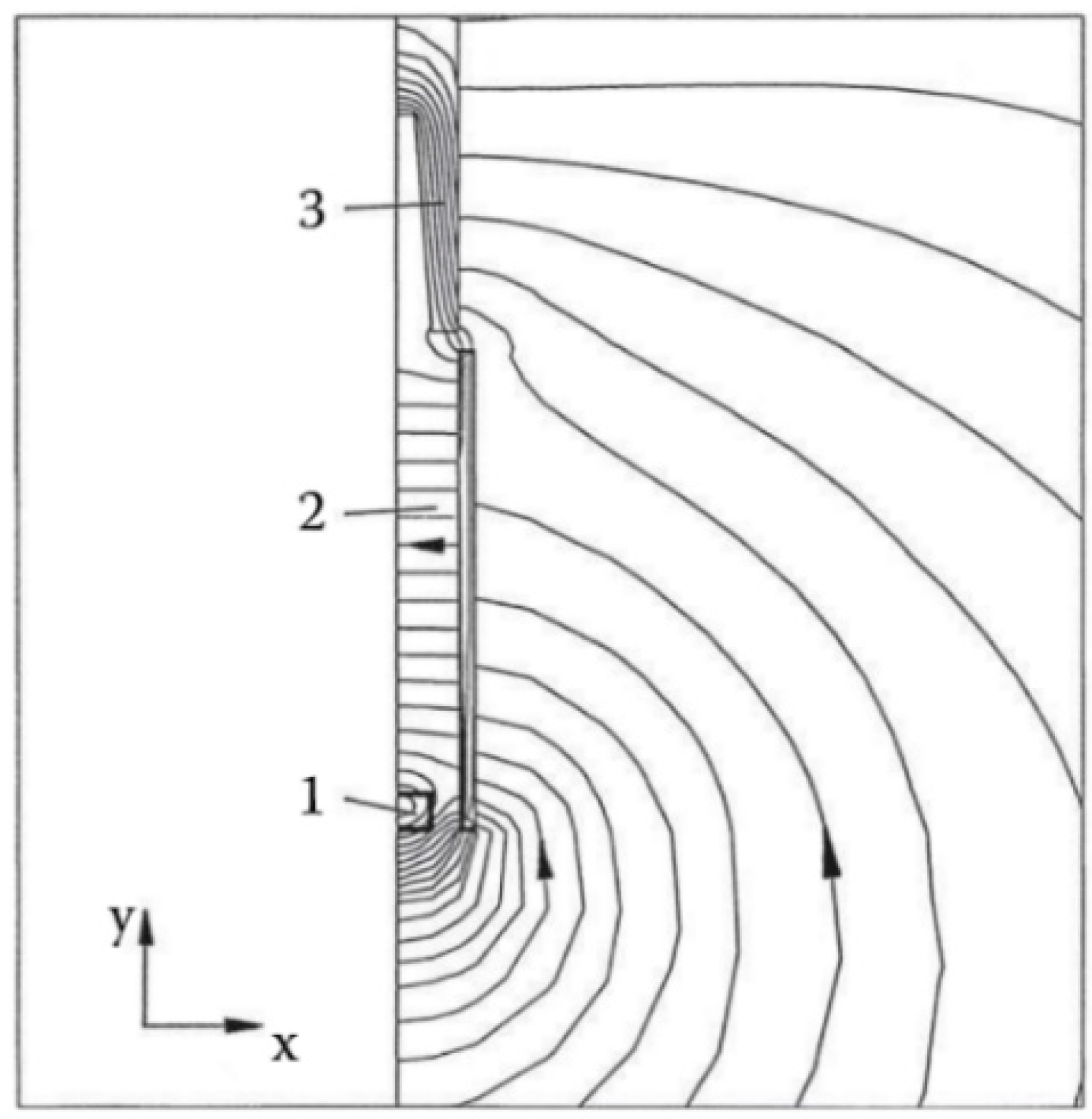
The plates made of a ferromagnetic material, in the structure of the extinguishing chamber, distort the magnetic field generated by the arc, causing the appearance of an electrodynamic force, which attracts the arc towards the plate area.
Figure 3 shows the principle described above.
The magnetic flux density and electrodynamic force vary, depending on the position of the arc, in relation to the plates.
Figure 4 shows an example of the distribution of the magnetic field for different positions of the arc, in relation to the extinguishing chamber metal plates.
Most air circuit breakers use the intrinsic magnetic field created by the chamber’s ferromagnetic plates to move the arc past the contacts towards the extinguishing chamber. This field can be increased by additional ferromagnetic flux concentrators, such as side plates isolated from the arc chute, as shown in
Figure 5 below. The generated lines of magnetic flux tend to flow in areas of minimal magnetic resistance, and the arc is subjected to an electrodynamic force that moves it upwards into the extinguishing chamber.
The contact force (
Fc) necessary to counteract the blow-off force is proportional to the square of the peak current (
I):
where
K2 is coefficient that contains the geometry and also material properties.
Equation (2) below presents the dependency for blow-out force (
Fw):
where
,
Vc is the voltage measured across the contacts.
Hence, great forces are needed to overcome the static and attraction forces from the point contact. In order to limit the complexity of contact layout it is viable to employ the electrodynamic forces. This is necessary, in order to limit the short-circuit current in a brief amount of time. Here, an approved method is to use the magnetic repulsion of two anti-parallel and closely spaced current paths (
Figure 6). This force can be considerably increased by concentrating the self-field of the current path to the moving contact part where the force is needed [
2].
The arc-switching magnetic extinguishing chamber is used, in principle, for switching off all magnitudes of currents and powers. The effect of cooling, dividing, and stretching of the arc on the internal resistance of the arc column is used here. In the magnetic blow-out mechanism, the electric arc between the switch contacts is being pushed by the forces of electromagnetic induction into the extinguishing chamber [
2]. The greatest electrical resistance of the arc occurs in the area near the electrode; therefore, such a division significantly increases the electrical resistance of the arc column. The arc chamber interrupts an electric arc, producing an arc voltage instead of a supply voltage. This voltage can be defined as the smallest voltage that is necessary to maintain the arc. The arc voltage can be increased by cooling the arc plasma. After reducing the temperature of the arc plasma and movement of the particles, an additional voltage gradient is needed to maintain the arc. It is possible to increase the arc voltage while increasing the arc path. As soon as the arc path length is increased, the resistance will also increase the arc voltage that is used across the current path. In a single-point contact system, AgCu material is often used, mainly for the fixed contact, as well as copper (it can be silver-plated, which reduces the flash-on resistance value and, thus, reduces the transition resistance, which should not exceed 1 mΩ) [
2].
Figure 7 shows a system where an electric arc burns between a fixed and moving contact. The movable part of the contact system is, thus, relieved of the stresses of the arc, and the electric arc can be better adapted to the shape of the stack of deionization plates. It is worth noting that this is additional time that can be source of delays. There are also solutions where the fixed guide is not connected to the movable contact, but this connection must be made and held with an additional arc.
4. Simulation Part
In order to verify the above-mentioned theoretical assumptions and determine the return of the acting electrodynamic force, a very detailed 3D model of the ABB overcurrent circuit breaker—S201 C32 was made. Using the software “SpaceClaim Geometry”, all the individual structural elements of the MCB were modeled.
The drawn elements of the overcurrent switch were made with the maximum possible precision, while maintaining their dimensions, shape, and position, in relation to each other. The main parts of the circuit breaker drafted structure are:
Short-circuit release coil combined with the fixed contact of the circuit-breaker;
Moving contact;
Thermobimetal combined with the “arc runner”—the element along which the electric arc is led to the extinguishing chamber;
Arc chamber;
Upper and lower terminal of the switch.
The modeled elements of the current path are shown in
Figure 8 below, which shows the main elements of the overcurrent circuit breaker.
After modeling all the structure elements of the circuit breaker, it was possible to make a 3D assembly for the entire device (
Figure 9 below).
The 3D model of the circuit breaker was loaded into the ANSYS Workbench environment. Numerical analysis for the prepared model was performed using the Maxwell 3D calculation module. After generating the calculation region for numerical simulation, individual parts of the model were assigned material properties from the material library. Then, a current excitation was applied, simulating the flow of a short-circuit current of 6 kA through the analyzed current circuit.
The preliminary mesh for the analysis was defined, where the initial value of the number of elements was set to 1,000,000 elements. When generating the mesh, the solver additionally densified the mesh. The final value of the mesh elements was 1,315,154 elements.
The set simulation time was assumed at the level of 200 ms. Additionally, the time steps of the performed calculations were defined for each 1 ms of the specified simulation time. After that, the computational simulation was launched.
It was possible to generate the distribution of the electromagnetic induction line density in the side ferromagnetic plates and plates of the extinguishing chamber at the moment of opening the contacts and appearance of an electric arc, as shown in
Figure 10 below.
The performed calculations also made it possible to analyze the value of the electrodynamic force acting on the electric arc resulting from the refraction of the electromagnetic arc field line in the side plates. The resulting magnetic flux is closed by the side plates and plates of the extinguishing chamber, causing the electric arc to be forced into the extinguishing chamber. The vector of electrodynamic force interaction on the arc, at the moment of opening the circuit breaker contacts, is shown in
Figure 11 below.
The influence of the electrodynamic force pushes the electric arc formed between the side ferromagnetic plates of the switch, moving it upwards into the extinguishing chamber. The resulting electromagnetic flux from the electric arc is closed in the plates of the extinguishing chamber. Depending on the position of the electric arc, in relation to the plates, the value of the electrodynamic force pushing the arc between the special cuts in the plates of the extinguishing chamber increases. This is due to the thickening of the electromagnetic induction lines in the triangular slots of the plates. In order to analyze this phenomenon in detail, additional induction value distributions were generated, with the resultant electrodynamic force vectors marked for several positions of the electric arc, in relation to the gap of the extinguishing chamber plate (
Figure 12 below).
The simulation calculations of the analyzed electric arc motion were fully consistent with the theoretical assumptions presented by P. Slade for various arc positions in the plate of the extinguishing chamber, presented and described at the beginning of this chapter.
5. Results Validation
The computational simulation, performed in this way, was the basis for conducting the experimental validation of determining the electric arc displacement path inside the extinguishing chamber and between its plates, including the impact of electrodynamic forces on the arc.
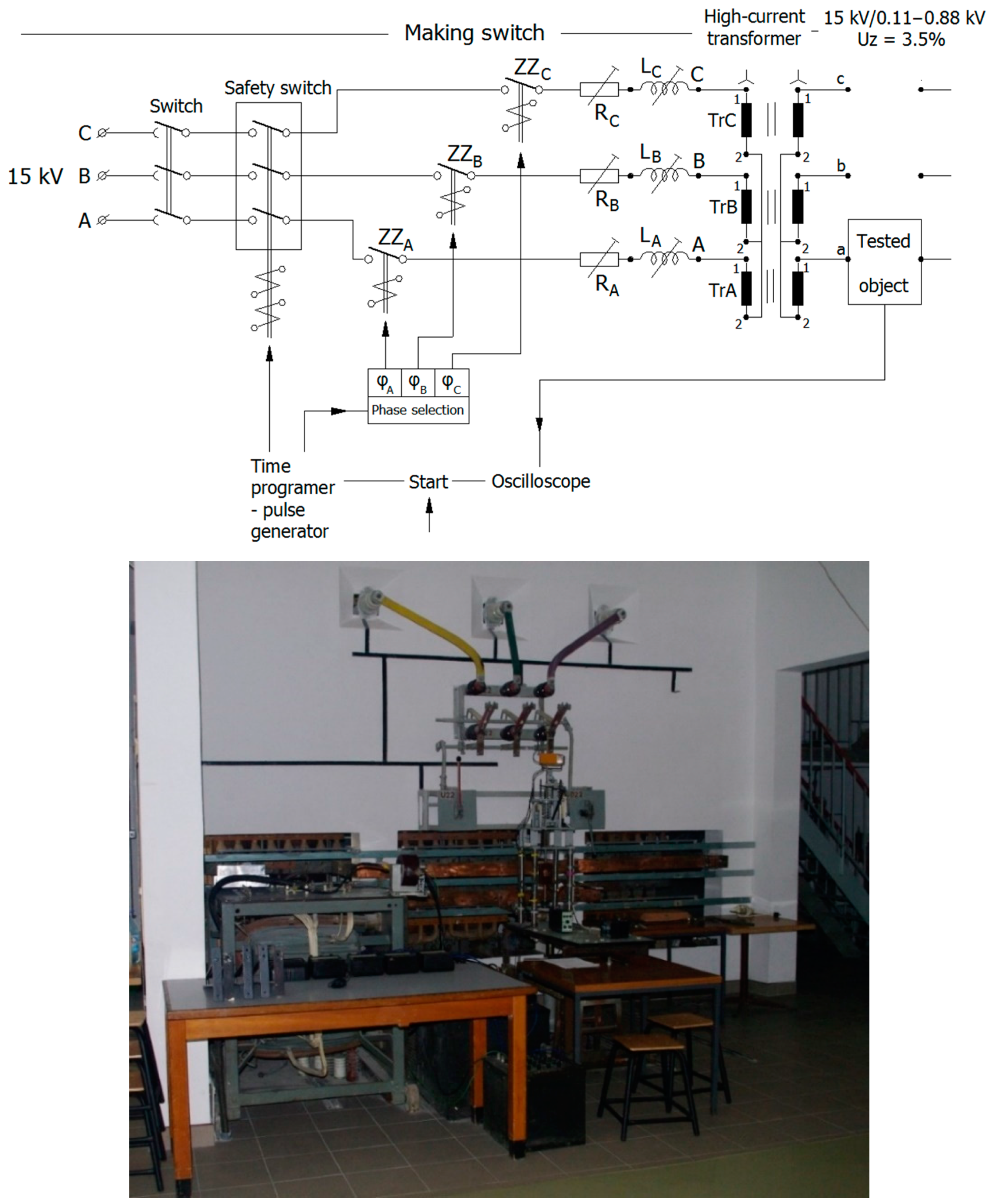
In order to perform the experimental tests, the High-Current Laboratory of the Warsaw University of Technology was used. A diagram of the short-circuit system in the High-Current Laboratory is shown below in
Figure 13 below.
In order to obtain visible paths of the electric arc motion on the plates of the extinguishing chamber, eight short-circuit tests were performed on eight samples of overcurrent circuit breakers with the C characteristic and 32 A rated current (
Figure 14 below).
The tests were performed on one of the short-circuit system lines, as presented in the diagram above. The waveforms obtained from the experimental tests for short-circuit currents of 6 kA for individual tests are presented below (
Figure 15).
The short-circuit tests performed made it possible to obtain and visualize the paths of the electric arc moving along the ferromagnetic plates inside the tested extinguishing chambers. The circuit breakers, after short-circuit tests, had their rivets removed and were dismantled. The extinguishing chambers of the switches were pulled out, unpackaged, and photographed. The photos taken of the plates from the extinguishing chamber were collected and presented below in
Figure 16.
The figures above show the path of the electric arc pushed through the side ferromagnetic plates into the extinguishing chamber. The presented plates of extinguishing chamber show that, through the use of special triangular notches, the electric arc is received from the side plates through the generated electrodynamic forces and directed centrally to the center of the notches in the plates of the extinguishing chamber. The electric arc, after falling into the center of each of the plates, is divided into smaller arcs—their number depends on the number of plates used in the structure of the extinguishing chamber. As the electric arc splits, electrodynamic forces push the arc towards the upper left of each plate. This is precisely represented by the traces on the chamber plates, resulting from the movement of the electric arc on each of them.
The correlation between the oscillograms and plate photographs are depicted in
Table 1 below.
The waveforms of current and voltage are presented in
Figure 13. The results of switching off times and values of switched off currents are presented in
Table 2 below.
The investigated effect was demonstrated on the basis of a single-phase overcurrent circuit breaker B16. The tests were executed in accordance with the subject standard PN-IEC 60898. A switching test was conducted in the scope of the tests. The test site was the Short-Circuit Laboratory of the Institute of Electrical Power Engineering, Warsaw University of Technology. The
Figure 17 below shows a reference short-circuit current waveform with an RMS value of 6400 A.
6. Summary and Conclusions
The short-circuit tests performed confirmed the theoretical assumptions included in the literature. Additionally, the simulation results are consistent with the results obtained from the performed experimental tests. The performed computational simulations confirmed that performing numerical analyzes on accurate 3D construction models can be a significant facilitation during the construction and prototyping of extinguishing chambers. Thanks to this type of analysis, designers of electrical apparatus are able to create devices that are more refined at the design stage. By making appropriate design changes, such as refining the shape of the cutouts in the plates of the extinguishing chamber, it is possible to increase the electrodynamic force acting on the arc falling into the chamber and by appropriately stretching it inside the chamber—e.g., DC current extinguishing chambers in modular circuit breakers. During this work, the execution of the following objectives was achieved:
Analysis of physical phenomena related to the flow of short-circuit current;
Building a 3D model of a low-voltage modular apparatus, which can be used for further work in the field of switching power off. Especially now, where NEMA has issued a directive in which modular apparatuses by 2030 will have to, inter alia, communicate with control devices.
Building a model that is useful not only for researchers, but also designers;
The usefulness of the 3D model made in the ANSYS Maxwell environment for the analysis of physical phenomena, during the flow of rated current, but also during the flow of short-circuit current, was confirmed;
The theoretical assumptions and simulation considerations, based on 2D models, regarding the use of the electrodynamic phenomenon with the use of ferromagnetic plates, were confirmed;
It has been shown that the derived model can be useful in the design of low-voltage modular apparatuses.
The use of coupled analyzes in the process of developing the structure of extinguishing chambers and electrical devices allows to significantly reduce the costs associated with prototypes construction or performing expensive research and tests in research laboratories.
Author Contributions
Conceptualization, M.S., S.Ł. and Ł.K.; data curation, M.S., S.Ł. and Ł.K.; formal analysis, M.S., S.Ł. and Ł.K.; investigation, M.S., S.Ł. and Ł.K.; methodology, M.S., S.Ł. and Ł.K.; project administration, M.S., S.Ł. and Ł.K.; resources, M.S., S.Ł. and Ł.K.; supervision, M.S., S.Ł. and Ł.K.; validation, M.S., S.Ł. and Ł.K.; visualization, M.S., S.Ł. and Ł.K.; writing—original draft preparation, M.S., S.Ł. and Ł.K.; writing—review and editing, M.S., S.Ł. and Ł.K. All authors have read and agreed to the published version of the manuscript.
Funding
This research received no external funding.
Institutional Review Board Statement
Not applicable.
Informed Consent Statement
Not applicable.
Data Availability Statement
Not applicable.
Acknowledgments
The English proofreading of the text was done by Iwona Elżbieta Kolimas and Eric Maclean.
Conflicts of Interest
The authors declare no conflict of interest.
References
- Wang, L.; Liu, H.; Zheng, W.; Guan, R.; Ge, C.; Chen, L.; Jia, S. Numerical Simulation of Impact Effect of Internal Gas Pressure on Chamber Housing in Low-Voltage Circuit Breaker. IEEE Trans. Compon. Packag. Manuf. Technol. 2014, 4, 632–640. [Google Scholar] [CrossRef]
- Slade, P.G. Electrical Contacts; CRC Press: Boca Raton, FL, USA, 16 April 2017. [Google Scholar]
- Lindmayer, M. The influence of Contact Materials and Chamber Wall Material on the Migration and the Splitting of the Arc in Extrinction Chamber. IEEE Trans. Parts Hybrids Packag. 1973, 9, 45–49. [Google Scholar] [CrossRef]
- Degui, C.; Ruicheng, D.; Jingshu, Z.; Weixiong, T. Dynamic Simulation of Operating Mechanism for Molded Case Circuit Breaker. In Proceedings of the 53rd IEEE Holm Conference on Electrical Contacts, Pittsburgh, PA, USA, 16–19 September 2007. [Google Scholar]
- Ye, X.; Dhotre, M.T.; Mantilla, J.D.; Kotilainen, S. CFD Analysis of the Thermal Interruption Process of Gases with Low Environmental Impact in High V oltage Circuit Breakers. In Proceedings of the 2015 Electrical Insulation Conference (EIC), Seattle, WA, USA, 7–10 June 2015. [Google Scholar]
- Bura, V.S.; Diptisikha, R. Effect of different Deion plate surface finishes on arc mobility at higher voltage and fault currents. In Proceedings of the 2018 IEEMA Engineer Infinite Conference, New Delhi, India, 13–14 March 2018. [Google Scholar]
- Dhotre, M.T.; Ye, X.; Seeger, M.; Schwinne, M.; Kotilainen, S. CFD Simulation and Prediction of Breakdown Voltage in High Voltage Circuit Breakers. In Proceedings of the 2017 Electrical Insulation Conference (EIC), Baltimore, MD, USA, 11–14 June 2017. [Google Scholar]
- Qi, B.; Zhao, X.; Zhang, S.; Huang, M.; Li, C. Measurement of the electric field strength in transformer oil under impulse voltage. IEEE Trans. Dielectr. Electr. Insul. 2017, 24, 1256–1262. [Google Scholar] [CrossRef]
- Bura, V.S.; Satbir, S.; Medhora, R.; Legha, A. Effect of Different De-ion Plate Surface Finishes on Arc Mobility. In Proceedings of the 2008 JIC on Power System Technology and IEEE Power India Conference, New Delhi, India, 12–15 October 2008. [Google Scholar]
- Rumpler, C.; Stammberger, H.; Zacharias, A. Low-voltage arc simulation with out-gassing polymers. In Proceedings of the 2011 IEEE 57th Holm Conference on Electrical Contacts (Holm), Minneapolis, MN, USA, 11–14 September 2011; pp. 1–8. [Google Scholar]
- Ryzhov, V.V.; Molokanov, O.N.; Dergachev, P.A.; Vedechenkov, N.A.; Kurbatova, E.P.; Kurbatov, P.A. Simulation of the Low–Voltage DC Arc. In Proceedings of the Intenational Youth Conference on Radio Electronics, Electrical and Power Engineering (REEPE), Moscow, Russia, 14–15 March 2019. [Google Scholar]
- Galvan, E.; Rodrigues, J.J. Study of the influence of permanent magnets in the interruption process of the electrical arc in MCB. In Proceedings of the 2017 IEEE Holm Conference Electrical Contacts, Denver, CO, USA, 10–13 September 2017. [Google Scholar]
- Geetha, N.D.; Rasilo, P.; Arkkio, A. Sensitivity Analysis of Inverse Thermal Modeling to Determine Power Losses in Electrical Machines. IEEE Trans. Magn. 2018, 54, 1–5. [Google Scholar]
- Li, J.; Cao, Y.; Yan, M.; Liu, S.; Du, Z.; Feng, Y. Research on the Effect of Magnetic Field on Micro-Characteristics of Vacumm Arc During Arc Formation Process. In Proceedings of the 28th International Symposium on Discharges and Electrical Insulation in Vacuum (ISDEIV), Greifswald, Germany, 23–28 September 2018. [Google Scholar]
- Tarnowski, P.; Ostapski, W. Pulse powered turbine engine concept—Numerical analysis of influence of different valve timing concepts on thermodynamic performance. Bull. Pol. Acad. Sci. Tech. Sci. 2018, 66, 373–382. [Google Scholar]
- Nagarajan, V.S.; Kamaraj, V.; Sivaramakrishnan, S. Geometrical sensitivity analysis based on design optimization and multiphysics analysis of PM assisted synchronous reluctance motor. Bull. Pol. Acad. Sci. Tech. Sci. 2019, 67, 155–163. [Google Scholar]
- Bini, R.; Basse, N.T.; Seeger, M. Arc-induced Turbulent Mixing in a Circuit Breaker Model. J. Phys. D Appl. Phys. 2011, 44, 25203. [Google Scholar] [CrossRef] [Green Version]
- Holm, R. Electric Contacts—Theory and Application; Springer: New York, NY, USA, 2013. [Google Scholar]
- Basse, N.P.T.; Bini, R.; Seeger, M. Measured turbulent mixing in a small-scale circuit breaker model. Appl. Opt. 2009, 48, 6381–6391. [Google Scholar] [CrossRef] [PubMed]
- Incropera, F.P.; DeWitt, D.P.; Bergman, T.L.; Lavine, A.S. Introduction to Heat Transfer, 5th ed.; Wiley: Hoboken, NJ, USA, 2006. [Google Scholar]
- Muller, P.T. Macroscopic Electro Thermal Simulation of Contact Resis—Tances. Bachelor’s Thesis, RWTH Aachen University, Aachen, Germany, 2016. [Google Scholar]
- Biao, W.; Yanyan, L.; Xiaojun, Z. Study on detection technology of the contact pressure on the electrical contacts of relays. In Proceedings of the 26th International Conference on Electrical Contacts (ICEC 2012), Beijing, China, 14–17 May 2012; pp. 161–164. [Google Scholar]
- Sun, X.; Su, B.; Chen, L.; Yang, Z.; Li, K. Design and analysis of interior composite-rotor bearingless permanent magnet synchronous motors with two layer permanent magnets. Bull. Pol. Acad. Sci. Tech. Sci. 2017, 65, 833–843. [Google Scholar] [CrossRef]
- Kriegelet, M.; Zhu, X.; Digard, H.; Feitoza, S.; Glinkowki, M.; Grund, A.; Kim, H.K.; Lopez Roldan, J.; Robin-Jouan, P.; van der Sluis, L.; et al. Simulations and Calculations as verfication tools for design and performance of high voltage equipment. In Proceedings of the Cigre Conference 2008, Paris, France, 25–28 August 2008. paper A3-210. [Google Scholar]
- Kumar, P.; Kale, A. 3-Dimensional CFD simulation of an internal arc in various compartments of LV/MV Switchgear. In Proceedings of the ANSYS Convergence Conference, Pune, India, 23 August 2016. [Google Scholar]
- Hartland, D.J. Electric contact systems—Passing power to the trains. In Proceedings of the IET Professional Development Course on Electric Traction Systems, London, UK, 6–9 June 2011; pp. 25–37. [Google Scholar]
- Chen, G.; Lan, L.; Wen, Z.P.X.; Wang, Y.; Wu, Y. Electrical erosion test and condition assessment of SF6 CB contact sets. IET Gener. Transm. Distrib. 2017, 11, 1901–1909. [Google Scholar] [CrossRef]
- Mantilla, J.D.; Gariboldi, N.; Grob, S.; Claessens, M. Investigation of the insulation performance of a new gas mixture with extremely low GWP. In Proceedings of the Electrical Insulation Conference, Philadelphia, PA, USA, 8–11 June 2014. [Google Scholar]
- Iordanidis, A.A.; Franck, C.M. Self-consistent radiation-based simulation of electric arcs: II. Application to gas circuit breakers. J. Phys. D Appl. Phys. 2008, 41, 135206. [Google Scholar] [CrossRef]
- Ye, X.; Dhotre, M.T. CFD Simulation of Transonic Flow in High-Voltage Circuit Breaker. Int. J. Chem. Eng. 2012, 2012, 609486. [Google Scholar] [CrossRef] [Green Version]
- Kim, H.; Chong, I.; Lee, S. Analysis of SLF Interruption Performance of Self-Blast Circuit Breaker by Means of CFD Calculation. J. Electr. Eng. Technol. 2014, 9, 254–258. [Google Scholar] [CrossRef] [Green Version]
- Lindmayer, M.; Stammberger, H. Application of numerical field simulations for low-voltage circuit breakers. IEEE Trans. Compon. Packag. Manuf. Technol. Part A 1995, 18, 708–717. [Google Scholar] [CrossRef]
- Frei, P.U.; Weichert, H.O. Advanced Thermal Simulation of a Circuit Breaker. In Proceedings of the 50th IEEE Holm Conference on Electrical Contacts and the 22nd International Conference on Electrical Contacts, Seattle, WA, USA, 23–23 September 2004. [Google Scholar]
- Ito, S.; Takato, Y.; Kawase, Y.; Ota, T. Numerical analysis of electromagnetic forces in low voltage AC circuit breakers using 3-D finite element method taking into account eddy currents. IEEE Trans. Magn. 1998, 34, 2597–2600. [Google Scholar] [CrossRef]
| Publisher’s Note: MDPI stays neutral with regard to jurisdictional claims in published maps and institutional affiliations. |
© 2022 by the authors. Licensee MDPI, Basel, Switzerland. This article is an open access article distributed under the terms and conditions of the Creative Commons Attribution (CC BY) license (https://creativecommons.org/licenses/by/4.0/).


