Abstract
With the rapid growth of the oil and gas storage, transportation, and pipeline industries, it is necessary to improve the construction process of oil and gas pipelines. By combining the technical advantages of horizontal directional drilling and pipe jacking construction, the direct pipe laying method is suitable for pipeline crossing in different strata in the oil and gas, water conservancy and hydropower, and municipal industries due to its advantages of less construction land, high speed, and reversibility. Using the rapid jacking and laying of pipelines crossing Nanjuma River in the ‘Jingshihan’ gas pipeline double line project as a case study, this paper investigates the application status of the direct pipe laying method, summarizes the project, and introduces the construction of the working well, equipment selection, guiding control technology, supporting equipment installation, and drag reduction measures, as well as analyzes the influencing factors of thrust force and trajectory deviation combined with formation information.
1. Introduction
Oil and gas pipelines represent one of the main ways to transport oil and gas resources around the world. In order to further improve the safety of oil and gas transportation, it is imperative to optimize and upgrade the construction of oil and gas transportation pipelines. The stable supply of oil and gas is one of the key factors to ensure the steady development of the social economy, for which the construction of oil and gas transportation pipelines is extremely important [1]. The construction of pipelines is a highly systematic and professionally complex project. With the growth of the oil and gas pipeline industry, a series of challenges in the construction of actual storage and transportation pipelines have attracted the attention of the academic community and have gradually become an important research direction in this field [2].
During the buried installation of oil and gas pipelines, they cross roads, railways, waters, mountains, and other aboveground and underground structures [3]. To reduce the impact on existing buildings and environment, trenchless construction crossing has widely been used in long-distance pipeline crossing projects around the world. At present, the trenchless construction of oil and gas pipelines mainly includes horizontal directional drilling, pipe jacking, shield tunnel, and drill-blast tunnel methods [4].
Horizontal directional drilling construction has a great influence on the crossing distance, with long period of repeated hole expansion and serious mud pollution [5]. It has low adaptability to complex hard rock strata, and the use of counterweights and floating leads to a short life cycle of the pipeline and difficult maintenance in the later period. The pipe jacking method requires an excavation of the working well, the preliminary work is more complex, and the construction efficiency is significantly reduced when the measured construction distance is more than 800 m [6]. There are still problems such as increasing friction and a high risk of the pipeline becoming stuck when long distance passes are crossed through complex strata. Although shield construction has strong adaptability, its equipment structure is complex, the manufacturing, installation, and commissioning cycle is the longest, and the cost is high [7].
Considering the advantages and disadvantages of the several types of trenchless construction techniques described above for oil and gas pipelines, the rapid jacking and pipeline laying method came into being. This technology has fewer requirements for the construction site, can achieve drilling and pipe laying in one step, and has the characteristics of a short construction period, moderate cost, and strong applicability [8].
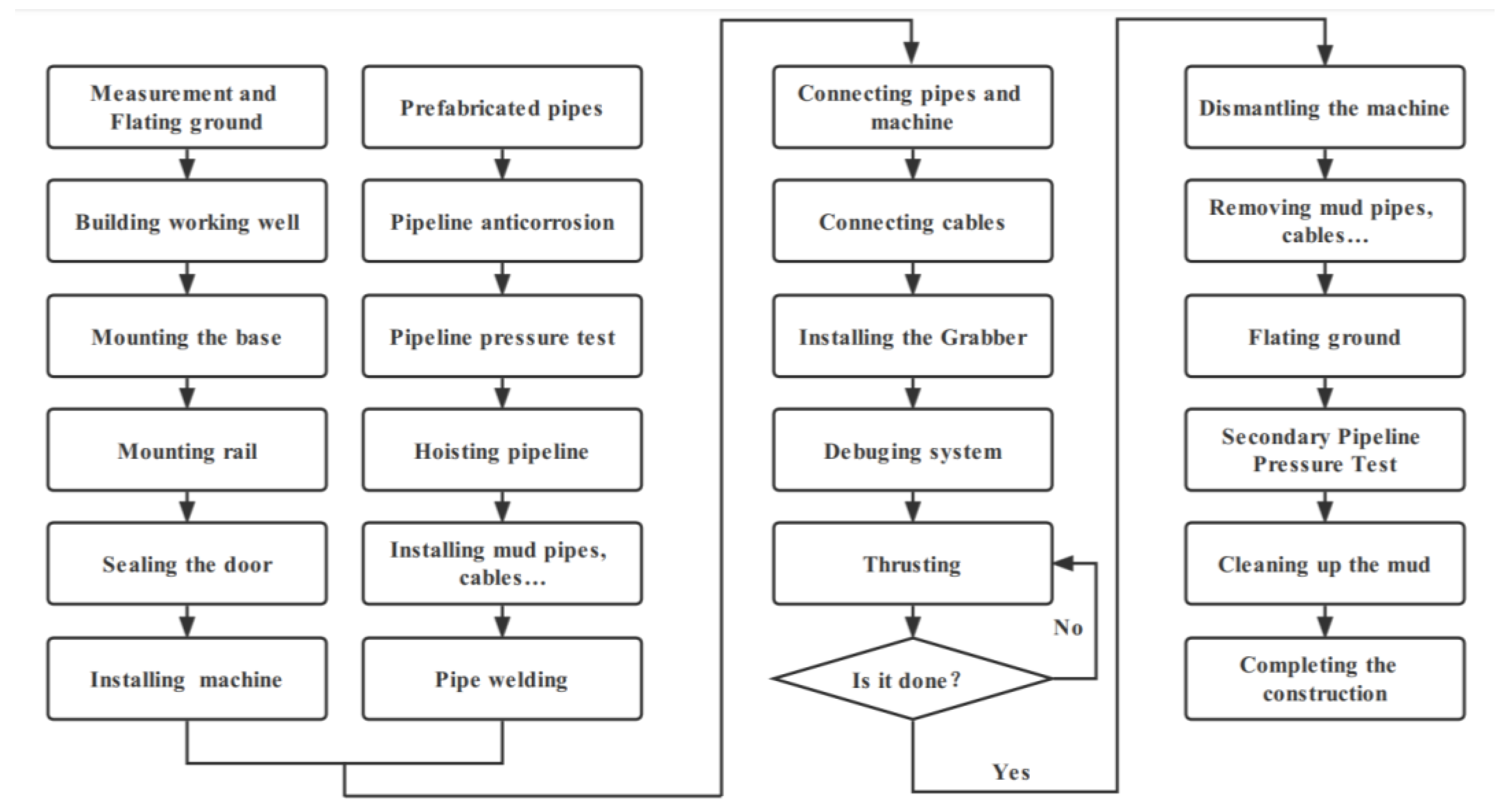
The rapid jacking and pipeline laying method combines pipe jacking and directional drilling technology. The principle is to use a boring machine for tunnel excavation at the front of the pipelines, connect the pipeline to be laid with the direct pipe laying machine, clamp the pipeline with the clamping device, and use the friction to thrust the pipelines and equipment forward under the action of the thrusting machine. The method combines the advantages of pipe jacking and horizontal directional drilling to realize the simultaneous progress of prefabricated pipelines and tunnel excavation, so that the prefabricated pipelines can be laid in one push. With its advantages of a small construction area, high speed, and retractability, it is suitable for pipeline crossing in sand, silt, clay, pebble, gravel, rock, and other strata in various programs such as oil and gas, water conservancy, and hydropower engineering, as well as municipalities, with a diameter range of 800–1500 mm [9,10]. The process of the direct laying method is outlined in Figure 1.
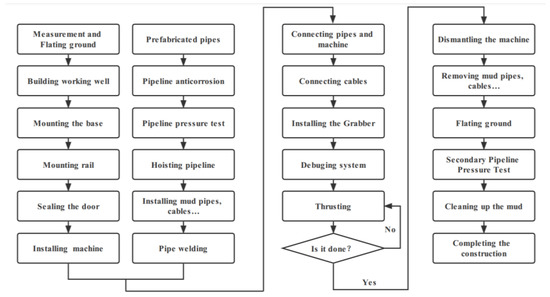
Figure 1.
Flowchart of the rapid jacking and pipeline laying method.
The rapid jacking and pipeline laying method and its equipment have been used in Germany, the Netherlands, Italy, the UK, France, Canada, and other countries since it originated, and China introduced support for the rapid jacking and pipeline laying method in 2013. Table 1 lists some of the projects that used the rapid jacking and pipeline laying method. According to records, the longest pipeline length constructed using the DP method was 1400 m (4593 ft). This was a gas pipeline project in the Netherlands called the Pipeline Ommen–Esveld, crossing in Lochem (constructed in 2011), with a pipe diameter of 1219.2 mm. In September 2016, this method was applied for the first time in China and tested and verified in the project crossing the Chuanshan River in the reroute project of the Zhenjiang University Park of the west–east gas pipeline, with a crossing horizontal distance of 346 m [11]. In January 2017, this construction method was promoted and applied in Wuding River in the Shaanxi–Beijing Fourth Line Pipeline Project [12].

Table 1.
Construction cases of rapid jacking and pipelines laying method.
2. Project Overview
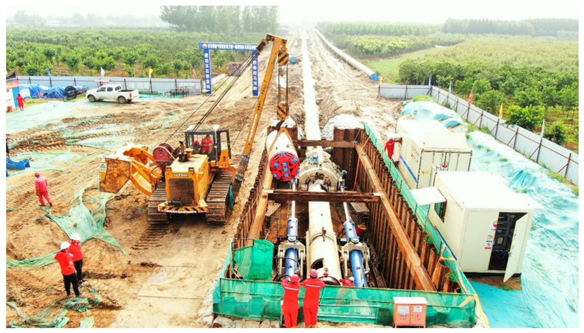
The double-track project of the ‘Jingshihan’ gas pipeline is divided into two sections. This paper deals with the first section (Zhuozhou–Dingxing section). The whole length of the line is about 47.2 km, the diameter is D1219 mm, and the design pressure is 10 MPa. According to the overall trend of the line, Nanhou Village, Dingxing County, Baoding City, Hebei Province passes through the ‘Nanjuma’ River, using the rapid jacking and pipeline laying method. The pressure at the crossing point is 10 MPa, the transportation temperature is 0–20 °C, and the regional grade is two. The steel pipe in the crossing section is a D1219 × 27.5 mm L555M longitudinal submerged arc-welded steel pipe, and the 3LPE strengthening outer coating is used for anticorrosion at room temperature. The grade of the crossing project is large. Considering the factors such as the buried depth of the curve, the geological conditions at the crossing point, the scour depth, and the position of the exploration line, the entry angle was set to 5°, and the excavation angle was set to 6°. The horizontal length of the crossing is 560 m. Considering the stress characteristics of pipelines and the capacity of the rapid laying and jacking machine, the curvature radius of the pipe crossing section is 1500 * D (D is the outer diameter of the pipe crossing section: 1219 mm), which is 1828.5 m. The construction site plan is shown in Figure 2.

Figure 2.
Figure of overall layout of construction site.
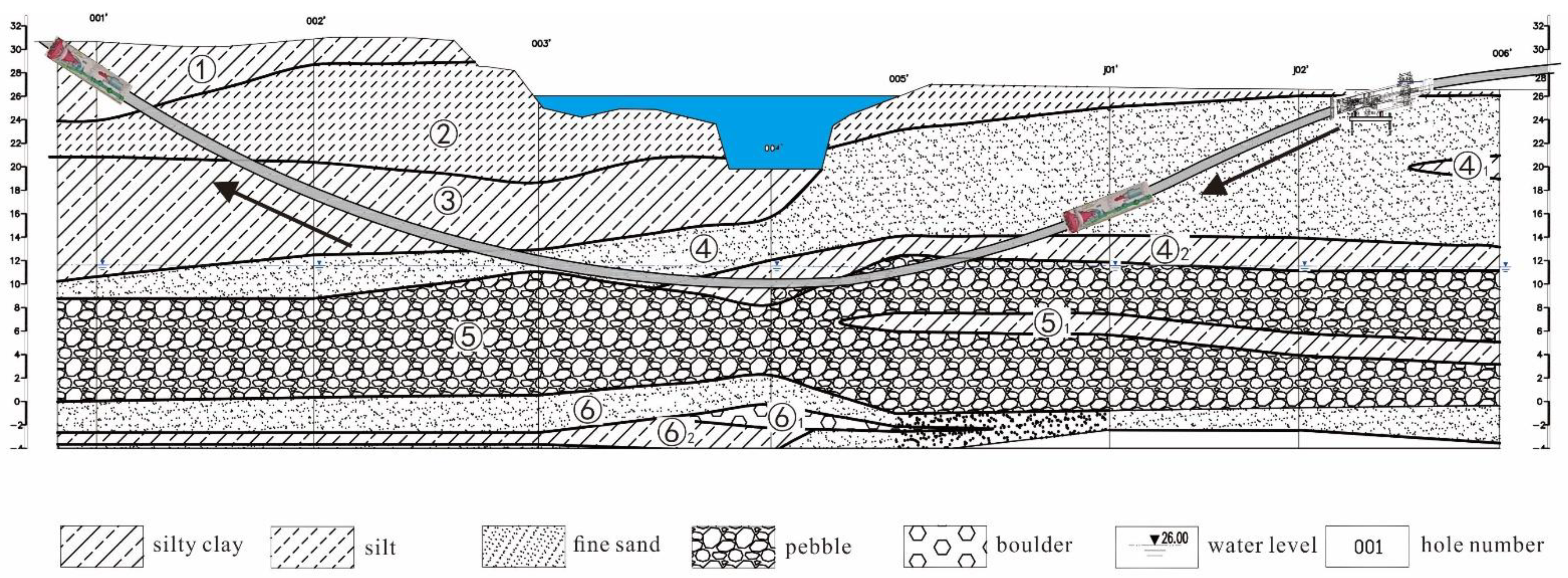
The soils were classified according to Chinese standard of GB 50568-2010 [13]. The strata were mainly silt, fine sand, pebble layer, and silty clay. The subsurface conditions along the pipeline are shown in Figure 3, and the soil distribution and characteristics of each formation are summarized in Table 2 and Table 3.

Figure 3.
Geological profile of this project.
Table 2.
Summary of soil properties.
Table 3.
Summary of average grain composition of pebble layer and sand layer.
3. The Key Points and Challenges of This Project
According to the design drawings, geological data, construction specifications, and owners’ regulations and requirements, through careful reading and analysis of construction data, and considering the characteristics, functions, and natural conditions of the project, the key points and challenges of this project are as follows:
(1) The friction resistance of long-distance pipelines is large, there is a risk of the pipe becoming stuck [6], and the requirement for lubrication grouting is high.
The crossing length of the pipeline in this project is long. Since the pipe thrust machine provides 500 t of thrust, it was calculated according to the grouting friction reduction coefficient that the requirements can be met only when lubrication slurry is injected abundantly and the lubrication effect is great. Because the oil and gas pipeline cannot be drilled on the pipe wall for annular grouting, it can only be grouted slowly through the front end of the boring machine. Therefore, this project has strict requirements for the formulation of lubricating mud and mud pressure.
(2) Through the cobble layer, the excavation face is easy to collapse, large pebbles are difficult to break, and the mud carrying debris poses a challenge.
The project has a pebble layer section of about 70 m, with a pebble particle size of 3 to 6 cm and a maximum particle size of 8 cm; the boring machine through this section of the excavation face is unstable and can easily collapse, and the mud lubrication effect is poor, which leads to difficulties, such as mud pipe accidents.
(3) It is difficult to control the trajectory when crossing complex strata.
The trajectory of this project is a vertical curve in the process of crossing, and it is complex to cross the stratum. Deviation in the vertical direction deviation of the boring machine can easily occur at the stratum boundary. In particular, when crossing the pebble layer, the attitude control of the boring machine is difficult, and the trajectory can easily deviate, making it difficult to correct the deviation.
4. Key Technology of the Construction
4.1. Driving Shaft Construction
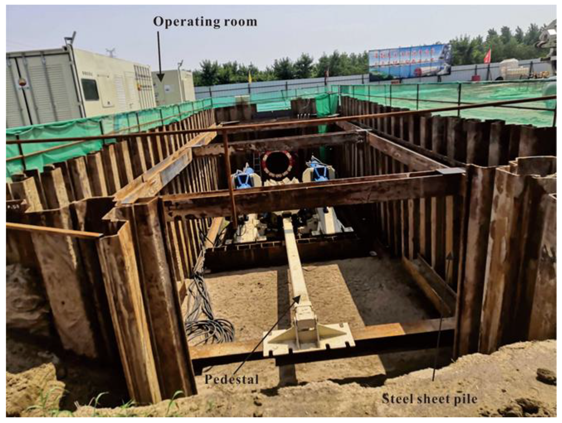
Since the rapid jacking and pipeline laying method has low requirements in terms of the driving shaft structure, considering the factors such as construction period and cost, the steel sheet pile supporting structure featuring fast construction, low cost, and recyclability was selected. The foundation pit of the shaft was supported by an SP-U400 × 170 × 15.5 hot-rolled U-shaped steel sheet pile with a length of 9 m. The purlin and support were hot-rolled Q235B grade HW400 × 400 × 13 × 21 mm steel. The pipeline crossing space was reserved at the end. The back end of the foundation pit was sloped from 5° at the bottom of the pit, leaving enough suitable slope for the subsequent cut back. The length of the foundation pit was 22 m, the width was 6.8 m, the depth of the soil entry point of the pipeline axis was 3.0 m, and the installation space of the reserved hole seal and ground anchor was 1.5 m. The excavation depth of the initial foundation pit was 4.8 m, the pouring of concrete occurred at 30 cm, and the bottom plate was 4.5 m deep with respect to the original ground. The first purlin and support of the foundation pit went down 1.0 m from the top of the steel sheet pile, and three supports were arranged at the front end of 12 m with a spacing of 3.5 m. There was no support at the back end of the first layer. Affected by the limit of the pipe clamp stroke, the second purlin of the foundation pit was 3.3 m from the top of the steel sheet pile, and one pipe was set at the end of the foundation pit, with a spacing of 5 m.
After the overall structure was completed, H-shaped steel was installed at the bottom through the anchor, which was convenient for the subsequent installation of the pedestal of the thrust machine, as shown in Figure 4.
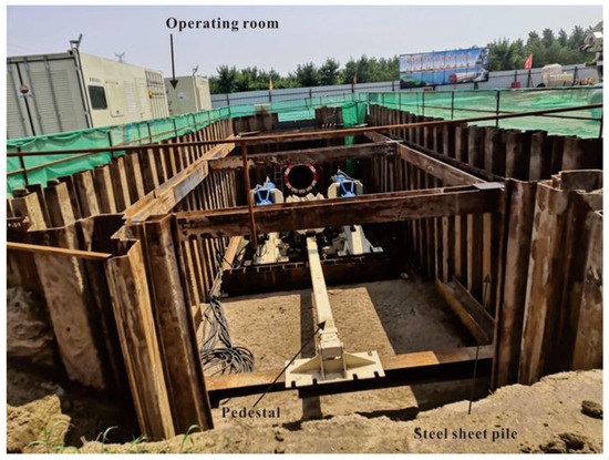
Figure 4.
Driving shaft structure and installation diagram.
4.2. Equipment Selection
4.2.1. Selection of Boring Machine
The boring machine is used for tunnel construction, and its principle is similar to the slurry balance pipe jacking equipment. On the basis of pipe jacking construction, the dynamic configuration, curve guidance, lubrication system, and slurry transportation were optimized. According to the pipe jacking construction parameters, combined with the characteristics of pipeline construction, the overcut diameter [14] should be larger than the pipeline diameter. According to the actual situation, as gas pipeline with a diameter of 1219 mm, mainly passing through the fine sand layer, was selected in this project. The length of the main engine was about 14 m, the weight of the whole machine was about 200 t, and the excavation diameter was 1330 mm. Considering the risk of the pipe becoming stuck due to extreme geological conditions, the maximum thrust force of the equipment was 5000 kN. The rapid laying and jacking machine was composed of a power system, thrust section, and tail shield system (mud pump), driven by 90 kW hydraulic pressure. The head of the boring machine was equipped with a compound cutter head, and the head torque reached 120 kN·m. The specific parameters of the equipment are shown in Table 4.
Table 4.
Specifications of the rapid laying and jacking machine.
The tunnel through the complex strata, including silt, fine sand, pebble layer, and silty clay, for this project had a pebble layer section of about 70 m, with a pebble particle size of 3–6 cm and a maximum particle size of 8 cm; according to the characteristics of permeability, particle size distribution, groundwater pressure, technical parameters of the cutter head, and diameter of the pipelines, specific equipment selection and transformation were carried out. In addition, some unpredictable obstacles were expected in the process of pipeline crossing, such as large boulders, reinforced concrete pile foundation [15].
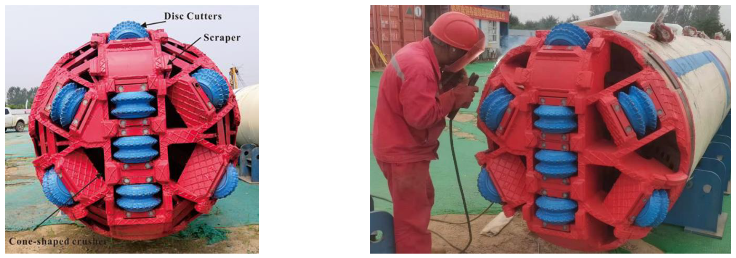
Therefore, the composite cutter head was specially designed for the particularity of the strata. To cut soft soils and break pebble and other unpredictable obstacles, a mixed cutter head with a diameter of 1330 mm (Figure 5) was used, which was installed with disc cutters for rock formations and scraper cutters for soft soil formations. Moreover, a cone-shaped crusher in the excavation chamber, with a function of secondary cutting, reduced the diameter of stones and other obstructions to a conveyable grain size during thrusting of the pipeline.

Figure 5.
Layout form and modification of cutter head of the boring machine.
4.2.2. Selection of Thrust Machine
The thrust machine is a power device that clamps the pipe through a pipe-clamping device and then advances through a cylinder connected to the clamping device under thrust. The inner side of the clamping device is made from special vulcanized rubber, which will not cause damage to the pipeline coating under clamping. During construction, the pipe thrust machine mainly overcomes the resistance of the direct pipe laying machine to the heading face, the friction between the pipe wall and the rock and soil, the viscous force between the pipe and the slurry, and the friction caused by the pipe buckling. At present, there are three specifications of the thrust equipment, with corresponding thrusts of 3000 kN, 5000 kN, and 7500 kN. According to the calculation results of friction, combined with the existing experience with the rapid jacking and pipeline laying method, and consulting the construction data of similar projects abroad, the theoretical maximum thrust of this project was about 3000 kN. Considering that the large slope construction equipment needs a large pullback force when failure occurs, and the thrust machine should have 1.5–2 times the safety factor, this project selected the thrust machine shown in Figure 6, with a maximum thrust of 5000 kN, mainly composed of a pedestal, clamping device, and hydraulic cylinder.
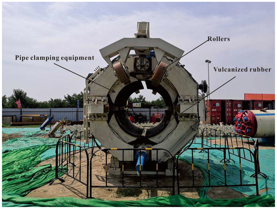
Figure 6.
The thrust machine of the rapid laying and jacking machine.
4.3. Trajectory Control of Boring Machine
The rapid laying and jacking machine features a gyro-guided automatic measurement system. Before starting, the parameters of the designed excavation route are input into the computer in advance, and the measurement is tracked during the propulsion process. The measurement parameters are transmitted to the computer automatically in real time. The actual propulsion route and the design route are compared, and the processing results are fed back to the operating room in an intuitive way. The steering cylinder is controlled by the displayed data, so that the boring machine moves along the axis direction.
- (1)
- The automatic measurement numerical display includes the longitudinal slope, lateral angle, plane deviation, elevation deviation, and incision mileage, to promote the monitoring of numerical changes in construction, with the timely adjustment of various parameters;
- (2)
- When the boring machine starts to advance, the guide cylinder stroke is adjusted to avoid the sinking phenomenon after the header starts to enter the soil;
- (3)
- The angle of the boring machine is checked after every 2 m of propulsion, and the attitude of the machine is adjusted when deviation occurs;
- (4)
- After advancing 20 m, measurements are carried out. The allowable deviation of the pipeline position is ±30 mm, and the direction of the center line should be offset after advancing 50 m. When deviation occurs, it should be corrected in time. When the equipment is advancing, rectification should be carried out slowly, and a large angle (30°) of rectification cannot be carried out at once, so as to prevent subsequent pipeline jamming and deformation.
The horizontal and vertical deviation of the pipeline is shown in Figure 7. Due to the vertical curve of the pipeline crossing in space and various strata, it was difficult to correct the deviation in the vertical direction, which was prone to error. Upon advancing to the position of 160.5 m, the front end of the boring machine entered the pebble layer, and the bearing capacity of the stratum with large porosity was low. The trajectory of the boring machine began to sink in the vertical direction, and it was difficult to correct the deviation. Due to the trajectory deviation, when jacking to the position of 178.5 m, the friction around the pipe reached 5365 kN, and the pipe thrust machine became unable to thrust the whole pipe. By using the cylinder retraction of the pipe thrust machine to provide tension, the pipe was pulled back to the position of 157 m of the boring machine, and then thrust again (Figure 8).
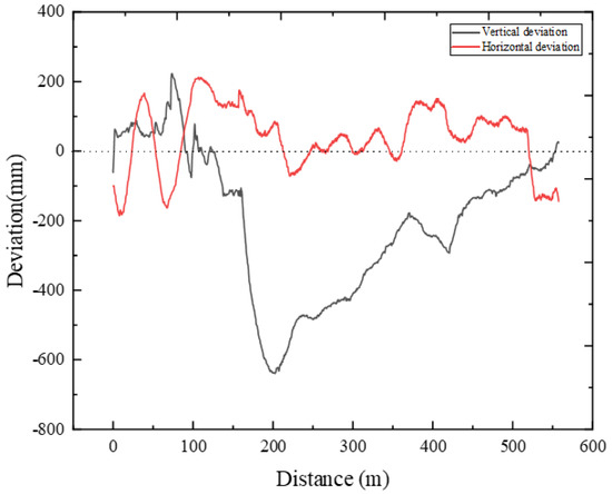
Figure 7.
The deviation of the pipeline.

Figure 8.
The thrust distance over time.
When the boring machine reached 373 m, the water and soil pressure in front of the head was large, and the slurry discharge was large, while the displacement could not be accurately determined. Therefore, formation loss was caused, and the attitude of the boring machine pointed downward again. Upon reaching 420 m, with the decrease in water and soil pressure, the bottom layer became gradually stable, and the propulsion trajectory was gradually corrected. When the boring machine reached the unearthed point, the vertical direction error was 24.0 mm, and the horizontal direction error was 144.0 mm (Figure 7). The feasibility of the guidance system was verified by measuring the trajectory.
4.4. Equipment Installation
4.4.1. Hole Sealing
The hole seal (Figure 9) should be firmly installed at the entry point of the originating well to prevent the leakage of water, sand, and mud in the annular space gap during excavation, so as to ensure that there is enough mud in the annular space gap to support the stability of the hole wall and lubricate the pipeline.
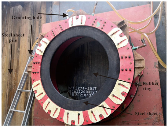
Figure 9.
The hole seal of the rapid jacking and pipeline laying method.
Before installation, the hole seal was first installed on the prefabricated frame of the hole according to the soil entry angle to ensure that the hole was perpendicular to the equipment and to prevent groundwater and sand from pouring into the starting well. A 2.2 m × 2.2 m square frame was welded to the steel plate side according to the soil entry angle. Then, the center coordinates of the soil entry point and the edge position were determined in the steel sheet pile. The prefabricated steel portal was welded to the 20 mm steel plate, and the existing portal sealing ring was installed.
The whole pipeline was thrust by the thrust machine, and the boring machine was slowly thrust into the hole. Thrusting was halted when the cutter head was about to reach the sealing position. The position of the fan seal pressure plate was adjusted so that the diameter of the ring formed by the fan pressure plate was larger than the diameter of the cutter head, thereby ensuring that the cutter head could pass. At the same time, the seal ring was smeared with grease to lubricate the sealing part to prevent the wear and damage of the seal ring. After adjustment, the hydraulic cylinder began thrusting the boring machine forward. The cutter head was slowly thrust into the sealing ring of the hole, and then the cutter head was thrust into the outer plate of the hole. Finally, the outer plate of the hole was removed with a crane, and it was verified whether the rubber seal of the hole was intact.
When all inspections were correct, the operators in the starting foundation pit communicated with the driving driver in the well control room to control the propulsion speed and ensure that the attitude of the boring machine did not change. After everything was confirmed to be normal, the boring machine began to move forward formally.
4.4.2. Pedestal Installation
The ground anchor adopted the combination scheme of a steel sheet pile and H-shaped steel, the frame composed of the thrust machine pedestal (Figure 10) and H-shaped steel was fixed, and the steel sheet pile provided the horizontal and vertical components generated by the thrust machine. The pedestal was divided into two main parts, which were installed and fixed on the ground anchor at the bottom of the driving shaft. Each part of the pedestal could be mounted separately into the driving shaft using a crane.
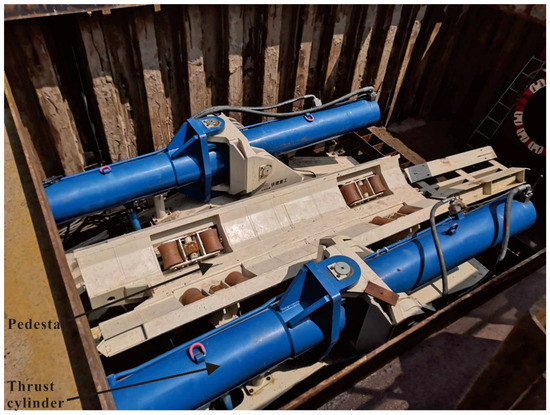
Figure 10.
The pedestal of the thrust machine.
4.4.3. Circulating Mud
The prefabricated length of the ‘Nanjuma’ River pipeline was 590 m, of which the actual length of the rapid jacking and pipeline laying crossing section was 571.64 m. The slope of the entry point of the crossing section was 5°; hence, it was necessary to set up one slurry supply pump and two slurry discharge pumps. The grouting pump was installed on one side of the slurry separation device, and one of the discharge pumps was installed on the tail shield (inside the pipe adapter). Another slurry pump was installed in the middle of the pipeline for mud transportation. The project mud-water separation equipment and pump (Figure 11) were installed at a distance of about 300 m from the starting point of the foundation pit to separate the residue in the circulating mud. The mud circulation equipment layout of the whole pipeline is shown in Figure 12.
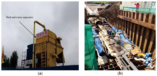
Figure 11.
The project mud–water separation equipment and installed pump: (a) mud–water separation equipment; (b) installed pump.
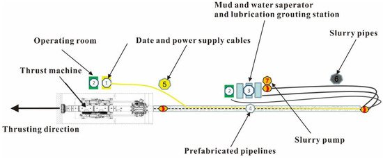
Figure 12.
The mud circulation equipment layout of the whole pipeline.
In order to maintain the stability of the excavation face and carry pebble residue, the viscosity of the circulating mud funnel was controlled at 80 s and the specific gravity was controlled at 1.05–1.2 g/cm3.
The control of the mud circulation pressure was determined by the actual situation of the excavated strata, mainly as a function of groundwater pressure, permeability coefficient, loose situation, and seepage quantity.
Under normal working conditions, the slurry pressure changes the input flow and output flow by setting the slurry pump on the ground and the rotational speed of the slurry discharge pump in the pipeline, so as to control the slurry pressure in the cutter head cabin and keep the slurry pressure in balance with the water and soil pressure on the excavation surface. In general, the mud pressure control value is
where P is the boring machine mud control pressure, and P0 is the combined value of water and soil pressure at the site of the boring machine.
At the same time, in the tunneling process, the mud pressure control value should be adjusted according to the specific geological conditions, burial depth, and surface subsidence monitoring results.
4.5. Measures to Reduce Friction Resistance
4.5.1. Grouting Lubrication
Lubrication grouting is mainly divided into boring machine lubrication grouting and hole supplementary grouting lubrication mud; the former is mainly set on the equipment of multichannel grouting hole grouting, while the latter is mainly set on the shaft above the storage tank connected to the hole sealing. The primary propulsion distance of this project was 570 m. In order to avoid mud pressure loss along the way when the propulsion distance was too long, the mud pump was installed in advance in the middle of the pipeline. Considering the cost, the formula of lubricating mud was determined by laboratory tests. The experimental equipment is shown in Figure 13.
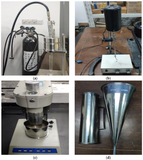
Figure 13.
The experimental equipment of lubricating mud: (a) adhesion coefficient instrument, (b) electric agitator; (c) rotational viscometer; (d) funnel viscometer.
4.5.2. Pipeline Sending Ditch
The sending mode of the steel pipe was mediated by the combination of a pipeline sending ditch and roller. The size of the sending ditch (Figure 14) was 2 m in the upper port, 1.5 m in the lower port, and 1.2 m in depth. Before digging the sending ditch, the slope of the sending ditch needed to be calculated, especially the section where the pipeline entered the hole, to ensure that the pipeline could enter the hole and pass through it smoothly. The pipeline was placed in the sending ditch in a floating state to avoid direct contact between the pipeline and the ground, effectively reducing its friction resistance, and ensuring that the pipeline was not damaged during the dragging process.
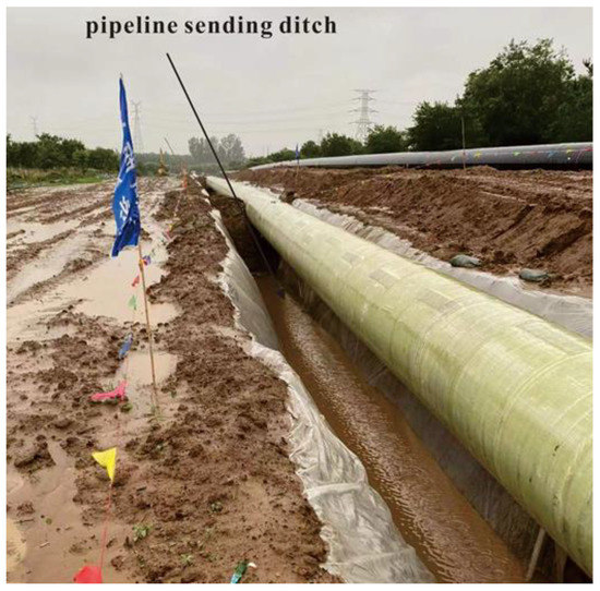
Figure 14.
Pipeline sending ditch.
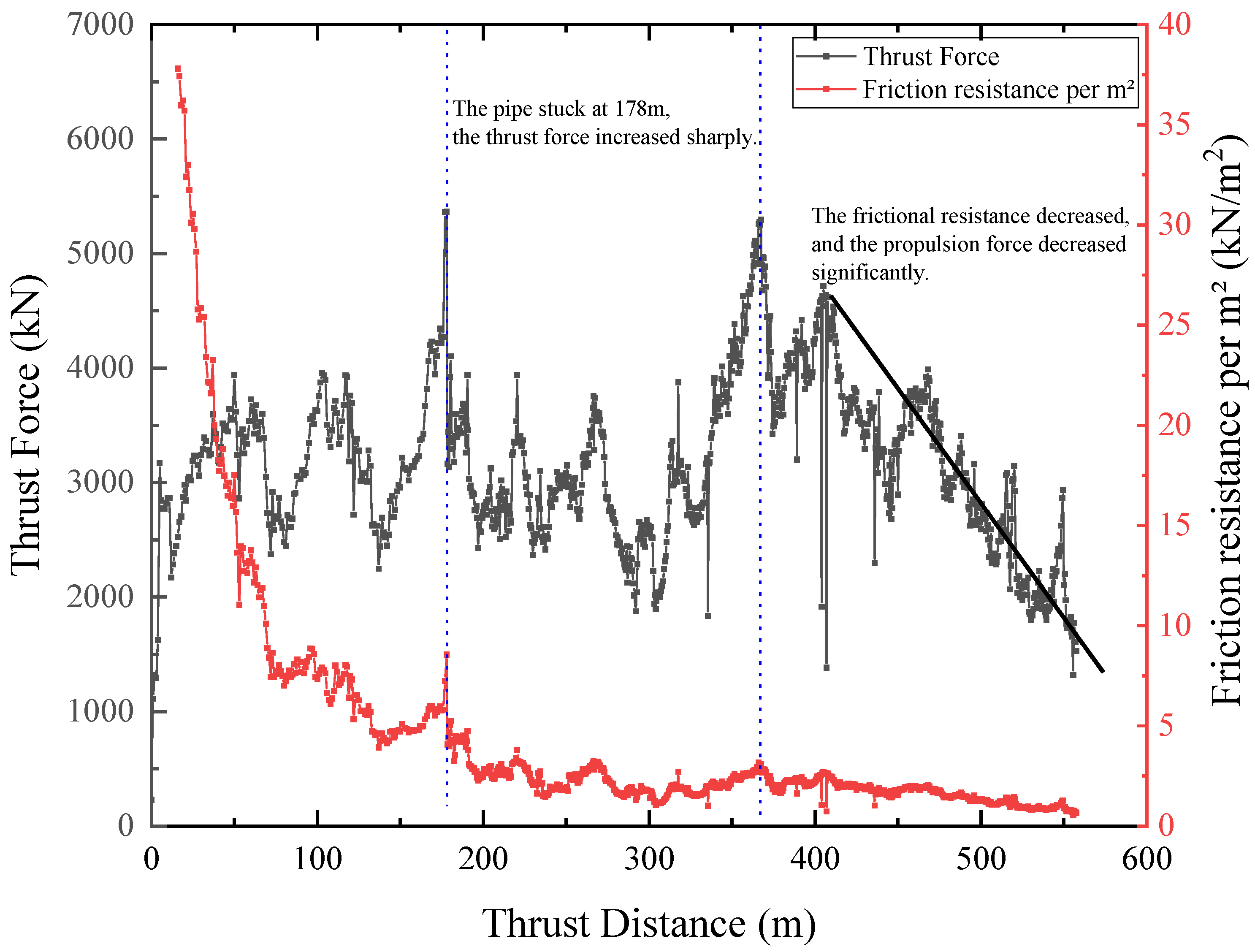
5. Analysis of Thrust Force
In the analysis of the thrust force of rapid jacking and pipeline laying (Figure 15), the pipe jacking force model can be derived from [16], as a function of the face resistance and the frictional resistance along the pipeline. Unlike pipe jacking, this method welds the pipeline together before starting to advance, and even a pipeline without the advancing tunnel would produce frictional resistance with the ground and the sending ditch.
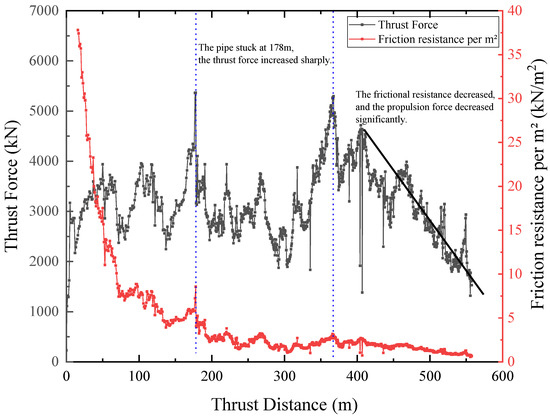
Figure 15.
The thrust force of the construction.
The thrust force first increased at 178 m, when the boring machine was located at the junction of silty clay and the pebble layer; the front end of the boring machine entered the pebble layer, and the attitude changed. The vertical direction of the pipeline deviated from the axis greatly, resulting in a sharp increase in the friction around the pipe, which prevented the whole pipeline from re-thrusting.
When thrusting to 290 m, the boring machine was at the lowest point of the propulsion trajectory, and the propulsion force was at a low value. As the attitude of the boring machine was adjusted upward, the curvature became smaller, and the additional coefficient of the propulsion force became larger, resulting in a gradual increase in the propulsion force. At about 362 m, the water and soil pressure in front of the machine head reached a maximum of 0.7 MPa at this time, thereby quickly reattaining the thrust force. At this time, the boring machine was located at the junction of the silty clay and the fine sand layer, and the fine sand entered the annular gap at the front end of the pipeline, leading to a large friction resistance. Upon adding grouting to the annular gap, the frictional resistance began to decrease.
As the propulsion mileage increased and the burial depth gradually decreased, the thrust force decreased, and the frictional resistance per unit area gradually decreased to less than 2 kN/m2. This was due to mud lubrication, stabilizing the soil and floating pipes. In the process of forming a stable mud jacket, the frictional resistance per unit area of the pipe wall gradually decreased to less than 2 kN/m2. The presence of mud not only reduced the friction factor between the outer wall of the pipe and the soil, but also reduced the earth pressure acting on the pipe by infiltrating the surrounding soil to form a mixed mud jacket wrapping the pipe. Due to the length of the rapid laying and jacking machine, when the jacking distance was less than 100 m, it was observed that the friction resistance of the pipe in the state where the mud jacket was not fully formed was large, and it could even reach 2–4 times the friction resistance value in the stable state of the mud jacket.
6. Conclusions
6.1. Summary
The rapid jacking and pipeline laying method combines the advantages of horizontal directional drilling and pipe jacking, leading to the development of a new trenchless construction method, which can enable the pipeline to cross obstacles such as rivers, lakes, mountains, and roads. The successful application of this method in this project solved the problems of large pipeline axis deviation and complex construction geology. At the same time, the pipe pulling technology after pipe clamping was enabled, and the project was successful. During the construction, the following findings could be noted:
- (1)
- Due to the process particularity of rapid jacking and pipeline laying, a support form with a short construction period, low cost, and easy removal could be selected in the construction of the launching shaft, effectively shortening the construction period and reducing the cost. After construction was completed, this was convenient to complete site leveling and equipment reuse.
- (2)
- When crossing geologically diverse and complex conditions, especially through gravel layers, a slurry balance type boring machine should be selected, the opening rate of the boring machine should be appropriately increased, the hob and scraper should be used together, and the secondary crushing bin should be equipped to crush the larger solitary stone and unpredictable obstacles, carrying the face through the circulating mud.
- (3)
- In the pipeline propulsion process, a gyroscope guidance system and propulsion fixed distance were used to control the propulsion trajectory in the curve propulsion process through a combination of manual measurement and review. Due to the complex geological conditions and the difficulty of correction, there was a certain error in the vertical direction in the propulsion process of this project, but there was almost no error in the horizontal direction, and the vertical and horizontal errors were controlled in 20 cm increments during completion. Therefore, this guidance system is suitable for any direct pipe laying method.
- (4)
- When the thrust equipment provides thrust force, it can also provide the same magnitude of tension. When the pipe is stuck in the process of pipe propulsion, the pipe can be pulled back through the contraction of the cylinder of the thrust equipment at any time.
- (5)
- In the process of laying oil and gas pipelines using the rapid jacking and pipeline laying method, there is no reserved grouting hole around the pipeline. The annular lubrication grouting is reserved through the grouting hole in front of the boring machine and the grouting hole in the hole. Therefore, the annular lubrication mud should be stopped regularly to supplement the slurry. Because of the overall advancement of the pipeline, rent reduction measures should be designed for the rear pipeline. An overhead and pipeline sending ditch floating pipeline can reduce the friction resistance and ensure that the outer coating of the pipeline is not destroyed.
- (6)
- The construction unit price of the rapid jacking and pipeline laying method in this project was about 2000 USD/m, with about 40% allocated to pipe jacking and 20% allocated to shield construction, which is slightly higher than the cost of horizontal directional drilling. However, the project passed through a pebble layer, which is very difficult for horizontal directional drilling technology. Considering the technology using horizontal directional drilling with casing pipes, the cost would be greater than the rapid jacking and pipeline laying method, in addition to associated construction risks. Therefore, the rapid jacking and pipeline laying method was the most suitable construction technology for this project with its advantages of high construction efficiency, low cost, and small footprint.
6.2. Conclusions
Through the successful implementation of this project, it was verified that the direct pipe laying method has the advantages of low cost and fast speed in oil and gas pipeline crossing projects, which will become more and more favored by the trenchless industry, and will also become a powerful supplement to the construction methods of shield, pipe jacking, and directional drilling in the trenchless field, providing new ideas for the construction of oil and gas pipelines in China and abroad.
With the promotion of this technology, research on the force characteristics and thrust force calculation model of the rapid jacking and pipeline laying method will continue.
Author Contributions
Conceptualization, T.X. and C.Z.; Data curation, T.X., L.W. and Y.Z.; Formal analysis, T.X. and K.L.; Funding acquisition, L.W. and P.Z.; Investigation, T.X.; Methodology, T.X. and C.Z.; Project administration, L.W., P.Z. and Y.Q.; Validation, T.X. and X.F.; Visualization, X.F.; Writing—original draft, T.X., Y.Z. and K.L.; Writing—review & editing, Y.Z. and K.L. All authors have read and agreed to the published version of the manuscript.
Funding
This research received no external funding.
Institutional Review Board Statement
Not applicable.
Informed Consent Statement
Not applicable.
Data Availability Statement
Not applicable.
Conflicts of Interest
The authors declare no conflict of interest.
References
- Wang, H. Oil and gas pipeline construction status analysis and optimization method exploration. Chin. J. China Pet. Chem. Stand. Qual. 2021, 41, 2. [Google Scholar]
- Lu, H.; Matthews, J.; Iseley, T. How does trenchless technology make pipeline construction greener? A comprehensive carbon footprint and energy consumption analysis. J. Clean. Prod. 2020, 261, 121215. [Google Scholar] [CrossRef]
- Najafi, M. Trenchless Technology: Planning, Equipment, and Methods; McGraw-Hill: New York, NY, USA, 2013. [Google Scholar]
- Lu, H.; Behbahani, S.; Azimi, M.; Matthews, J.; Han, S.; Iseley, T. Trenchless Construction Technologies for Oil and Gas Pipelines: State-of-the-Art Review. J. Constr. Eng. Manag. 2020, 146, 03120001. [Google Scholar] [CrossRef]
- Yan, X.; Ariaratnam, S.T.; Dong, S.; Zeng, C. Horizontal directional drilling: State-of-the-art review of theory and applications. Tunn. Undergr. Space Technol. 2018, 72, 162–173. [Google Scholar] [CrossRef]
- Li, C.; Zhong, Z.; Liu, X.; Tu, Y.; He, G. Numerical simulation for an estimation of the jacking force of ul-tra-long-distance pipe jacking with frictional property testing at the rock mass–pipe interface. Tunn. Undergr. Space Technol. 2019, 89, 205–221. [Google Scholar] [CrossRef]
- He, X.-C.; Xu, Y.-S.; Shen, S.-L.; Zhou, A.-N. Geological environment problems during metro shield tunnelling in Shenzhen, China. Arab. J. Geosci. 2020, 13, 87. [Google Scholar] [CrossRef]
- Kantemirov, I.F.; Kabirov, R.R. Modern trenchless technologies in the construction of gas and oil pipeline crossings. direct pipe technology. Synerg. Sci. 2021, 61, 94–100. [Google Scholar]
- Lamont, C.; Ross, M.; Lueke, J. Thickwood Trunk Sewer—Direct Pipe Installation. In Pipelines; Asce Library: Reston, VA, USA, 2021; pp. 312–320. [Google Scholar] [CrossRef]
- Robison, J.L.; Arens, N.A. Direct Pipe Construction: An Engineering Perspective on Quality Assurance. In Proceedings of the Pipelines 2017 Conference, Phoenix, AZ, USA, 6–9 August 2017; pp. 227–238. [Google Scholar]
- Wang, L. Construction Technology and Application of the Direct Pipe Method. Chin. J. Tunn. Constr. 2018, 38, 1566–1572. [Google Scholar]
- Liu, X.M.; Tan, M.X.; Li, Q.Y.; Xiang, Y.Q. Application of direct pipe laying in sandy stratum large diameter pipe-lines. Nat. Gas Oil 2018, 36, 5–8. [Google Scholar]
- GB 50568-2010[S]; Standard for Oil and Gas Field and Pipeline Investigation of Geotechnical Engineering. China Planning Press: Beijing, China, 2010; pp. 83–85.
- Staheli, K. Jacking Force Prediction: An Interface Friction Approach Based on Pipe Surface Roughness; Georgia Institute of Technology: Atlanta, GA, USA, 2006. [Google Scholar]
- Zhang, P.; Ma, B.; Zeng, C.; Xie, H.; Li, X.; Wang, D. Key techniques for the largest curved pipe jacking roof to date: A case study of Gongbei tunnel. Tunn. Undergr. Space Technol. 2016, 59, 134–145. [Google Scholar] [CrossRef]
- Pruiksma, J.P.; Pfeff, D.; Kruse, H.M.G. The calculation of the thrust force for pipeline installation using the Direct Pipe method. In Proceedings of the 7th Pipeline Technology Conference, Hannover, Germany, 28–30 March 2012. [Google Scholar]


Publisher’s Note: MDPI stays neutral with regard to jurisdictional claims in published maps and institutional affiliations. |
© 2022 by the authors. Licensee MDPI, Basel, Switzerland. This article is an open access article distributed under the terms and conditions of the Creative Commons Attribution (CC BY) license (https://creativecommons.org/licenses/by/4.0/).