Article

Analysis of the Operation of Cascade Current Transformers for Measurements of Short-Circuit Currents with a Non-Periodic Component with a Large Time Constant of Its Decay

1
Institute of Mechatronics and Information Systems, Lodz University of Technology, 90-924 Lodz, Poland
2
TRANSFORMEX Limited Liability Company, 04-965 Warsaw, Poland
*
Author to whom correspondence should be addressed.
Energies 2022, 15(8), 2925; https://doi.org/10.3390/en15082925
Submission received: 30 January 2022 / Revised: 9 April 2022 / Accepted: 11 April 2022 / Published: 15 April 2022
(This article belongs to the Section F: Electrical Engineering)

Abstract

:
Simulations of emergency states and tests of resistance of electrical devices to emergencies are performed in specialized high-power laboratories, the so-called short-circuit laboratories. For most electrical power devices, such measurements are required by international standards. The basic equipment of short-circuit testing laboratories consists of current transformers for measuring short-circuit currents. These transformers should not only enable the accurate conversion of sinusoidal currents—which is typical for conventional current transformers, but also asymmetrical short-circuit currents containing an aperiodic component, which classic current transformers cannot reproduce. Therefore, manufacturers and designers try to meet the market demands and design these special class 0.2 current transformers. To meet the high technical requirements, the field-circuit method with three-dimensional space–time analysis of electromagnetic fields was used during design, considering physical phenomena in ferromagnetic cores (i.e., hysteresis and eddy current losses) and the load of the secondary winding of the current transformer by the measurement system. The article presents simulations of secondary currents for the short-circuit current transformer model, and the results were confirmed by measurements and oscillograms of the currents flowing in the windings of the real model. The prototype of the designed short-circuit transformer meets the IEC/EN standard requirements. When measuring harmonic currents, the transformation errors meet the requirements of class 0.2. During the short-circuit current waveforms, the maximum instantaneous peak error does not exceed 1% of the error for all the subsequent maxima of the current waveform during the specified transient switching cycle. In comparison, the standard allows this error to be 10%.

1. Introduction

Short-circuit testing laboratories enable the performance of basic design tests and tests, allowing the use of automatic power protection in the power industry. Classic current transformers are used to convert sinusoidal alternating currents. Problems occur in the measurement of asymmetrical currents when the measured current contains a decaying non-periodic component with a time constant. The non-periodic component of the current causes saturation of the current transformer’s ferromagnetic cores and leads to significant transformation errors. Therefore, the waveforms of the short-circuit currents can only be processed by current transformers of a special design. So, the essential equipment of these laboratories consists of short-circuit current transformers.
Current transformers of this type are used in short-circuit laboratories and protection automation devices.
Each measuring or protection current transformer, as part of a measuring or protection system, must meet the requirements of the International Electrotechnical Commission and the European Standard (IEC/EN) [1,2]. The IEC/EN standard also covers terminologies and symbols in the field.
Under normal operating conditions, the current transformer can be described by a classic equivalent circuit, which has its source in the theory of transformer operation. However, the equivalent circuit with constant parameters does not consider a number of phenomena related to saturation and the mechanism of the occurrence of core losses. For this reason, there are several publications that introduce some improvements to this scheme; above all, these publications allow the approximate saturation effect and hysteresis to be considered [3]. In addition, many works were related to the transformation problem for waveforms that were distorted and with a frequency higher than 50 Hz [4,5,6,7,8]. In the analyzed case, we additionally deal with two winded cores connected to each other, which forces the interaction of their leakage fluxes to be taken into account.The classic equivalent scheme is not able to reproduce the phenomena related to the complicated spatial distribution of the electromagnetic field.
A big problem is the saturation of the current transformer cores, especially at high currents. A number of scientific publications deal with this problem [9,10,11,12]. There are two approaches: one using different signal processing techniques applied to distorted waveforms; and the other using a cascade structure, which is much more resistant than a single transformer with the same parameters.
However, short-circuit current transformers, in addition to testing transformation errors in steady states, should also be tested during short circuits, i.e., with asymmetrical short-circuit currents, as in power systems. The short-circuit test laboratory research in the field of symmetrical and asymmetric short-circuit currents, the decay time constant of the non-periodic short-circuit component, the asymmetric peak factor, and various types of short-circuit tests were performed on multiple devices operating in power systems and on current transformers [13,14]. The article [15] describes a method of checking the accuracy of current transformers for measuring short-circuit currents and gives examples of oscillograms.
The testing can only be performed after building an expensive prototype, in this case, of a special short-circuit current transformer for laboratory operation. This article aims to show that the properties of short-circuit current transformers can be assessed at the design stage.
The cascade consists of a limited number of transformers; the primary winding of each after the first is powered by the secondary of the previous one. The cascade is used in power and voltage transformers [16,17,18,19].
The cascade structures are used at high currents or voltage values. A secondary winding with thousands of turns would be necessary through a current transformer with a large winding ratio and single-wire structures. This would result in a significant increase in the dimensions of the current transformer and would be very laborious and expensive. Moreover, in the case of the accidental opening of the secondary terminals of the current transformer, a very high voltage would be induced in the secondary winding [19,20]. With the use of numerical methods [21,22,23,24,25,26,27,28] and space–time analysis of 3D electromagnetic fields, it is possible to check the operation of a short-circuit current transformer during short circuits before testing a prototype at the design change, i.e., the currents at an asymmetrical short circuit [29,30,31,32].
The applied field-circuit method [22,32] considers the phenomena resulting from the load on the secondary circuit of the current transformer and the physical phenomena in the core (i.e., hysteresis and eddy current losses); this allows the study of the secondary current waveform during a short circuit in the primary circuit. Moreover, this method gives much more accurate results than the analytical methods. The tests were conducted at the short-circuit testing laboratory in accordance with the method described in the article for checking the accuracy of current transformers for measuring short-circuit currents [15]. The obtained oscillograms were used for comparison with the calculated results.
The following parts of this article are structured as follows.
Section 2 presents the geometrical model of the 50 kA/5 A short-circuit current transformer design, the magnetization characteristics, and the specific power loss characteristics of the transformer steel used in the cores. Section 3 describes the mathematical model and computer simulation data. Section 4 compares the results of the simulation and experimental tests. A comparison of the measured and calculated transformation error and oscillograms of the secondary currents of the short-circuit transformer model with comments on accuracy are presented. The practical conclusions of the research are presented in Section 5.

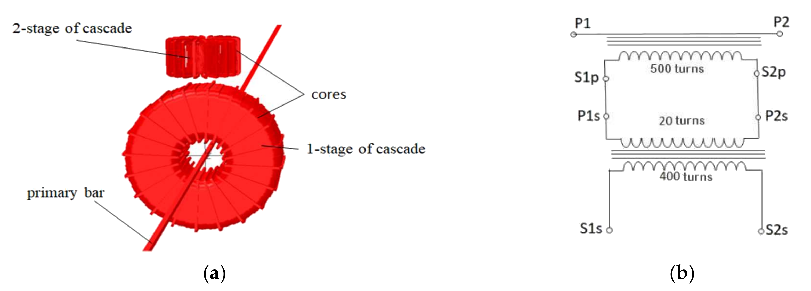
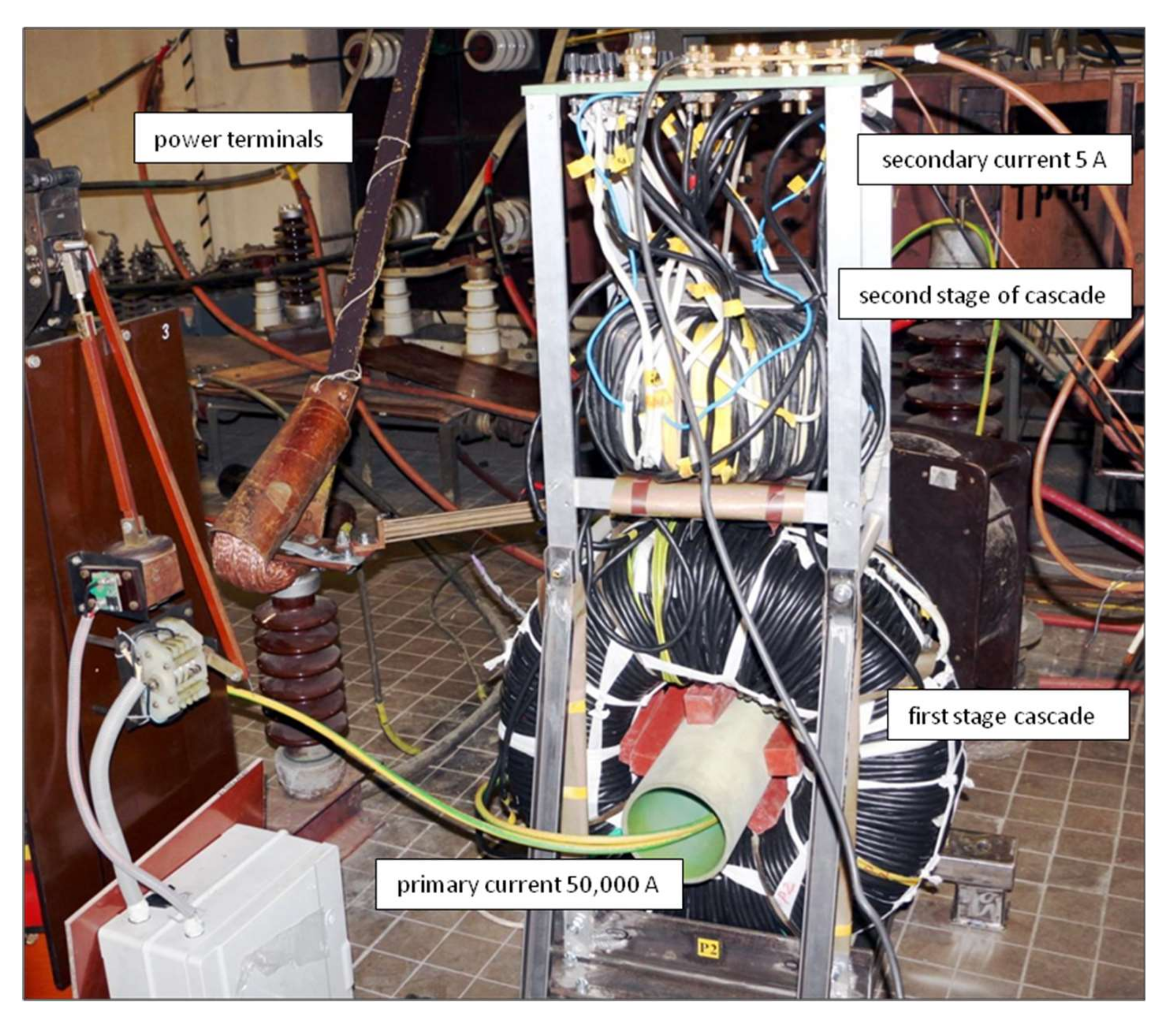
2. Construction of Cascade Current Transformers for Measuring Short-Circuit Currents

The article presents the assessment of the operating accuracy of a 50 kA/5 A cascade current transformer for short-circuit current measurements, with two cores and a large number of 920 turns. The calculations by the field-circuit method were performed based on the numerical finite element method, and their results were compared with the tests of the real model.
Laboratory equipment short-circuit tests of elements operating in power systems with a high time constant (such as bus bars leading the power supply from the power plant and circuit breakers near the generator) must be equipped with short-circuit current transformers, tested for short-circuit conditions at a high time constant of approximately 200 ms.
The analysis of the operation of a 50 kA/5 A cascade current transformer for measuring short-circuit currents was conducted. Designed and manufactured by TRANSFORMERS, the prototype of the current transformer has a sleeve structure and ring-shaped cores without gaps. This current transformer’s two spiral magnetic cores are made of cold-rolled ET 120-30 steel sheets.
Basic parameters:
  • rated insulation voltage: 30 kV;
  • primary rated current: 50 kA;
  • rated secondary current: 5 A;
  • rated power: 20 VA;
  • accuracy class: 0.2;
  • decay time constant of the non-periodic component of the short-circuit current;
  • Tp = 200 ms;
  • continuous operation: up to 20 kA.
Figure 1 shows a 3D model of the tested current transformer (50 kA/5 A).
The manufacturers of ferromagnetic sheets do not always provide the characteristics of the magnetism in the saturation part. On the other hand, computer programs during iteration follow the characteristics that are also in the saturation part. Therefore, a characteristic B = f (H) above the value at which the device is working is required. This is why, using the Froelich method, verified and used many times by various authors [33,34], the magnetization curve was extended to the value of induction in the saturation range.
Figure 2 shows the magnetization curve and the specific power loss characteristics of the magnetic cores used in the tested current transformer. The hypothetical σ conductivity of the laminated core was determined based on the material-specific power loss characteristics, core dimensions, and magnetic induction distribution. This method, considering the power losses in laminated cores, has been used by various authors [23,28,35,36,37].

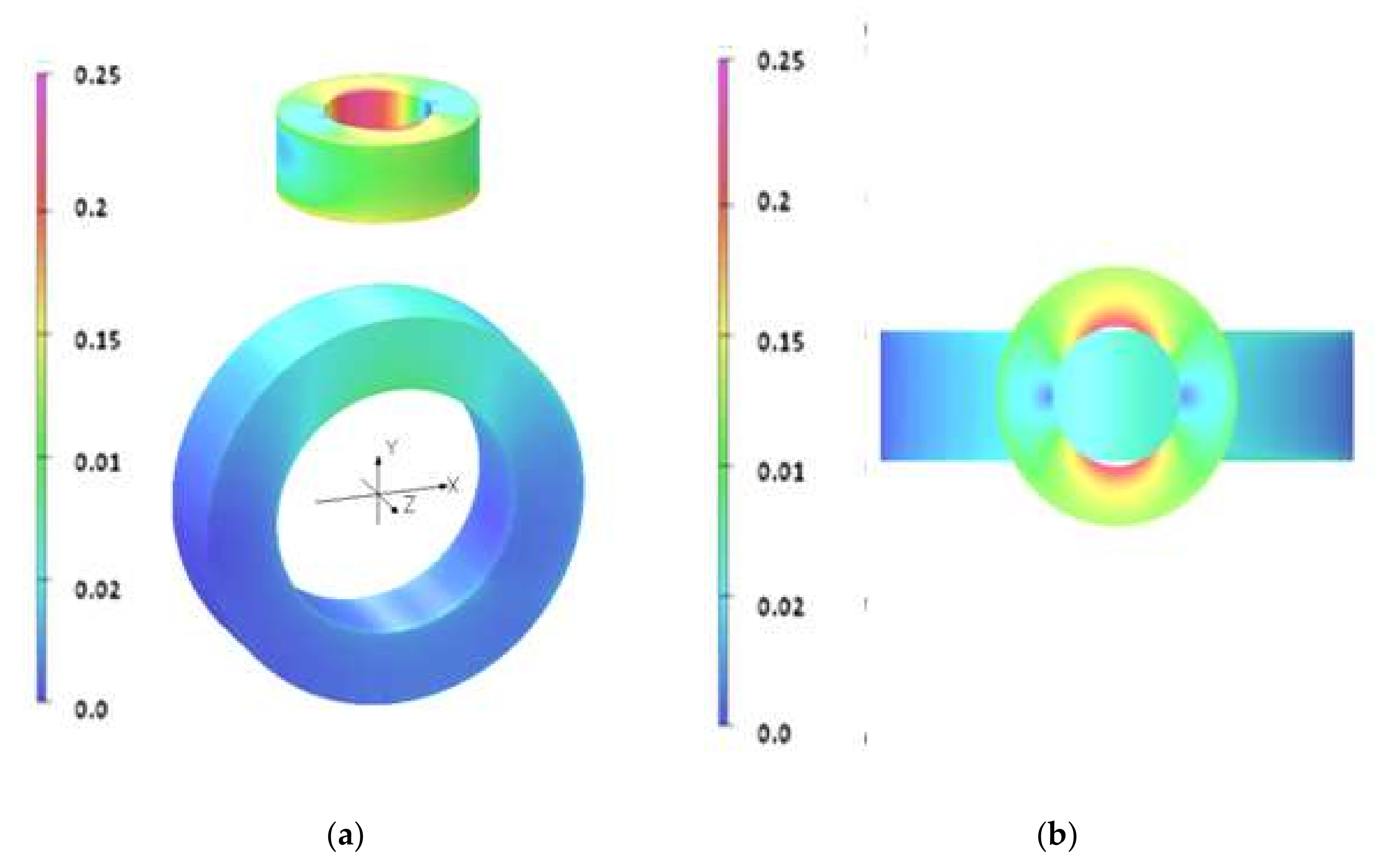
3. Mathematical Model of the Current Transformer

The calculation of errors of the current transformer at load, as required by the standard [1,2], was performed using the 3D field-circuit method, which enables the calculation of the currents induced in the secondary circuit (similar to articles [23,24,25,26,27,28,29]).
The steady-state harmonic analysis was performed using the Helmholtz-type equation for a harmonic electromagnetic field.
2 A _ μ 1 μ × × A _ j ω μ σ A _ = μ J p ¯
Ψ _ = n s S s Ω s A _ l s d v
U _ s = j ω Ψ _ = R + j ω L I _ s
where A is the complex magnetic vector potential (complex magnetic induction B = ▽ × A), Jp is the complex vector of primary current density); Ψ is the complex magnetic flux passing through the secondary coil; Is and Us are the complex secondary current and voltage, respectively; and ω is the angular frequency of the voltage. The boundary conditions are A × n = 0, where n is the unit normal vector to the boundary and V = 0 for the electric scalar potential on the border of the entire system with the surrounding air.
R and L are the load resistance and inductance of the secondary winding current transformer, respectively; µ is the permeability; σ is the conductivity of materials; and ns and Ss are the number of turns and the cross-sectional area of this coil, respectively. Ωs is the volume of the secondary winding, and ls is the unit tangent vector along the direction of the secondary current in the winding.
Calculations of the secondary current as a function of time at the short-circuit current in the primary circuit of the current transformer were performed using the field-circuit method with three-dimensional space–time analysis [30,31,32,33].
The diffusion-type equation describes the electromagnetic field in electrical devices at transient.
× 1 μ   × A = σ A t g r a d V
Ψ = n s S s Ω s A l s d v
u s = d Ψ d t = R i s + L d i s d t
where A, Ψ, us, and is are quantities varying in time, magnetic vector potential, flux, and secondary voltage and secondary current; B = ▽ × A; and the boundary conditions are A × n = 0 and V = 0 for an electric scalar potential at the boundary of the entire system with the surrounding air. The rest of the symbols are the same as Equations (1) to (3).
Even small losses in the laminated cores significantly impact the errors of such precise devices as instrument transformers. Therefore, the average value of the conductivity σ of the cores was entered. The loss in a core phenomenon (i.e., hysteresis and eddy current losses) was considered using homogenization and by calculating the equivalent conductivity σ of the cores depending on the pre-calculated magnetic induction distribution in the cores at σ = 0 and the loss characteristics of the magnetic material.
Both methods, being steady-state and transient analysis, use the magnetization curve and the hypothetical specific σ conductivity of the laminated cores based on the characteristics shown in Figure 2.
The field distributions in the cascade current transformer were calculated at a steady state using the ELEKTRA STEADY-STATE module. In contrast, the ELEKTRA TRANSIENT module of the professional software OPERA 3D was used during short circuits.
Accuracy analysis carried out by refining the mesh for the 3D model of the current transformer with 920 turns gave the result of 101,627,377 elements. The space–time analysis was performed with a time step of 5.00 ms.
The secondary current was calculated and used to obtain the characteristics of the transformation errors, and to draw the secondary current waveforms during the short circuit. The obtained results were used for comparison with the measurements.

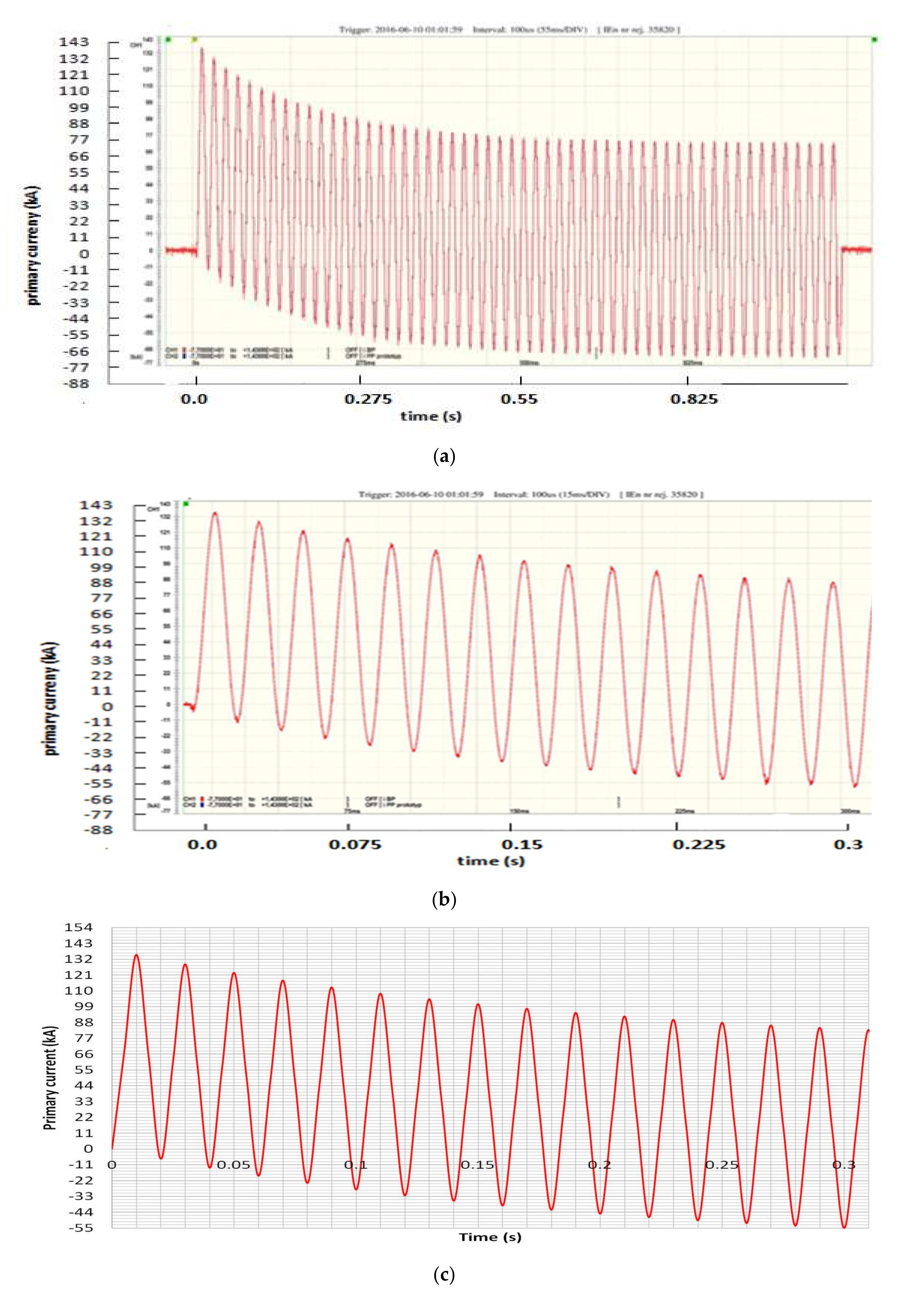
4. The Results of the Calculations and Tests

The calculations and measurements of the prototype transformation errors were performed under the same conditions, and the results were compared.
The values of short-circuit currents used to test the resistance to dynamic short circuits are much higher than the value of symmetrical currents.
The starting point of the research was to determine the accuracy of the tested current transformer’s model for the transformation of a sinusoidal current with a frequency of 50 Hz in accordance with the IEC/EN standard. The IEC/EN standard defines transformation errors as the current error [2]:
Δ I = I s K n I p I p 100 %
where Kn is the nominal currents ratio, and phase displacement between the waveform of the secondary and primary currents:
δ i = φ i s φ i p
As a result of the performed calculations and measurements, the current errors and phase displacement of the current transformer at different supply currents were compared (Table 1). The test was carried out in the laboratory of TRANSFORMEX. On this basis, in both cases, the prototype class of a short-circuit transformer was determined, which according to the standard [2], was 0.2.
Figure 3 shows the magnetic field distribution in cores of the current transformer, obtained by analyzing the field-circuit method at a rated primary current of 50 kA in a steady state.
The characteristics of the current and phase displacement errors were compared, obtained from the calculations and measurements of a 50 kA/5 A cascade current transformer with toroidal cores (Figure 1). Figure 4 shows a graphical comparison of the calculated and measured transformation errors of the tested current transformer (Table 1) at the steady state with the limits set by the IEC/EN standards for class 0.2. The current error and phase displasement of the transformer are in the class defined by the standards as 0.2.
The results of the measurements and calculations of the transformation errors using field methods in steady states are convergent. A cascade short-circuit transformer with a sinusoidal supply has much smaller transformation errors than the limits of class 0.2 (Table 1). Moreover, as shown in Figure 3, both cores of the cascade are not saturated, and the magnetic induction values reach a maximum of 0.25 T.
A transient state appears during a short circuit in the RL type system, i.e., a sine wave with an asymmetric waveform superimposed. Calculations and tests of the instantaneous secondary current as a function of time were performed for the worst transient conditions under load. Estimates of the instantaneous secondary current versus time were performed in the transient state for a load R = 0.88 Ω, a specified primary time constant Tp = 190 ms, and a rated symmetrical short-circuit current ratio Kssc = 2.76.
The primary current was:
i p = 69.4 c o s 314.16 t e 5.26 t   k A  
The tests were carried out in the short-circuit laboratory (Figure 5). The time constant was set to 190 ms in the test system, and the load was R = 0.88 Ω. It was agreed that the short-circuit current would be switched on with a large rated symmetrical short-circuit current ratio Kssc = 2.76. Such extreme test parameters provided knowledge about the phenomena occurring in the cascades of current transformers at the limit values.
The errors made during the transformation of the short-circuit current waveform are so small that if the secondary current waveform is multiplied by the current ratio, the waveforms practically coincide.
Similarly, to determine the errors of the current transformer in steady states, the errors made during the transformation of the short-circuit current waveform were calculated for the maximum values of the individual current peaks. The instantaneous peak error for selected peaks was calculated using the formula [2]:
ε ^ = i ε ^ 2 I p s c 100 %
where the instantaneous current error is i ε = K n i s i p
The transient-state test results for the prototype 50 kA/5 A current transformer are shown in Table 2, and the diagrams in Figure 6, Figure 7, Figure 8 and Figure 9 are shown.
For transient protection (TP) current transformers with a core without an air gap, the instantaneous peak error ε ^   may not exceed 10%, according to the IEC/EN standard. This error did not even exceed 1%. The discussed transformer meets this condition (Figure 6).
During operation at the rated current, the induction in the second core of the cascade was 0.26 T (Figure 3). In contrast, during a short circuit, the maximum magnetic induction reached 1.47 T at the highest value of the primary current and then dropped at the second maximum to 1.27 T (Figure 8). The value of the induction at 1.47 T is lower than the saturation induction. The short-circuit current transformer meets the requirement not to distort the tested waveform (Figure 6 and Figure 7).
The current error of the 50 kA/5 A short-circuit current transformer for the maximum current 50 kA does not exceed the limit specified for the accuracy class 0.2 established by the standard for a steady state (Figure 4). It also meets the standard requirements for transformers of the transient protection (TP) type; i.e., the maximum instantaneous peak error may not exceed 10% (Figure 9).
The results show the advisability of using numerical methods before building an expensive prototype.

5. Conclusions

Since devices such as short-circuit current transformers are expensive, and since it is difficult to calculate the effects of the design using analytical methods, space–time analysis was used, which gives accurate results; thus, this predicts the experimental results with high accuracy.
Current transformers are precise devices and a failure to consider core losses basically disqualifies calculations, especially the phase displacement values, the limits of which for various classes are given in minutes. Even small losses in laminated cores significantly impact the errors of such precise devices as current transformers. Therefore, an important aspect is to consider the lamination of the cores by introducing a homogeneous conductivity σ that models the losses in the cores during the calculations. The core loss phenomenon (i.e., hysteresis and eddy current losses) was considered when calculating the equivalent conductivity of the cores, depending on the previously estimated magnetic induction distribution in the cores at σ = 0 and the loss characteristics of the magnetic material (Figure 2).
The applied method was confirmed by the tests, and the obtained results in both cases meet the requirements of the IEC/EN standard. The short-circuit current transformer meets the conditions of class 0.2 (Table 1) when measuring sinusoidal waveforms. It also meets the requirements for transient protection (TP) transformers; that is, the maximum instantaneous peak error may not exceed 10% of the error for all the subsequent maxima of the current waveform during the specified transient switching cycle. This error did not even exceed 1% (Figure 9). The phase displacement for short-circuit current transformers during short-circuits is practically irrelevant and the standards do not allow it.
The compatibility of the calculations and tests confirms the possibility of using the field-circuit method to assess the accuracy of these special current transformers at the design stage. In comparison, physical tests require the construction of an expensive prototype current transformer.
It was advantageous to develop such a model of a digital cascade current transformer. In this way, it was possible to obtain information about the peak value of the secondary currents of both stages when a sinusoidal current or an asymmetrical current with a non-periodic component flow through the primary winding, at different values of the time constant of the primary circuit.
By changing individual elements of the current transformer model, this approach helps us to obtain guidelines for the construction of other short-circuit transformer structures with different current ratios and other time constants. The cascade design ensures that the transformer works in the absence of core saturation and is the best choice for this type of application.

Author Contributions

Conceptualization: J.O. and E.L.; methodology: E.L. and J.O.; software: E.L.; validation: E.L. and J.O.; formal analysis: E.L.; investigation: E.L. and J.O.; resources: E.L. and J.O.; data curation: E.L. and J.O.; writing—original draft preparation: E.L.; writing—review and editing: E.L.; supervision: E.L. All authors have read and agreed to the published version of the manuscript.

Funding

This research received no external funding.

Institutional Review Board Statement

Not applicable.

Informed Consent Statement

Not applicable.

Data Availability Statement

The data presented in this study are available on request from the corresponding author. The computer data are not publicly available because they are not suitable for use by another researcher.

Conflicts of Interest

The author declares no conflict of interest.

References

  1. IEC/EN 61869-1; Instrument Transformers—Part 1: General Requirements. Electrotechnical Commission: Geneva, Switzerland, 2009.
  2. IEC/EN 61869-2; Instrument Transformers—Part 2: Additional Requirements for Current Transformers. Electrotechnical Commission: Geneva, Switzerland, 2013.
  3. Torre, F.D.; Faifer, M.; Morando, A.P.; Ottoboni, R.; Che, C. Instrument transformers: A different approach to their modeling. IEEE Int. Workshop Appl. Meas. Power Syst. AMPS 2011, 37–42. [Google Scholar] [CrossRef]
  4. Chen, Y.; Huang, Z.; Duan, Z.; Fu, P.; Zhou, G.; Luo, L. A four-winding inductive filtering transformer to enhance power quality in a high-voltage distribution network supplying nonlinear loads. Energies 2019, 12, 2021. [Google Scholar] [CrossRef] [Green Version]
  5. Leal, A.C.; Trujillo, C.; Piedrahita, F.S. Comparative of power calculation methods for single-phase systems under sinusoidal and non-sinusoidal operation. Energies 2020, 13, 4322. [Google Scholar] [CrossRef]
  6. Szewczyk, M.; Kutorasinski, K.; Pawlowski, J.; Piasecki, W.; Florkowski, M. Advanced modeling of magnetic cores for damping of high-frequency power system transients. IEEE Trans. Power Deliv. 2016, 31, 2431–2439. [Google Scholar] [CrossRef]
  7. Das, N.; Kazimierczuk, M.K. An overview of technical challenges in the design of current transformers. In Proceedings of the Electrical Insulation Conference and Electrical Manufacturing Expo; Indianapolis, IN, USA, 2005; pp. 369–377. [Google Scholar] [CrossRef]
  8. Faifer, M.; Laurano, C.; Ottoboni, R.; Toscani, S.; Zanoni, M. Harmonic distortion compensation in voltage transformers for improved power quality measurements. IEEE Trans. Instrum. Meas. 2019, 68, 3823–3830. [Google Scholar] [CrossRef]
  9. Pan, J.; Vu, K.; Hu, Y. An efficient compensation algorithm for current transformer saturation effects. IEEE Trans. Power Deliv. 2004, 19, 1623–1628. [Google Scholar] [CrossRef]
  10. El-amin, M.; Al-abbas, N.H. Saturation of current transformers and its impact on digital overcurrent relays. In Proceedings of the IEEE/PES Transmission & Distribution Conference and Exposition: Latin America, Caracas, Venezuela, 15–18 August 2006; pp. 1–6. [Google Scholar] [CrossRef]
  11. Jian-Dong, D.; Yang, L.; Zhuan-Ting, J.; Hao, L.; Qing, Z.X.; Yang, Z.Y. Empirical analysis on transient saturation characteristic of current transformer. In Proceedings of the IEEE Transportation Electrification Conference and Expo., Asia-Pacific (ITEC Asia-Pacific), Harbin, China, 7–10 August 2017; pp. 1–6. [Google Scholar] [CrossRef]
  12. Stachel, P.; Schegner, P. Detection and correction of current transformer saturation effects in secondary current signals. In Proceedings of the IEEE Power & Energy Society General Meeting, Calgary, AL, Canada, 26–30 July 2009; pp. 1–6. [Google Scholar] [CrossRef]
  13. Olak, J.; Przybysz, J. Current Converter for Simultaneous Transformation of High and Low Short-Circuit Currents in the High Voltage. Range. Patent P.419126, 13 October 2016. (In Polish). [Google Scholar]
  14. Olak, J.; Olak, A. Medium Voltage Current. Transformer. Patent PL 203053 B1, 11 August 2009. (In Polish). [Google Scholar]
  15. Babiuch, M.; Olak, J. The system of measurement of symmetrical and asymmetric short circuit current with multi range current transformers in conditions of short-circuit testing laboratory. Politechnika Gdańska 2019, 159–162. [Google Scholar] [CrossRef]
  16. Irani, Y.; Lapthorn, A.; Bodger, P. Equivalent circuit model of cascade connected partial core resonant transformers. In Proceedings of the Australasian Universities Power Engineering Conference, Hobart, TAS, Australia, 29 September–3 October 2013; p. 4. [Google Scholar] [CrossRef] [Green Version]
  17. Dash, A.R.; Panda, A.K.; Patel, R.; Penthia, T. Design and implementation of a cascaded transformer coupled multilevel inverter-based shunt active filter under different grid voltage conditions. Inter. Trans. Syst. Elektr. 2018, 29, 20. [Google Scholar] [CrossRef]
  18. Johnston, D.L.; Lucas, H.R. 735-kV cascade style current transformer. IEEE Trans. Power App. Syst. 1967, 86, 1205–1209. [Google Scholar] [CrossRef]
  19. Zhurakhivskyi, A.V.; Kens, Y.A.; Ravlyk, R.O.M.; Ferensovych, Y. Investigation of emergency modes of cascade current transformers after disconnection their secondary circuits. Tech. Electrodyn. 2018, 1, 78–86. [Google Scholar] [CrossRef]
  20. Koszmider, A.; Olak, J.; Piotrowski, Z. Current Transformers; WNT: Warszawa, Poland, 1985; pp. 1–283. ISBN 8320407109. (In Polish) [Google Scholar]
  21. Przybysz, J.; Olak, J.; Piątek, Z. Universal current transformer for accurate measurement of short-circuit currents. Acta Energetica 2017, 1, 101–106. [Google Scholar] [CrossRef]
  22. Amoiralis, E.I.; Georgilakis, P.S.; Tsili, M.A.; Kladas, A.G. Global transformer optimization method using evolutionary design and numerical field computation. IEEE Trans. Magn. 2009, 45, 1720–1723. [Google Scholar] [CrossRef]
  23. Lesniewska, E. Applications of the field analysis during design process of instrument transformers. In Transformers. Analysis, Design, and Measurement; Lopez-Fernandez, X.M., Ertan, B.H., Turowski, J., Eds.; CRC Press Taylor & Francis Group: Boca Raton, FL, USA; London, UK; New York, NY, USA, 2012; pp. 349–380. [Google Scholar]
  24. Dems, M.; Komeza, K. Designing an energy-wide frequency range. IEEE Trans. Ind. Electron. 2021, 69, 4387–4397. [Google Scholar] [CrossRef]
  25. Lesniewska, E.; Jalmuzny, W. The estimation of metrological characteristics of instrument transformers in rated and overcurrent conditions based on the analysis of electromagnetic field. Int. J. Comput. Math. Electr. Electron. Eng. 1992, 11, 209–912. [Google Scholar] [CrossRef]
  26. Asghari, B.; Dinavahi, V.; Rioual, M.; Martinez, J.A.; Iravani, R. Interfacing techniques for electromagnetic field and circuit simulation programs IEEE task force on interfacing techniques for simulation tools. IEEE Trans. Power Deliv. 2009, 24, 939–950. [Google Scholar] [CrossRef]
  27. Lesniewska, E.; Rajchert, R. Application of the field-circuit method for the computation of measurement properties of current transformers with cores consisting of different magnetic materials. IEEE Trans. Magn. 2010, 46, 3778–3782. [Google Scholar] [CrossRef]
  28. Lesniewska, E. Influence of the selection of the core shape and winding arrangement on the accuracy of current transformers with through-going primary cable. Energies 2021, 14, 1932. [Google Scholar] [CrossRef]
  29. Kumbhar, G.B.; Mahajan, S.M. Analysis of short circuit and inrush transients in a current transformer using a field-circuit coupled FE formulation. Int. J. Electr. Power Energy Syst. 2011, 33, 1361–1367. [Google Scholar] [CrossRef]
  30. Lesniewska, E.; Jalmuzny, W. Influence of the number of core air gaps on transient state parameters of TPZ class protective current transformers. IET Sci. Meas. Technol. 2009, 3, 105–112. [Google Scholar] [CrossRef]
  31. Afonso, J.I.; Toscano, P.; Briozzo, I. Current transformer modeling for electromagnetic transient simulation in protection systems. In Proceedings of the IEEE PES Transmission & Distribution Conference and Exhibition—Latin America, Montevideo, Uruguay, 28 September–2 October 2020; pp. 1–6. [Google Scholar] [CrossRef]
  32. Li, C.; Li, Q.; Yao, J.; Liu, M. The characteristics of electromagnetic current transformers with DC bias. In Proceedings of the International Conference on Sustainable Power Generation and Supply, Nanjing, China, 6–7 April 2009; pp. 1–6. [Google Scholar] [CrossRef]
  33. Diez, P.; Webb, J.P. A rational approach to B-H curve representation. IEEE Trans. Magn. 2016, 52, 7203604. [Google Scholar] [CrossRef]
  34. Trutt, F.C.; Erdelyi, E.A.; Hopkins, R.E. Representation of the magnetization characteristic of DC machines for computer use. IEEE Trans. Power Appar. Syst. 1968, 87, 665–669. [Google Scholar] [CrossRef]
  35. Markovic, M.; Perriard, Y.E. Current power losses in a toroidal laminated core with rectangular cross section. In Proceedings of the 12th International Conference on Electrical Machines and Systems, Tokyo, Japan, 15–18 November 2009; pp. 1–4. [Google Scholar]
  36. Poveda-Lerma, A.; Serrano-Callergues, G.; Riera-Guasp, M.; Pineda-Sanchez, M.; Puche-Panadero, R.; Perez-Cruz, J. 3D simulation of a power transformer considering lamination effects. In Proceedings of the 18th International Symposium on Electromagnetic Fields in Mechatronics, Electrical and Electronic Engineering (ISEF) Book of Abstracts, Lodz, Poland, 14–16 September 2017; pp. 1–2. [Google Scholar] [CrossRef]
  37. Kefalas, T.D.; Georgilakis, P.S.; Kladas, A.G.; Souflaris, A.T.; Paparigas, D.G. Multiple grade lamination wound core a novel technique for transformer iron loss minimization using simulated annealing with restarts and an anisotropy model. IEEE Trans. Magn. 2008, 44, 1082–1085. [Google Scholar] [CrossRef] [Green Version]
Figure 1. A 3D geometrical model of the 2-stage cascade current transformer for measuring short-circuit currents 50 kA/5 A (a) and its equivalent electric circuit (b), where P1, P2—primary bar terminals, S1p, S2p—terminals of secondary winding the first stage of cascade, P1s, P2s—terminals of primary winding the second stage of cascade, S1s, S2s—terminals of secondary winding the second stage of cascade.
Energies 15 02925 g001
Figure 2. An ET 120-30 magnetization curve of the magnetic cores of the tested model of the cascade current transformer (a) and the specific power loss characteristics (b).
Energies 15 02925 g002aEnergies 15 02925 g002b
Figure 3. Magnetic flux density (T) distributions in the cores of short-circuit current transformers 50 kA/5 A at the rated primary current of 50 kA in a steady state: side view (a) and top view (b).
Energies 15 02925 g003
Figure 4. A comparison of the characteristics of the current error (a) and phase displacement (b) from calculations and tests for short-circuit transformers 50 kA/5 A.
Energies 15 02925 g004
Figure 5. A prototype of a two-stage cascade current transformer 50 kA/5 A for the short-circuit current measurements during tests on a test stand in a short-circuit test laboratory.
Energies 15 02925 g005
Figure 6. The waveform of the primary short-circuit current with the time constant Tp = 190 ms, Kssc = 2.76, and the load R = 0.88 Ω during the tests: the course of the entire test (a), the course of the first 16 current peaks (b), and the calculations (c) i p = 69.4 cos 314.16 t e 5.26 t   kA .
Energies 15 02925 g006
Figure 7. The calculated waveforms of primary (a) and secondary short-circuit currents in the first stage cascade (coupling winding) (b) and the second stage cascade (c).
Energies 15 02925 g007
Figure 8. The distribution of magnetic flux density (T) in the cores of short-circuit current transformers 50 kA/5 A in a transient state in: 0.01 s—peak 1 (135.24 kA) (a) and 0.03 s—peak 2 (128.38 kA) (b).
Energies 15 02925 g008
Figure 9. The percentage errors on the selected current peaks for the 50 kA/5 A short-circuit current transformer prototype based on the on the tested and calculated waveforms.
Energies 15 02925 g009
Table 1. The transformation errors of the short-circuit current transformer in accordance with IEC/EN 61869-2.
Current Error
(±%)
Phase Displacement
(±min)
(%) Ipn520100120520100120
class limit 0.2±0.75±0.35±0.2±0.2±30±15±10±10
computations−0.113−0.113−0.08−0.084+5.2+5.2+4. 4+4.2
Test−0.016−0.021−0.010−0.012+9.0+3.5+1.1+1.0
Table 2. A summary of the results of the prototype short-circuit tests 50 kA/5 A at the time constant Tp = 190 ms, Kssc = 2.76, and load R = 0.88 Ω.
Instantaneous Peak Errors at Selected Peaks No. [%]:
peaks no.1251015
Computations0.110.220.290.210.42
Test0.050.180.720.350.45
Publisher’s Note: MDPI stays neutral with regard to jurisdictional claims in published maps and institutional affiliations.

