Abstract
A space solar power station (SSPS) has become a huge potential candidate to provide abundant and clean electrical energy for terrestrial users by collecting and converting solar power in space. In this paper, an innovative two-layer ring truss-based SSPS is proposed. It consists of the top layer concentrator-based spherical one-time reflection region, the bottom layer space radiator using symmetric or asymmetric cable networks, a ring truss for a supporting structure, a photoelectric conversion system, and transmitting antennas. The construction strategies including the triangular facets modularity of top layer concentrator, area requirement of bottom layer space radiator, two-segment optimization design of generatrix of photoelectric conversion system, and aperture derivation of transmitting antenna are carried out. Then, the performance analysis mainly including the modularization theory error calculation, energy collection and distribution, and thermal characteristics in orbit of this proposed SSPS is presented. Finally, the system parameters are estimated and summarized for a better sense of the proposed SSPS. The results indicate that 100% energy collection can be achieved for an ideal concentrator, and 80% with a modular division layer of 6 and tracking error of no more than 2°. The results demonstrate the feasibility of the proposed SSPS concept and can provide a reference for future space energy harvesting and space exploration projects.
1. Introduction
In recent years, space exploration has become a hot spot with the development of space technology, and space power generation technology such as a space solar power station (SSPS) has gradually become possible. SSPS is a large-scale energy system that collects and converts solar energy to electric power in space and then transmits the electric power to earth wirelessly. It is a promising solution to the energy crisis by using clean, abundant, and sustainable space energy [1,2].
Since initially being proposed by Dr. Peter Glaser [3], many typical concepts of SSPS have been proposed around the world, which can mainly be divided into two kinds, namely the non-concentrating concept and the sunlight-concentrating concept. Typical non-concentrating SSPS include NASA’s reference model [4], Tethered-SSPS [5], Sail-Tower SSPS [6], and multi-rotary joints SSPS [7]. By the use of a concentrator to avoid the large-scale photovoltaic cell array, which can greatly improve the power mass ratio of the system, the sunlight-concentrating concept has attracted more interest than the non-concentrating concept. The integrated symmetrical concentrator (ISC) architecture [8], Sun-Tower [9], SPS via arbitrarily large phased array (ALPHA) [10], and SSPS via Orb-shape Membrane energy gathering array (OMEGA) [11] are typical representatives of this concept. Additionally, the ε-near-zero (ENZ) metamaterial-based SSPS [12], fiber-optic bundle-based SSPS [13], and secondary reflection-based SSPS-OMEGA [14] proposed in recent years all belong to the sunlight-concentrating concept. Among them, the SPS-ALPHA concept and SSPS-OMEGA concept attract more attention.
The SPS-ALPHA adopts a sandwich structure that integrates the three subsystems of photoelectric conversion, power management, and transmitting antenna for energy conversion and transmission. This concept avoids the need for high power conductive rotary joint and a long transmission electric cable, thereby improving reliability during electric power transmission. However, it brings the severe thermal problem in sandwich structure [15,16,17], as well as very complicated attitude control and the problem of light leakage [18,19], for there are thousands of individual thin-film reflectors needed to be adjusted to keep sun tracking in real-time. The SSPS-OMEGA concept uses a spherical concentrator to collect solar energy, and a photoelectric conversion system moves inside the concentrator at a uniform speed in one dimension. The control system of this concept is greatly simplified and the problem of light leakage is avoided [20]. Meanwhile, the separation among photoelectric conversion, power management, and transmitting antenna can greatly relieve the heat dissipation pressure of the whole system. Nevertheless, there are still two main problems with this concept: one is the wear and breakdown of an ultra-high power brush, resulting in low reliability in the process of energy transmission. The other is the technical bottleneck of concentrating film, simultaneously satisfying semi-transparency and semi-reflection of sunlight [21].
To overcome the problems mentioned above and make SSPS more reasonable and feasible, a new SSPS concept based on a two-layer ring truss is proposed in this paper. This proposed concept is expected to have high energy collection efficiency, good energy distribution characteristic, low system mass, and well-performing thermal control. For this aiming, the construction strategy, performance analysis, and system parameter estimation of the proposed concept are followed.
2. The Two-Layer Ring Truss-Based SSPS
The design of a two-layer ring truss-based SSPS, as shown in Figure 1, is mainly composed of four parts: concentrator, photoelectric conversion system, transmitting antenna, and space radiator. By the use of the linear concentrating characteristic of the sphere, the parallel incident sunlight is concentrated on the photoelectric conversion system located in [0.5, 1] R region (R is the radius of the spherical concentrator). Then, solar energy is converted into direct current (DC) through the photoelectric effect of the PV cell, and the DC is transmitted to the transmitting antennas at each end through the electric cable and non-contact rotary joint. The power device in the transmitting antenna converts electrical energy into radio frequency, which is finally transmitted by wireless microwave to the rectenna on the ground.
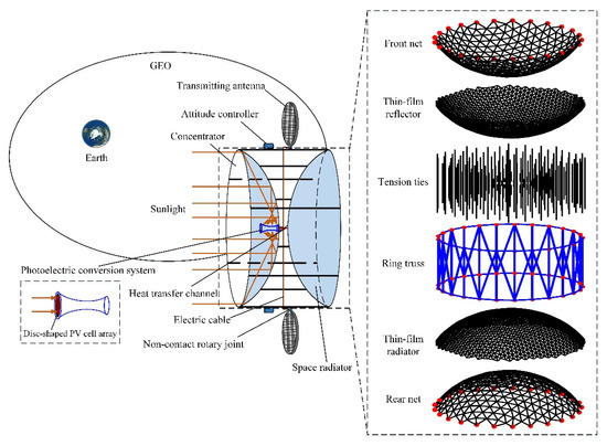
Figure 1.
Diagram of the ring truss-based space solar power station.
The entire system is based on a ring truss deployable structure for its advantages of large aperture, light weight, high packing efficiency, and high accuracy [22,23,24]. Unlike the traditional ring truss reflector antenna [25,26], which only has a metal mesh surface attached to the backside of the front net, a two-layer ring truss structure is proposed in this innovative SSPS design. It mainly consists of a deployable ring truss, tension ties, two cable networks (front net and rear net), and a two-layer thin-film surface. The ring truss is connected to cable networks and supports the cable networks once deployed. Tension ties connect the nodes of the two cable networks and assembly imposes tensile forces between the front net and the rear net to pretension the cable networks structure.
The two-layer thin-film surface is composed of two groups of triangular facets, one group forms the concentrator with a front net, called the top layer, and the other group forms the space radiator with a rear net, called the bottom layer, and both groups are shaped through the pretension of cable networks structure. The triangular facets at the top and bottom layers are made of thin-film materials with high reflectivity and high emissivity, respectively, for solar energy collection and waste heat radiation. The top layer concentrator concentrated several times solar energy on a photoelectric conversion system, which may lead to a serious thermal problem. Therefore, the bottom layer space radiator is used to dissipate the waste heat, transferred from the photoelectric conversion system through the heat transfer channel, to the cold space by heat radiation. The heat transfer channel adopts a multi-functional integrated design to provide support for the photoelectric conversion system while transferring heat out. In addition, the shape of the bottom layer satisfying the thermal control condition can be obtained through a form-finding design based on ensuring the accuracy of the top layer [27,28,29].
During in-orbit operation, the concentrator is tracked to the sun in real-time by an attitude controller distributed on the ring truss. The photoelectric conversion system is fixed together with the concentrator without relative movement. To compensate for the loss of self-blocking, an additional disc-shaped PV cell array is added at the top of the photoelectric conversion system to receive direct incident sunlight. The DC power is transmitted to the transmitting antenna through a non-contact rotary joint, shown in Figure 1, which mainly consists of the fixed plate connected to the ring truss, the rotary track connected with the electric cable, and a pickup system connected to the transmitting antenna. The rotary track transfers the DC to the pickup system through magnetic coupling. The waste heat generated by the photoelectric conversion system is transferred to the space radiator through an efficient heat transfer channel. The aperture of the space radiator shall not exceed that of the concentrator, to ensure that the radiator is always in the shadow of the concentrator and always towards the cold space.
3. Construction Strategy
3.1. Top Layer Concentrator-Based Spherical One-Time Reflection Region
Inspired by the SSPS-OMEGA concept, the spherical one-time reflection region is selected as the concentrator of this concept, and solar energy is collected by the use of the spherical linear concentrating characteristic. The size and shape of the triangular facet in the top layer directly determine the surface accuracy, and also directly affect the energy collection performance of the concentrator. Therefore, the concentrator modular construction strategy is discussed firstly.
3.1.1. Linear Concentrating Characteristic of the Sphere
Figure 2 illustrates the light propagation process under spherical reflection in the XOY coordinate plane. The parametric equation of the spherical surface on the coordinate plane XOY can be expressed as:
where α is the residual angle of the incident angle β.
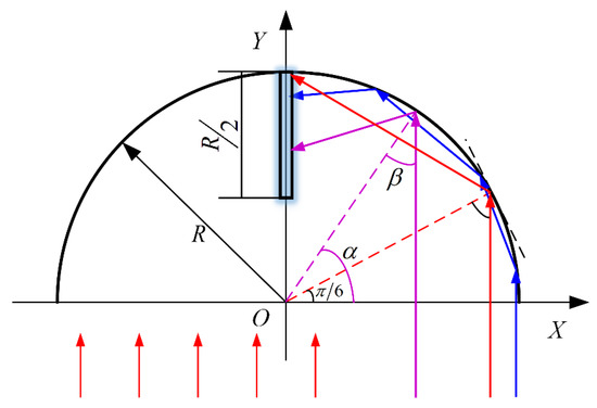
Figure 2.
Light propagation process under spherical reflection.
Based on the Fresnel’s reflection law [30]
where rref and rinc are the unit vectors of the reflected sunlight and incident sunlight, respectively. n is the unit normal vectors of the concentrator.
The equation of reflected sunlight can be derived assuming the parallel incident sunlight can be described as x = Rcos α:
Equation (3) exhibits some concentrating characteristics of spherical concentrator that all incident sunlight will be converged within the region of [R/2, R] of Y-axis, which is described as linear concentrating mode. In addition, when the residual angle of incident sunlight belongs to the interval [π/6, π/2], it will be concentrated on Y-axis after one-time reflection, while the residual angle of incident sunlight belongs to the interval [0, π/6), it will be concentrated on Y-axis after multiple-time reflection. Thus, the region of [π/6, π/2] is named a one-time reflection region.
After multiple reflections, the mathematical description of the light equation becomes quite difficult, which is not conducive to the design of the photoelectric conversion system in the following chapters. At the same time, with the increase in the number of reflections, the incident energy loss is serious, resulting in a decrease in the value of energy collection using this region. Therefore, in this paper, the spherical one-time reflection region is used as the concentrator to collect energy.
Moreover, Equation (3) indicates the reflected sunlight is a line family with a single parameter of residual angle α, so the envelope curve of reflected sunlight could be obtained by establishing the equation
where .
Then, the equation of the envelope curve can be derived as:
Equation (5) shows another important concentrating characteristic that all incident sunlight will be reflected between the envelope curve and spherical parametric curve. It is significant for the construction of the photoelectric conversion system with high solar energy collection performance.
3.1.2. Spherical Concentrator Modularity
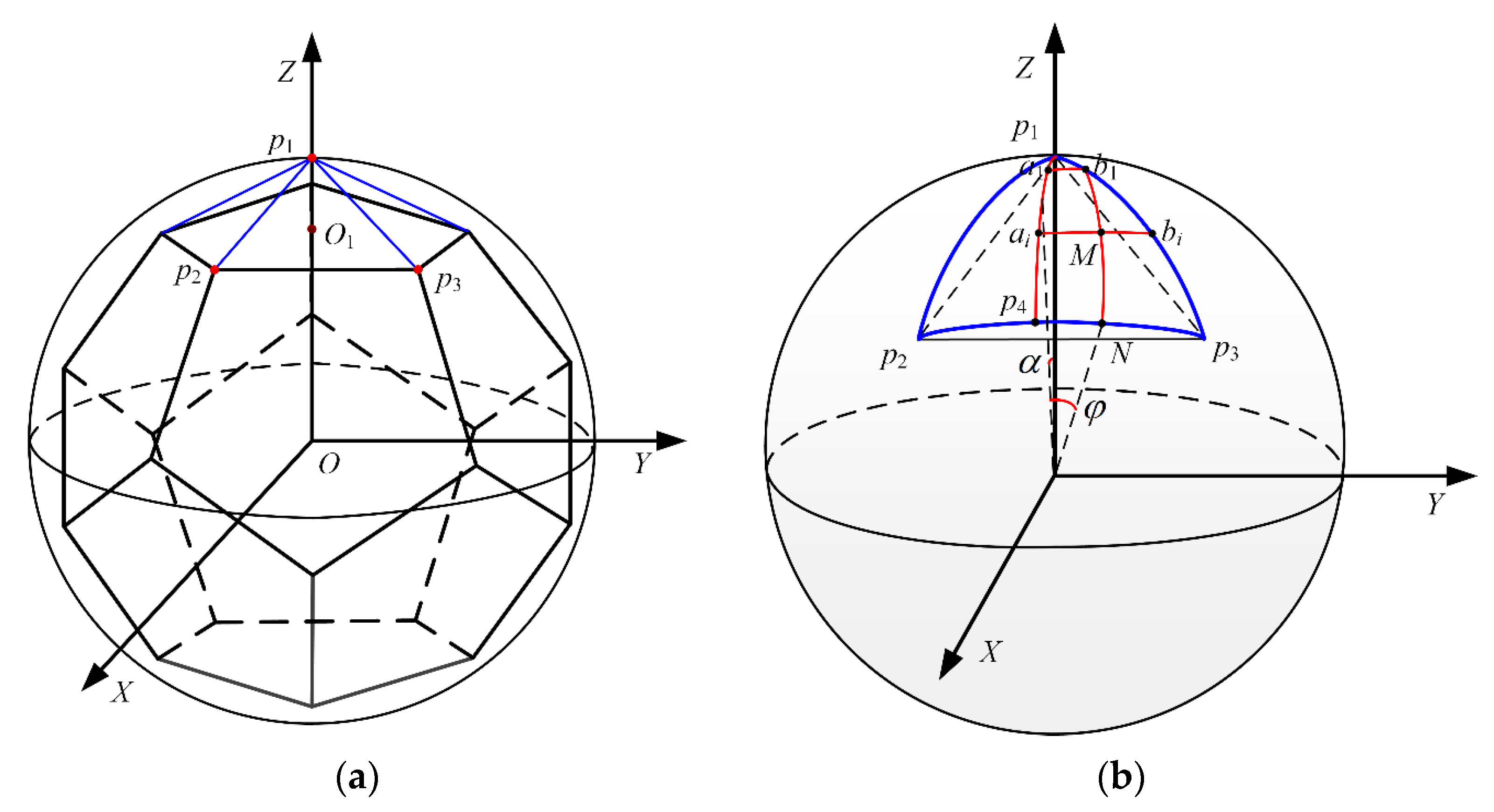
Compared with the equal latitude and longitude grid division, the spherical polygonal grid division has the advantages of better isometric property and structural stability [31]. Therefore, the spherical one-time reflection concentrator of this SSPS concept is constructed by spherical polygonal grid division, and the regular dodecahedron is used to generate a spherical grid.
As shown in Figure 3a, the center O1 of a regular pentagon surface in the regular dodecahedron is firstly obtained, and the straight line OO1 is made and intersects the sphere at point p1, connecting p1 with other vertices of the regular pentagon to form five isosceles triangles, as shown in Figure 3a. Then, the triangle is projected to the sphere with radius length Op1 to form spherical isosceles triangles, as shown in Figure 3b. All three sides of the spherical triangle are geodesic arcs. In this way, the spherical triangle grid can be divided first, and then the coordinate of the entire spherical grid can be obtained by rotation and symmetry operation on the basis of the coordinate of the spherical triangle grid.
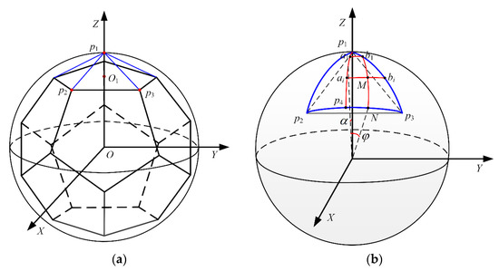
Figure 3.
Spherical polygonal grid division: (a) the regular dodecahedron; (b) spherical triangle mapping.
As shown in Figure 3b, in order to further simplify the calculation procedure, is placed symmetrically on both sides of coordinate plane XOZ, and the coordinates of grid points of the spherical triangle can be obtained by mirror mapping the coordinates of grid points of about plane XOZ.
Firstly, the arc is evenly divided into nc equal parts (nc is the number of modular layers), and the arc is evenly divided into nc equal parts by a set of declination circles passing through the point ai, and each partition point is denoted as bi. Then, meridian circles are set through bi, intersecting the arc at point N, and intersecting the arc at point M. By calculating the azimuth α and elevation β corresponding to point M, the coordinates of M can be obtained, thus the coordinates of grid points in a spherical triangle can be obtained by traversing nc equally divided intersections. Finally, the triangular facets are constructed by connecting adjacent points.
According to the radius of the sphere and the corresponding azimuth and elevation, the coordinates of the grid points in the spherical triangle can be expressed as:
Finally, the modular division of the spherical triangle is shown in Figure 4a. Retaining the one-time reflection region of the spherical grid, the modularity of the top layer concentrator is obtained, as shown in Figure 4b.
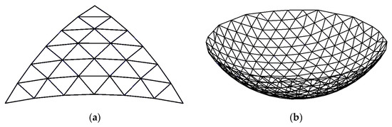
Figure 4.
Diagram of spherical concentrator modularity (R = 0.5 m, nc = 6): (a) Spherical triangle; (b) Top layer concentrator.
3.2. Bottom Layer Space Radiator
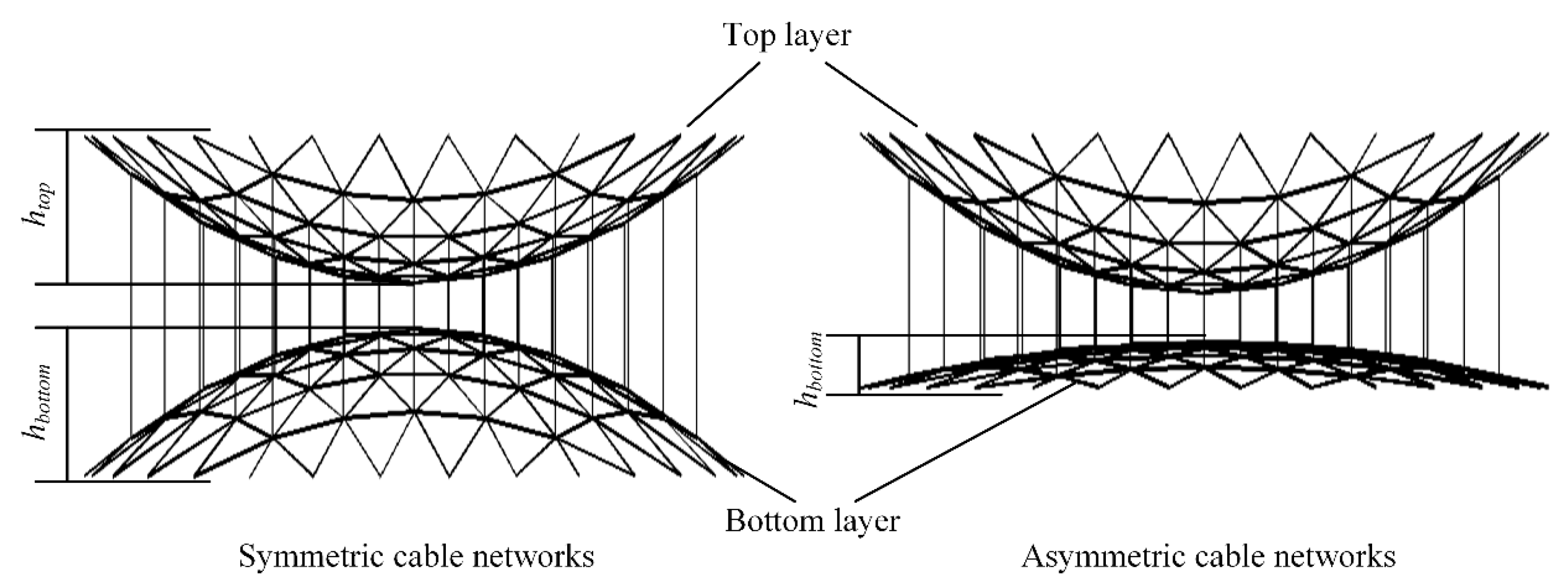
After the construction of the top layer, the bottom layer space radiator could be constructed using symmetric or asymmetric cable networks [29], as shown in Figure 5. The grid of the bottom layer is consistent with the top layer, and the grid points are one to one.
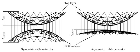
Figure 5.
Symmetric or asymmetric cable networks.
For the symmetric cable networks, the height of the bottom layer is equal to the top layer, and the height of the ring truss after deployment is at least twice as high as the bottom layer. As for asymmetric cable networks, the height of the bottom layer can be optimized and adjusted without changing the height and surface accuracy of the top layer. So the area of the space radiator is maximum when using symmetric cable networks, which can be expressed as
where hbottom is the height of the bottom layer.
When using asymmetric cable networks, the area of the space radiator can be expressed as
The area of the space radiator depends on the thermal load of the photoelectric conversion system, which can be expressed as [32]
where σ is the Stefan-Boltzmann constant, 5.67 × 10⁻⁸ W/(m2·K4), ε is the emissivity. Xsr is the angle factor of the concave of the bottom layer toward space. Tsr is the average temperature of the space radiator, T∞ is the environment temperature, 4 K.
When operating in orbit, the heat load can be estimated
where I0 is the solar constant, and I0 = 1367 W/m2 in geostationary earth orbit (GEO). Aaper is the area of aperture of the concentrator. ηc is the collection efficiency of the concentrator. αpv and ηpv are absorptivity and efficiency of PV cell array, respectively.
3.3. Configuration of the Photoelectric Conversion System
3.3.1. Generatrix Description
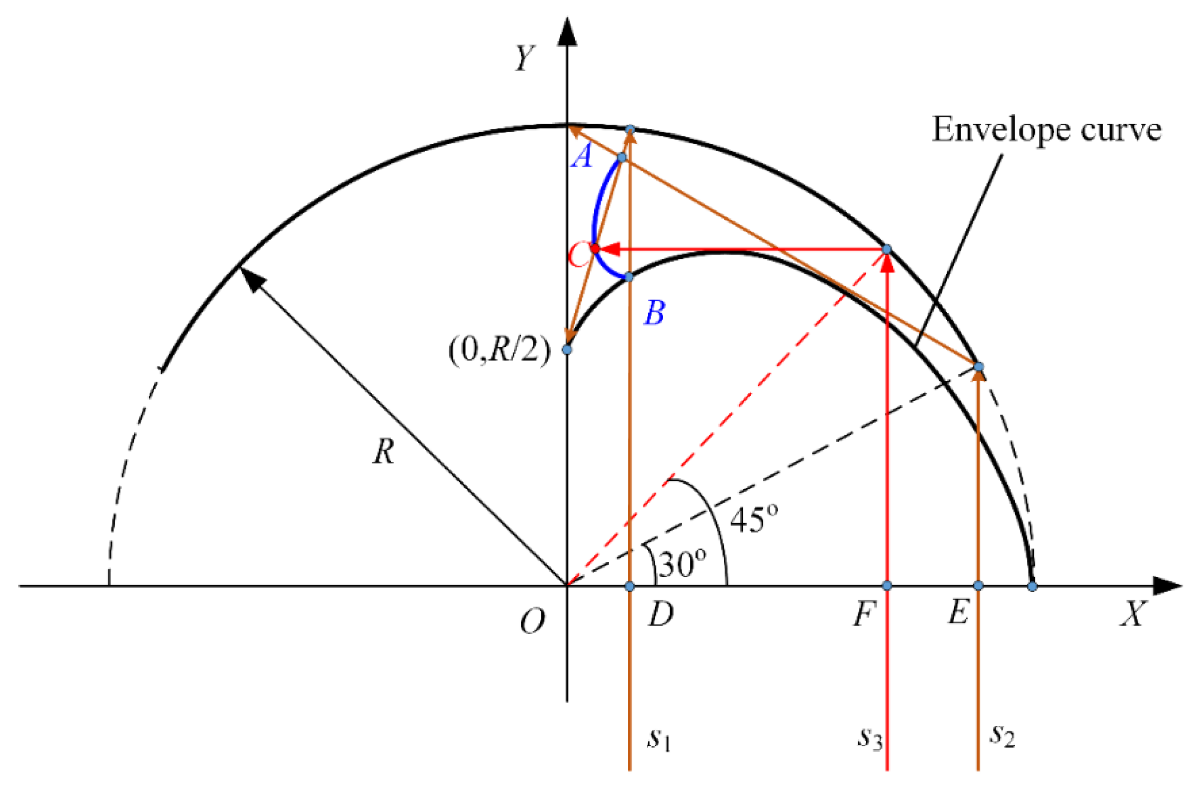
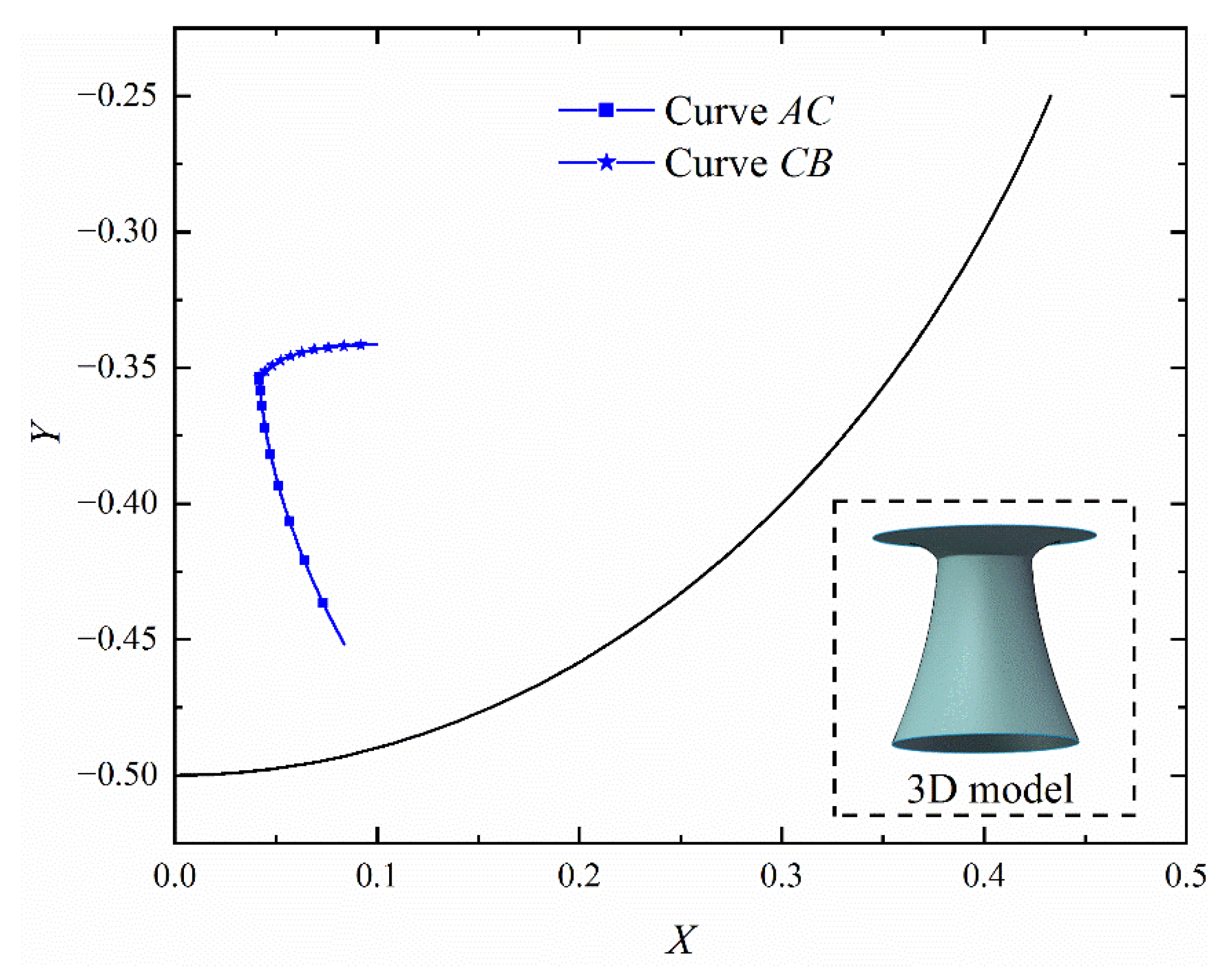
An ideal spherical concentrator with a one-time reflection region is used to design the configuration of the photoelectric conversion system, and a coordinate system for the generatrix of the photoelectric conversion system in a two-dimensional plane is illustrated in Figure 6, where the envelope curve is contained. According to Equation (5), the envelope curve will intersect the Y-axis at (0, R/2). The curve AB represents the generatrix of the photoelectric conversion system. To ensure more solar energy is received, the setting of endpoint A and endpoint B is critical.

Figure 6.
Illustration of the generatrix of the photoelectric conversion system.
Suppose an incident ray s1 intersecting the X-axis at point D intersects the envelope curve at point B, then all incident sunlight from the OD region will be blocked, so the abscissa value of point B determines the self-blocking by the photoelectric conversion system. Another incident light s2 at the edge of the concentrator with an incident angle of π/3 will intersect the Y-axis at point (0, R), and its reflection intersects the reflection of s1 at A point. As known from the concentrating characteristic of the concentrator, all incident sunlight from the DE region will be concentrated on the curve AB.
Furthermore, to ensure a more uniform energy distribution, point C is selected to carry out a two-segment design for the generatrix. An incident sunlight s3 intersecting the X-axis at point F with incident angel π/4 is selected out for its reflected light is a horizontal line, which is conducive to find out the intersection. The reflection of s3 intersects the reflection of s1 at point C, and all incoming energy from DF and FE regions will be concentrated on curves AC and CB, respectively. The energy density on the curve CB is obviously higher than that on the curve AC, so it is necessary to perform a two-segment design for curve AB.
Considering the convenience of the design, the Bézier curve based on the Bézier polynomial parametrization is introduced. Bézier curve is a parameterized curve controlled by control points with good continuity, conductibility, convex hull property, and endpoint property, which is very convenient for generatrix design [33]. A Bézier curve of order n can be defined as:
where is Bernstein polynomial, Pi is the control point.
Additionally, the derivative of any point on the Bézier curve can be expressed as
3.3.2. Optimization Design
In order to design the generatrix of the photoelectric conversion system based on energy collection and distribution, the Monte Carlo ray-tracing method (MCRT) is adopted [21]. By using the MCRT method, the position and direction of each sunlight considering sunlight cone angel could be described as
where Rr, Rθ, Rγ, and Rβ are probability distributions of radius rc, incident angel θc, conical angle γ, and circumferential angle β, respectively, which are independent and evenly distributed in the interval [0, 1]. Rc is the radius of the concentrator aperture, and αmax is the maximum cone angle.
Assuming that the sunlight incident from the plane y equals R, the parameter equation of incident sunlight can be established as
Additionally, the energy carried by single sunlight can be defined as
where Ns is the number of sampled sunlight that irradiates to the aperture.
Then, the energy collected by the photoelectric conversion system can be expressed as
where Np represents the vector of the segmented numbers of curves AC and CB, E represents the vector of energy collected by curves AC and CB. Ns,j is the number of sunlight falling on the jth subsection. φ(θ) represents the angular response of photovoltaic cell at incident angle θ, which is considered as
where θm is the maximum responsible angle vector and is set to be 4π/9 in this paper.
Then, the energy distribution can be expressed as
where I is the unit vector, and
The photoelectric conversion system is expected to receive energy as much as possible, and the energy distribution is as uniform as possible. Thus, the objective function can be expressed as
Then, the mathematical optimization model can be established as
where P (P0, P1, …, Pn) = [x1, x2, …, xn; y1, y2, …, yn]T, ω1 and ω2 are weighting factors for energy collection and distribution, respectively. The first two constraint functions indicate that curves AC and CB satisfy geometric continuity and derivative continuity at point C. ηs is the self-blocking of the photoelectric conversion system, and [ηs] is a pre-given value. U is the feasible region of the coordinates of the control points.
3.3.3. Optimization Results
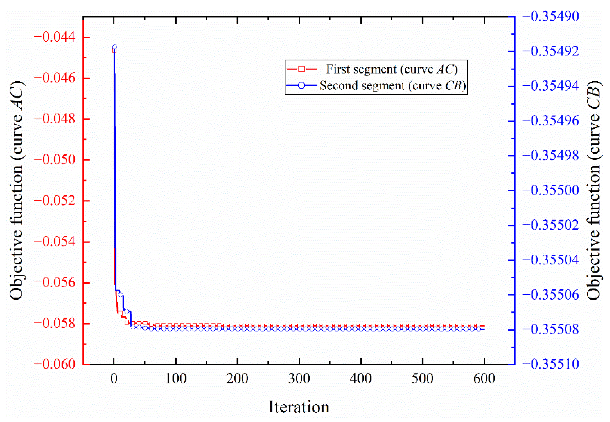
In order to avoid the impact of the initial value on the optimization procedure and the difficulties caused by the sensitivity solution, Particle Swarm Optimization (PSO) is used to obtain an optimal solution based on the mathematical optimization model established above. To reduce the calculation scale, a concentrator model with R equal to 0.5 m is used for the optimization procedure. Generations are set to 600 and the size of the population is set to 20. The order of curves CB and AC are 2 and 3, respectively, and the number of subsections of curves CB and AC is 3 and 6, respectively. The number of sampled sunlight is set to 105 after sensitivity analysis. The pre-given value [ηs] is set to 0.05, and the weighting factors are set to ω1 = ω2 = 0.5.
Then, the iterative convergence curve of the objective function is shown in Figure 7, and the optimal generatrix of the photoelectric conversion system and its 3D model are illustrated in Figure 8, the energy distribution is shown in Figure 9, and detailed parameters are listed in Table 1.

Figure 7.
Iteration curve of the objective function for two-segment design.

Figure 8.
The optimal generatrix of the photoelectric conversion system.

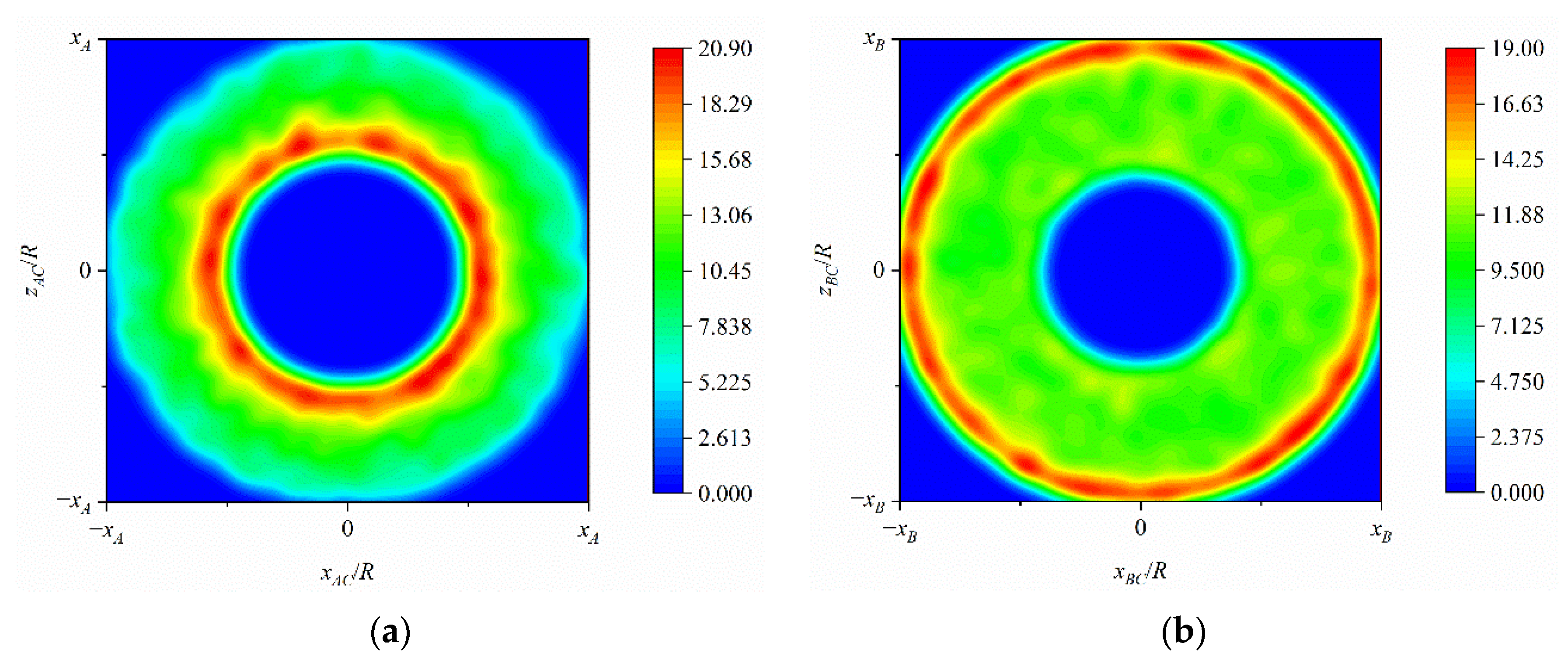
Figure 9.
Energy distribution on photoelectric conversion system: (a) the first segment (curve AC); (b) the second segment (curve CB).

Table 1.
Detailed parameters of optimal design.
As seen in Table 1, the designed photoelectric conversion system exhibits an excellent energy collection performance with 100% solar energy collection; meanwhile, the well-performed energy distribution is also obtained in both segments. The incident angle of reflected on the photovoltaic cell array is as low as 0.01°, and the maximum does not exceed 78°, which fully meets the design requirements. The coordinates of the control point are also listed.
3.4. Microwave Transmitting Antenna
After the DC power is transmitted to the transmitting antenna, the energy received by the rectenna on the ground depends on the beam collection efficiency (BCE) between the transmitting antenna and rectenna, which can be obtained according to the radio wave theory [34]
where Pr and Pt are transmitted power by transmitting antenna and received power by rectenna, respectively. At, Ar and λ are the aperture area of the transmitting antenna, aperture area of the rectenna, and wave length, respectively. L is the distance between two antennas, which should be satisfied the Fresnel region condition to ensure efficient transmission [35].
where Dt is the diameter of the transmitting antenna.
Moreover, carefully considering atmospheric attenuation, the microwave frequency of 5.8 GHz is chosen in this concept for it is within the microwave radio windows of the atmosphere. The efficiency of microwave transmission keeps high at this frequency even in bad weather.
Furthermore, the size of the transmitting antenna could be quite large when the SSPS is working in orbit, so a step amplitude taper to reduce the manufacturing difficulty and complexity with little loss of efficiency is adopted for facilitating modular manufacturing and assembly. For the stepped taper, the whole transmitting antenna is divided into several rings, and identical amplifiers are used in the same ring, and more details could be seen in our previous work [36].
4. Performance Analysis
4.1. Modularization Theory Error of Concentrator
The concentrator-based spherical one-time reflection region is modularly constructed with a series of triangular facets, so there must be a theoretical error, which reflects the surface accuracy of facets approaching the sphere.
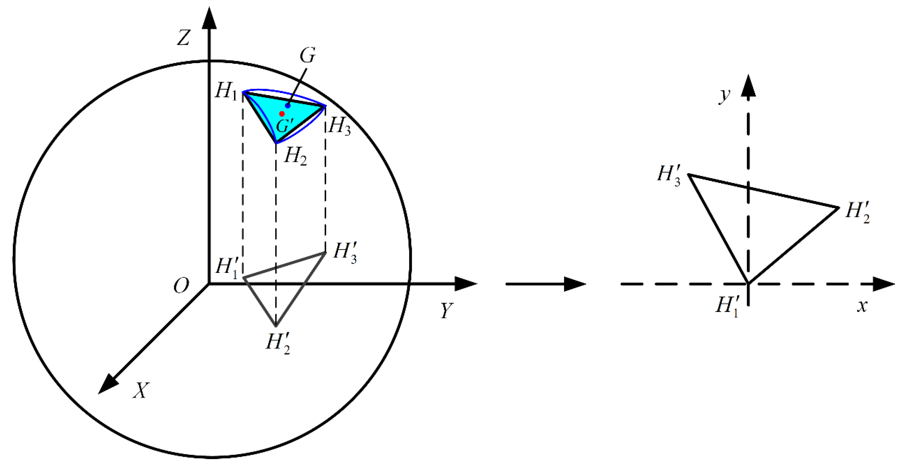
As shown in Figure 10, ΔH1H2H3 is any divided triangular facet, and its projection onto XOY plane is also illustrated. Point G is any point on the spherical triangular surface.

Figure 10.
Schematic diagram of theoretical error description.
Suppose the equation of the triangular ΔH1H2H3 plane is expressed as , then the parameters a, b, and c can be obtained from the coordinates of the vertices H1, H2, and H3. Moreover, the equation of the normal line passing point G can be expressed as
Then, the coordinates of the intersection G’ of the normal line with the triangular ΔH1H2H3 plane can be obtained, and the distance between points G and G’ is
Thus, the modularization theory error of the concentrator can be obtained by
where NUM is the number of triangular facets, and
where , and are slopes of lines , and , respectively. , and are the intercepts of lines , and , respectively. , and are abscissas of points H1, H2, and H3, respectively.
Based on Equations (27)–(30), the modularization theory errors and maximum side lengths of the concentrator with radius R equal to 0.5 m at different division layers are listed in Table 2.
Table 2.
The values of theory error and maximum side length.
It can be seen that with the increase of the number of division layers, the theoretical error and the maximum side length decrease correspondingly, indicating more triangular facets are divided and a more accurate surface approximation is obtained. Referring to the design requirements for theoretical errors of cable-mesh reflector antennas [22], which is usually less than 1 mm. Therefore, the concentrator with modular division layers of 6 is selected as the subsequent analysis model.
4.2. Solar Energy Collection and Distribution
4.2.1. Modularization
After modularization, the concentrator changes from an ideal sphere to a series of triangular facets, which may result in energy loss as shown in Figure 11, as well as change in energy distribution. It may not achieve well-performed energy collection and energy distribution as listed in Table 1.
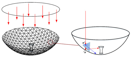
Figure 11.
Energy collection and distribution deviation after modularization.
When analyzing the energy collection and distribution after spherical modularization, the unit normal vector n of point G in Equation (2) will no longer be (xG/R, yG/R, zG/R), and changes
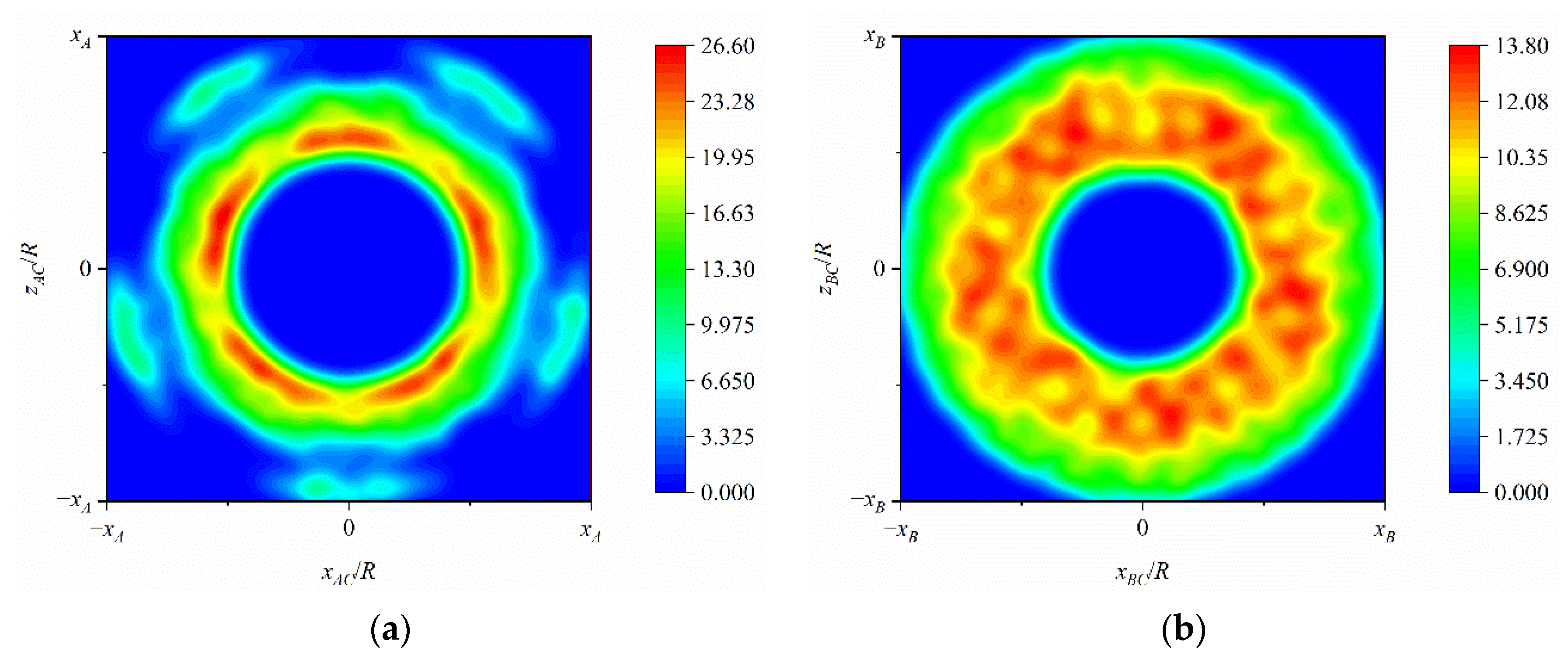
By using the MCRT method and the same number of sampled sunlight in Section 3.3, the energy distribution of the photoelectric conversion system is shown in Figure 12, and the detailed values of energy collection and distribution are listed in Table 3.

Figure 12.
Energy distribution after modularization: (a) the first segment (curve AC); (b) the second segment (curve CB).
Table 3.
Detailed values of energy collection and distribution.
A comparative analysis of the data in Table 1 and Table 3 shows that the energy collection drops from 100% to 82% with a loss of 18% after modularization, including 2% for the first segment and 16% for the second segment. The loss of the second segment is much larger than that of the first segment. In addition, modularization improves the energy distribution of the second segment, while making it worse of the first segment.
4.2.2. Tracking Accuracy
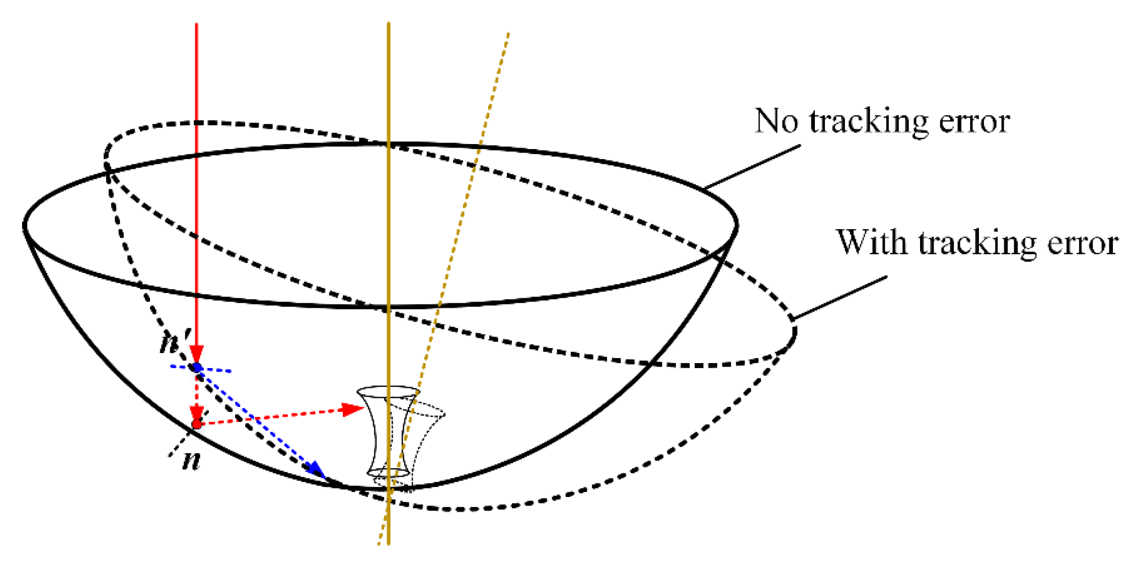
The two-layer ring truss-based SSPS is oriented toward the sun through the electric propulsion distributed on the ring truss, and the tracking accuracy is another important factor affecting the performance of energy collection and distribution, as shown in Figure 13.
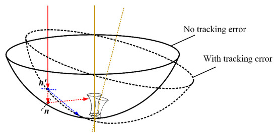
Figure 13.
Energy collection and distribution deviation with tracking error.
When there exists a tracking error, the unit vector of incident sunlight in Equation (16) changes
where δte is the vector of tracking error, which can be expressed as
where θx and θz are tracking angel deviations, respectively.
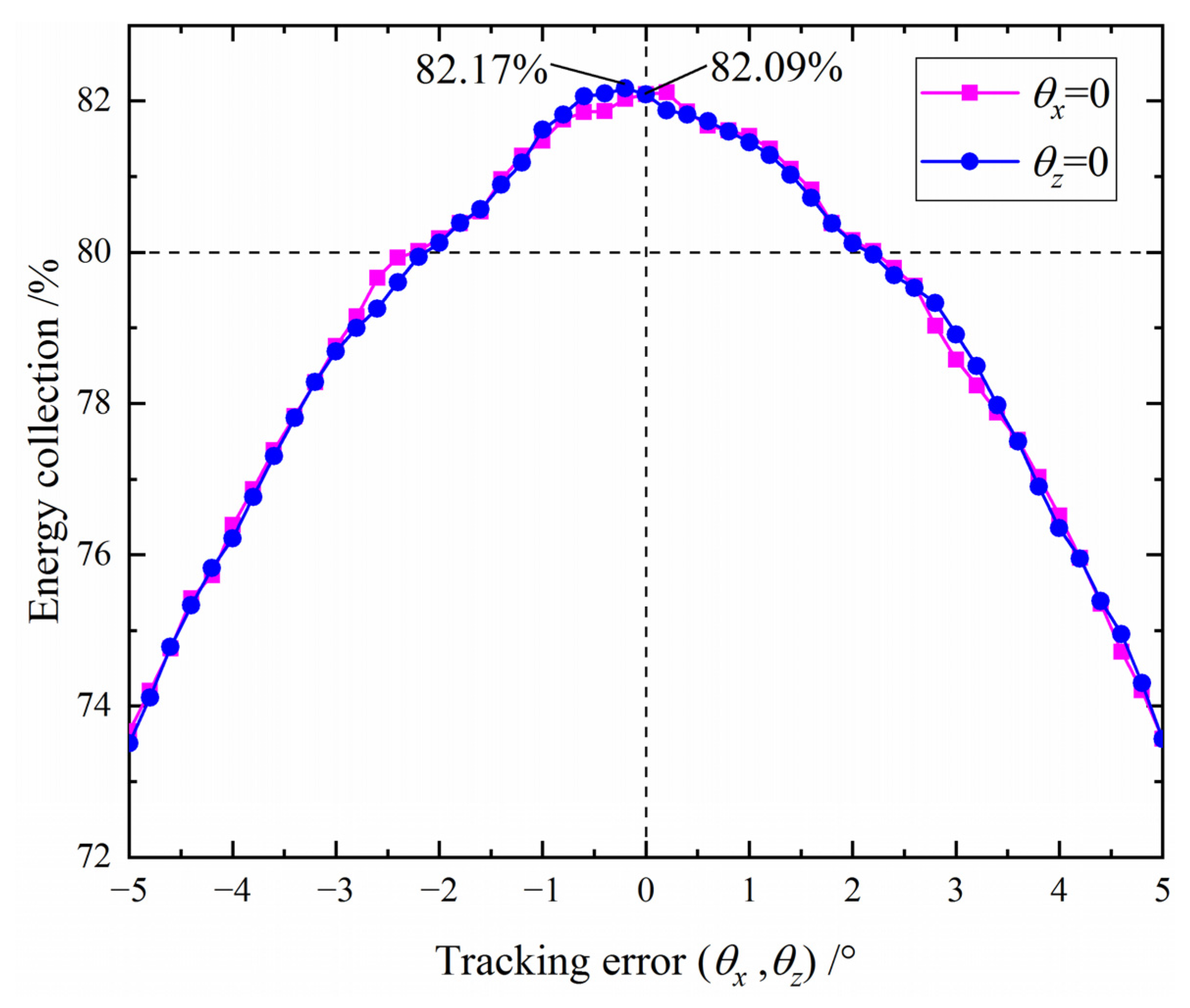
Figure 14 illustrates the energy collection of the photoelectric conversion system with different tracking errors. Figure 15 shows the variation curves of energy collection and distribution of different segments with tracking error.
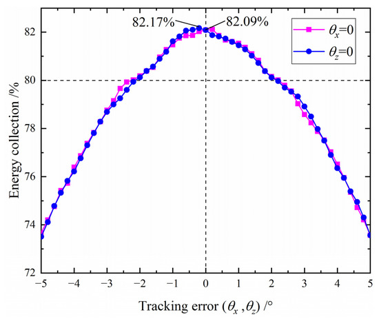
Figure 14.
The total energy collection with different tracking errors.
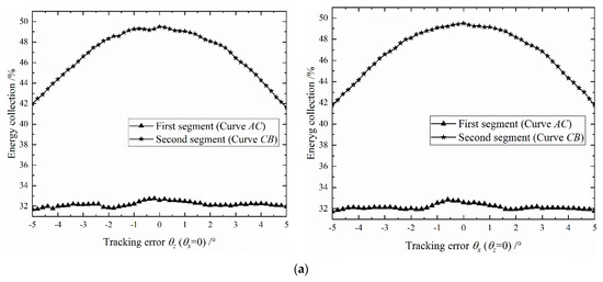
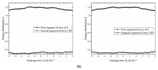
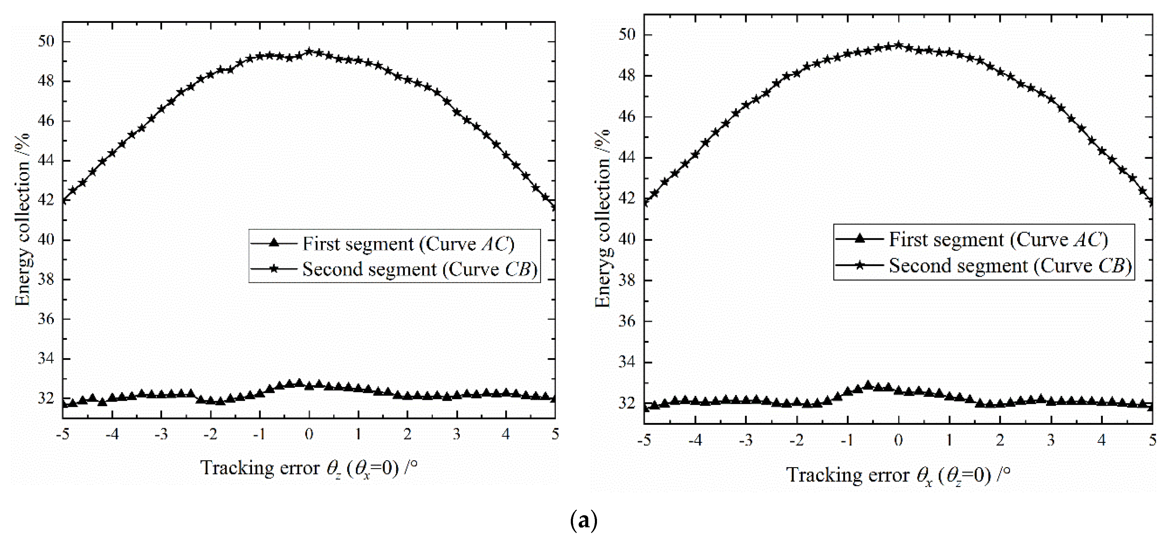
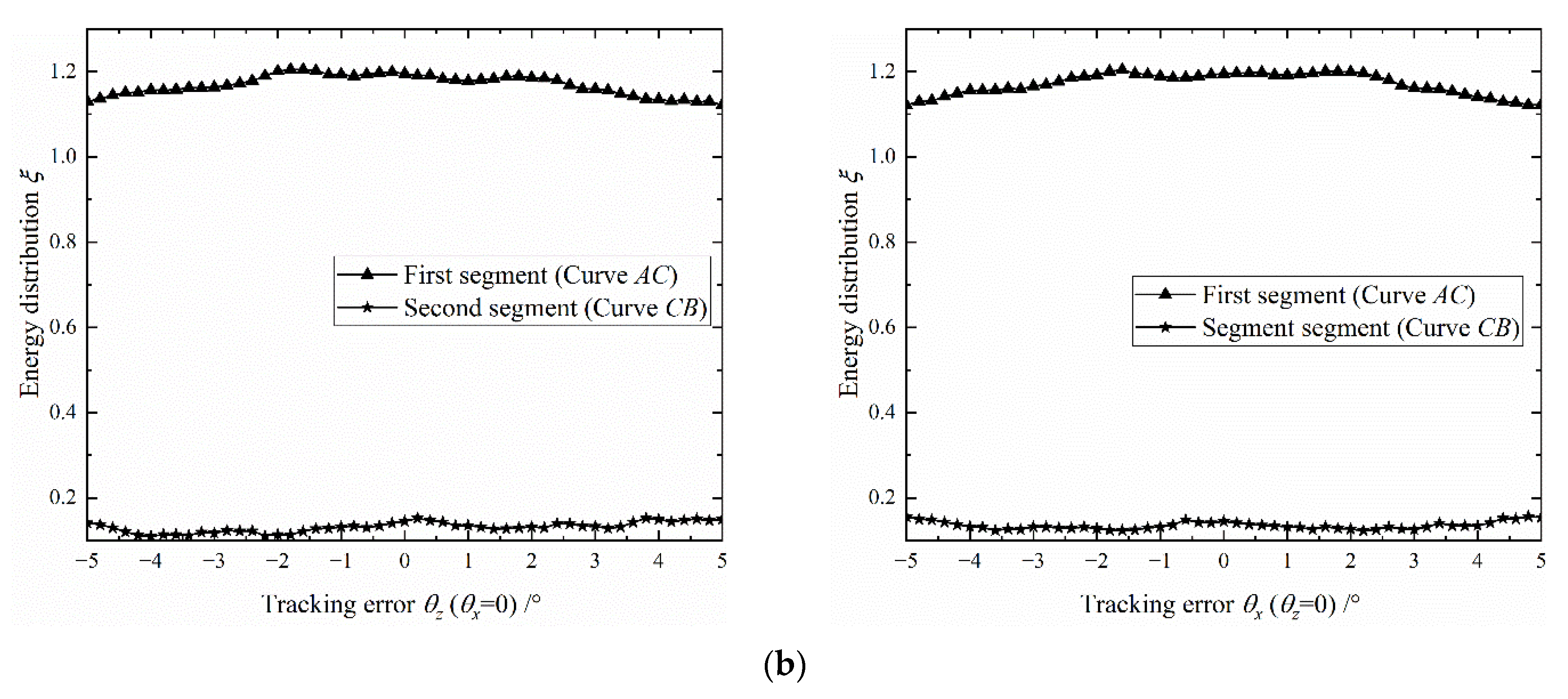
Figure 15.
Energy collection and distribution of different segments: (a) Energy collection; (b) Energy distribution.
As shown in Figure 14, due to modularity, energy collection does not change the same in both directions (θx = 0 and θz = 0), but it shows a consistent trend, that is, the energy collection decreases with the increase of the tracking error. When the tracking error is less than 2°, the energy collection of the concentrator is greater than 80%. When the tracking error is more than 5°, the energy collection is less than 74%. As seen in Figure 15, the tracking error has a greater effect on the energy collection of the second segment and a little effect on that of the second segment in both directions. However, the increase in tracking error does not result in a dramatic change in the energy distribution in both segments and directions, and even for the first segment, the energy distribution tends to get better with the increase in tracking error.
4.3. Orbital Thermal Characteristics
After completing the above system construction and energy performance analysis, the orbital thermal analysis of the system is carried out to obtain the temperature distribution of the system and evaluate the thermal control performance of the bottom layer space radiator on the photoelectric conversion system.
A 3D thermal analysis model is established with the finite-element method software FEMAP, as shown in Figure 16a, and the thermo-physical properties of this model are listed in Table 4. The heat transfer channel, like the rear net, is made of graphene materials with high heat conductivity [37], and its configuration is shown in Figure 16b. The ring truss and tension ties mainly play a supporting role and have little effect on temperature, so they are ignored in this model. In addition, the transmitting antenna can be thought of as a separate subsystem, with only electrical connections to other components and few thermal connections, so it is also not considered in this thermal analysis model. In order to preliminarily analyze the thermal characteristics of the proposed system in orbit, the bottom layer space radiator adopts symmetric cable networks structure and no tracking error for the whole system.
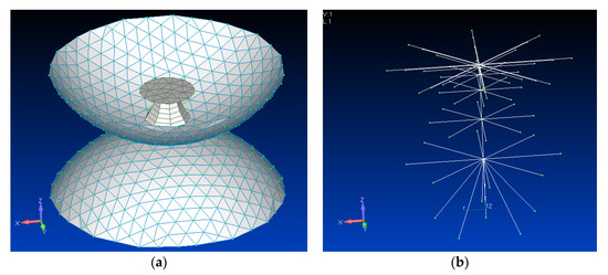
Figure 16.
Model of orbital thermal analysis: (a) the whole system; (b) the heat transfer channel.
Table 4.
Thermo-physical properties of the model.
The main device of the photoelectric conversion system is a thin-film gallium arsenide (GaAs) PV cell with a conversion efficiency of 40% [38]. Then, the temperature distribution of the two-layer ring truss-based SSPS is shown in Figure 17.
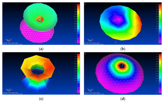
Figure 17.
Temperature distribution of two-layer ring truss-based SSPS in orbit: (a) the whole system; (b) the disc-shaped PV cell array; (c) photoelectric conversion system; (d) bottom layer space radiator.
Clearly seen in Figure 17a, the maximum temperature is around 130 °C and located on the photoelectric conversion system, in detail, on the second segment. Although the disc-shaped PV cell array only receives direct sunlight, it is affected by the radiative heat transfer of the photoelectric conversion system, making its average temperature reaches 123 °C, as shown in Figure 17b. The temperature of the photoelectric conversion system, as shown in Figure 17c, performs well below 130 °C and shows a temperature distribution of higher temperature on the second segment and lower temperature on the first segment, partly because of the higher energy collection and partly because of the longer distance from the space radiator. Figure 17d shows a good temperature distribution of the bottom layer space radiator with the difference between the maximum and minimum temperature being approximately 7 °C.
The results indicate that the bottom layer radiator exhibits excellent thermal control performance, and can effectively control the temperature of the photoelectric conversion system and ensure that it works within a reasonable temperature range. It should also be noted that the difference between the temperature of the photoelectric conversion system and the temperature of the bottom layer space radiator is still quite large, indicating that a more efficient heat transfer channel is urgently needed and critical for achieving better thermal control.
5. System Parameter Estimation
Table 5 provides the preliminary efficiencies and power level for the proposed SSPS. The system parameters of the 2 GW-level two-layer ring truss-based SSPS are summarized in Table 6, with a preliminarily estimated weight listed in Table 7. It must be noted that the proposed SSPS may be built around 2050 and the parameters are estimated based on future advances in relevant science and technology.
Table 5.
Preliminarily efficiencies and power level for proposed SSPS.
Table 6.
The system parameters of the 2 GW-level two-layer ring truss-based SSPS.
Table 7.
Preliminary system weight estimation.
6. Conclusions
A two-layer ring truss-based SSPS is proposed and investigated in this paper at a conceptual study level. This concept has some advantages, which are summarized below.
- High energy collection efficiencyFor the ideal concentrator, a perfect 100% energy collection can be achieved. For the modular division layers of 6 and the tracking error of no more than 2°, 80% energy collection is guaranteed.
- Good energy distributionFor the ideal concentrator, the indexes of energy distribution on two segments of the photoelectric conversion system are only 0.878 and 0.291, respectively. For the modular division layers of 6, their values are 1.195 and 0.145, respectively.
- Low system massCompared with existed SSPS concept [10,11,12,13], lower system mass is achieved, which means a higher power mass ratio.
- Well-performing thermal controlWith the bottom layer space radiator, the temperature of the photoelectric conversion system can be effectively controlled l below 130 °C.
However, it must be realized that the current research remains at the initial conceptual stage, many problems still need to be investigated in future work, such as:
- Ultra-large structure space deploymentThe entire system is based on a ring truss deployable structure, which can be directly deployed for an MW-level SSPS. However, it is still difficult for a GW-level SSPS, which needs to be studied deeply.
- High precision attitude control.
- The effects of ecliptic angle.
Author Contributions
Conceptualization, G.F.; methodology, G.F.; software, G.F.; validation, G.F., X.J. and Y.Y.; formal analysis, Y.Z.; investigation, Y.Y.; resources, X.J.; data curation, G.F.; writing—original draft preparation, G.F.; writing—review and editing, G.F. and Y.Z.; visualization, G.F.; supervision, Y.Z.; project administration, G.F. and Y.Y.; funding acquisition, Y.Z. All authors have read and agreed to the published version of the manuscript.
Funding
This work was supported by the National Key R&D Program of China (No. 2021YFB3900300), the National Natural Science Foundation of China (Nos. 52022075 & U1937202), Natural Science Basic Research Program of Shaanxi (No.2021JCW-05).
Data Availability Statement
Not applicable.
Conflicts of Interest
The authors declare no conflict of interest.
Nomenclature
| R | spherical concentrator radius (m) |
| rref, rinc | the unit direction vector |
| n | the unit normal vectors |
| F | the reflected ray equation |
| nc | the number of modular layers |
| Sr | the area of space radiator |
| hbottom | the height of bottom layer |
| Xsr | the angle factor |
| Tsr | the average temperature of space radiator |
| T∞ | the environment temperature |
| I0 | solar constant |
| Aaper | the area of aperture of the concentrator |
| n | the order of Bézier curve |
| C(u) | parametric equation |
| Bi,n(u) | Bernstein polynomial |
| P | control point |
| C’(u) | the derivative of C(u) |
| rc | radius of incident sunlight |
| Rc | radius of concentrator aperture |
| Rr, Rθ, Rγ and Rβ | probability distributions |
| e | the energy carried by a single sunlight |
| Ns | the number of sampled sunlight |
| E | the energy collected by photoelectric conversion system |
| Np | the segmented numbers |
| Ns,j | the number of sunlight falling on the jth subsection |
| I | unit vector |
| Ed,j | the energy collected by the jth subsection |
| the average of energy collection | |
| U | the feasible region |
| Pr | transmitted power by transmitting antenna |
| Pt | received power by rectenna |
| At, Ar | aperture area |
| λ | wave length |
| L | distance between two antennas |
| Dt | the diameter of the transmitting antenna |
| Greek symbols | |
| α | the residual angle |
| β | the incident angle |
| , | elevation and azimuth |
| σ | Stefan-Boltzmann constant |
| ε | emissivity |
| ηc | collection efficiency of the concentrator |
| αpv, ηpv | absorptivity and efficiency of PV cell array |
| φ(θ) | angular response of photovoltaic cell |
| ξ | energy distribution index |
| θc | incident angel of single sunlight |
| γ | conical angle |
| β | circumferential angle |
| ω1, ω2 | weighting factors |
| Φ | objective function |
| ηs | self-blocking of photoelectric conversion system |
| [ηs] | pre-given value of ηs |
| θm | the maximum responsible angle |
| δ | theory error |
| δte | tracking error |
| θx, θz | tracking angel deviations |
| Abbreviations | |
| SSPS | space solar power station |
| ISC | integrated symmetrical concentrator |
| ALPHA | arbitrarily large phased array |
| OMEGA | Orb-shape Membrane energy gathering array |
| ENZ | ε-near-zero |
| PV | photovoltaic |
| GEO | geostationary earth orbit |
| MCRT | Monte Carlo ray tracing method |
| PSO | Particle Swarm optimization |
| BCE | beam collection efficiency |
| GaAs | gallium arsenide |
References
- Duan, B.Y. The main aspects of the theory and key technologies about Space Solar Power Satellite. Sci. Sin. Tech. 2018, 48, 1207–1218. (In Chinese) [Google Scholar] [CrossRef]
- Zhang, T.; Li, Y.T.; Chen, Y.; Feng, X.Y.; Zhu, X.Y.; Chen, Z.; Yao, J.; Zheng, Y.; Cai, J.; Song, H.; et al. Review on space energy. Appl. Energy 2021, 292, 116896. [Google Scholar] [CrossRef]
- Glaser, P.E. Power from the sun: Its future. Science 1968, 162, 857–861. [Google Scholar] [CrossRef]
- DOE/NASA. Program Assessment Report Statement of Finding—Satellite Power Systems; Concept Development and Evaluation Program DOE/ER-0085; NASA: Washington, DC, USA, 1980.
- Sasaki, S.; Tanaka, K.; Higuchi, K.; Okuizumi, N.; Kawasaki, S.; Shinohara, N.; Senda, K.; Ishimura, K. A new concept of solar power satellite: Tethered-SPS. Acta Astronaut. 2006, 60, 153–165. [Google Scholar] [CrossRef]
- Seboldt, W.; Klimke, M.; Leipold, M.; Hanowski, N. European Sail tower SPS concept. Acta Astronaut. 2001, 48, 785–792. [Google Scholar] [CrossRef]
- Hou, X.B.; Wang, L.; Zhang, X.H.; Zhou, L. Concept design on multi-rotary joints SPS. J. Astronaut. 2015, 36, 1332–1338. [Google Scholar]
- Carrington, C.; Fikes, J.; Gerry, M.; Perkinson, D.; Feingold, H.; Olds, J. The abacus/reflector and integrated symmetrical concentrator: Concepts for space solar power collection and transmission. In Proceedings of the 35th Intersociety Energy Conversion Engineering Conference, Las Vegas, NV, USA, 24–28 July 2000. [Google Scholar]
- Mankins, J.C. A technical overview of the “suntower” solar power satellite concept. Acta Astronaut. 2002, 50, 369–377. [Google Scholar] [CrossRef]
- Mankins, J.C. The Case for Space Solar Power; Virginia Edition Publishing: Houston, TX, USA, 2014; pp. 19–21. [Google Scholar]
- Yang, Y.; Zhang, Y.Q.; Duan, B.Y.; Wang, D.X.; Li, X. A novel design project for space solar power station. Acta Astronaut. 2016, 121, 51–58. [Google Scholar] [CrossRef]
- Li, X.; Duan, B.Y.; Song, L.W.; Yang, Y.; Zhang, Y.Q.; Wang, D.X. A new concept of space solar power satellite. Acta Astronaut. 2017, 136, 182–189. [Google Scholar] [CrossRef]
- Li, X.L.; Fan, G.H.; Zhang, Y.Q.; Ji, X.F.; Li, M. A fresnel concentrator with fiber-optic bundle based space solar power satellite design. Acta Astronaut. 2018, 153, 122–129. [Google Scholar] [CrossRef]
- Fan, G.H.; Duan, B.Y.; Zhang, Y.Q.; Yang, Y.; Ji, X.F.; Li, X.L. Secondary concentrator design of an updated space solar power satellite with a spherical concentrator. Sol. Energy 2021, 214, 400–408. [Google Scholar] [CrossRef]
- Jaffe, P.; Hodkin, J.; Harrington, F.; Person, C.; Nurnberger, M.; Nguyen, B.; LaCava, S.; Scheiman, D.; Stewart, G.; Han, A.; et al. Sandwich module prototype progress for space solar power. Acta Astronaut. 2014, 94, 662–671. [Google Scholar] [CrossRef]
- Yang, C.; Hou, X.B. Iterative two-layer thermal design strategy for step sandwich antenna of space solar power satellite using modified constrained multi-objective optimization. Aerosp. Sci. Technol. 2021, 118, 106987. [Google Scholar] [CrossRef]
- Yang, C.; Hou, X.B.; Chang, S.N. A synchronous placement and size-based multi-objective optimization method for heat dissipation design on antenna module of space solar power satellite. Sustain. Energy Technol. Assess. 2021, 45, 101183. [Google Scholar] [CrossRef]
- Meng, X.; Du, K.; Bai, X.; Mankins, J.C.; Liu, C. Numerical investigation on improvement of energy transfer in solar power satellite. Renew. Energy 2019, 148, 103–112. [Google Scholar] [CrossRef]
- Meng, X.; Liu, C.; Du, K.; Bai, X. Comparison of the optical performance of different structural space solar power stations. Appl. Opt. 2020, 59, 263–270. [Google Scholar] [CrossRef]
- Ji, X.F.; Duan, B.Y.; Zhang, Y.Q.; Fan, G.H.; Li, M.; Yang, Y. Effect of operational condition of rotational subsystem on attitude control for space solar power station. Chin. J. Aeronaut. 2021, 34, 289–297. [Google Scholar] [CrossRef]
- Ji, X.F.; Zhang, Y.Q.; Li, X.L.; Fan, G.H.; Li, M. Solar ray collection rate fluctuation analysis with Monte Carlo Ray Tracing method for space solar power satellite. Sol. Energy 2019, 185, 235–244. [Google Scholar] [CrossRef]
- Yang, G.G.; Yang, D.W.; Zhang, Y.Q.; Du, J.L. Form-finding design of cable-mesh reflector antennas with minimal length configuration. Aerosp. Sci. Technol. 2017, 63, 9–17. [Google Scholar] [CrossRef]
- Sun, Z.H.; Yang, D.W.; Duan, B.Y.; Kong, L.B.; Zhang, Y.Q. Structural design, dynamic analysis, and verification test of a novel double-ring deployable truss for mesh antennas. Mech. Mach. Theory 2021, 165, 104416. [Google Scholar] [CrossRef]
- Sun, Z.H.; Zhang, Y.Q.; Yang, D.W. Structural design, analysis, and experimental verification of an H-style deployable mechanism for large space-borne mesh antennas. Acta Astronaut. 2021, 178, 481–498. [Google Scholar] [CrossRef]
- Thomson, M.W. AstroMeshTM deployable reflectors for Ku-and Ka-band commercial satellites. In Proceedings of the 20th AIAA International Communication Satellite Systems Conference and Exhibit, Montreal, QC, Canada, 12–15 May 2002. [Google Scholar]
- Agrawal, P.K.; Anderson, M.S.; Card, M.F. Preliminary design of large reflectors with flat facets. IEEE Trans. Antennas Propag. 1981, 29, 688–694. [Google Scholar] [CrossRef]
- Yuan, P.; He, B.; Zhang, L.; Nie, R.; Ma, X. Pretension modeling and form-finding for cable-network antennas with varying topologies and parameters. Aerosp. Sci. Technol. 2021, 112, 106631. [Google Scholar] [CrossRef]
- Maddio, P.D.; Meschini, A.; Sinatra, R.; Cammarata, A. An optimized form-finding method of an asymmetric large deployable reflector. Eng. Struct. 2019, 181, 27–34. [Google Scholar] [CrossRef]
- Nie, R.; He, B.; Hodges, D.H.; Ma, X. Integrated form finding method for mesh reflector antennas considering the flexible truss and hinges. Aerosp. Sci. Technol. 2019, 84, 926–937. [Google Scholar] [CrossRef]
- Goswami, D.Y. Principles of Solar Engineering, 3rd ed.; CRC Press: New York, NY, USA, 2015; pp. 127–129. [Google Scholar]
- Yang, Y.; Zhang, Y.Q.; Fan, G.H.; Li, M.; Pei, M.C. Construction strategy and performance analysis of large-scale spherical solar concentrator for the space solar power station. Sol. Energy 2020, 207, 133–143. [Google Scholar] [CrossRef]
- Yang, S.M.; Tao, W.Q. Heat Transfer, 4th ed.; Higher Education Press: Beijing, China, 2006; pp. 395–419. [Google Scholar]
- Bellos, E.; Tzivanidis, C.; Papadopoulos, A. Secondary concentrator optimization of a linear Fresnel reflector using Bezier polynomial parametrization. Sol. Energy 2018, 171, 716–727. [Google Scholar] [CrossRef]
- Goubau, G.; Schwering, F. 3.5 Free space beam transmission. Microw. Power Eng. Gener. Transm. Rectific 1968, 1, 241–255. [Google Scholar]
- Shinohara, N. Beam control technologies with a high-efficiency phased array for microwave power transmission in Japan. Proc. IEEE 2013, 101, 1448–1463. [Google Scholar] [CrossRef] [Green Version]
- Li, X.; Duan, B.Y.; Zhou, J.Z.; Song, L.W.; Zhang, Y.Q. Planar arrays synthesis for optimal microwave power transmission with multiple constraints. IEEE Antenn. Wireless Propag. Lett 2017, 16, 70–73. [Google Scholar] [CrossRef]
- Tan, X.; Yuan, Q.L.; Qiu, M.T.; Yu, J.H.; Jiang, N.; Lin, C.T.; Dai, W. Rational design of graphene/polymer composites with excellent electromagnetic interference shielding effectiveness and high thermal conductivity: A mini review. J. Mater. Sci. Technol. 2022, 117, 238–250. [Google Scholar] [CrossRef]
- Geisz, J.F.; France, R.M.; Schulte, K.L.; Steiner, M.A.; Norman, A.G.; Guthrey, H.L.; Young, M.R.; Song, T.; Moriarty, T. Six-junction III–V solar cells with 47.1% conversion efficiency under 143 Suns concentration. Nat. Energy 2020, 5, 326–335. [Google Scholar] [CrossRef]
- Sato, D.; Yamada, N.; Tanaka, K. Thermal Design of Photovoltaic/Microwave Conversion Hybrid Panel for Space Solar Power System. IEEE J. Photovolta. 2017, 7, 374–382. [Google Scholar] [CrossRef]


Publisher’s Note: MDPI stays neutral with regard to jurisdictional claims in published maps and institutional affiliations. |
© 2022 by the authors. Licensee MDPI, Basel, Switzerland. This article is an open access article distributed under the terms and conditions of the Creative Commons Attribution (CC BY) license (https://creativecommons.org/licenses/by/4.0/).