Article

Simulation Research on Deadbeat Direct Torque and Flux Control of Permanent Magnet Synchronous Motor

School of Automation, Hangzhou Dianzi University, Hangzhou 310018, China
*
Author to whom correspondence should be addressed.
Energies 2022, 15(9), 3009; https://doi.org/10.3390/en15093009
Submission received: 23 March 2022 / Revised: 16 April 2022 / Accepted: 19 April 2022 / Published: 20 April 2022
(This article belongs to the Topic Advanced Systems Engineering: Theory and Applications)

Abstract

:
Direct torque control (DTC) is widely used in a permanent-magnet synchronous motor (PMSM), but it has its own shortcomings caused by high torque ripple. Deadbeat-direct torque and flux control (DB-DTFC) is a new torque and flux method compared with DTC. However, the traditional DB-DTFC is often based on rotor-flux-oriented control. The reference voltage of the stator is computed in a rotor-flux-oriented coordinate system, and the solution involves solving quadratic equations, which will increase the burden of computational processing. To improve the computation of the reference voltages and the control performance, this paper proposes a new DB-DTFC algorithm and introduces its basic principles. First, the proposed DB-DTFC algorithm uses the forward Euler equation to solve the reference voltage in a stator-flux-oriented coordinate system. Second, the discrete mathematical model is used to predict the next control current to achieve deadbeat control. Third, the structural model of the proposed DB-DTFC is constructed. Finally, the simulation model of the proposed DB-DTFC algorithm is built with a MATLAB/Simulink platform. The simulation results prove that the proposed DB-DTFC algorithm can achieve better control performance in torque and flux control compared with the DTC algorithm and SVM-based direct torque and flux control (SVM-DTFC) algorithm. In particular, the torque index of DB-DTFC is reduced about 6% in a limited speed range in comparison with the DTC algorithm.

1. Introduction

The permanent-magnet synchronous motor (PMSM) is widely used in civil, military, and aerospace applications because of its high efficiency, simple structure, and reliable operation [1,2,3,4]. Although the PMSM has these advantages, it is a multivariable, strongly coupled, nonlinear control system, which tends to have a large torque ripple and requires certain control algorithms to obtain better control performance [5,6]. High-performance control of the PMSM can be broadly classified as field-oriented control [7,8], direct torque control (DTC), and predictive control [9,10,11,12]. The deadbeat-direct torque and flux control (DB-DTFC) studied in this paper is based on the extension of direct torque control.
DTC selects the appropriate stator voltage vectors directly in a pre-set switching table based on the differences between the torque and flux linkage, which is often used in the control of a PMSM because of its fast dynamic response [13,14]. However, the existence of the hysteresis loop controllers in the DTC algorithm results in a large output torque and flux linkage pulse [15]. Different solutions have been proposed by experts to solve this disadvantage of the DTC algorithm. In [16], Abassi optimized the sector division of the complex plane in the DTC algorithm and increased the number of basic space voltage vectors, thus reducing the deviation between the reference voltage vector and the selected voltage vector and improving the torque control accuracy. In [17], Ren used a simple but effective method to obtain a duty ratio and reduce the torque ripple of the DTC with a duty-ratio adjustment. In [18,19], the space-vector modulation (SVM) technique was introduced into the conventional DTC system, and the SVM-based direct torque and flux control (SVM-DTFC) strategy was proposed, which applied the SVM technique to obtain the stator reference voltage and used PI controllers to replace the hysteresis loop controllers in the DTC. However, the SVM-DTFC contains two PI controllers, which make the tuning of the control parameters more complex. In [20,21,22,23], the DB-DTFC algorithm was proposed, which solved the problems of the variable inverter switching frequency and low accuracy of torque and flux control in the DTC algorithm, and the DB-DTFC algorithm has a better dynamic performance compared with the SVM-DTFC algorithm because it only contains one PI controller in the inner loop control. In [24], Lee conducted a study to evaluate the stability of the DB-DTFC’s machine parameter variations. In [25], Scarcella studied the fault tolerance of the DB-DTFC. In [26], Vafaie used two improved deadbeat methods to improve the steady-state and transient-state performances of the PMSM. In [27], Saur implemented a real-time torque ripple estimation based on a flux observer. In [28], Flieh investigated how to reduce motor losses under voltage limitations using the DB-DTFC algorithm.
The traditional DB-DTFC algorithm is realized in the rotor-flux-orientation coordinate system. In computing the stator reference voltage, the voltage of the stator resistance is ignored. This computation method for the stator reference voltage is not accurate enough, and the computation process involves solving a quadratic equation, which makes the whole computation process very complicated.
In this paper, we propose a new DB-DTFC algorithm to solve the stator reference voltage in a stator-flux-oriented coordinate system that avoids the quadratic equation involved in the process of solving the stator reference voltage in a rotor-flux-oriented coordinate system by the traditional DB-DTFC algorithm and reduces the computational burden. The discrete mathematical model is used to predict the next control current to achieve deadbeat control. This paper first introduces the basic principle of the traditional DB-DTFC algorithm and the proposed DB-DTFC algorithm in Section 2. The design of the system model is given in Section 3. Then the construction of the simulation model and the simulation results are given in Section 4. The comparation of the proposed DB-DTFC algorithm, the SVM-DTFC algorithm, and the DTC algorithm is given in Section 5. Finally, some conclusions are drawn in Section 6.

2. The Principles of the DB-DTFC

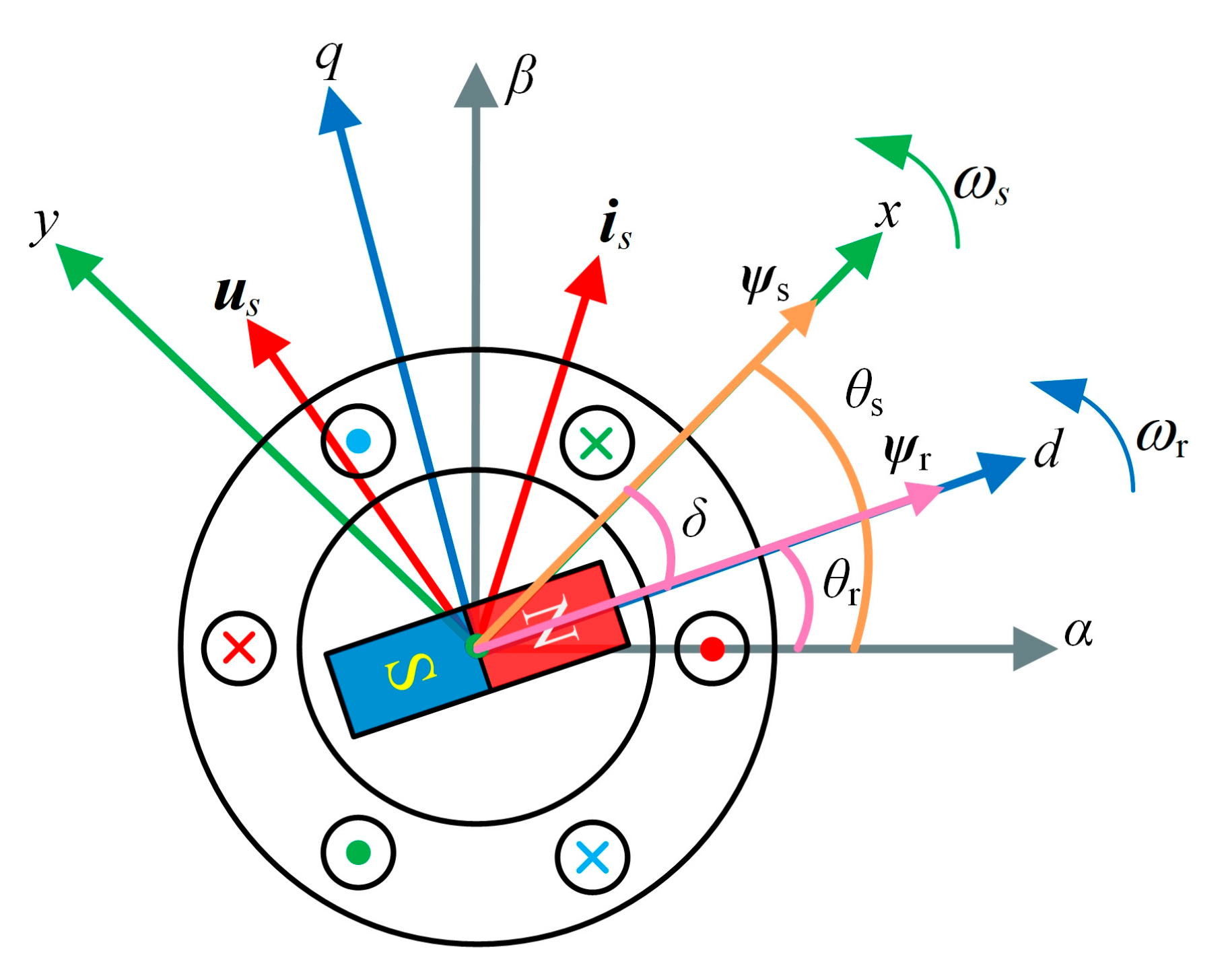
2.1. Definition and Relationship of Each Coordinate System

In the designing process of a PMSM control method, the coupling relationship between the state variables of the PMSM in different coordinate systems is somewhat different. To achieve a simpler mathematical model for the PMSM and simplify the computation of the control process, it is often necessary to analyze the characteristics of the PMSM with the help of different coordinate systems. The distribution of several different coordinate systems used in the paper is shown in Figure 1, where the α β axes are the static coordinate system, d q axes the rotor-flux-oriented coordinate system, and xy axes the stator-flux-oriented coordinate system. ψ s ,   ψ r ,   i s , and u s are stator flux vector, rotor flux vector, stator current vector, and stator voltage vector, respectively. ω r   and ω s   represent the rotating electrical angular velocity of rotor flux and stator flux, respectively. r and s are, respectively, the angle of rotor flux position and stator flux position. Define δ as the load angle and from the distribution of the angles at each position in Figure 1 we can know that δ = θ s θ r   [29].

2.2. The Basic Principle of the Traditional DB-DTFC Algorithm

According to the mathematical model of the PMSM, the stator flux equation and the torque equation in the d q axes can be obtained with the following equations:
ψ d = L d i d + ψ f ψ q = L q i q
T e = 3 2 p ( ψ d i q ψ q i d ) = 3 2 p i q i d ( L d L q ) + ψ f
where ψ d , ψ q , i d , and i q are the d -axis components of the stator flux, q -axis components of the stator flux, d -axis components of the stator current, and q -axis components of the stator current, respectively. L d   and L q   are, respectively, the d -axis and q -axis inductances. T e is the electromagnetic torque, ψ f is the amplitude of the permanent-magnet flux, and p is the number of pole pairs.
The stator reference voltage of the traditional DB-DTFC algorithm is solved based on the rotor-flux-oriented coordinate system. According to the mathematical model of the PMSM, the stator voltage equation in the d q axes can be obtained with the following equation:
u d = R s i d + d d t ψ d ω r ψ q u q = R s i q + d d t ψ q + ω r ψ d
where u d and u q are the d -axis components of the stator voltage, and the q -axis components of the stator voltage, respectively. R s is the stator resistance.
From Equations (1) and (3), the differential equations for the stator flux and stator current in the d q   axes can be derived from the following equations:
d d t ψ d = u d R s L d ψ d + R s L d ψ f + ω r ψ q d d t ψ q = u q R s L q ψ q ω r ψ d
d d t i d = 1 L d ( u d R s L d ψ d + R s L d ψ f + ω r ψ q ) d d t i q = 1 L q ( u q R s L q ψ q ω r ψ d )
The derivation of Equation (2) can be computed as the following equation:
d d t T e = 3 2 p i q d d t ψ d + ψ d d d t i q i d d d t ψ q ψ q d d t i d
Substituting Equations (4) and (5) into Equation (6), the new derivation of the torque equation in d q   axes can be achieved with the following equation:
d d t T e = 3 2 p ( L d L q ) u d ψ q + u q ( L d L q ) ψ d + L q ψ f L d L q + ω r ( L q L d ) ( ψ d 2 ψ q 2 ) L q ψ d ψ f L d L q + R s ψ q L d 2 L q 2 ( L q 2 L d 2 ) ψ d L q 2 ψ f
The discrete expression for the torque equation can be computed as the following equation:
d d t T e = T e ( k + 1 ) T e ( k ) T s
where k + 1 represents the next control period, k represents the current control period, and T s is the control period.
Substituting Equation (7) into Equation (8) and discretizing, the discretized torque equation can be achieved with the following equation:
T e ( k + 1 ) T e ( k ) = 3 2 p ( L d L q ) u d ( k ) ψ q ( k ) T s + u q ( k ) ( L d L q ) ψ d ( k ) + L q ψ f T s L d L q + ω r ( k ) T s ( L d L q ) ( ψ d 2 ( k ) ψ q 2 ( k ) ) L q ψ d ( k ) ψ f L d L q + R s ψ q ( k ) T s L d 2 L q 2 ( L d 2 L q 2 ) ψ d ( k ) L q 2 ψ f
According to Equation (9), the expression for the voltage u q k can be rewritten as the following equation:
u q ( k ) T s = A u d ( k ) T s + B
where:
A = ( L d L q ) ψ q ( k ) ( L d L q ) ψ d ( k ) + L q ψ f
B = A L d L q ( L q L d ) ψ q ( k ) 4 ( T e ( k + 1 ) T e ( k ) 3 p ω r T s L d L q ( L d L q ) ( ψ d 2 ( k ) ψ q 2 ( k ) ) L q ψ d ( k ) ψ f R s ψ q ( k ) T s L d 2 L q 2 ( L q 2 L d 2 ) ψ d ( k ) L q 2 ψ f
Discretizing Equation (4) and disregarding the voltage drop across the stator resistance, the discrete stator flux equation can be obtained with the following equation:
ψ d ( k + 1 ) = ψ d ( k ) + u d ( k ) T s ψ q ( k + 1 ) = ψ q ( k ) + u q ( k ) T s
In the torque and flux control, it is usually necessary to keep the stator flux amplitude constant and change the torque angle to achieve torque control. To meet the requirement of constant flux amplitude, it is necessary to make the stator flux amplitude in the next control period equal to its given reference value:
ψ s 2 ( k + 1 ) = ( ψ s ) 2 = ψ d 2 ( k + 1 ) + ψ q 2 ( k + 1 )
where ψ s represents the absolute value, and ψ s * is the reference value of the stator flux.
Substituting Equation (13) into Equation (14):
( ψ s ) 2 = ( ψ d ( k ) + u d ( k ) T s ) 2 + ( ψ q ( k ) + u q ( k ) T s ) 2
Substituting Equation (10) into Equation (15), a quadratic equation for the stator voltage can be obtained. Since Equation (10) is derived from torque Equation (9), the quadratic equation can be considered as a combination of the torque equation and the flux equation to acquire:
( ψ s ) 2 = ( ψ d ( k ) + u d ( k ) T s ) 2 + ( A u d ( k ) T s + B + ψ q ( k ) ) 2
According to Equation (16), the solution of u d k can be described by the following equation:
u d ( k ) = b ± b 2 4 a c 2 a
where:
a = ( 1 + A 2 ) T s 2 b = 2 ψ d 2 ( k ) T s + 2 A T s ( B + ψ q ( k ) ) c = ψ d 2 ( k ) + ( B + ψ q ( k ) ) 2 ( ψ s ) 2
With the above u d k , u q k can be obtained from Equation (10):
u q ( k ) = A u d ( k ) + B T s
The computation process of u d k , u q k in Equations (17) and (19) can be referenced in Figure 2. The circle indicates flux Equation (15), the line indicates Equation (10), and the hexagon represents the six nonzero voltage vectors in the SVM module [20]. x 1 and x 2 represent the two possible solutions of the quadratic Equation (16). From Figure 2, it can be seen that x 1 exceeds the action range of the SVM-based space voltage vector. According to the above analysis, there is only one solution x 2 that satisfies Equation (16).
Let u d * = u d k , u q * = u q k , u α *   and u β *   can be computed with the following equation:
u α u β = cos θ r sin θ r sin θ r cos θ r u d u q
where u α * and u β * are, respectively, the α -axis and β -axis components of the reference stator voltage.
Finally, u α * and u β * are used as the inputs of the SVM module. Then, the DB-DTFC based on rotor-flux-orientated control can be realized.

2.3. The New DB-DTFC Algorithm

The proposed DB-DTFC algorithm applies the stator flux position angle θ s for coordinate transformation and transforms the stator current in the α β axes to the x y axes to obtain i x and i y , which can be described by the following equation:
i x i y = cos θ s sin θ s sin θ s cos θ s i α i β
where i x   and i y are, respectively, the x -axis and y -axis components of the stator current and i α and i β are the α -axis and β -axis components of the stator current, respectively.
According to the mathematical model of the PMSM, the stator voltage equation in the x y axes is obtained as the following equation:
u x = R s i x + d d t ψ x ω s ψ y u y = R s i y + d d t ψ y + ω s ψ x
where u x and u y are, respectively, the x -axis and y -axis components of the stator voltage and ψ x and ψ y are the x -axis and y -axis components of the stator flux, respectively.
In the x y axes, ψ x ,   ψ y , and ω s satisfy the following equations:
ψ x = ψ s ψ y = 0
ω s = ω r + d δ d t
where ψ s is the stator flux amplitude.
Substituting Equations (23) and (24) into Equation (22), the new stator voltage equation in the x y axes can be achieved as the following equation:
u x = R s i x + d d t ψ s u y = R s i y + ( ω r + d δ d t ) ψ s
Equation (25) is discretized using the forward Euler equation to obtain a new discrete expression as the following equation:
u x ( k ) = R s i x ( k ) + ψ s ( k + 1 ) ψ s ( k ) T s u y ( k ) = R s i y ( k ) + ( ω r + δ ( k + 1 ) δ ( k ) T s ) ψ s ( k )
From the above computation process, it can be seen that the proposed DB-DTFC stator voltage solution process is simpler than the traditional DB-DTFC stator voltage solution process. At the same time, the voltage drop across the stator resistance is also considered in the expression of the stator voltage. Therefore, the stator voltage value solved by the proposed DB-DTFC algorithm is more accurate.
To realize deadbeat control, the stator flux amplitude ψ s k + 1 and the load angle δ k + 1 of the next control cycle in Equation (26) are set as the reference values of the stator flux amplitude and the load angle. Then the x y axes components of the stator voltage reference values are acquired as the following equation:
u x = R s i x ( k ) + ψ s ( k ) ψ s ( k ) T s u y = R s i y ( k ) + ( ω r + δ δ ( k ) T s ) ψ s ( k )
where u x * and u y * are, respectively, the x -axis and y -axis components of the reference stator voltage.
According to the above analysis, the stator flux amplitude and the load angle in the k + 1 t h control cycle are used as the reference values in the k t h control cycle. The acquired reference voltages u x * and u y * in the k t h control cycle are given as the inputs to the SVM module. However, due to the time delay of one control cycle in the control system, the reference voltage is not really delivered to the SVM module until the next control period. If the above modulated voltages are applied to the stator winding of the motor, this will cause a large deviation between the motor control state and the reference value.
To compensate for the time delay, it is often necessary to predict the state quantities at the next moment in the deadbeat control. In this paper, we use the discrete mathematical model to realize the prediction of the next control currents. The discrete current equation, stator flux equation, and torque equation in d q   axes are shown in the following Equations (28)–(30) [30]:
i d ( k + 1 ) = ( 1 R s T s L d ) i d ( k ) + u d ( k ) T s L d + ω r ( k ) L q i q ( k ) T s L d i q ( k + 1 ) = ( 1 R s T s L q ) i q ( k ) + u q ( k ) T s L q ω r ( k ) T s ( L d i d ( k ) + ψ f ) L d
ψ d ( k + 1 ) = L d i d ( k + 1 ) + ψ f ψ q ( k + 1 ) = L q i q ( k + 1 )
T e ( k + 1 ) = 3 2 p ( ψ d ( k + 1 ) i q ( k + 1 ) ψ q ( k + 1 ) i d ( k + 1 ) )
According to Equation (28), the amplitude of the stator flux in the k + 1 t h control cycle is obtained as the following equation:
ψ s ( k + 1 ) = ψ d 2 ( k + 1 ) + ψ q 2 ( k + 1 )
With i d k + 1 and i q k + 1 in Equation (28), i α k + 1 and i β k + 1 can be acquired through the inverse Park transformation. With the help of Equation (21), i x k + 1 and i y k + 1 can be acquired based on i α k + 1 and i β k + 1 . Finally, the stator voltages u x k + 1 and u y k + 1 can be acquire with Equation (26) in the k + 1 t h control cycle. The acquired u x k + 1 and u y k + 1 can be used as the reference values:
u x = u x ( k + 1 ) = R s i x ( k + 1 ) + ψ s ( k + 1 ) ψ s ( k + 1 ) T s u y = u y ( k + 1 ) = R s i y ( k + 1 ) + ( ω r + δ δ ( k + 1 ) T s ) ψ s ( k + 1 )
where ψ s k + 1 * is the reference value of the stator flux amplitude of the next control period.
The derivation of the electromagnetic torque can be computed as the following equation:
d d t T e = 3 p ψ s 2 L d L q ψ f L q cos δ + ψ s ( L d L q ) cos 2 δ d d t δ
Discretizing Equation (33) and using the electromagnetic torque and load angle in the k + 1 t h control cycle as the reference value in the k t h control cycle, the following equation can be acquired:
T e T e ( k ) T s = 3 p ψ s ( k ) 2 L d L q ψ f L q cos δ ( k ) + ψ s ( k ) ( L d L q ) cos 2 δ ( k ) δ δ ( k ) T s
where T e * and δ * are, respectively, the reference value of electromagnetic torque and load angle.
From the above current-prediction process, it can be seen that based on the currents i d k and i q k collected in the k t h control cycle, with the help of the discrete mathematical model of the motor, the currents i d k + 1 and i q k + 1 in the k + 1 t h control cycle can be predicted, and then the electromagnetic torque T e k + 1 and the stator flux ψ s k + 1 in the k + 1 t h control cycle can be obtained. When substituting them into Equation (14), the following equation can be achieved:
T e T e ( k + 1 ) T s = 3 p ψ s ( k + 1 ) 2 L d L q δ δ ( k + 1 ) T s Q
where:
Q = ψ f L q cos δ ( k + 1 ) + ψ s ( k + 1 ) ( L d L q ) cos 2 δ ( k + 1 )
Defining the intermediate variable M, the relationship between the electromagnetic torque and the load angle is simplified as the following equation:
δ δ ( k + 1 ) = 1 M T e T e ( k + 1 )
where:
M = 3 p ψ s ( k + 1 ) 2 L d L q ψ f L q cos δ ( k + 1 ) + ψ s ( k + 1 ) ( L d L q ) cos 2 δ ( k + 1 )
Because the control period of the control system is much smaller than the electrical time constant of the stator and the mechanical time constant of the rotor, the rotating electrical angular velocity of rotor flux ω r is considered to remain constant during the control period. Then θ r k + 1 and δ k + 1 can be acquired as the following equations:
θ r ( k + 1 ) = θ r ( k ) + ω r T s
δ ( k + 1 ) = θ s ( k + 1 ) θ r ( k + 1 )
where  θ r k is the angle of rotor flux position of current control period, and θ r k + 1 and θ s k + 1 are, respectively, the angle of the rotor flux position and the stator flux position of the next control period.
Substituting the electromagnetic torque and the load angle into Equation (32), the reference stator voltages in the x y axes can be acquired with the following equation:
u x = u x ( k + 1 ) = R s i x ( k + 1 ) + ψ s ( k + 1 ) ψ s ( k + 1 ) T s u y = u y ( k + 1 ) = R s i y ( k + 1 ) + ω r + T e T e ( k + 1 ) M T s ψ s ( k + 1 )
With the acquired u x * and u y * in Equation (41), u α * and u β * can be computed with the following equation:
u α u β = cos θ s sin θ s sin θ s cos θ s u x u y
Finally, u α * and u β * are used as the inputs of the SVM module. Then, the DB-DTFC based on the stator-flux-orientated control can be realized.

3. System Design

Compared with the traditional DTC control system, the proposed DB-DTFC control system does not contain hysteresis loop controllers and a switching table, but it needs the SVM module to modulate the voltage vector. The application of SVM in the DB-DTFC can improve voltage-control performance.
The basic structure of the proposed DB-DTFC control system is shown in Figure 3. The basic process of the control system can be divided into the following six steps. In the first step, the three-phase currents are sampled in the control period and they are converted to the d q axes to obtain i d k and i q k . In the second step, the stator currents i d k + 1 and i q k + 1 at the next control period are predicted according to i d k and i q k . In the third step, i d k + 1 and i q k + 1 are passed to the torque and flux estimation module to estimate the torque T e k + 1 and flux ψ s k + 1 in the next control period. In the fourth step, the torque T e k + 1 and flux ψ s k + 1 are passed to the proposed DB-DTFC controller and then the stator reference voltages u x * and u y * in the k + 1 t h control cycle are computed according to the basic principle of the DB-DTFC algorithm. In the fifth step, u x * and u y * are transformed to u α * and u β * , which are used as the inputs of the SVM module for voltage modulation. In the sixth step, the modulated voltage is applied to the stator winding of the PMSM in the k + 1 t h control cycle.
The internal structure of the deadbeat controller in Figure 3 is shown in Figure 4, where the intermediate variable M is computed according to Equation (38).
As shown in Figure 4, u x * and u y * are divided into two separate calculation modules. u x * produced from module 1 and u y * produced from module 2 are computed according to Equation (41).

4. Simulation and Results

4.1. Construction of System Simulation Platform

According to the detailed introduction of the proposed DB-DTFC control for the PMSM, the simulation model can be built with MATLAB/Simulink, which is shown in Figure 5. The proposed DB-DTFC control-system model mainly consists of the Subsystem1 module, Subsystem2 module, SVM module, PWM inverter, and PMSM model.
The Subsystem1 module is the prediction module of the control system and the structure inside this module is shown in Figure 6.
As shown in Figure 6, the detected stator three-phase currents i a , i b , and i c , and the voltages u d , u q , ω m , and θ r in the k t h control cycle are used in current prediction. The MATLAB function module is the realization of Equation (28). The flux and torque in the k + 1 t h control cycle can be obtained according to Equations (29) and (30).
The Subsystem2 module is a deadbeat controller module, and the internal structure of this module is shown in Figure 7.
As shown in Figure 7, ψ s , T e , δ , ω r , i x , and i y predicted by the Subsystem1 module in the k + 1 t h control cycle are the inputs of the deadbeat controller. Then u x * and u y * in the k + 1 t h control cycle can be calculated by the Subsystem 2 module.

4.2. System Simulation and Results

To confirm the correctness and the effectiveness of the PMSM control system with the proposed DB-DTFC algorithm, the parameters of the PMSM are given in Table 1.
The speed of the PMSM controlled by the proposed DB-DTFC algorithm is set to 1300 r/min and the initial load is set to 5 N·m. The corresponding simulation results are shown in Figure 8.
From the simulation results, it can be seen that the PMSM can quickly and accurately track the reference speed. The output electromagnetic torque ripple is small and the flux trajectory is an ideal circle. To test the transient state performance of the PMSM control system based on the proposed DB-DTFC algorithm, the speed of the PMSM is set to 1300 r/min and the initial load is set to 5 N·m. The load torque is set to 6 N·m at 0.2 s and 5 N·m at 0.3 s. During the testing process, the speed is always kept constant at 1300 r/min. The simulation results are shown in Figure 9, where Figure 9a,b show the speed change waveform and the torque change waveform, respectively. According to the simulation results, it can be seen that the proposed DB-DTFC algorithm can realize fast speed and torque response.

5. Discussion

5.1. Comparison on Torque Control

To compare the proposed DB-DTFC algorithm with the DTC algorithm and the SVM-DTFC algorithm, the PMSM load torque is set to 12 N·m and the speeds are set to 500 r/min and 1500 r/min, respectively. The corresponding simulation results are shown in Figure 10.
From Figure 10, it can be seen that the torque ripple of the proposed DB-DTFC algorithm is reduced significantly compared to the DTC algorithm and the SVM-DTFC algorithm. The proposed DB-DTFC algorithm has the lowest torque ripple.

5.2. Comparison of Torque Ripple Reduction

To compare the torque-ripple-reduction effect of the DTC algorithm, the SVM-DTFC algorithm, and the proposed DB-DTFC algorithm, the variable TRP is defined to represent the torque ripple magnitude. Its expression is shown as the following equation:
T R P = T max T l T l × 100 %
where  T m a x is the maximum torque when the motor is running in a steady state and T l is the load torque.
According to the TRP value, the torque ripple reduction of the DTC algorithm, the SVM-DTFC algorithm, and the proposed DB-DTFC algorithm can be compared under different speed or load conditions. The specific comparison results are shown in Figure 11, where Figure 11a shows the variation curve of the torque ripple with a speed under the rated load condition and Figure 11b shows the variation curve of the torque ripple with a load under the rated speed.
From Figure 11, it can be seen that among the three control algorithms, the proposed DB-DTFC algorithm has the most robust control performance and the lowest torque ripple. In particular, the torque ripple of the proposed DB-DTFC algorithm is reduced about 6% in a limited speed range in comparison with the DTC algorithm.

6. Conclusions

In this paper, we propose a new DB-DTFC algorithm. This algorithm uses the forward Euler equation to acquire the reference voltage in a stator coordinate system, which is simpler than the traditional DB-DTFC algorithm for the process of computing the reference voltage. At the same time, the acquired stator reference voltage is more accurate because the voltage drop across the stator resistance is also taken into account in the solution process. Besides, compared with the DTC algorithm, the proposed DB-DTFC algorithm does not contain hysteresis loop controllers and a switching table, while it applies the SVM module to modulate the voltage vector. The application of SVM in the DB-DTFC can improve the voltage control performance. Simulation results show that the PMSM has good static and dynamic performance with the proposed DB-DTFC algorithm, and is better than the DTC algorithm and the SVM-DTFC algorithm for torque and flux control.
In the future, the proposed DB-DTFC algorithm will be tested in a real experimental platform. In addition, there are many current prediction methods available today and in the next work we will also try to use different current prediction methods to achieve a better deadbeat control.

Author Contributions

Conceptualization, J.W.; methodology, J.W., B.Y. and J.C.; software, J.W. and J.C.; validation, J.W. and J.C.; formal analysis, J.C. and B.Y.; investigation, J.C. and B.Y.; resources, J.W.; data curation, J.C.; writing—original draft preparation, J.W. and J.C.; writing—review and editing, J.C. and J.W.; visualization, J.C.; supervision, J.W.; project administration, J.W.; funding acquisition, J.W. All authors have read and agreed to the published version of the manuscript.

Funding

The work is supported by the National Natural Science Foundation of China under Grant 61873079 and the Key Research and Development Plan of Zhejiang Province of China under Grant 2021C03034.

Institutional Review Board Statement

Not applicable.

Informed Consent Statement

Not applicable.

Data Availability Statement

Not applicable.

Acknowledgments

The author thanks the anonymous reviewers for their constructive comments and the editor for handing the paper.

Conflicts of Interest

The authors declare no conflict of interest.

References

  1. Vafaie, M.H.; Mirzaeian Dehkordi, B.; Moallem, P.; Kiyoumarsi, A. A New Predictive Direct Torque Control Method for Improving Both Steady-State and Transient-State Operations of the PMSM. IEEE Trans. Power Electron. 2016, 31, 3738–3753. [Google Scholar] [CrossRef]
  2. Gao, C.; Nie, Y.; Si, J.; Fu, Z.; Feng, H. Mode Recognition and Fault Positioning of Permanent Magnet Demagnetization for PMSM. Energies 2019, 12, 1644. [Google Scholar] [CrossRef] [Green Version]
  3. Zhou, K.; Ai, M.; Sun, D.; Jin, N.; Wu, X. Field Weakening Operation Control Strategies of PMSM Based on Feedback Linearization. Energies 2019, 12, 4526. [Google Scholar] [CrossRef] [Green Version]
  4. Niewiara, Ł.J.; Szczepański, R.; Tarczewski, T.; Grzesiak, L.M. State Feedback Speed Control with Periodic Disturbances Attenuation for PMSM Drive. Energies 2022, 15, 587. [Google Scholar] [CrossRef]
  5. Hao, Z.; Yang, Y.; Gong, Y.; Hao, Z.; Zhang, Z.; Song, H.; Zhang, J. Linear/Nonlinear Active Disturbance Rejection Switching Control for Permanent Magnet Synchronous Motors. IEEE Trans. Power Electron. 2021, 36, 9334–9347. [Google Scholar] [CrossRef]
  6. Wang, W.; Tan, F.; Wu, J.; Ge, H.; Wei, H.; Zhang, Y. Adaptive Integral Backstepping Controller for PMSM with AWPSO Parameters Optimization. Energies 2019, 12, 2596. [Google Scholar] [CrossRef] [Green Version]
  7. Tang, Z.; Akin, B. A New LMS Algorithm Based Deadtime Compensation Method for PMSM FOC Drives. IEEE Trans. Ind. Appl. 2018, 54, 6472–6484. [Google Scholar] [CrossRef]
  8. Candelo-Zuluaga, C.; Riba, J.-R.; Garcia, A. PMSM Parameter Estimation for Sensorless FOC Based on Differential Power Factor. IEEE Trans. Instrum. Meas. 2021, 70, 1–12. [Google Scholar] [CrossRef]
  9. Zhang, X.; Cheng, Y.; Zhao, Z.; Yan, K. Optimized Model Predictive Control with Dead-Time Voltage Vector for PMSM Drives. IEEE Trans. Power Electron. 2021, 36, 3149–3158. [Google Scholar] [CrossRef]
  10. Wang, Z.; Zhang, X.; Guo, Y. Three-Vector Predictive Current Control for Interior Permanent Magnet Synchronous Motor. In Proceedings of the 2021 IEEE International Conference on Predictive Control of Electrical Drives and Power Electronics (PRECEDE), Jinan, China, 20–22 November 2021; pp. 443–448. [Google Scholar]
  11. Gong, Z.; Zhang, C.; Ba, X.; Guo, Y. Improved Deadbeat Predictive Current Control of Permanent Magnet Synchronous Motor Using a Novel Stator Current and Disturbance Observer. IEEE Access. 2021, 9, 142815–142826. [Google Scholar] [CrossRef]
  12. Zhang, X.; Hou, B. Double Vectors Model Predictive Torque Control Without Weighting Factor Based on Voltage Tracking Error. IEEE Trans. Power Electron. 2018, 33, 2368–2380. [Google Scholar] [CrossRef]
  13. Zhong, L.; Rahman, M.F.; Hu, W.Y.; Lim, K.W. Analysis of direct torque control in permanent magnet synchronous motor drives. IEEE Trans. Power Electron. 1997, 12, 528–536. [Google Scholar] [CrossRef]
  14. Bao, G.; Qi, W.; He, T. Direct Torque Control of PMSM with Modified Finite Set Model Predictive Control. Energies 2020, 13, 234. [Google Scholar] [CrossRef] [Green Version]
  15. Wang, D.; Yuan, T.; Wang, X.; Wang, X.; Li, W. A Composite Vectors Modulation Strategy for PMSM DTC Systems. Energies 2018, 11, 2729. [Google Scholar] [CrossRef] [Green Version]
  16. Abassi, M.; Khlaief, A.; Saadaoui, O.; Chaari, A.; Boussak, M. Performance analysis of FOC and DTC for PMSM drives using SVPWM technique. In Proceedings of the International Conference on Sciences and Techniques of Automatic Control and Computer Engineering (STA), Monastir, Tunisia, 21–23 December 2015; pp. 223–228. [Google Scholar]
  17. Ren, Y.; Zhu, Z.Q.; Green, J.E.; Li, Y.; Zhu, S.; Li, Z. Improved Duty-Ratio-Based Direct Torque Control for Dual Three-Phase Permanent Magnet Synchronous Machine Drives. IEEE Trans. Ind. Appl. 2019, 55, 5843–5853. [Google Scholar] [CrossRef]
  18. Tang, L.; Zhong, L.; Rahman, M.F.; Hu, Y. A novel direct torque controlled interior permanent magnet synchronous machine drive with low ripple in flux and torque and fixed switching frequency. IEEE Trans. Power Electron. 2004, 19, 346–354. [Google Scholar] [CrossRef]
  19. Basar, M.S.; Bech, M.M.; Andersen, T.O.; Scavenius, P.; Thomas-Basar, T. Comparison of sensorless FOC and SVM-DTFC of PMSM for low-speed applications. In Proceedings of the 4th International Conference on Power Engineering, Energy and Electrical Drives, Istanbul, Turkey, 13–17 May 2013; pp. 864–869. [Google Scholar]
  20. Lee, J.S.; Choi, C.H.; Seok, J.K.; Lorenz, R.D. Deadbeat-direct torque and flux control of interior permanent magnet synchronous machines with discrete time stator current and stator flux linkage observer. IEEE Trans. Ind. Appl. 2011, 47, 1749–1758. [Google Scholar] [CrossRef]
  21. Dastjerdi, R.S.; Abbasian, M.A.; Saghafi, H.; Vafaie, M.H. Performance Improvement of Permanent-Magnet Synchronous Motor Using a New Deadbeat-Direct Current Controller. IEEE Tran. Power Electron. 2019, 34, 3530–3543. [Google Scholar] [CrossRef]
  22. Lee, J.S.; Lorenz, R.D.; Valenzuela, M.A. Time-optimal and loss-minimizing deadbeat-direct torque and flux control for interior permanent-magnet synchronous machines. IEEE Trans. Ind. Appl. 2014, 50, 1880–1890. [Google Scholar] [CrossRef]
  23. Xie, W.; Wang, X.; Wang, F.; Xu, W.; Kennel, R.M.; Gerling, D.; Lorenz, R.D. Finite-control-set model predictive torque control with a deadbeat solution for PMSM drives. IEEE Trans. Ind. Electron. 2015, 62, 5402–5410. [Google Scholar] [CrossRef]
  24. Lee, J.S. Stability Analysis of Deadbeat-Direct Torque and Flux Control for Permanent Magnet Synchronous Motor Drives with Respect to Parameter Variations. Energies 2018, 11, 2027. [Google Scholar] [CrossRef] [Green Version]
  25. Scarcella, G.; Scelba, G.; Pulvirenti, M.; Lorenz, R.D. Fault-Tolerant Capability of Deadbeat-Direct Torque and Flux Control for Three-Phase PMSM Drives. IEEE Trans. Ind. Appl. 2017, 53, 5496–5508. [Google Scholar] [CrossRef]
  26. Vafaie, M.H.; Dehkordi, B.M.; Moallem, P.; Kiyoumarsi, A. Improving the Steady-State and Transient-State Performances of PMSM Through an Advanced Deadbeat Direct Torque and Flux Control System. IEEE Trans. Power Electron. 2017, 32, 2964–2975. [Google Scholar] [CrossRef]
  27. Saur, M.; Gaona Erazo, D.E.; Zdravkovic, J.; Lehner, B.; Gerling, D.; Lorenz, R.D. Minimizing Torque Ripple of Highly Saturated Salient Pole Synchronous Machines by Applying DB-DTFC. IEEE Trans. Ind. Appl. 2017, 53, 3643–3651. [Google Scholar] [CrossRef]
  28. Flieh, H.M.; Lorenz, R.D.; Totoki, E.; Yamaguchi, S.; Nakamura, Y. Dynamic Loss Minimizing Control of a Permanent Magnet Servomotor Operating Even at the Voltage Limit When Using Deadbeat-Direct Torque and Flux Control. IEEE Trans. Ind. Appl. 2019, 55, 2710–2720. [Google Scholar] [CrossRef]
  29. Koç, M.; Wang, J.; Sun, T. An inverter nonlinearity-independent flux observer for direct torque-controlled high-performance interior permanent magnet brushless AC drives. IEEE Trans. Power Electron. 2016, 32, 490–502. [Google Scholar] [CrossRef] [Green Version]
  30. Preindl, M.; Bolognani, S. Model Predictive Direct Speed Control with Finite Control Set of PMSM Drive Systems. IEEE Trans. Power Electron. 2013, 28, 1007–1015. [Google Scholar] [CrossRef]
Figure 1. Distribution of the position of each coordinate axis.
Energies 15 03009 g001
Figure 2. Schematic diagram of the stator voltage solution for traditional deadbeat torque and flux control.
Energies 15 03009 g002
Figure 3. The DB-DTFC control system structure.
Energies 15 03009 g003
Figure 4. Internal structure of a deadbeat controller.
Energies 15 03009 g004
Figure 5. Simulation model of the DB-DTFC control system for the PMSM.
Energies 15 03009 g005
Figure 6. Subsystem1 model.
Energies 15 03009 g006
Figure 7. Subsystem2 model.
Energies 15 03009 g007
Figure 8. (a) Speed tracking waveform; (b) torque waveform; (c) phase current waveform; (d) phase voltage waveform; and (e) stator-flux-motion trajectory.
Energies 15 03009 g008
Figure 9. (a) Partial enlargement of speed tracking waveform; and (b) partial enlargement of electromagnetic torque waveform.
Energies 15 03009 g009
Figure 10. Torque at 500 r/min and 1500 r/min: (a) DTC algorithm; (b) SVM-DTFC algorithm; and (c) DB-DTFC algorithm.
Energies 15 03009 g010
Figure 11. (a) Torque ripple versus speed; and (b) torque ripple versus load.
Energies 15 03009 g011
Table 1. Motor model parameter table.
ParametersValue
Number of stator pole pairs3
Permanent-magnet flux0.483 Wb
Stator resistance3.3 Ω
d/q -axis stator inductance41.6/57.1 mH
Rated power2200 W
Rated speed1750 r/min
Rated torque12 N·m
Rated current/voltage4.1 A/380 V
DC-link voltage540 V
The moment of inertia 0.005   kg m2
Publisher’s Note: MDPI stays neutral with regard to jurisdictional claims in published maps and institutional affiliations.

