Abstract
The interpretation of subsurface fluid flow features in seismic reflection data is a key part of identifying the presence of hydrocarbon and active petroleum systems. Currently, this kind of study is mainly conducted utilizing offshore seismic reflection data with very limited cases utilizing onshore seismic reflection data. In addition, the Alamein basin is an area of prolific study in onshore Egypt, with most related studies concentrating on basin analysis and reservoir characterization. Therefore, in our study we aimed to make practical and effective use of onshore seismic reflection data with seismic attribute analysis to describe seismic facies, delineating and interpreting subsurface fluid flow features. The relatively vertical V-shaped and pipe or concave-up-shaped features with distorted reflections inside them are revealed through the analysis of variance, sweetness, chaos, instantaneous frequency and the RMS amplitude of seismic attributes. These subsurface fluid flow features are a product of mature source rock that migrates hydrocarbon vertically through faults (especially deep-seated faults) and fracture systems (fault and fracture-related subsurface fluid flow features). The classification scheme presented in our study could be implemented in the onshore case worldwide.
1. Introduction
Subsurface fluid flow is a localized vertical or sub-vertical and narrow feature that is usually imaged on seismic reflection data with a columnar zone, a disrupted and chaotic reflection configuration, a dimmed amplitude (sometimes low amplitude), or degraded seismic data and velocity anomalies [1,2,3,4]. This feature is important piece of information in an active petroleum system, providing an indication of where hydrocarbon-filled traps leak (the hydrocarbon plumbing system) vertically to the surface or to other shallower traps [5,6], and as an important migration feature in the geothermal, magmatic, groundwater, CO2 storage and other subsurface systems [1]. Overpressure in the sedimentary basin is usually caused by the amount of pore pressure in the formation that exceeds the hydrostatic pressure for a given depth as a result of fluid expansion and compressible rock stress [7,8,9]. High pressure in the formation could create fractures (after exceeding the sealing capacity) that act as fluid conduits, flowing towards areas of lower pressure (usually at a shallower depth).
Seismic attributes play an important role in identifying and delineating subsurface fluid flow from seismic reflection data in the energy industry and in subsurface characterization. Basic seismic reflection components, both in pre-stack or post-stack data (i.e., time, amplitude, frequency and attenuation), are used during seismic attribute computation, using either the horizon or window-based interval [10,11,12]. In terms of subsurface fluid flow, some seismic attributes are well-known to be useful to identify and delineate these features, for example, apparent polarity, envelope (reflection strength), instantaneous frequency, chaos, root-mean-square (RMS) amplitude, sweetness, and variance. Nevertheless, we should only use those seismic attributes that are related to a specific feature and to physical properties of interest, and the interpreter should always provide ground truths in relation to the results of seismic attribute analysis.
The study area at the Alamein Basin (Figure 1) is one of the greatest basins in the Western desert of Egypt, containing mature and economic oil and gas accumulations. Recent and past research in the study area has focused largely on petrophysical heterogeneity and reservoir characterization [13,14,15,16,17], basin modeling and the seismic interpretation of structural geology [18,19,20]. In addition, most of the subsurface-focused fluid flow studies worldwide have utilized marine seismic data, e.g., [1,2,5,21,22,23,24,25,26]. These provide an impetus to characterize subsurface fluid flow features that are relatively poorly interpreted in the onshore study area. Therefore, in our study, we have utilized 2D seismic reflection data with seismic attribute techniques to (1) describe seismic facies, as well as to (2) delineate and (3) interpret subsurface fluid flow features. Our findings enable us to discuss the mechanism that controls subsurface fluid flow and to perform a comparison with other similar systems that support subsurface fluid flow features as hydrocarbon indicators. The seismic facies classification, seismic attributes and the conceptual model of subsurface fluid flow feature that we present in this study could be used to predict the presence of subsurface fluid flow, indicating the existence of an active petroleum system in particular onshore areas worldwide.
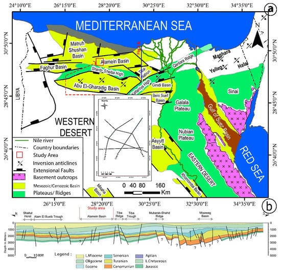
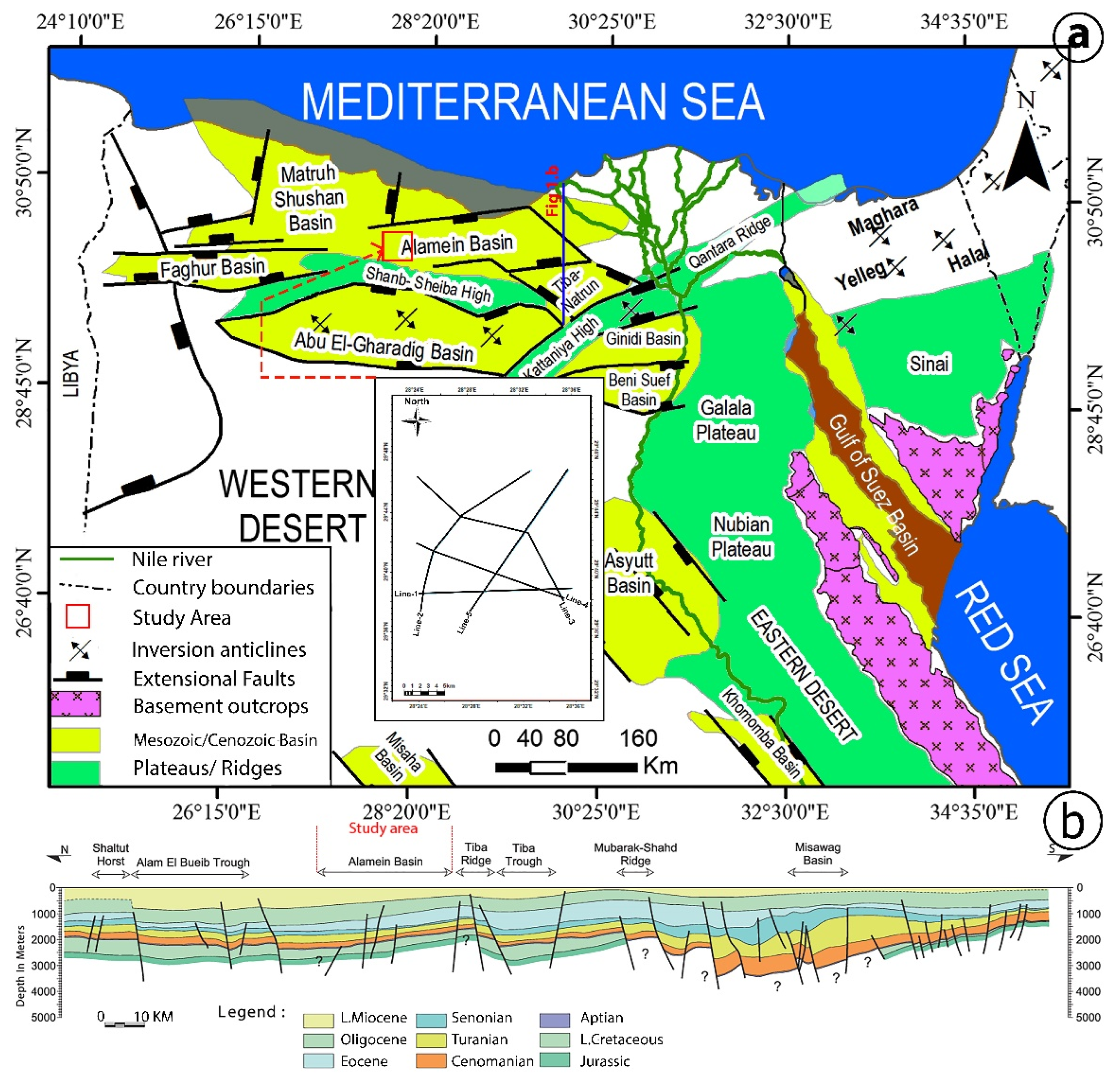
Figure 1.
(a) Regional structural elements of the study area (modified from the work of Elmahdy, Tarabees, Bakr and Farag [20]) with (b) regional geological cross-section (modified from the work of Moretti, Kerdraon, Rodrigo, Huerta, Griso, Sami, Said and Ali [19]).
2. Regional Geology
The Alamein Basin is located in the northwestern part of Egypt, situated both in onshore and offshore areas (Figure 1a). This basin is bounded by the Dabaa platform on the Mediterranean Sea in the north, the Shanb-Sheiba high in the south, and several bounding faults in the west and east that separate the Alamein Basin from other surrounding basins (Figure 1a). The tectono-stratigraphic evolution at the Alamein Basin can be divided into (1) Triassic to mid-Jurassic rifting, (2) Lower Cretaceous passive subsidence, (3) Upper Cretaceous onset of inversion Syrian Arc structures, and (4) Miocene to recent [27,28,29,30]. The main rift phase in the Alamein Basin is considered to be the Mid-Jurassic age [31], when the onset of collision occurred in the Tethys Ocean and resulted in a general uplift with the inversion of the half-grabens formed during Jurassic rifting [30,32]. During the Lower Cretaceous, which is considered to be a tectonically quiet phase of thermal sag in the area, there was normal faulting that might have continued and created uplift and erosion due to footwalls. In the Upper Cretaceous, the compressive event was more precisely dated to 83–85 Ma by Letouzey [32], who noted the huge spatial spread of this phase, which spanned most of North Africa and southwards into Syria and which they linked to a shift in the South Atlantic spreading vector.
The northwestern desert of Egypt was a vast shelf area along the southern boundary of the Neo-Tethys and remained around the submarine environment throughout the Mesozoic and much of the Cenozoic, with local uplift and erosion resulting from all tectonic stages. During the Upper Cretaceous, the structural configuration development appears to have reached its maximum and has shown additional rejuvenation during the Cenozoic [28,29,30]. The sedimentary thickness of this northwestern desert of Egypt is approximately 4000 m (Figure 1b), which consists of alternating cycles of clastic and carbonates of Jurassic to Miocene deposits due to many successive transgressions and regressions on this shelf environment.
Furthermore, the Alamein Basin is an elongated NE–SW plunging anticline that constitutes the regional Shanb-Sheiba high, dissected by a major fault system, trending in the NE–SW directions (Figure 1a). This Shanb-Sheiba high also shows the same direction as that of the Syrian Arc folding system, in which the Alamein area is the most prominent structural configuration, consisting of extensional faults which extended up into the Lower Cretaceous section (Figure 1b). Faults within the Alamein Basin formed a series of graben that cuts the crestal part of the structure into two blocks, where the faulting ceased until very late Maastrichtian to Turonian times [28,29]. Inversion itself was formed through fault reactivation over the downthrown side of the old extensional faults. This kind of fault system later acted as a conduit that migrated fluid from the source rock in the lower part to the reservoir rock above and the surface, indicating an active petroleum system in the study area.
3. Data and Methods
The primary dataset for this study consisted of onshore full-stack 2D seismic reflection data that were acquired by GUPCO in 1987 with a 96-fold common depth point, using vibroseis as a source of energy. The data are zero-phased and displayed in Society of Exploration Geophysicist (SEG) reverse polarity, where an increase in acoustic impedance is represented by a through or negative amplitude value, whereas the decrease in acoustic impedance is represented by a peak or positive amplitude value (e.g., Figure 2a). These 2D seismic reflection data have a dominant frequency of 30 Hz, with an average velocity of 6800 m/s in the interval of interest (200–1000 ms), providing a vertical resolution of 56 m. The quality of 2D seismic reflection data in the study area is relatively good, with minimum seismic noise and artifacts. Furthermore, this dataset has never been used before for seismic interpretation of fluid flow features in the study area and is a rare onshore dataset that contains fluid flow features.
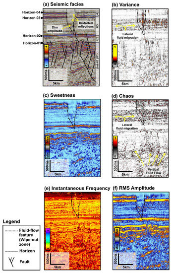
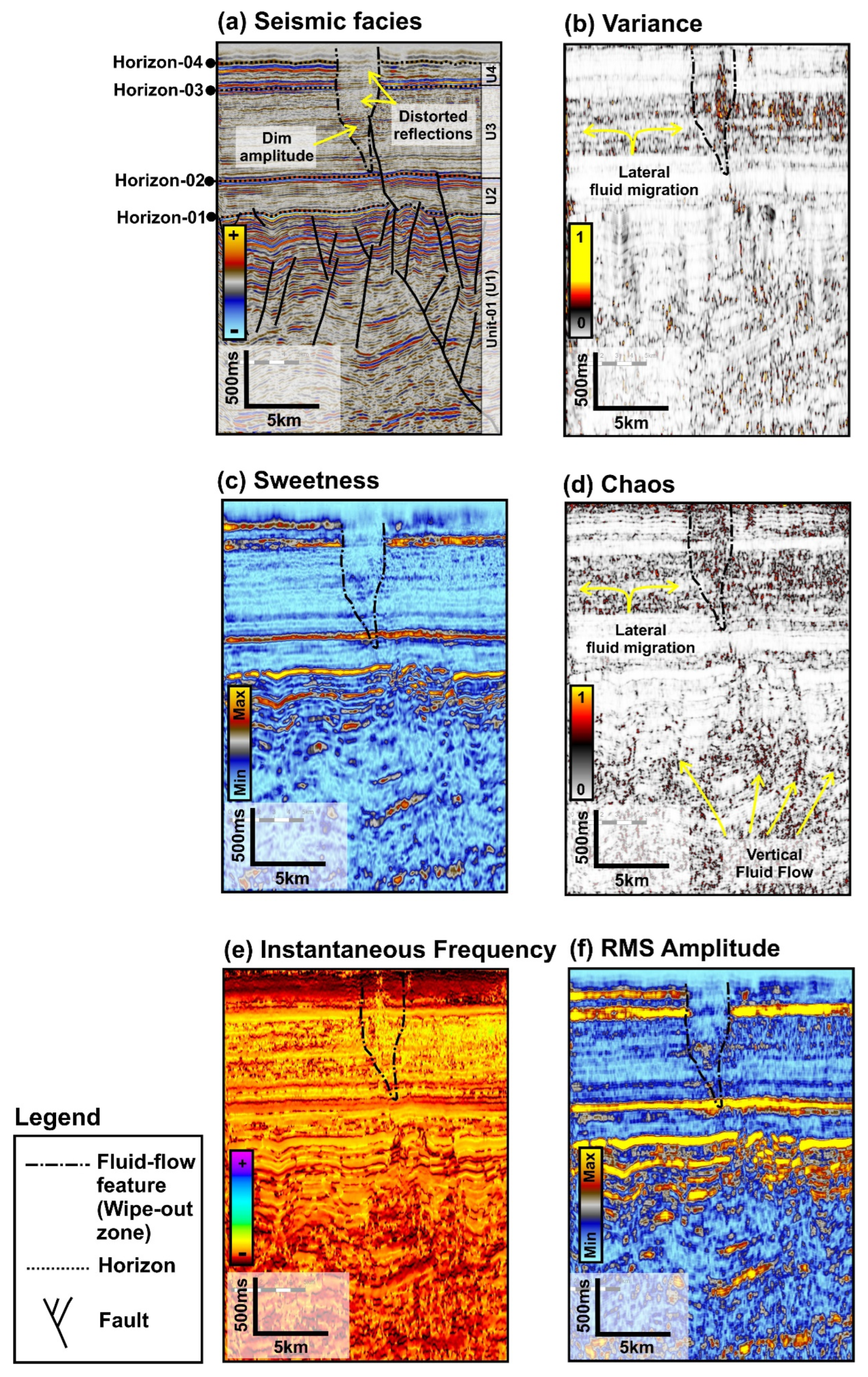
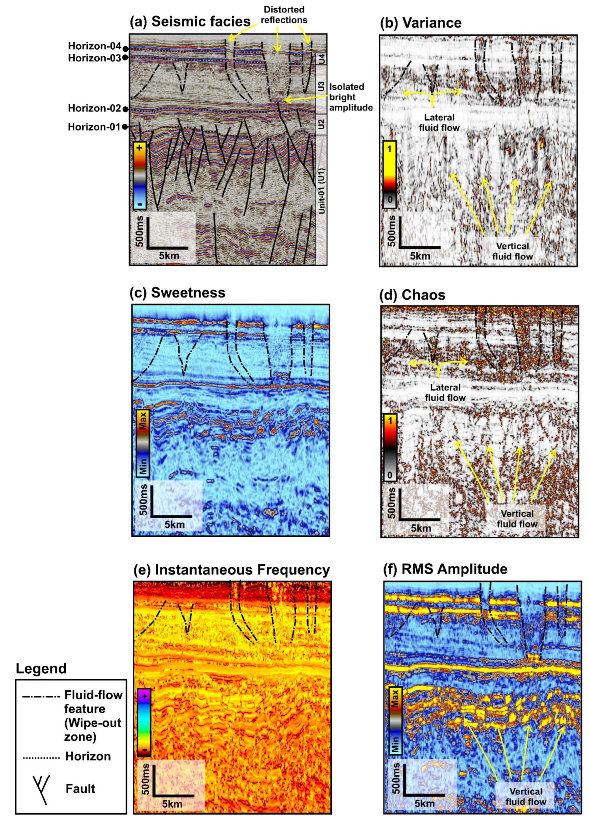
Figure 2.
(a) Seismic facies and seismic attributes of line 1; (b) variance, (c) sweetness, (d) chaos, (e) instantaneous frequency, and (f) RMS amplitude, with fluid flow feature interpretation. See Figure 1a for section location.
The seismic interpretation was mainly carried out using industrial Schlumberger Petrel software, in which several main horizons and faults were interpreted in the study area. Furthermore, seismic facies analysis was undertaken to describe the seismic sedimentary unit and seismic response to fluid in the study area and the implemented seismic facies classification based on the work of Mitchum Jr, et al. [33]. Seismic attribute analysis was performed on the available 2D seismic reflection dataset in the study area in order to be able to identify and delineate subsurface fluid flow features. These features include variances that measure how well each seismic trace fits with the mean trace to produce a volume of discontinuity [10,11]; sweetness, which is a function of the average frequency and trace envelope [10,34]; chaos, defined as the irregularity of each seismic trace [10,11]; instantaneous frequency, defined as the derivative of phase with a time that represents the mean amplitude of the wavelet [10,11,35]; and root-mean-square (RMS) amplitude, which is a function of the square root of the sum amplitude within the window interval [10,11,34,35].
4. Results
4.1. Interpretation of Fault, Horizon, and Seismic Facies
Faults were interpreted in all available seismic amplitude sections and consisted of normal, reverse, and inversion faults. Most of the seismic sections contained a deep-seated fault that crossed the lower sedimentary layer up to Horizon-02, whereas other types of faults (i.e., normal and reverse faults) displaced sedimentary layers in particular intervals among the horizons (Figure 2a, Figure 3a, Figure 4a, Figure 5a and Figure 6a). In addition, some fractures might have existed especially in the near-surface and deeper areas, but the dimensions of the fracture (cm to m scale) are below the resolution of the seismic data in the study area. Major displacement between two or more different horizons occurred in some faults in the study area (e.g., Horizon 01 as shown in Figure 3a and Figure 6a, and reflectors at Unit-01), whereas other faults have a minimum displacement (e.g., Horizons 02 to 04, shown in Figure 3a, Figure 4a, Figure 5a and Figure 6a).
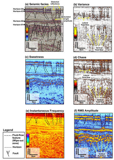
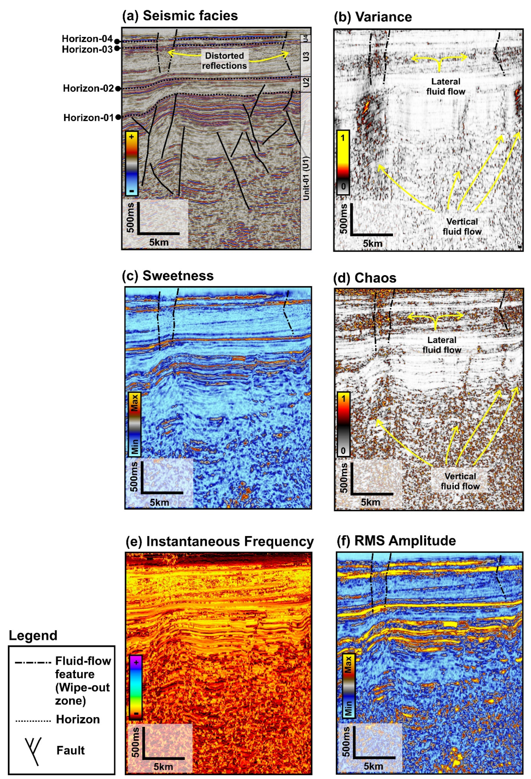
Figure 3.
(a) Seismic facies and seismic attributes of line 2; (b) variance, (c) sweetness, (d) chaos, (e) instantaneous frequency, and (f) RMS amplitude, with fluid flow feature interpretation. See Figure 1a for section location.
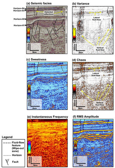
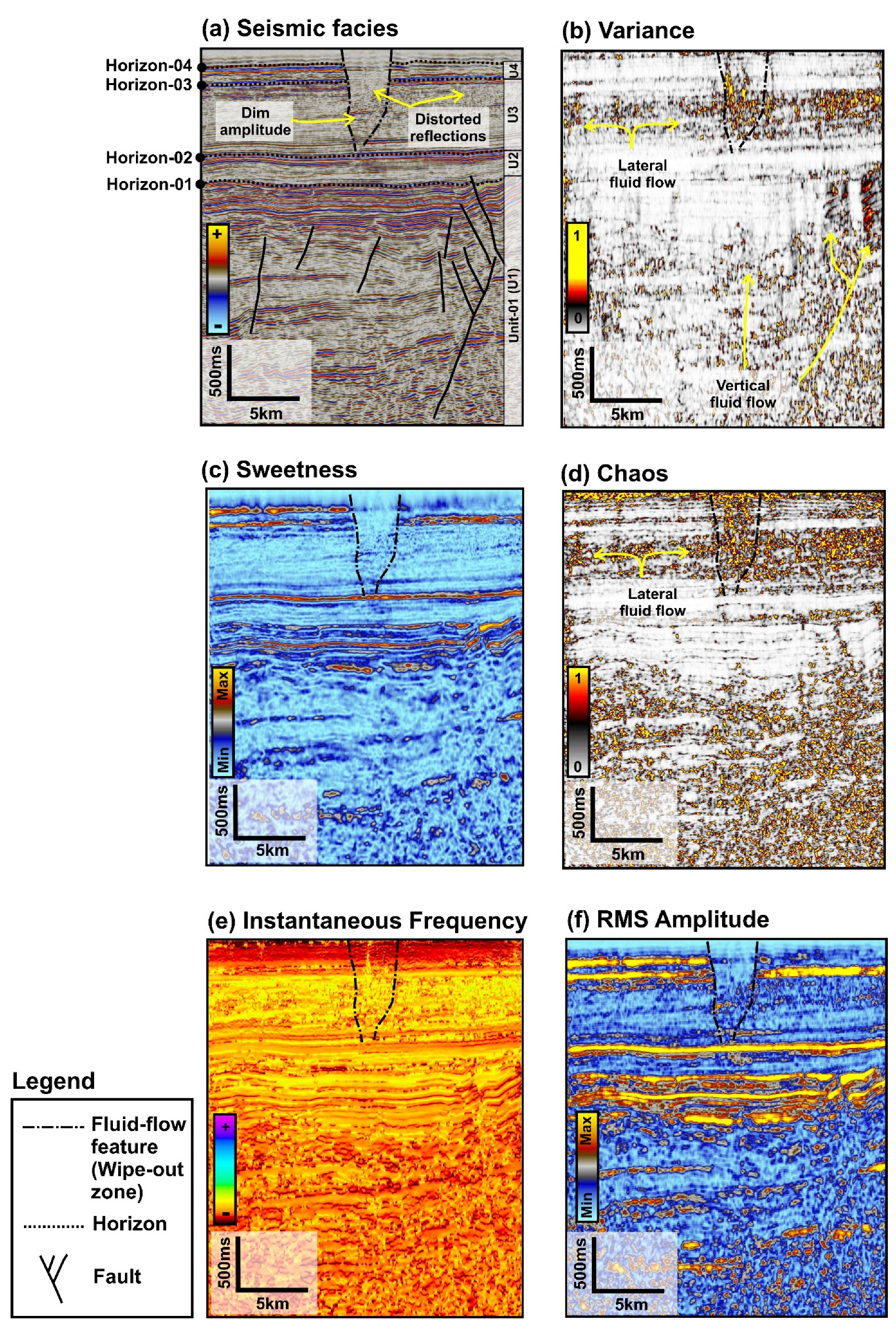
Figure 4.
(a) Seismic facies and seismic attributes of line 3; (b) variance, (c) sweetness, (d) chaos, (e) instantaneous frequency, and (f) RMS amplitude, with fluid flow feature interpretation. See Figure 1a for section location.
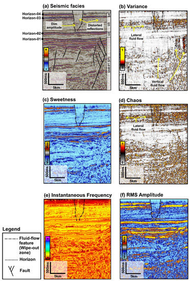
Figure 5.
(a) Seismic facies and seismic attributes of line 4; (b) variance, (c) sweetness, (d) chaos, (e) instantaneous frequency, and (f) RMS amplitude, with fluid flow feature interpretation. See Figure 1a for section location.

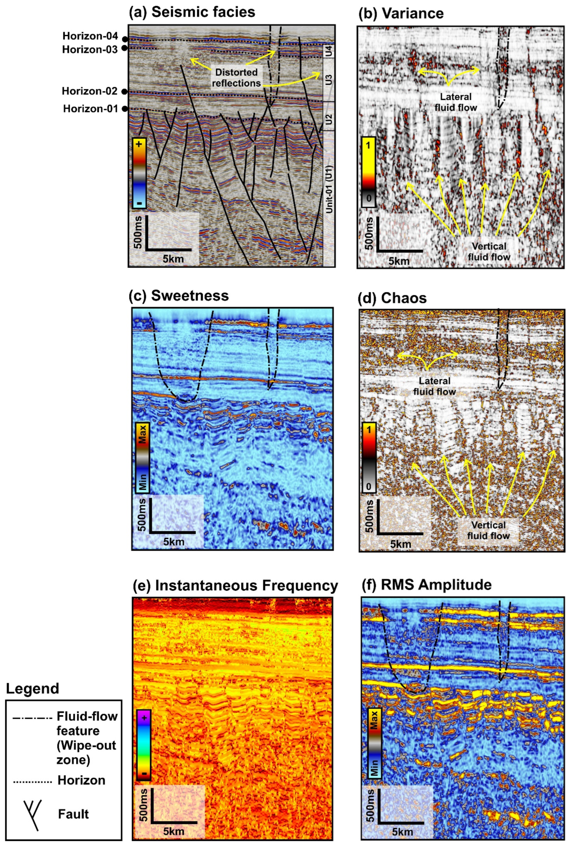
Figure 6.
(a) Seismic facies and seismic attributes of line 5; (b) variance, (c) sweetness, (d) chaos, (e) instantaneous frequency, and (f) RMS amplitude, with fluid flow feature interpretation. See Figure 1a for section location.
Four main horizons were interpreted on the seismic data that directly divided the seismic section into four main seismic units. Horizon-01 is the lowest horizon (top of unit-01), which consists of a medium to high amplitude with a relatively continuous reflector. In some parts, this unit is disturbed by faults and tectonic inversion, creating an anticlinorium system with a series of normal and reverse faults (Figure 2a, Figure 3a, Figure 4a, Figure 5a and Figure 6a). Furthermore, unit-01 is also characterized by relatively a low to high amplitude (lower and upper part of its section, respectively) with parallel to sub-parallel and distorted reflection of seismic amplitude (Figure 2a, Figure 3a, Figure 4a, Figure 5a and Figure 6a). In addition, there is no seismic reflection termination on unit-01.
Horizon-02 (Top of unit-02) is characterized by a high seismic amplitude and relatively continuous seismic reflectors (Figure 2a, Figure 3a, Figure 4a, Figure 5a and Figure 6a). This horizon has been disturbed mainly by a series of normal faults on lines 1, 2, and 5 (Figure 2a, Figure 3a and Figure 6a) with a saddle structure, as can be seen on line 3 (Figure 4a). Unit-02 itself is characterized by relatively low to high amplitude with sub-parallel to hummocky and sub-parallel to parallel reflection configurations at the lower and upper parts of its section, respectively (Figure 2a, Figure 3a, Figure 4a, Figure 5a and Figure 6a). In addition, there is no seismic reflection termination on unit-02.
Distorted reflection is the main feature on Horizon-3 (Top of unit-03), with a relatively continuous and high amplitude (Figure 2a, Figure 3a, Figure 4a, Figure 5a and Figure 6a). This horizon is disturbed in a minor way by a normal fault, which can be seen only on line 5 (Figure 6a). Unit-03 itself is characterized by relatively continuous, medium to high amplitude, parallel to sub-parallel in the lower part, with a hummocky low amplitude and an isolated bright amplitude in the middle part (Figure 2a, Figure 3a, Figure 4a, Figure 5a and Figure 6a). In addition, the upper part of unit-03 is characterized by a relatively sub-parallel with low to high amplitude. Furthermore, relatively vertical V-shaped and pipe or conical-shaped and distorted reflections are apparent from the lower to the upper parts of this unit (Figure 2a, Figure 3a, Figure 4a, Figure 5a and Figure 6a).
Horizon-04 (top of unit-04) is characterized by a continuous and high seismic amplitude with some undulating (Figure 2a, Figure 3a, Figure 4a, Figure 5a and Figure 6a). This horizon exhibits a minor disturbance by a normal fault, which is only located on line 5 (Figure 6a). Unit-04 itself is characterized by relatively low to medium seismic amplitude with a hummocky to sub-parallel reflection configuration (Figure 2a, Figure 3a, Figure 4a, Figure 5a and Figure 6a). This horizon and unit have relatively vertical V- and pipe or conical shaped and distorted reflections inside them and these are apparent from the lower to the upper parts of this unit (Figure 2a, Figure 3a, Figure 4a, Figure 5a and Figure 6a).
4.2. Seismic Attributes of Fluid Flow Features
The relatively vertical V-shaped and pipe or concave-up-shaped features with distorted reflections inside them were revealed through analysis of the variance, sweetness, chaos, instantaneous frequency and RMS amplitude of the seismic attributes (Figure 2, Figure 3, Figure 4, Figure 5 and Figure 6). These features (pipe and concave-up shaped) were interpreted as fluid flow features in the subsurface of the study area.
The distorted reflections have medium to high variance values (sometimes isolated) with relatively vertical trends (Figure 2b, Figure 3b, Figure 4b, Figure 5b and Figure 6b). These features appeared on variance seismic attributes in most of the section area, starting from the lower part and tending to accumulate in a vertical direction (vertical fluid flow) towards the upper part of the study interval. With regard to the upper part, these features also tended to be distributed laterally (especially in unit-03) with the low to high variance values trending in a vertical and lateral direction (Figure 2b, Figure 3b, Figure 4b, Figure 5b and Figure 6b; lateral fluid migration). On the contrary, most of unit-02 on the available seismic line in this study did not show the existence of these features in terms of the variance seismic attribute (Figure 2b, Figure 3b, Figure 4b and Figure 5b).
Relatively minimum sweetness seismic attribute values characterized these features, with vertical V-shaped and pipe or concave-up shaped appearances (Figure 2c, Figure 3c, Figure 4c, Figure 5c and Figure 6c). This value displays the opposite trend to that of the horizon value, which had the maximum sweetness value, indicating a lithological response; thus these features can most probably be interpreted as fluid flow. Furthermore, a distorted sweetness response also appeared on the previous fluid flow feature delineation area of the seismic facies (Figure 2a, Figure 3a, Figure 4a, Figure 5a and Figure 6a) and the seismic attribute of variance (Figure 2b, Figure 3b, Figure 4b, Figure 5b and Figure 6b). Moreover, these sweetness seismic attributes provide a clearer image of the subsurface fluid flow features as a contrast between lithology and fluid components.
These fluid flow features are characterized by relatively high value and distortion of the seismic attribute of chaos (Figure 2d, Figure 3d, Figure 4d, Figure 5d and Figure 6d). These values also corresponded to the lithological response of the chaos seismic attribute, with the difference in geometry and distribution trends with subsurface fluid flow features in the study area. The fluid flow had relatively vertical V-shaped and pipe or concave-up shaped features in relation to this chaos seismic attribute, starting from the lower part with a vertical fluid flow to the upper part of the section, based on the available 2D seismic data in the study area (Figure 2d, Figure 3d, Figure 4d, Figure 5d and Figure 6d). In agreement with the seismic attribute of chaos (Figure 2b, Figure 3b, Figure 4b, Figure 5b and Figure 6b), the seismic attribute of chaos also indicated lateral fluid migration on the upper part of the study interval (unit-03) with a relatively high value of the chaos seismic attribute (Figure 2d, Figure 3d, Figure 4d, Figure 5d and Figure 6d). In addition, most of unit-02 did not show (or showed very limited) subsurface fluid flow features of this type in terms of the chaos seismic attribute.
The attribute of instantaneous frequency only indicated very limited subsurface fluid flow features in the study area. The lower part of the study interval did not indicate any relatively vertical-pipe or isolated instantaneous frequency trends, whereas the upper interval did (Figure 2e, Figure 3e, Figure 4e, Figure 5e and Figure 6e). This trend was also in agreement with that of seismic facies (Figure 2a, Figure 3a, Figure 4a, Figure 5a and Figure 6a) and other previous seismic attributes, i.e., variance (Figure 2b, Figure 3b, Figure 4b, Figure 5b and Figure 6b), sweetness (Figure 2c, Figure 3c, Figure 4c, Figure 5c and Figure 6c), and chaos (Figure 2d, Figure 3d, Figure 4d, Figure 5d and Figure 6d). A relatively minimal value of instantaneous frequency with vertical V- and pipe or concave-up shaped features characterized these subsurface fluid flow features, with a distorted instantaneous frequency and amplitude (Figure 2e, Figure 3e, Figure 4e, Figure 5e and Figure 6e).
The distorted reflection has a relative minimal value in regard to the RMS amplitude of the seismic attribute with a vertical trend. Some isolated and relatively high-RMS amplitude data were located inside these features with vertical and lateral trends (Figure 2f, Figure 3f, Figure 4f, Figure 5f and Figure 6f). These features were interpreted mostly on the upper part of the RMS amplitude section of the available 2D seismic data, whereas line 2 of the RMS amplitude analysis could indicate a clearer image of vertical fluid flow on the lower part of the RMS amplitude section (Figure 3f). In agreement with seismic facies and another seismic attribute, this RMS amplitude analysis also showed the relatively vertical V-shaped and pipe or concave-up-shaped features with distorted reflections inside them (Figure 2f, Figure 3f, Figure 4f, Figure 5f and Figure 6f).
5. Discussion
5.1. Evolution of Subsurface Fluid Flow
Four sedimentary units in the study area were mostly disturbed by fault and fractures (including synthetic and antithetic faults; Figure 7a), with some units being more permeable than others, indicated by the relatively low values of the variance and sweetness seismic attributes (Figure 2, Figure 3, Figure 4, Figure 5 and Figure 6). Furthermore, faults in the study area could be categorized as sealing and non-sealing faults (by juxtaposed means), where a deep-seated normal fault was probably leaking due to the low displacement of the juxtaposed means (sand on sand). These provide a space or conduit for fluid to migrate from the source rock in the deeper part (unit-01) to the reservoir in the shallow part (units-02 to 04) and (through) the deep-seated fault towards the surface (Figure 7a).
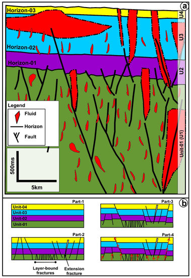
Figure 7.
(a) Conceptual model, and (b) evolution of the fluid flow system in the study area (unscaled). Please note that the red arrow indicates fluid flow migration (see the text for the description).
In the beginning (Part 1), four sedimentary units were deposited during the Late Mesozoic until the Early Cenozoic with dominant sandstone, shale and carbonate (interbedded) on the transgressions and regressions of the marine shelf environment [31,32,36]. Thus, these sedimentary layers are mostly deposited in a relatively flat area, with a continuous seismic reflector with minimum lateral variation and properties (Figure 2a, Figure 3a, Figure 4a, Figure 5a, Figure 6a and Figure 7b).
The second part described the occurrence of fractures in the study area (Figure 7b), due to the overburden from a stack of four sedimentary units that triggered confining pore pressure (burial depth), increasing the differential stress and successfully expelling the critical point [37,38,39,40]. These fractures could be characterized as layer-bound fractures and extension fractures that are mostly located on unit-01 and across all units, respectively (Figure 2a, Figure 3a, Figure 4a, Figure 5a and Figure 6a). At this stage, organic content on the sedimentary unit-01 started the maturation processes due to compensation on the burial depth (an increase in pressure and temperature). Furthermore, part 3 consists of the existence of a fault system on four sedimentary units in the study area (Figure 7b).
This fault system occurred in several tectonic events of extension, compression, and inversion during the Late Mesozoic until the Early Cenozoic, resulting in normal, reverse, and inverted faults that also included anticline and syncline folds [27,28,30]. Lastly, the source rock matured enough to produce hydrocarbon in part 4 and migrated vertically through faults (especially deep-seated faults) and fracture systems (Figure 7b: fault and fracture-related subsurface fluid flow features). In unit-03, variance and chaos seismic attributes indicated lateral fluid-flow migration due to the existence of good lateral porosity and permeability in this unit (Figure 2, Figure 3, Figure 4, Figure 5 and Figure 6). Moreover, some isolated and relatively high-RMS amplitudes were located inside these subsurface fluid flow features, with vertical and lateral trends indicating fluid accumulation inside lithological layers.
5.2. Comparison with Other Similar Systems
Individual seismic features (vertical V-shaped and pipe or concave-up shaped and distorted reflections) might be related to a mud volcano [41,42,43], a salt diapir [44,45,46,47], sand injectites [48,49,50], and carbonate mounds [51,52,53]. These phenomena are due to similarities in the rock and fluid properties of these subsurface features. Therefore, integrated interpretation of all seismic facies parameters and comparison with other similar systems to that implemented in this study will be conducted to provide better results, as mentioned by Andresen [1], Løseth, Gading and Wensaas [3].
Subsurface fluid flow features are qualitative indicators related to the presence of inactive hydrocarbon plumbing systems [1,2,3,6]. The relatively vertical V-shaped and pipe or concave-up shaped features with distorted reflections inside them and fault-fracture-related features that characterized the subsurface fluid flow in the study area indicate the presence of hydrocarbons, and this is in agreement with several study cases worldwide, such as those in offshore Namibia [23], the South China sea [26,54], offshore Norway [4,6,25], the Irish continental shelf [55], offshore Argentina [56], the Gulf of Mexico [57], offshore Australia [22,24], West Siberia [58], and offshore New Zealand [21,59].
6. Conclusions
In this study, we utilized a seismic attribute technique, applied to onshore 2D seismic reflection data, and revealed that:
- The relatively vertical V-shaped and pipe or concave-up-shaped features with distorted reflections inside, them and fault-fracture-related features characterized the subsurface fluid flow in the study area.
- The seismic attributes of variance and chaos revealed both vertical and lateral fluid flow migration. Meanwhile, sweetness, instantaneous frequency, and RMS amplitude indicated the wipe-out zone of the subsurface fluid flow features.
- These subsurface fluid flow features indicated that the petroleum system is active in the study area. Hydrocarbon could be leaking vertically to the surface through deep-seated faults, whereas some hydrocarbon might be migrating laterally and accumulated in stratigraphic traps as a function of “lateral fluid migration” (e.g., the case of unit-03).
- The 2D onshore seismic reflection data showed our ability to image these subsurface fluid flow features, which is beneficial for petroleum prospect identification, as well as that of other natural resources (e.g., geothermal and ore-body resources) and geohazards.
- The classification scheme presented in this study could be applicable to similar systems utilizing onshore seismic reflection data worldwide.
Author Contributions
Conceptualization, D.H. and M.A.; methodology, D.H. and M.A.; validation, D.H., M.A. and S.F.; formal analysis, D.H.; investigation, D.H.; resources, M.A. and S.F.; data curation, D.H.; writing—original draft preparation, D.H. and O.A.A.; writing—review and editing, D.H., O.A.A. and M.A., S.F.; visualization, D.H. and O.A.A.; project administration, M.A. and S.F.; funding acquisition, D.H. All authors have read and agreed to the published version of the manuscript.
Funding
This research was funded by the Department of Geosciences, College of Petroleum Engineering and Geosciences, King Fahd University of Petroleum and Minerals, Kingdom of Saudi Arabia. Ref: CPG/2022/00313.
Institutional Review Board Statement
Not applicable.
Informed Consent Statement
Not applicable.
Data Availability Statement
The data presented in this study are available on request from the corresponding author.
Acknowledgments
We are grateful to the Egyptian General Petroleum Corporation for providing the data existing in the present study and permission to publish the data. The authors thank Department of Geosciences, College of Petroleum Engineering and Geosciences (CPG), King Fahd University of Petroleum and Minerals (KFUPM), Kingdom of Saudi Arabia for supporting this research. Schlumberger is thanked for a donation of PETREL software to CPG—KFUPM. The authors also thank journal editor, reviewers and editorial office for their input that greatly improving the quality of our manuscript.
Conflicts of Interest
The authors declare no conflict of interest.
References
- Andresen, K.J. Fluid flow features in hydrocarbon plumbing systems: What do they tell us about the basin evolution? Mar. Geol. 2012, 332, 89–108. [Google Scholar] [CrossRef]
- Cartwright, J.; Santamarina, C. Seismic characteristics of fluid escape pipes in sedimentary basins: Implications for pipe genesis. Mar. Pet. Geol. 2015, 65, 126–140. [Google Scholar] [CrossRef]
- Løseth, H.; Gading, M.; Wensaas, L. Hydrocarbon leakage interpreted on seismic data. Mar. Pet. Geol. 2009, 26, 1304–1319. [Google Scholar] [CrossRef]
- Omosanya, K.O.; Maia, A.R.; Eruteya, O.E. Seismic, morphologic and scale variabilities of subsurface pipes and vent complexes in a magma-rich margin. Bull. Volcanol. 2020, 82, 40. [Google Scholar] [CrossRef]
- Løseth, H.; Wensaas, L.; Arntsen, B.; Hanken, N.-M.; Basire, C.; Graue, K. 1000 m long gas blow-out pipes. Mar. Pet. Geol. 2011, 28, 1047–1060. [Google Scholar] [CrossRef]
- Mohammedyasin, S.M.; Lippard, S.J.; Omosanya, K.O.; Johansen, S.E.; Harishidayat, D. Deep-seated faults and hydrocarbon leakage in the Snøhvit Gas Field, Hammerfest Basin, Southwestern Barents Sea. Mar. Pet. Geol. 2016, 77, 160–178. [Google Scholar] [CrossRef] [Green Version]
- Bruce, B.; Bowers, G. Pore pressure terminology. Lead. Edge 2002, 21, 170–173. [Google Scholar] [CrossRef]
- Dutta, N.C. Geopressure prediction using seismic data: Current status and the road ahead. Geophysics 2002, 67, 2012–2041. [Google Scholar] [CrossRef]
- Swarbrick, R. Review of pore-pressure prediction challenges in high-temperature areas. Lead. Edge 2012, 31, 1288–1294. [Google Scholar] [CrossRef]
- Brown, A.R. 8a. Horizon and Formation Attributes. In Interpretation of Three-Dimensional Seismic Data; Society of Exploration Geophysicists and American Association of Petroleum Geologists: Tulsa, OK, USA, 2011; pp. 247–282. [Google Scholar] [CrossRef]
- Chopra, S.; Marfurt, K.J. Seismic attributes for prospect identification and reservoir characterization. SEG Geophys. Dev. Ser. 2007, 11, 464. [Google Scholar]
- Herron, D.A. 3. Seismic Attributes. In First Steps in Seismic Interpretation; Society of Exploration Geophysicists: Houston, TX, USA, 2011; pp. 21–34. [Google Scholar] [CrossRef]
- Elsheikh, A.; Setto, I.; Abdelhady, A.A. Reservoir characterization and 3D modeling of the Aptian Alamein Formation in North Razzak area (North Western Desert, Egypt). J. Afr. Earth Sci. 2021, 173, 104039. [Google Scholar] [CrossRef]
- Rifai, R.I.; Kolkas, M.M.; Holail, H.M.; Khaled, K.A. Diagenesis and geochemistry of the Aptian dolomite (cretaceous) in the Razzak Oil Field, western Desert, Egypt. Carbonates Evaporites 2006, 21, 176–187. [Google Scholar] [CrossRef]
- Sedek, M.S.; Al Mahdy, O.M.M. Inverted basin analysis and geological modeling, Razzak Oil Field, Western Desert, Egypt. Arab. J. Geosci. 2013, 6, 2261–2283. [Google Scholar] [CrossRef]
- Sen, S.; Abioui, M.; Ganguli, S.S.; Elsheikh, A.; Debnath, A.; Benssaou, M.; Abdelhady, A.A. Petrophysical heterogeneity of the early Cretaceous Alamein dolomite reservoir from North Razzak oil field, Egypt integrating well logs, core measurements, and machine learning approach. Fuel 2021, 306, 121698. [Google Scholar] [CrossRef]
- Shalaby, M.R.; Jumat, N.; Islam, M.A. Formation MicroScanner Providing Better Answers for Carbonate Secondary Porosity in Alamein Dolomite Formation, NW Desert, Egypt. Geosciences 2018, 8, 118. [Google Scholar] [CrossRef] [Green Version]
- Abdel-Fattah, M.; Gameel, M.; Awad, S.; Ismaila, A. Seismic interpretation of the Aptian Alamein Dolomite in the Razzak oil field, Western Desert, Egypt. Arab. J. Geosci. 2015, 8, 4669–4684. [Google Scholar] [CrossRef]
- Moretti, I.; Kerdraon, Y.; Rodrigo, G.; Huerta, F.; Griso, J.J.; Sami, M.; Said, M.; Ali, H. South Alamein petroleum system (Western Desert, Egypt). Pet. Geosci. 2010, 16, 121–132. [Google Scholar] [CrossRef]
- Elmahdy, M.; Tarabees, E.; Bakr, A.; Farag, A.E. Polygonal faults in Eocene carbonate reservoir, Abu El-Gharadig Basin, Egypt. Geol. J. 2020, 55, 4670–4680. [Google Scholar] [CrossRef]
- Chenrai, P.; Huuse, M. Pockmark formation by porewater expulsion during rapid progradation in the offshore Taranaki Basin, New Zealand. Mar. Pet. Geol. 2017, 82, 399–413. [Google Scholar] [CrossRef]
- Imbert, P.; Ho, S. Seismic-scale funnel-shaped collapse features from the Paleocene–Eocene of the North West Shelf of Australia. Mar. Geol. 2012, 332, 198–221. [Google Scholar] [CrossRef]
- Moss, J.L.; Cartwright, J. 3D seismic expression of km-scale fluid escape pipes from offshore Namibia. Basin Res. 2010, 22, 481–501. [Google Scholar] [CrossRef]
- Rollet, N.; McGiveron, S.; Hashimoto, T.; Hackney, R.; Petkovic, P.; Higgins, K.; Grosjean, E.; Logan, G.A. Seafloor features and fluid migration in the Capel and Faust basins, offshore eastern Australia. Mar. Pet. Geol. 2012, 35, 269–291. [Google Scholar] [CrossRef]
- Waage, M.; Serov, P.; Andreassen, K.; Waghorn, K.A.; Bünz, S. Geological controls of giant crater development on the Arctic seafloor. Sci. Rep. 2020, 10, 8450. [Google Scholar] [CrossRef] [PubMed]
- Yan, W.; Zhang, G.; Zhang, L.; Xia, B.; Yang, Z.; Qiang, K.; Meng, M. Focused fluid flow systems discovered from seismic data at the southern margin of the South China Sea. Interpretation 2020, 8, T555–T567. [Google Scholar] [CrossRef]
- Bevan, T.G.; Moustafa, A.R. 19—Inverted rift-basins of northern Egypt. In Regional Geology and Tectonics: Phanerozoic Rift Systems and Sedimentary Basins; Roberts, D.G., Bally, A.W., Eds.; Elsevier: Boston, MA, USA, 2012; pp. 482–507. [Google Scholar] [CrossRef]
- Bosworth, W.; Khalil, S.M.; Ligi, M.; Stockli, D.F.; McClay, K.R. Geology of Egypt: The Northern Red Sea. In The Geology of Egypt; Hamimi, Z., El-Barkooky, A., Martínez Frías, J., Fritz, H., Abd El-Rahman, Y., Eds.; Springer International Publishing: Cham, Switzerland, 2020; pp. 343–374. [Google Scholar] [CrossRef]
- Dolson, J. The Petroleum Geology of Egypt and History of Exploration. In The Geology of Egypt; Hamimi, Z., El-Barkooky, A., Martínez Frías, J., Fritz, H., Abd El-Rahman, Y., Eds.; Springer International Publishing: Cham, Switzerland, 2020; pp. 635–658. [Google Scholar] [CrossRef]
- Moustafa, A.R. Mesozoic-Cenozoic Deformation History of Egypt. In The Geology of Egypt; Hamimi, Z., El-Barkooky, A., Martínez Frías, J., Fritz, H., Abd El-Rahman, Y., Eds.; Springer International Publishing: Cham, Switzerland, 2020; pp. 253–294. [Google Scholar] [CrossRef]
- Dolson, J.C.; Shann, M.V.; Matbouly, S.I.; Hammouda, H.; Rashed, R.M. Egypt in the Twenty-First Century: Petroleum Potential in Offshore Trends. GeoArabia 2001, 6, 211–230. [Google Scholar] [CrossRef]
- Letouzey, J. Cenozoic paleo-stress pattern in the Alpine Foreland and structural interpretation in a platform basin. Tectonophysics 1986, 132, 215–231. [Google Scholar] [CrossRef]
- Mitchum, R.M., Jr.; Vail, P.R.; Sangree, J.B. Seismic stratigraphy and global changes of sea level, Part 6: Stratigraphic interpretation of seismic reflection patterns in depositional sequences. In Seismic Stratigraphy—Applications to Hydrocarbon Exploration; Payton, C.E., Ed.; AAPG Memoir: Tulsa, OK, USA, 1977; Volume 26, pp. 117–133. [Google Scholar] [CrossRef]
- Taner, M.T. Seismic attributes. CSEG Rec. 2001, 26, 48–56. [Google Scholar]
- Chen, Q.; Sidney, S. Seismic attribute technology for reservoir forecasting and monitoring. Lead. Edge 1997, 16, 445–448. [Google Scholar] [CrossRef]
- Guiraud, R.; Bosworth, W. Senonian basin inversion and rejuvenation of rifting in Africa and Arabia: Synthesis and implications to plate-scale tectonics. Tectonophysics 1997, 282, 39–82. [Google Scholar] [CrossRef]
- Fossen, H. Structural Geology; Cambridge University Press: Cambridge, UK, 2010. [Google Scholar] [CrossRef]
- Gudmundsson, A. Rock Fractures in Geological Processes; Cambridge University Press: Cambridge, UK, 2011. [Google Scholar] [CrossRef] [Green Version]
- Marrett, R.; Peacock, D.C.P. Strain and stress. J. Struct. Geol. 1999, 21, 1057–1063. [Google Scholar] [CrossRef]
- Peacock, D.C.P.; Sanderson, D.J.; Rotevatn, A. Relationships between fractures. J. Struct. Geol. 2018, 106, 41–53. [Google Scholar] [CrossRef]
- Lupi, M.; Saenger, E.H.; Fuchs, F.; Miller, S.A. Lusi mud eruption triggered by geometric focusing of seismic waves. Nat. Geosci. 2013, 6, 642–646. [Google Scholar] [CrossRef]
- Kirkham, C.; Cartwright, J.; Hermanrud, C.; Jebsen, C. The genesis of mud volcano conduits through thick evaporite sequences. Basin Res. 2018, 30, 217–236. [Google Scholar] [CrossRef]
- Mazzini, A.; Etiope, G. Mud volcanism: An updated review. Earth-Sci. Rev. 2017, 168, 81–112. [Google Scholar] [CrossRef] [Green Version]
- Dooley, T.P.; Hudec, M.R. The effects of base-salt relief on salt flow and suprasalt deformation patterns—Part 2: Application to the eastern Gulf of Mexico. Interpretation 2017, 5, SD25–SD38. [Google Scholar] [CrossRef]
- Jackson, C.A.L.; Jackson, M.P.A.; Hudec, M.R.; Rodriguez, C.R. Enigmatic structures within salt walls of the Santos Basin—Part 1: Geometry and kinematics from 3D seismic reflection and well data. J. Struct. Geol. 2015, 75, 135–162. [Google Scholar] [CrossRef] [Green Version]
- Jackson, M.P.A.; Hudec, M.R. Salt Tectonics: Principles and Practice; Cambridge University Press: Cambridge, UK, 2017. [Google Scholar] [CrossRef]
- Omosanya, K.O.; Johansen, S.E.; Harishidayat, D. Evolution and character of supra-salt faults in the Easternmost Hammerfest Basin, SW Barents Sea. Mar. Pet. Geol. 2015, 66, 1013–1028. [Google Scholar] [CrossRef]
- Bradaric, A.D.; Andersen, T.; Lecomte, I.; Løseth, H.; Eide, C.H. Recognition and characterization of small-scale sand injectites in seismic data: Implications for reservoir development. J. Geol. Soc. 2022, 179, jgs2021-041. [Google Scholar] [CrossRef]
- Hurst, A.; Grippa, A.; Silcock, S.Y.; Huuse, M.; Bowman, M.; Cobain, S.L. Introduction: Subsurface sand remobilization and injection. Geol. Soc. Lond. Spec. Publ. 2021, 493, 1–10. [Google Scholar] [CrossRef]
- Huuse, M.; Hurst, A.; Cartwright, J.; Steinsland, N.; Hurst, A.; Cartwright, J. Seismic Characterization of Large-scale Sandstone Intrusions. In Sand Injectites: Implications for Hydrocarbon Exploration and Production; Hurst, A., Cartwright, J., Eds.; AAPG Memoir: Tulsa, OK, USA, 2007; Volume 87, pp. 21–35. [Google Scholar] [CrossRef]
- Burgess, P.M.; Winefield, P.; Minzoni, M.; Elders, C. Methods for identification of isolated carbonate buildups from seismic reflection data. AAPG Bull. 2013, 97, 1071–1098. [Google Scholar] [CrossRef]
- Levendal, T.; Sopher, D.; Juhlin, C.; Lehnert, O. Investigation of an Ordovician carbonate mound beneath Gotland, Sweden, using 3D seismic and well data. J. Appl. Geophys. 2019, 162, 22–34. [Google Scholar] [CrossRef]
- Mienis, F.; van Weering, T.; de Haas, H.; de Stigter, H.; Huvenne, V.; Wheeler, A. Carbonate mound development at the SW Rockall Trough margin based on high resolution TOBI and seismic recording. Mar. Geol. 2006, 233, 1–19. [Google Scholar] [CrossRef]
- Li, Y.; Pu, R.; Zhang, G.; Han, Q.; Yuan, C.; Zhao, X. Determining 3D seismic characteristics of the conduit system of the Changchang sag, Qiongdongnan Basin. Interpretation 2021, 9, T283–T297. [Google Scholar] [CrossRef]
- Rensbergen, P.V.; Rabaute, A.; Colpaert, A.; Ghislain, T.S.; Mathijs, M.; Bruggeman, A. Fluid migration and fluid seepage in the Connemara Field, Porcupine Basin interpreted from industrial 3D seismic and well data combined with high-resolution site survey data. Int. J. Earth Sci. 2007, 96, 185–197. [Google Scholar] [CrossRef]
- Baristeas, N.; Anka, Z.; di Primio, R.; Rodriguez, J.F.; Marchal, D.; Dominguez, F. Distribution of hydrocarbon leakage indicators in the Malvinas Basin, offshore Argentine continental margin. Mar. Geol. 2012, 332–334, 56–74. [Google Scholar] [CrossRef] [Green Version]
- Portnov, A.; Cook, A.E.; Vadakkepuliyambatta, S. Diverse gas composition controls the Moby-Dick gas hydrate system in the Gulf of Mexico. Geology 2021, 49, 1446–1451. [Google Scholar] [CrossRef]
- Gogonenkov, G.N.; Timurziev, A.I. Strike-slip faulting in the West Siberian Platform: Insights from 3D seismic imagery. Comptes Rendus Geosci. 2012, 344, 214–226. [Google Scholar] [CrossRef]
- Hoffmann, J.J.L.; Gorman, A.R.; Crutchley, G.J. Seismic evidence for repeated vertical fluid flow through polygonally faulted strata in the Canterbury Basin, New Zealand. Mar. Pet. Geol. 2019, 109, 317–329. [Google Scholar] [CrossRef]

Publisher’s Note: MDPI stays neutral with regard to jurisdictional claims in published maps and institutional affiliations. |
© 2022 by the authors. Licensee MDPI, Basel, Switzerland. This article is an open access article distributed under the terms and conditions of the Creative Commons Attribution (CC BY) license (https://creativecommons.org/licenses/by/4.0/).