Article

Deep-Learning-Based Pitch Controller for Floating Offshore Wind Turbine Systems with Compensation for Delay of Hydraulic Actuators

Department of Energy Engineering, In-Je University, 197 Inje-ro, Gimhae-si 50834, Korea
Energies 2022, 15(9), 3136; https://doi.org/10.3390/en15093136
Submission received: 22 March 2022 / Revised: 14 April 2022 / Accepted: 21 April 2022 / Published: 25 April 2022
(This article belongs to the Section A3: Wind, Wave and Tidal Energy)

Abstract

:
The pitch controller of a floating offshore wind power system has an important influence on the power generation and movement of the floating body. It drives the turbine blade pitch using a hydraulic actuator, whose inherent characteristics cause a delay in response, which increases with the system capacity. As a result, the power generation is reduced, and the pitch motion of the floating body is increased. This paper proposes an advanced pitch controller designed to compensate for the delay in the hydraulic actuator response. The proposed pitch controller applies an artificial-intelligence-based deep learning algorithm to predict the delay time in the hydraulic actuator. This delay is compensated for by preferentially predicting the blade pitch control angle even if a delay occurs in the hydraulic actuator. The performance of the proposed pitch controller was analyzed using the Fatigue, Aerodynamics, Structures, and Turbulence (FAST) v8 model developed by the US National Renewable Energy Laboratory and was compared against that of the ideal pitch controller and the pitch controller that reflects the response delay. Compared with the latter, the proposed method increased the average power generation by approximately 5% and reduced the standard deviation of the floating body’s pitch motion by approximately 50%.

1. Introduction

In the energy industry, wind power systems have grown exponentially over the past 20 years. According to a report by the Global Wind Energy Council (GWEC), the total capacity of wind power systems installed worldwide has reached 591 GW since the beginning of the 21st century [1]. Wind power systems installed offshore can generate stable power, but the water depth must be less than 60 m [2]. Floating offshore wind power generation systems offer advantages such as access to better wind resources, the ability to use the open sea without disturbance, and reduced visual and acoustic impact [3]. However, floating systems still have problems that need to be addressed to achieve stability of the floating body, acceptability of operation, and low cost. According to the International Electrotechnical Commission [4], if floating offshore wind power systems are to compete with onshore wind power systems and other renewable energy systems, ways must be found to reduce their installation costs and operating and maintenance (O&M) costs (Capital expenditures (CAPEX) and Operating expenditure (OPEX), respectively). These costs can be reduced in the future by the construction of large-capacity complexes and by incorporating appropriate operation and control technologies [5].
A wind power system consists of a turbine, gearbox, generator, AC/DC/AC converter, and grid. Most megawatt-scale wind turbines today use three-blade horizontal shaft turbines; the rotor is placed atop a tower, and the nacelle can be positioned so that the rotor faces into the wind by rotating about its axis. Wind power is converted into mechanical power and then into electrical power with the help of a control unit built into the system. Addressing the energy-related and economic challenges of the complex environment in which floating offshore wind power systems operate requires optimized control. The purpose is to achieve several goals simultaneously, including optimization of the power produced as a function of wind speed and reduction in structural load. As the capacity of wind power systems increases, it is important to develop effective and reliable control strategies in wind energy conversion systems to achieve optimal power harvesting performance [6,7,8,9]. Most wind turbine systems support variable-speed operation with pitch control to achieve the desired output [10,11,12,13,14,15]. Through pitch control, the pitch angle of the wind turbine blades is adjusted to obtain a stable output when the wind speed is above the rated value. Consequently, pitch control is important for variable-speed wind turbine conversion systems. In a floating wind power generation system, the relative motion of the floating body changes according to the pitch control, and therefore the controller design must consider this effect as well [16]. To date, most pitch control studies have been conducted for optimizing power harvesting using PID or PI controllers [17,18,19,20].
The actuator of the pitch controller typically uses a hydraulic drive. The hydraulic drive causes a delay to be incorporated into the pitch control, which is particularly long in larger wind turbines [21]. The delay in the pitch control may cause power generation loss, but in the case of a floating wind power generation system, the delay in response to changes in sea conditions substantially increases the relative motion of the floating body. This not only causes greater power generation loss than that in onshore wind power generation systems but can also cause system stability problems. Therefore, studies have been conducted to characterize and compensate for the delay introduced by the hydraulic drive system [22,23]. These studies investigated time-delay compensation through the combined use of particle swarm optimization (PSO) and a radial basis function neural network (RBFNN) algorithm, but this method was found to be limited in that it can operate only for a constant delay time. Therefore, when the actual unknown delay deviates substantially from the assumed constant delay, this approach is unsuitable.
Recently, deep learning algorithms based on artificial intelligence have begun to be applied to prediction technologies of various renewable energy systems, including wind power systems [24,25,26,27,28]. Prediction and model identification by applying deep learning in the field of wind energy is one of the more interesting applications, for example, as shown in ideas presented by Khan et al. It combines deep learning and principal component analysis to predict the wind resources of large-scale wind turbines [29]. Deep learning is also used for wind prediction in [30]. Fu uses deep learning to monitor the condition of gearbox bearings [31]. Li. proposes the use of a Deep Small-World Neural Network based on unsupervised learning to detect early failures of wind turbines [32]. The paper in [33] analyzes input/output data of wind farms based on deep neural networks, develops intelligent models with the Extreme Learning Machine, and predicts control parameters of wind turbines. From a broader perspective, a recent overview of deep reinforcement learning for power system applications is provided by Zhang et al. [34]. Interestingly, according to Lin et al., 2020, deep learning was applied to investigate the main driving force for the mooring line tension of the FOWT model [35]. The pitch controller of the floating wind power generation system is applied with intelligent technology due to its strong non-linear and coupled system. In fact, a technology such as an intelligent neural network has been successfully applied in the energy field and many other fields [36,37,38], and a fuzzy controller, an intelligent controller for pitch control of wind power generation systems, has been applied [39,40,41,42]. Refs. [39,40] applied a fuzzy controller to solve the non-linear system effect and focused on accurately modeling aerodynamic curves. Ref. [41] adjusted the pitch angle parameters of the PID controller by a fuzzy logic inference system. Ref. [42] proposed a hybrid control that mixed a fuzzy model and a predictive control. It aims to extract the maximum power output. Additionally, controllers for intelligent neural networks for pitch control were also applied [43]. Ref. [43] applied the particle swarm optimization (PSD) algorithm to improve the radial underlying neural network. In [44], a fuzzy logic-based pitch control system for a 5 MW wind turbine installed on an OC4 WT semi-submersible platform is presented. The fuzzy controller takes as input the instantaneous value of the wind speed, filtered and normalized according to the nominal speed, and provides a pitch reference. However, measuring wind speed has limitations in real systems. Refs. [45,46] mainly focused on parameter compensation for maximum output control through torque control, not pitch control prediction. However, in the case of a floating wind power generation system, it increases the relative motion of the floating body, which not only reduces the stability of the system, but also reduces power generation loss. Therefore, in this paper, we propose a pitch controller based on deep learning algorithm. The proposed pitch controller compensates for the stability and power generation performance of the floating body by predicting the pitch control angle using a deep learning algorithm despite the unavoidable time delay of the hydraulic actuator. The performance of the proposed pitch controller was compared with the ideal pitch controller, and the power generation and floating body motion performance of the pitch controller considering time delay were compared. In conclusion, the pitch controller applied with the deep learning algorithm was able to secure the power generation performance and stability of the floating wind turbine by compensating for the time delay that inevitably occurs in the actual pitch control system.

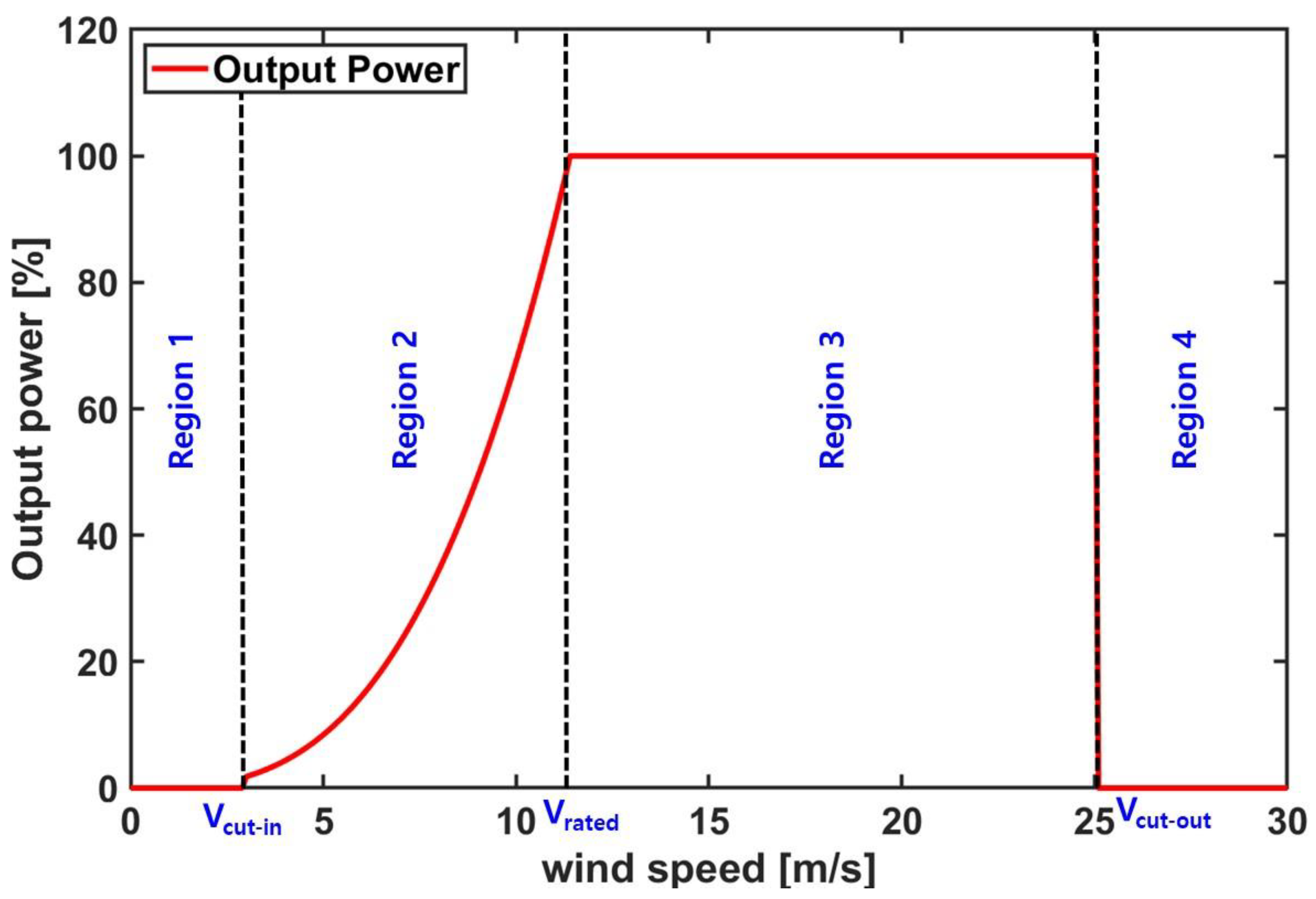
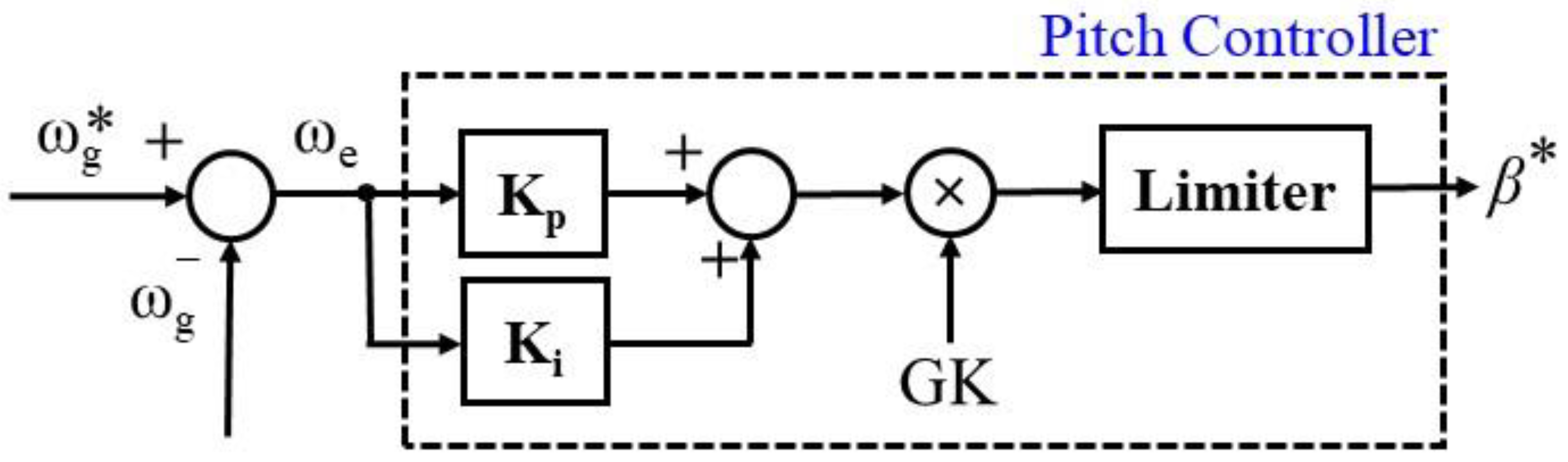
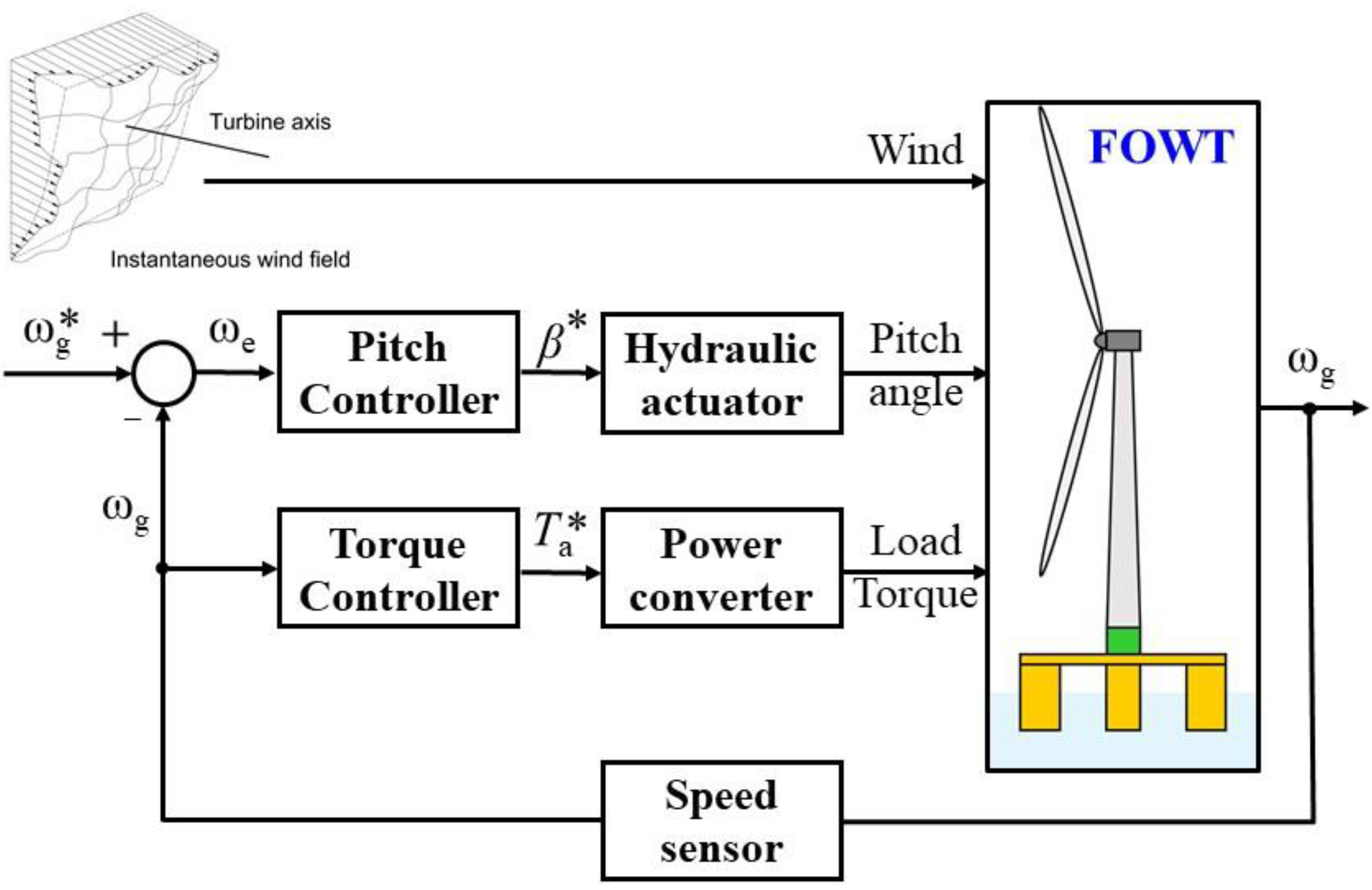
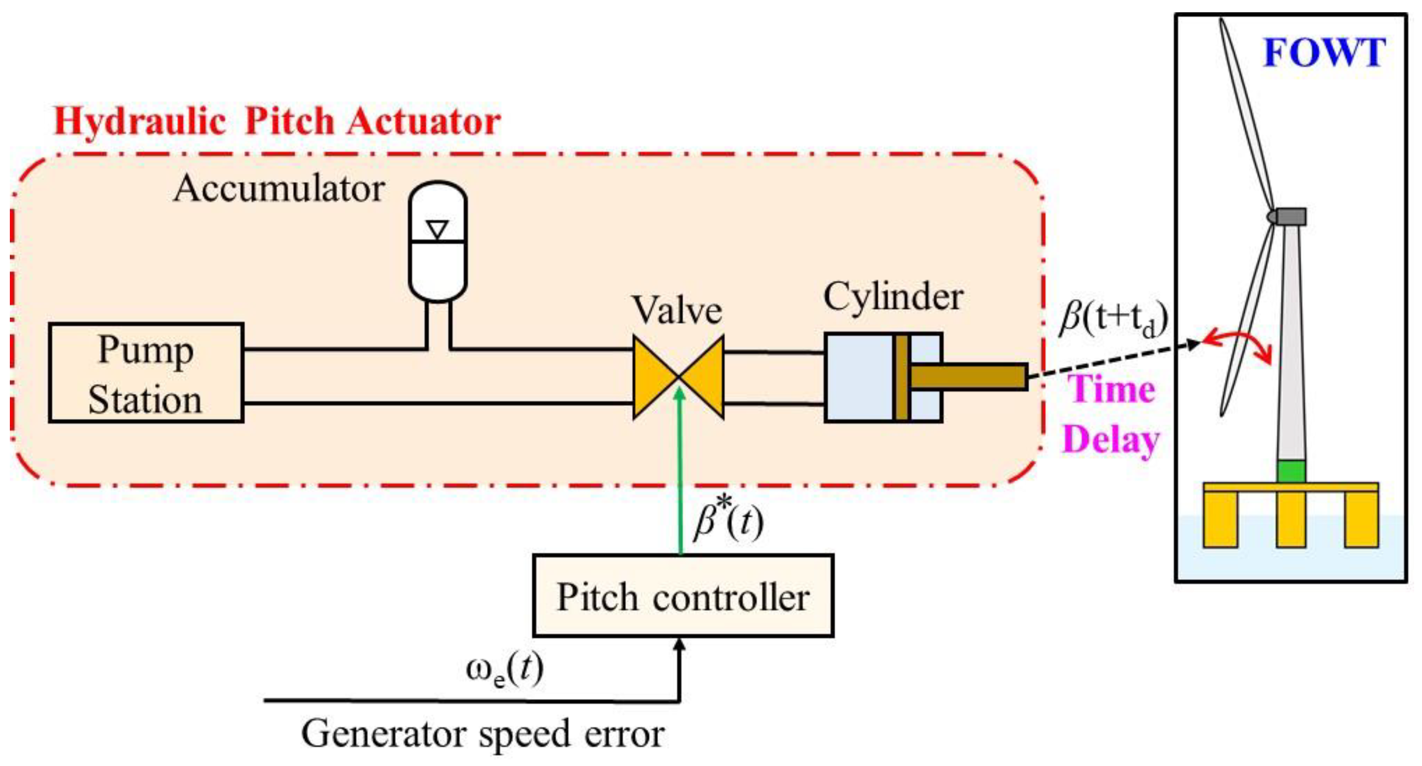
2. Principle and Limitations of Pitch Control Systems

In general, the method for controlling a wind power generation system depends on the input wind speed. In other words, it is necessary to select a controller that is appropriate for the input wind to ensure maximum output and system stability. Figure 1 shows the control regions of a wind power generation system according to the input wind speed.
In Regions 1 and 4, the input wind speed is too slow or too fast, respectively, to generate electricity. Thus, the controller does not operate in these regions. In Region 2, maximum power point tracking (MPPT) control is performed to obtain the maximum output with the changing input wind speed. In the case of MPPT control, in order to convert as much of the aerodynamic input power of the blades as possible into electrical power, the pitch control operates to maximize the efficiency of the turbine. The reference power for MPPT control can be expressed as follows:
P a * = 1 2 π R rotor 2 ρ ( C p ( λ ,   θ ) / λ ) V w 2
In Region 3, because the energy of the input wind speed exceeds the rated capacity of the system, the pitch control operates to prevent the rated capacity from being exceeded. In this region, the rated output is maintained even when the input wind speed changes, by changing the pitch angle. For the same wind speed, adjusting the pitch angle reduces the efficiency of the turbine, which may force a reduction in output. The existing pitch controller adjusts the pitch angle using a PI controller, based on the rotational speed of the generator. Figure 2 shows the configuration of the pitch controller for a floating wind power generation system.
In the case of a floating wind power system, the relative motion of the floating body depends on the PI controller parameter of the pitch controller. That is, unlike the pitch controller of an onshore wind power generation system, for a pitch controller that considers the motion of the platform, the PI gain needs to be tuned. The PI gain of a floating wind power system can be calculated as follows [47]:
K p = C 1 N G [ ( Δ P wind / Δ θ ) ( θ = 0 ) ] G K
K i = C 2 N G [ ( Δ P wind / Δ θ ) ( θ = 0 ) ] G K
[ C 1 C 2 ] = I D Ω 0 ω ϕ n [ 2 ς ϕ ω ϕ n ]
Figure 3 shows the configuration of the control system for a floating wind power generation system. The input variables of the control system of the floating wind power generation system include wind, blade pitch angle, and load torque, and the output variables include the angular velocity of the generator.
The actuator of the pitch controller of a wind power generation system typically uses a hydraulic drive device. Because of the inherent characteristics of a hydraulic drive, a delay is introduced; this delay is longer for larger wind power generation systems. In the case of floating wind power generation systems, with their higher system unit capacities, the delay is an even more important factor. In addition, the relative motion of the floating body from the influence of the pitch controller is increased, and the delay may further increase this motion.
Figure 4 shows the configuration of the pitch controller of a hydraulic-actuator-based floating wind power generation system. The pitch controller calculates the blade pitch angle based on the angular velocity of the generator and changes the pitch angle of the blade using the hydraulic actuator to control it as the reference pitch angle. When the blade pitch angle obtained through the pitch controller is driven using a hydraulic actuator, there is an unavoidable delay (td) introduced, owing to the characteristics of hydraulic actuators. This delay causes a decrease in the output power generated and an increase in the relative motion of the floating body, which can reduce the stability of the system.
Figure 5 shows the output characteristics of a floating wind power generation system according to the delay due to the hydraulic actuator. It is possible to show different delay times because the delay due to the hydraulic actuator can be changed by varying the blade size. It can be seen that the blade control angle varies much more when there is a delay than in the case of ideal control performance. It can likewise be seen that the variability of the platform pitch representing the motion of the floating body increases accordingly. As the magnitude of the delay increases, the responsiveness to the input energy is slowed, and it is confirmed that the variability in the amount of power generated also increases.
Figure 6 details a pair of graphs showing the floating body motion characteristics and power generation characteristics of the floating wind power generation system according to the delay from the hydraulic actuator. First, it can be seen that as the delay due to the hydraulic actuator increases from the ideal case of zero delay, the variability in the floating platform pitch motion increases. This means that in a floating offshore wind power generation system, the delay in the pitch controller response may impair the stability of the floating body. In addition, it can be seen that the delay in response further reduces the average amount of power generated, confirming that the amount generated is reduced as the delay increases. Thus, is it confirmed that for a floating wind power generation system, delays in the pitch controller response reduce both the stability of the floating body and the average amount of power generated.

3. Materials and Methods

3.1. Pitch Control Angle Prediction System with Deep Learning Algorithm

Data prediction studies have been conducted that use various deep learning algorithms in many applications. An algorithm for accurate prediction is constructed by considering various input variables that affect the data to be predicted. Thus, if a control signal capable of compensating for the delay can be predicted by incorporating characteristics of the control signal that may occur as a result of the delay, it may be possible to recover the stability of the floating body and restore the amount of power generated. Therefore, in this study, the input data that affect the existing pitch controller are analyzed, and the delay that may occur from the use of a hydraulic driving device is predicted by applying a deep learning algorithm.
Figure 7 shows the configuration of the proposed pitch controller with the deep learning algorithm applied. The deep learning algorithm predicts the leading blade pitch angle based on the delay occurring in the hydraulic actuator. If the blade pitch angle can be predicted as far in advance as the length of the delay occurring in the hydraulic actuator, the delay can be compensated. This will make it possible to reduce the pitch motion of the platform and compensate for the loss in power generated due to the delay in response to the pitch controller.
In this study, long short-term memory (LSTM)—a deep learning algorithm—was applied to a pitch controller. The LSTM algorithm is derived from the RNN algorithm. Because the LSTM algorithm uses a forget gate and an input gate, it has the advantage that the back-propagation gradient is transmitted well even if the distance from the input data is large. Figure 8 shows a block diagram of the LSTM algorithm.
In the forget gate, past input information is selected. A value between 0 and 1 is used to properly reflect past state information using the sigmoid function: If the value is 0, the information from the previous state is forgotten, and if the value is 1, the information from the previous state is fully remembered. The gate of oblivion can be represented as [47]
f t = σ ( ω x h _ f x t + ω h h _ f h t 1 + b h _ f )
The input gate stores the current input data. Using the hidden state value (ht−1) from the previous step and the current state data, we can calculate the strength and direction of the current data as
i t = σ ( ω x h _ i x t + ω h h _ i h t 1 + b h _ i )
o t = σ ( ω x h _ o x t + ω h h _ o h t 1 + b h _ o )
The LSTM equations reflecting the forget gate and the input gate can be written as
g t = tan h ( ω x h _ g x t + ω h h _ g h t 1 + b h _ g )
c t = f t c t 1 + i t g t
h t = o t tan h ( c t )
Figure 9 shows the correlation matrix between the input data and the prediction data entered into the deep learning algorithm used to construct the pitch controller with the deep learning algorithm. In general, correlation analysis allows the advance prediction of outcome data. The correlation of the data can be confirmed through the colors and numbers in Figure 9; the closer the value is to 1, the higher is the correlation between the input data and the output data. Here, the input variables are the error in the generator’s rotational speed (rpm) and the blade pitch angle, and the predicted variable is the blade pitch angle after the time delay.
As training data, three-hour data of an ideal pitch controller was used. Blade pitch angles used three sets of winds (8 m/s, 11.4 m/s, 15 m/s) at the same crest conditions (Hs = 6 m and Tp = 10 s). For each wind turbulence condition, class-A condition was used. The amount of data in one set consists of 216,000, and the training time for one set is about 5 h. For training data, 80% of the total data was randomly trained, and the remaining 20% of the total data was verified using the tested data. The validation of the learning data for data generation was performed through a model test.
In a deep learning algorithm, a model that predicts output data based on input data is constructed. The mean squared error (MSE) is a model evaluation method for updating the model weights; it is the most commonly used loss method in deep learning algorithms. The loss model used for the model evaluation was as follows:
MSE = 1 N ( Y A Y P ) 2
where Y A is the actual value, Y P is the predicted value, and N is the sample size. The weight update cycle was optimized using the Adam function—an optimizer for KERAS, an advanced gradient descent method. In order to construct the proposed pitch controller with the deep learning algorithm, a neural network was constructed based on the results of the existing ideal pitch controller. The input data were composed based on the error in the generator’s rotational speed (rpm) and the blade pitch angle, as shown in Figure 9, and the prediction was for the blade pitch angle after 2 s and assuming a delay time of 2 s.
Figure 10 shows the actual blade pitch angle after 2 s and the blade pitch angle given by the pitch controller with the LSTM algorithm. It can be seen that the proposed pitch controller follows the actual blade pitch angle after 2 s, confirming that the pitch controller with the deep learning algorithm can compensate even if a delay occurs.

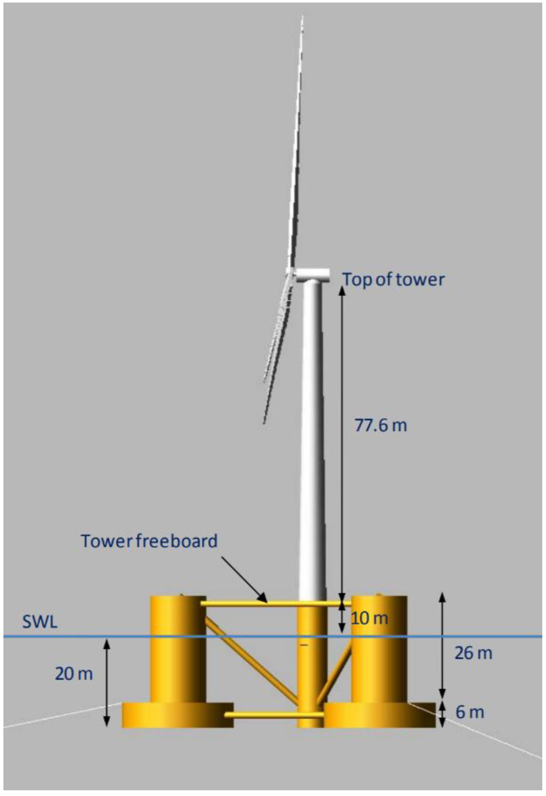
3.2. Setup for Evaluative Simulation

The dynamic analysis of the floating offshore wind power system was performed using the Fatigue, Aerodynamics, Structures, and Turbulence (FAST) v8 model developed by the US National Renewable Energy Laboratory (NREL) [48]. The FAST v8 model was run using MATLAB/Simulink. The numerical analysis was performed by configuring the ideal pitch controller (labeled “ideal”), the pitch controller reflecting the delay due to the hydraulic actuator (“delay”), and the pitch controller with the LSTM algorithm (“predict”). An NREL five-megawatt-class turbine was used as the wind turbine [49], and an OC4 semisubmersible platform was used as the floating platform [50]. Figure 11 shows the target offshore wind power system.
The performance of the floating offshore wind power generation system with each pitch controller was assessed using the same assumed environmental input conditions. The ideal pitch controller allowed the blade pitch control angle determined by the pitch controller to operate without a time delay. The pitch controller that includes the delay due to the hydraulic actuator was operated by reflecting a delay time of 2 s to the blade pitch control angle determined by the pitch controller. The pitch controller based on the proposed deep learning algorithm predicted the blade pitch control angle by applying the LSTM algorithm. The blade pitch control angle predicted the blade pitch angle after 2 s, the delay time of the hydraulic actuator. As the input environmental conditions, Class A was applied for turbulence intensity at a rated wind speed of 11.4 m/s, and a Pierson-Moskowitz (PM) spectrum of Hs = 6 m and Tp = 10 s was applied. For the realization of the blue spectrum, the total simulation time was 3 h.

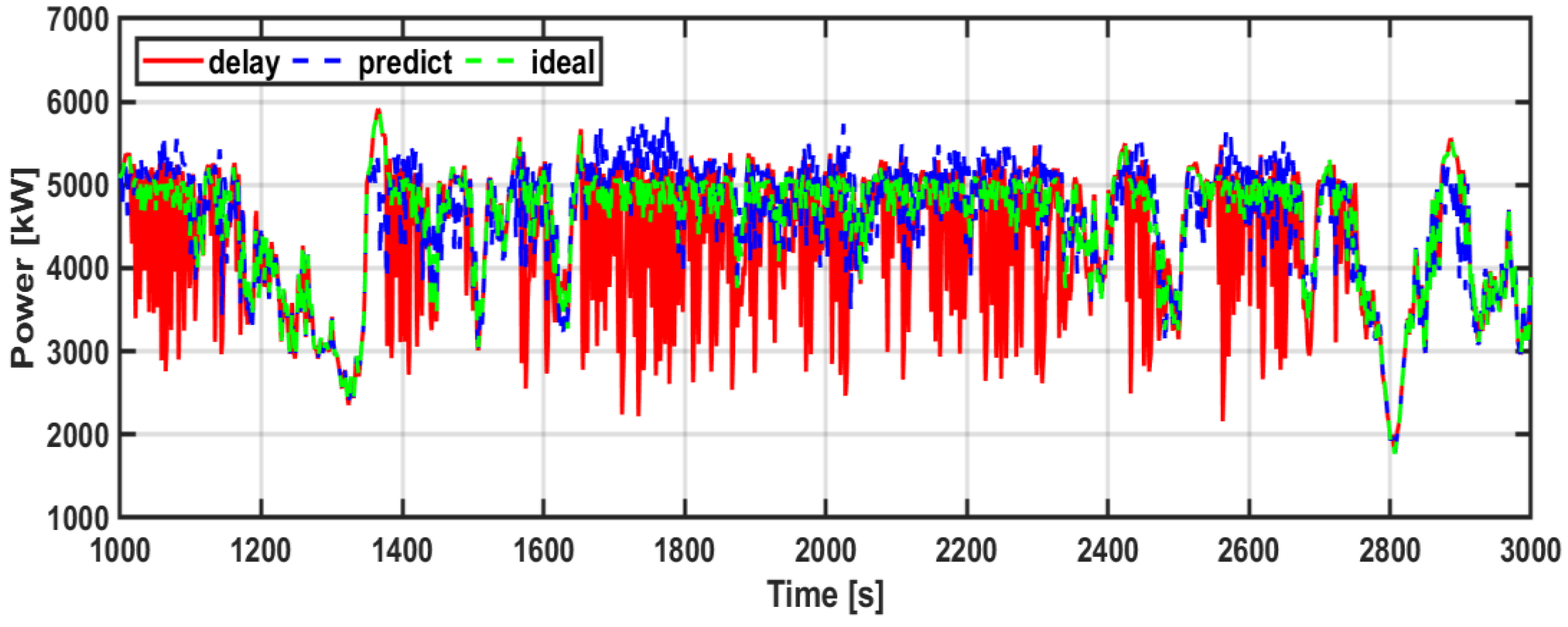
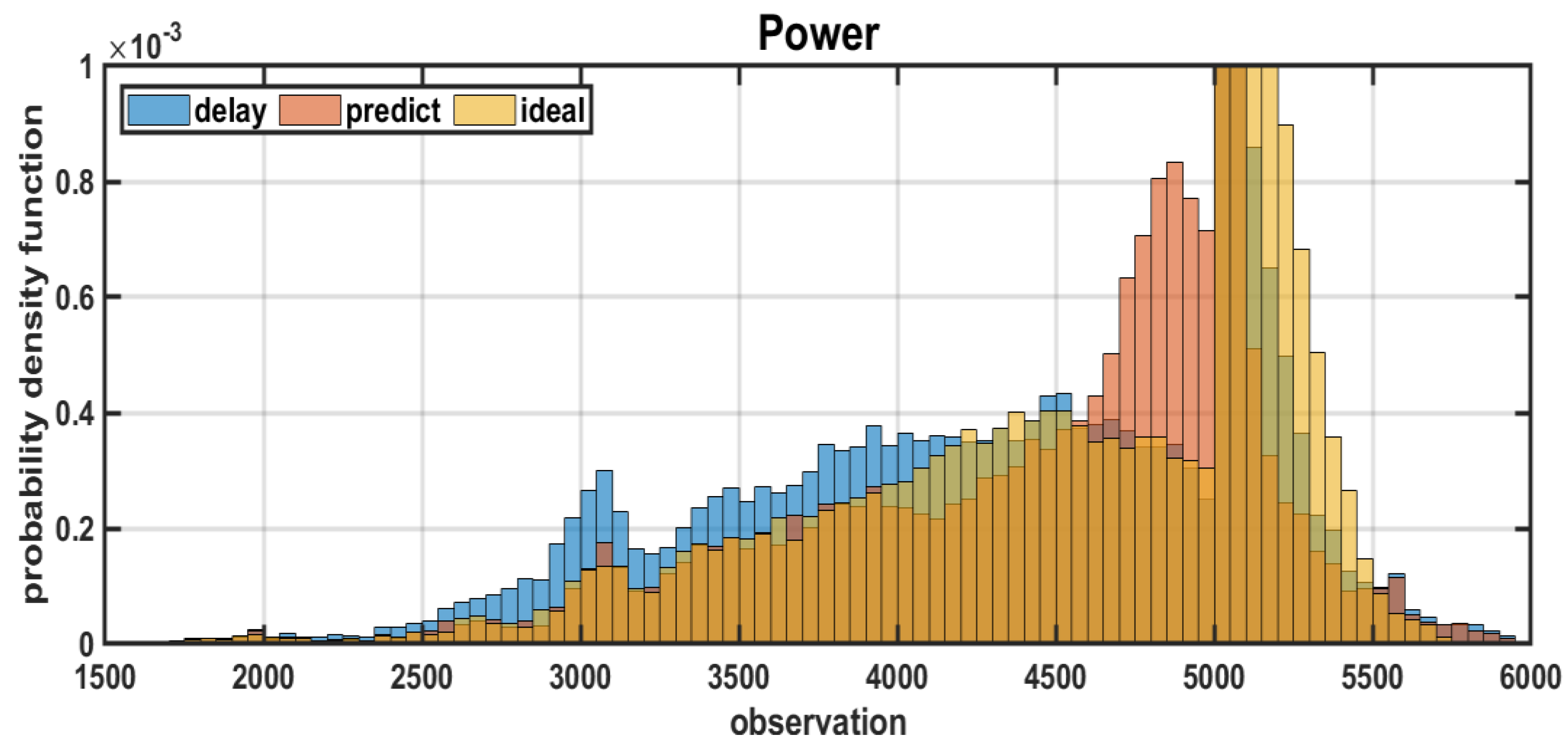
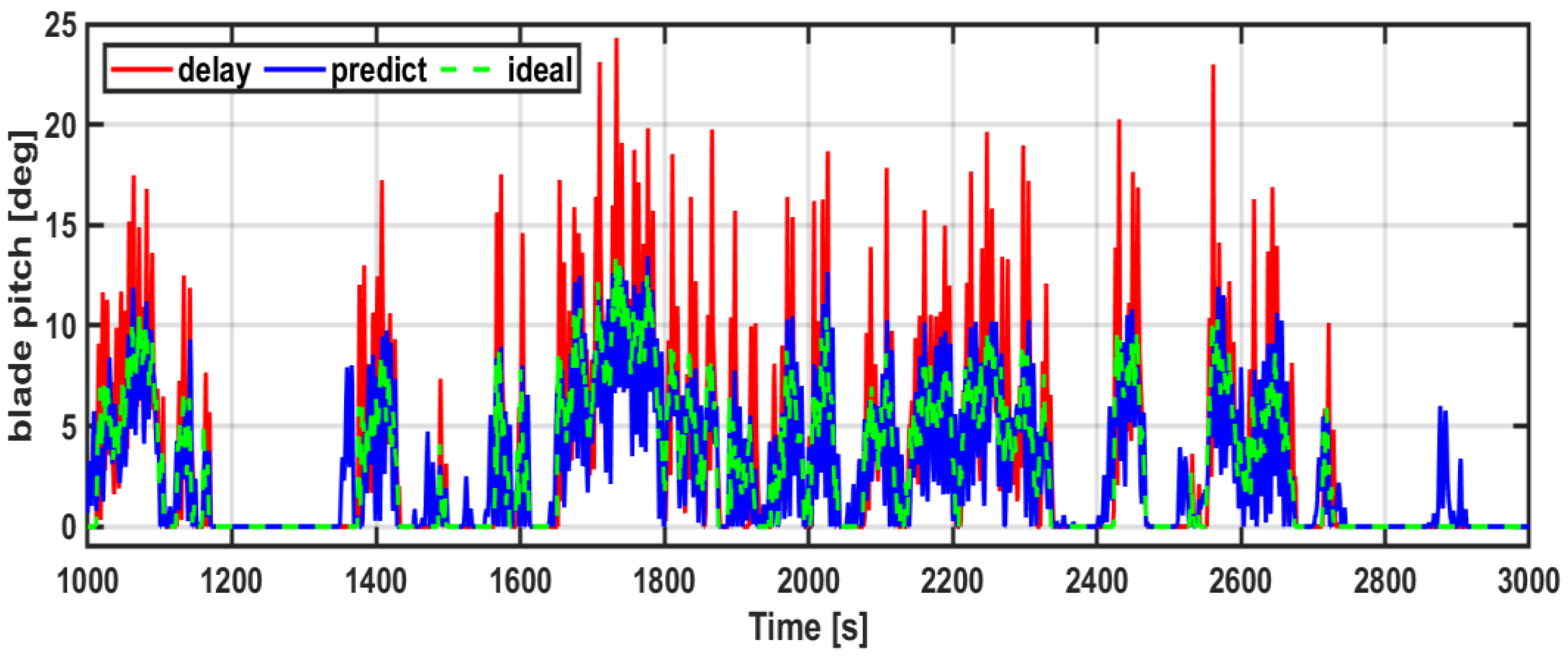
4. Results and Discussion

Figure 12 shows the output power generated under the three pitch controllers. It can be seen that the ideal pitch controller exhibits the least variation in the output power generated; this is because there is no delay in the response of the blade pitch angle. The output power variability with the pitch controller that reflects the delay due to the hydraulic actuator is substantially greater, owing to the delay. Although the proposed pitch controller has a delay because it reflects the characteristics of the hydraulic actuator, it can be seen that it reduces the output power variability; this is because the blade pitch control angle is predicted by the deep learning algorithm.
Figure 13 shows the same data in histogram form of the output power generated under the three pitch controllers. As in Figure 12, it is seen that the output power generated under the ideal pitch controller remains close to 5 MW. However, because turbulent wind conditions are considered, lower power generation values are also observed. In the case of the pitch controller that reflects the delay due to the hydraulic actuator, it can be seen that the lower power generation values appear more frequently than under the ideal pitch controller. In the case of the proposed pitch controller, the distribution of the output power generated is similar to that of the ideal pitch controller. Thus, it is confirmed that the power generation output can be compensated for by the proposed pitch controller even if a delay occurs.
Figure 14 shows the blade pitch angle under the three pitch controllers. It can be seen that, unlike the ideal pitch controller, the pitch controller that reflects the delay due to the hydraulic actuator drives dramatic changes in the blade pitch angle, owing to the delay in response. This occurs because the change in the angular velocity of the generator increases, and the motion of the platform increases. Because the response of the blade pitch angle is delayed, the output power generation will also be markedly reduced because the blade pitch angle is below the wind speed rating in the turbulent wind speed condition. However, the pitch controller with the deep learning algorithm can obtain a blade pitch angle similar to that given by the ideal pitch controller even with the delay in response. Thus, under the proposed method, the output power generation was not substantially reduced even with the delay in response by the blade pitch angle, because of the prediction of the blade pitch control angle.
Figure 15 shows the same data in histogram form of the blade pitch angle under the three pitch controllers. The histogram for the proposed pitch controller is similar to that of the ideal pitch controller. However, under the pitch controller that reflects the delay due to the hydraulic actuator, the blade pitch angle exhibits marked fluctuation. Although the proposed pitch controller also differs from the ideal pitch controller in the frequencies of low pitch angles, it can be seen that the variability in the blade pitch angle with the delay in response is substantially reduced. As a result, there will not be a major reduction in the power generation output.
In addition to output power generation, the motion of the floating body is an important concern for a floating offshore wind power system. Figure 16 shows the floating body pitch motion under the three pitch controllers. It can be seen that the pitch motion of the floating body is greater under the pitch controller that reflects the delay due to the hydraulic actuator than under the ideal pitch controller; this is because of the delay in response of the blade pitch angle. Under the proposed pitch controller, however, the pitch motion of the floating body is less than that under the ideal pitch controller. The histograms shown in Figure 17 confirm that the pitch controller that reflects the delayed response can substantially increase the pitch motion of the floating body, whereas the proposed pitch controller can reduce the pitch motion of the floating body. This demonstrates that the proposed pitch controller can reduce floating body motion even in the presence of a delay in response.
Figure 18 shows a comparison of the averages and standard deviations of four output variables for the three pitch controllers. First, in terms of the amount of power generated, it can be seen that the average under the pitch controller that reflects the delay due to the hydraulic actuator is approximately 5% less than that under the ideal pitch controller, with a standard deviation 17% greater. Because the proposed pitch controller overcomes the delay in response by using the deep learning algorithm, the average power generation under the proposed pitch controller is not less than that under the ideal pitch controller, although the standard deviation is approximately 5% greater. Next, in terms of the bending moment received by the blade, the standard deviation under the pitch controller that reflects the delay due to the hydraulic actuator is much greater than that under the ideal pitch controller; this effect is due to the delay in response to the blade control angle. Finally, in terms of the pitch motion of the floating body, the standard deviation under the pitch controller that reflects the delay is approximately 42% greater than that under the ideal pitch controller, whereas that under the proposed pitch controller is approximately 29% less. These findings demonstrate that the pitch controller with the deep learning algorithm can compensate for the delay in response due to the hydraulic actuator, as reflected in the improvement in performance of the motion response of the floating body.
Figure 19 compares the performance of the proposed blade pitch controller under various wind conditions. Since output power and platform pitch motion are important performance indicators, they were compared while changing wind conditions. Similar to the performance shown in Figure 18, it can be confirmed that the proposed blade pitch controller shows the same performance even when the input wind conditions are changed. Since the proposed blade pitch controller was trained based on the input data with significant changes, it was confirmed that the performance was not significantly affected even if the input wind conditions were changed. In other words, it was confirmed that the proposed blade pitch controller is possible under various conditions.

5. Conclusions

The time delay that can only be caused by the hydraulic actuator increases as the turbine capacity increases and the length of the blade increases. This paper has proposed an advanced pitch controller designed to compensate for the delay in response due to the use of hydraulic actuators in a floating offshore wind power generator through the incorporation of a deep learning algorithm. The pitch controller based on a deep learning algorithm can compensate for the time delay because it derives the blade pitch control angle by predicting the time delay occurring in the hydraulic actuator in advance. The proposed method increased the average power generation by approximately 5% over that of the pitch controller that reflects the delay in response and reduced the standard deviation of the pitch motion of the floating body by approximately 50%, thereby demonstrating that the proposed pitch controller can compensate for the response delay due to the use of a hydraulic actuator. It can be confirmed that the proposed pitch controller exhibits the same performance even when the input wind speed conditions change. The proposed pitch controller verified under various conditions will be applied to numerical model tests and actual systems in the future.

Funding

This research received no external funding.

Institutional Review Board Statement

Not applicable.

Informed Consent Statement

Not applicable.

Data Availability Statement

Not applicable.

Acknowledgments

This research was supported by a grant from National R&D Project “Development of Predictive Maintenance Technology for Floating Offshore Wind Power Systems Based on Digital Twin Technology (PNS3910)” funded by the Ministry of Trade, Industry and Energy (MOTIE) and the Korea Energy Technology Evaluation and Planning (KETEP).

Conflicts of Interest

The author declares no conflict of interest.

Abbreviations

The following abbreviations are used in this manuscript:
P a Rotor power (Mechanical power)
C p Turbine coefficient
R r o t o r length of rotor blades
ρ Density of air
λ Tip speed ratio
V w Wind speed
Ω r Rotational speed of rotor
T a Mechanical torque
λ Tip speed ratio
NGear ratio
I D Drivetrain inertia
Ω 0 Rated low-speed shaft rotational speed
ω ϕ n Natural frequency of PI controller
ς ϕ Damping ratio of PI controller
θ Rotor-collective blade-pitch angle
θ k Blade-pitch angle which sensitivity has doubled
G K Gain-correction factor
ω g Rotational speed of generator
ω g * Reference rotational speed of generator
K p Proportional gain of PI controller
K i Integral gain of PI controller
β * Reference blade pitch angle

References

  1. Ohlenforst, K.; Sawyer, S.; Dutton, A.; Backwel, B.; Fiestas, R.; Lee, J.; Qiao, L.; Zhao, F.; Balachandran, N. GWEC Global Wind Report 2018; Technical Report; Global Wind Energy Council (GWEC): Brussels, Belgium, 2019. [Google Scholar]
  2. Jonkman, J.M. Dynamics Modeling and Loads Analysis of an Offshore Floating Wind Turbine; Technical Report NREL/TP-500-41958; National Renewable Energy Laboratory (NREL): Golden, CO, USA, 2007. [Google Scholar] [CrossRef] [Green Version]
  3. Cruciani, M. The expansion of offshore wind power in the North Sea: A strategic opportunity for the European Union. Econ. Policy Energy Environ. 2019, 1, 5–28. [Google Scholar] [CrossRef]
  4. International Electrotechnical Commission Technical Committee 88: Wind Turbines. Wind Turbines—Part 3: Design Requirements for Offshore Wind Turbines; International Standard IEC 61400-3:2009; International Electrotechnical Commission: Geneva, Switzerland, 2009. [Google Scholar]
  5. Skaare, B.; Hanson, T.D.; Nielsen, F.G. Importance of control strategies on fatigue life of floating wind turbines. In Proceedings of the ASME 2007 26th International Conference on Offshore Mechanics and Arctic Engineering, San Diego, CA, USA, 10–15 June 2007; pp. 493–500. [Google Scholar] [CrossRef]
  6. Soriano, L.; Yu, W.; Rubio, J.d.J. Modeling and control of wind turbine. Math. Probl. Eng. 2013, 2013, 982597. [Google Scholar] [CrossRef]
  7. Suryanarayanan, S.; Dixit, A. On the dynamics of the pitch control loop in horizontal-axis large wind turbines. In Proceedings of the 2005 American Control Conference, Portland, OR, USA, 8–10 June 2005; Volume 1, pp. 686–690. [Google Scholar] [CrossRef]
  8. Cross, P.; Ma, X. Nonlinear system identification for model-based condition monitoring of wind turbines. Renew. Energy 2014, 71, 166–175. [Google Scholar] [CrossRef] [Green Version]
  9. Mérida, J.; Aguilar, L.T.; Dávila, J. Analysis and synthesis of sliding mode control for large scale variable speed wind turbine for power optimization. Renew. Energy 2014, 71, 715–728. [Google Scholar] [CrossRef]
  10. Boukhezzar, B.; Lupu, L.; Siguerdidjane, H.; Hand, M. Multivariable control strategy for variable speed, variable pitch wind turbines. Renew. Energy 2007, 32, 1273–1287. [Google Scholar] [CrossRef]
  11. Wu, D.; Wang, Z. Modeling and design of control system for variable speed wind turbine in all operating region. Int. J. Syst. Appl. Eng. Dev. 2007, 3, 62–68. [Google Scholar]
  12. Duong, M.Q.; Grimaccia, F.; Leva, S.; Mussetta, M.; Ogliari, E. Pitch angle control using hybrid controller for all operating regions of SCIG wind turbine system. Renew. Energy 2014, 70, 197–203. [Google Scholar] [CrossRef]
  13. Yin, X.; Lin, Y.; Li, W.; Gu, Y.; Wang, X.; Lei, P. Design, modeling and implementation of a novel pitch angle control system for wind turbine. Renew. Energy 2015, 81, 599–608. [Google Scholar] [CrossRef]
  14. Oh, K.; Park, J.; Lee, J.; Lee, J. Implementation of a torque and a collective pitch controller in a wind turbine simulator to characterize the dynamics at three control regions. Renew. Energy 2015, 79, 150–160. [Google Scholar] [CrossRef]
  15. Bossoufi, B.; Karim, M.; Lagrioui, A.; Taoussi, M.; Derouich, A. Observer back stepping control of DFIG-generators for wind turbines variable-speed: FPGA-based implementation. Renew. Energy 2015, 81, 903–917. [Google Scholar] [CrossRef]
  16. Larsen, T.J.; Hanson, T.D. A method to avoid negative damped low frequent tower vibrations for a floating, pitch controlled wind turbine. J. Phys. Conf. Ser. 2007, 75, 012073. [Google Scholar] [CrossRef]
  17. Salma, T.; Yokeeswaran, R. Pitch control of DFIG based wind energy conversion system for maximum power point tracking. Int. J. Adv. Res. Electr. Electron. Instrum. Eng. 2013, 2, 6373–6381. [Google Scholar]
  18. Fakharzadeh, A.; Jamshidi, F.; Talebnezhad, L. New approach for optimizing energy by adjusting the trade-off coefficient in wind turbines. Energy Sustain. Soc. 2013, 3, 19. [Google Scholar] [CrossRef] [Green Version]
  19. Kim, Y.; Chung, I.; Moon, S. Tuning of the PI controller parameters of a PMSG wind turbine to improve control performance under various wind speeds. Energies 2015, 8, 1406–1425. [Google Scholar] [CrossRef] [Green Version]
  20. Silva, G.J.; Datta, A.; Bhattacharyya, S.P. New results on the synthesis of PID controllers. IEEE Trans. Automat. Contr. 2002, 47, 241–252. [Google Scholar] [CrossRef]
  21. Gao, R.; Gao, Z. Pitch control for wind turbine systems using optimization, estimation and compensation. Renew. Energy 2016, 91, 501–515. [Google Scholar] [CrossRef]
  22. Wang, J.; Tse, N.; Gao, Z. Synthesis on PI-based pitch controller of large wind turbines generator. Energy Convers. Manag. 2011, 52, 1288–1294. [Google Scholar] [CrossRef]
  23. Perng, J.; Chen, G.; Hsieh, S. Optimal PID controller design based on PSO-RBFNN for wind turbine systems. Energies 2014, 7, 191–209. [Google Scholar] [CrossRef] [Green Version]
  24. Fadare, D.A. The application of artificial neural networks to mapping of wind speed profile for energy application in Nigeria. Appl. Energy 2010, 87, 934–942. [Google Scholar] [CrossRef]
  25. Asrari, A.; Wu, T.X.; Ramos, B. A hybrid algorithm for short-term solar power prediction—Sunshine State case study. IEEE Trans. Sustain. Energy 2017, 8, 582–591. [Google Scholar] [CrossRef]
  26. Mendonça de Paiva, G.; Pires Pimentel, S.; Pinheiro Alvarenga, B.; Gonçalves Marra, E.; Mussetta, M.; Leva, S. Multiple site intraday solar irradiance forecasting by machine learning algorithms: MGGP and MLP neural networks. Energies 2020, 13, 3005. [Google Scholar] [CrossRef]
  27. Hu, J.; Wang, J.; Zeng, G. A hybrid forecasting approach applied to wind speed time series. Renew. Energy 2013, 60, 185–194. [Google Scholar] [CrossRef]
  28. Costa, A.; Crespo, A.; Navarro, J.; Lizcano, G.; Madsen, H.; Feitosa, E. A review on the young history of the wind power short-term prediction. Renew. Sustain. Energy Rev. 2008, 12, 1725–1744. [Google Scholar] [CrossRef] [Green Version]
  29. Khan, M.; Liu, T.; Ullah, F. A new hybrid approach to forecast wind power for large scale wind turbine data using deep learning with TensorFlow framework and principal component analysis. Energies 2009, 12, 2229. [Google Scholar] [CrossRef] [Green Version]
  30. Mujeeb, S.; Alghamdi, T.A.; Ullah, S.; Fatima, A.; Javaid, N.; Saba, T. Exploiting deep learning for wind power forecasting based on big data analytics. Appl. Sci. 2019, 9, 4417. [Google Scholar] [CrossRef] [Green Version]
  31. Fu, J.; Chu, J.; Guo, P.; Chen, Z. Condition monitoring of wind turbine gearbox bearing based on deep learning model. IEEE Access 2019, 7, 57078–57087. [Google Scholar] [CrossRef]
  32. Li, M.; Wang, S.; Fang, S.; Zhao, J. Anomaly detection of wind turbines based on deep small-world neural network. Appl. Sci. 2020, 10, 1243. [Google Scholar] [CrossRef] [Green Version]
  33. Jie, W.; Jingchun, C.; Lin, Y.; Wenliang, W.; Jian, D. Pitch control of wind turbine based on deep neural network. In IOP Conference Series: Earth and Environmental Science; IOP Publishing: Changchun, China, 2020; Volume 619, p. 012034. [Google Scholar]
  34. Zhang, Z.; Zhang, D.; Qiu, R.C. Deep reinforcement learning for power system applications: An overview. CSEE J. Power Energy Syst. 2019, 6, 213–225. [Google Scholar]
  35. Lin, Z.; Liu, X. Assessment of wind turbine aero-hydroservo-elastic modelling on the effects of mooring line tension via deep learning. Energies 2020, 13, 2264. [Google Scholar] [CrossRef]
  36. Sierra-Garcia, J.E.; Santos, M. Exploring reward strategies for wind turbine pitch control by reinforcement learning. Appl. Sci. 2020, 10, 7462. [Google Scholar] [CrossRef]
  37. Sierra, J.E.; Santos, M. Modelling engineering systems using analytical and neural techniques: Hybridization. Neurocomputing 2018, 271, 70–83. [Google Scholar] [CrossRef]
  38. Sierra-Garcia, J.E.; Santos, M. Switched learning adaptive neuro-control strategy. Neurocomputing 2021, 452, 450–464. [Google Scholar] [CrossRef]
  39. Chavero-Navarrete, E.; Trejo-Perea, M.; Jauregui-Correa, J.C.; Carrillo-Serrano, R.V.; Ronquillo-Lomeli, G.; Rios-Moreno, J.G. Hierarchical pitch control for small wind turbines based on fuzzy logic and anticipated wind speed measurement. Appl. Sci. 2020, 10, 4592. [Google Scholar] [CrossRef]
  40. Moodi, H.; Bustan, D. Wind turbine control using TS systems with nonlinear consequent parts. Energy 2019, 172, 922–931. [Google Scholar] [CrossRef]
  41. Ngo, Q.V.; Chai, Y.; Nguyen, T.T. The fuzzy-PID based-pitch angle controller for small-scale wind turbine. Int. J. Power Electron. Drive Syst. 2020, 11, 135. [Google Scholar] [CrossRef] [Green Version]
  42. Iqbal, A.; Ying, D.; Saleem, A.; Hayat, M.A.; Mehmood, K. Efficacious pitch angle control of variable-speed wind turbine using fuzzy based predictive controller. Energy Rep. 2020, 6, 423–427. [Google Scholar] [CrossRef]
  43. Sitharthan, R.; Karthikeyan, M.; Sundar, D.S.; Rajasekaran, S. Adaptive hybrid intelligent MPPT controller to approximate effectual wind speed and optimal rotor speed of variable speed wind turbine. ISA Trans. 2020, 96, 479–489. [Google Scholar] [CrossRef]
  44. Rubio, P.M.; Quijano, J.F.; López, P.Z. Intelligent control for improving the efficiency of a hybrid semi- submersible platform with wind turbine and wave energy converters. Rev. Iberoam. Automa Tica E Inf. Tica Ind. 2019, 16, 480–491. [Google Scholar]
  45. Wang, L.; Zuo, S.; Song, Y.D.; Zhou, Z. Variable torque control of offshore wind turbine on spar floating platform using advanced RBF neural network. Abstr. Appl. Anal. 2014, 2014, 903493. [Google Scholar] [CrossRef] [Green Version]
  46. Dahbi, A.; Nait-Said, N.; Nait-Said, M. A novel combined MPPT-pitch angle control for wide range variable speed wind turbine based on neural network. Int. J. Hydrogen Energy 2016, 41, 9427–9442. [Google Scholar] [CrossRef]
  47. Cheng, J.; Dong, L.; Lapata, M. Long short-term memory-networks for machine reading. arXiv 2016, arXiv:1601.06733. [Google Scholar]
  48. Jonkman, J.M.; Buhl, M.L., Jr. FAST User’s Guide; National Renewable Energy Laboratory: Golden, CO, USA, 2005; Volume 365, p. 366. [Google Scholar]
  49. Jonkman, J.; Butterfield, S.; Musial, W.; Scott, G. Definition of a 5-MW Reference Wind Turbine for Offshore System Development; Technical Report NREL/TP-500-38060; National Renewable Energy Laboratory (NREL): Golden, CO, USA, 2009. [Google Scholar] [CrossRef] [Green Version]
  50. Robertson, A.; Jonkman, J.; Masciola, M.; Song, H.; Goupee, A.; Coulling, A.; Luan, C. Definition of the Semisubmersible Floating System for Phase II of OC4; Technical Report NREL/TP-5000-60601; National Renewable Energy Laboratory (NREL): Golden, CO, USA, 2014. [Google Scholar] [CrossRef] [Green Version]
Figure 1. Wind turbine output characteristic curve according to wind speed.
Energies 15 03136 g001
Figure 2. Pitch controller configuration for controlling rated output.
Energies 15 03136 g002
Figure 3. Diagram of overall control system for a floating offshore wind turbine (FOWT) system.
Energies 15 03136 g003
Figure 4. Configuration of pitch controller based on hydraulic actuator.
Energies 15 03136 g004
Figure 5. Results of step changes in wind speed according to the delay in the pitch controller response: blade pitch angle, platform (plat.) pitch, output power.
Energies 15 03136 g005
Figure 6. Characteristics according to delay time (s) of hydraulic actuator: (a) Standard deviation (std) of platform pitch motion of floating body; (b) average amount of power generated.
Energies 15 03136 g006
Figure 7. Configuration of the proposed pitch controller with deep learning algorithm. (LSTM, long short-term memory).
Energies 15 03136 g007
Figure 8. Block diagram of LSTM algorithm.
Energies 15 03136 g008
Figure 9. Data correlation matrix used to drive the deep learning algorithm.
Energies 15 03136 g009
Figure 10. Comparison of actual and predicted values for application of delay compensation. (Ang., angle.).
Energies 15 03136 g010
Figure 11. Design of floating wind system with OC4 semisubmersible platform [50].
Energies 15 03136 g011
Figure 12. Output power of floating offshore wind turbine by pitch controller.
Energies 15 03136 g012
Figure 13. Histogram of output power of floating offshore wind turbine by pitch controller.
Energies 15 03136 g013
Figure 14. Blade pitch angle of floating offshore wind turbine by pitch controller.
Energies 15 03136 g014
Figure 15. Histogram of blade pitch angle of floating offshore wind turbine by pitch controller.
Energies 15 03136 g015
Figure 16. Platform pitch angle of floating offshore wind turbine by pitch controller.
Energies 15 03136 g016
Figure 17. Histogram of platform pitch angle of floating offshore wind turbine by pitch controller.
Energies 15 03136 g017
Figure 18. (a) Average values and (b) standard deviations of four output variables according to pitch controller. (power, rotational speed, bending moment, platform pitch).
Energies 15 03136 g018
Figure 19. Average values of (a) power and (b) platform pitch and standard deviations of (c) power and (d) platform pitch according to pitch controller.
Energies 15 03136 g019
Publisher’s Note: MDPI stays neutral with regard to jurisdictional claims in published maps and institutional affiliations.

