Article

Verification Platform of SOC Estimation Algorithm for Lithium-Ion Batteries of Electric Vehicles

Tsinghua Shenzhen International Graduate School, Tsinghua University, Shenzhen 518055, China
*
Author to whom correspondence should be addressed.
Energies 2022, 15(9), 3221; https://doi.org/10.3390/en15093221
Submission received: 18 March 2022 / Revised: 17 April 2022 / Accepted: 26 April 2022 / Published: 28 April 2022

Abstract

:
As one of the core technologies of electric vehicles (EVs), the state of charge (SOC) estimation algorithm of lithium-ion batteries is directly related to the performance of the battery management system (BMS). Before EVs are put into the market, the SOC estimation algorithm must be tested and verified to ensure the reliability of the BMS and the safe operation of EVs. Therefore, this paper establishes a lithium-ion batteries’ SOC estimation algorithm verification platform for the comprehensive performance evaluation and verification of the new SOC estimation algorithm. In addition, there are two schemes, including real-time SOC estimation verification and offline SOC estimation verification can be selected, which improve the reliability and efficiency of verification. Firstly, the design idea of the verification platform (the research and development purpose, functional requirements, and the overall design scheme) is introduced in detail. Secondly, the modular design idea is used to design the hardware structure of the verification platform, which mainly includes the BMS host module, BMS slave module, battery charger module, and electronic load module. Finally, the software system, including the communication architecture, the SOC reference standard and evaluation indexes of the algorithm, and the upper computer function and implementation is designed to realize the functions of the verification platform.

1. Introduction

The state of charge (SOC) of lithium-ion batteries is an important parameter of the battery management system (BMS) of electric vehicles (EVs), which is a direct response to the battery power [1,2]. On the one hand, it provides important information for the drivers, and on the other hand, it provides an important basis for the management and maintenance of the battery pack. Accurate SOC estimation is the basis for realizing other functions of BMSs, such as preventing batteries from over-charging or over-discharging and judging the equalization effect of the batteries, etc. It can be seen, that the accuracy of the SOC estimation will affect the implementation effect of other functions of BMSs. As one of the core technologies of EVs, the performance of the SOC estimation strategy is directly related to the advantages and disadvantages of the BMS [3,4,5]. Therefore, before EVs are put into the market, the SOC estimation method of the BMS must be tested and verified to ensure the stability and reliability of the BMS and the safe operation of EVs. At present, the performance of the new SOC estimation method is mainly tested and verified when the EVs are actually in operation, which is obviously inefficient and unsafe [6,7]. Therefore, it is necessary to establish a verification platform in the laboratory to simulate the real state of the battery system in the actual operation of the EVs and improve the efficiency and reliability of the verification of the new SOC estimation method. Through consulting the literature, it can be found that most scholars in the battery field focus on the optimization and improvement of the battery SOC estimation method, but there is little research on the verification platform of the battery SOC estimation algorithm.
The battery cell SOC estimation algorithms can be divided into two estimation methods according to whether it is based on the battery model. The estimation methods without a battery model are mostly traditional and simple estimation methods, including the open-circuit voltage method, discharge experiment method, and ampere-hour integration method. The estimation methods based on the battery model mainly include the Kalman filter, state observer, particle filter, and the neural network method. Common battery models include the electric chemical model, equivalent circuit model, and black-box model. Moreover, the battery pack SOC estimation methods are mainly divided into three categories. (1) The battery pack is regarded as a battery cell with high voltage and large capacity so that the battery cell SOC estimation methods can be directly applied to the battery pack. (2) The second method focuses on the changes and inconsistencies between battery cells; the battery pack SOC is calculated by probability fusion methods, such as the average method, special cell method, and filtering method. (3) The data-driven method is used to find the nonlinear relationship between the measurable variables and the SOC to estimate the battery pack SOC, such as the neural network, support vector machine, Gaussian process regression, etc. The research on the SOC estimation of a battery cell and battery pack has been relatively in-depth, and the research status of the battery SOC estimation algorithm verification platform is described in detail as follows.
Guangjie Sheng established a test and verification system for the SOC estimation method of batteries of new energy vehicles [8], which is a laboratory test platform to simulate various working conditions and environments that are actually used in EVs, including the environment simulation box, battery charge, and discharge test system, with the upper computer and battery management system to be tested. The battery charge and discharge test system simulate various working conditions of the batteries; the environment simulation box simulates the use environment of the battery and management system, and the upper computer monitors the test data of the battery management system to be tested. The battery charge and discharge test system is used to test and verify the battery SOC estimation strategy in the laboratory environment, reduce the test time of real vehicle verification and improve the verification efficiency, but the reference standard of the SOC and the comprehensive evaluation indices of the estimation strategy are not mentioned. Guo et al. invented a verification and evaluation method and device of battery SOC estimation algorithm [9], which pre-stores the open-circuit voltage (OCV) and SOC corresponding relationship curve of the battery before charging or discharging the battery to obtain the SOC reference value, calculates the battery SOC value using the SOC algorithm to be verified, records the operation time of the SOC algorithm, and determines the accuracy of the SOC estimation algorithm to be verified and evaluated based on the comparison between the SOC estimation value and the SOC reference value. Finally, the SOC estimation method to be verified is evaluated based on the operation time and estimation accuracy. This method selects the corresponding relationship of OCV and SOC to obtain the SOC reference value. It takes a long time to obtain the reference SOC, which leads to low verification efficiency. Moreover, this method only considers the verification of the battery cell SOC estimation method and ignores the verification and evaluation of the battery pack SOC estimation method.
Guo et al. took SpeedGoat as the platform and real-time workshop as the automatic code generation tool, established the model with chip computing ability, carried out the hardware-in-the-loop (HIL) simulation test, and thus the bench experiment of the power battery module was built to verify and test the SOC algorithm [10]. However, there is no detailed description of the hardware structure and software system design of the power battery bench experiment. He et al. built a battery cell level HIL system to verify the SOC estimation of the embedded battery algorithm. They selected two different representative batteries to illustrate the verification and development process of the SOC estimation algorithm. The built battery cell level HIL system can verify and evaluate the accuracy of the developed SOC estimation algorithm, accelerate the improvement and optimization of the estimation algorithm, and provide valuable data and experience for reducing the development time and cost of EVs in the future [11]. However, the disadvantage of the HIL system is that it only considered the battery cell level without considering the verification and evaluation of the SOC estimation algorithm of the battery pack level. Zhang et al. studied the battery pack SOC estimation method based on the adaptive extended Kalman filter algorithm, constructed a HIL platform based on xPC Target, and verified and evaluated the SOC estimation algorithm of the battery pack [12]. Their focus is still on the in-depth research and improvement of the battery SOC estimation algorithm, but the research and introduction of algorithm verification platforms are very few.
Indeed, the research on high-precision and high-performance SOC estimation methods of a battery cell and battery pack is very important for the BMS, but the research and development of the SOC estimation algorithm verification platform is the basis for the research of intelligent SOC estimation methods [13,14]. Imagining, that without a reliable and stable verification platform, an accurate SOC reference standard, and a comprehensive performance index to evaluate the advantages and disadvantages of SOC estimation methods, how can we ensure the reliability and applicability of a new method [15,16,17]? At present, a reliable method for evaluating the performance of the SOC estimation algorithm under laboratory conditions is to discharge the battery at a certain discharge rate from a fully charged state, and mainly focus on the estimation accuracy of the SOC during the discharge process. Clearly, a certain discharge rate working condition is too simple, ignoring the complexity and harshness of the actual working conditions during the operating of EVs, such as continuous high-current discharge and cyclic charge-discharge, and cannot fully simulate the actual operating state of the battery system of the EVs. Another method is to stand the battery for a long time after it is fully charged, then discharge the battery under specific working conditions, verify and evaluate the error correction speed and estimation accuracy when the SOC is close to 80% and 30%. The disadvantage of this method is that only two SOC points are verified and evaluated, especially lacking the verification of the SOC estimation accuracy when the battery power is relatively low. Taking into account the problems pointed out above, the SOC estimation algorithm verification platform established in this paper can allow lithium-ion batteries to perform charge and discharge tests under various typical driving cycle conditions, fully simulating the actual operating state of the battery system of the EVs, and verify and evaluate the comprehensive performance of the new SOC estimation algorithm in the range of 100% to 0% SOC. Moreover, the hardware structure design of the SOC estimation algorithm verification platform, the reference standard of the SOC estimation results, the comprehensive performance evaluation indexes of the estimation method, and the specific evaluation process are several key problems that need to be continuously improved. Therefore, the design idea of the verification platform (the research and development purpose, functional requirements, and the overall design scheme), hardware structure composition, and software system design (communication architecture, the SOC reference standard and evaluation indexes of the method, and the upper computer function and implementation) are introduced in detail in this paper.
The rest of this paper is organized as follows. In Section 2, the design idea of the verification platform is introduced. Section 3 points out the hardware structure of the verification platform in detail. The software system design of the verification platform is carried out in Section 4. Finally, Section 5 summarizes the research content and results of this paper.

2. Design Idea of Verification Platform

2.1. Research and Development Purpose

The SOC estimation algorithm verification platform of EVs lithium-ion batteries can simulate the real working conditions of the battery system when the EVs are running, so as to test and verify the battery SOC estimation strategy in the laboratory environment, reduce the test time of real vehicle verification, and improve the verification efficiency. By letting the battery charge and discharge tests under various typical driving cycles to simulate the real working conditions of the battery when the EVs are running, collecting the measured voltage, temperature, and current signals of the battery pack and each battery cell in the process of discharge, to use this information to estimate the battery SOC. Therefore, the verification platform can be used to study different SOC estimation methods, including the verification and evaluation of the SOC estimation methods for a battery cell and battery pack. The advantages and disadvantages of the new SOC estimation methods can be evaluated by formulating reference standards and comprehensive evaluation indexes for the SOC of a battery cell and battery pack. At the same time, the verification platform also has the functions of battery charging and discharging, information acquisition, equalization control, and so on. Therefore, if the specific verification and evaluation process of other functions of the BMS is added to the verification platform, the verification platform can also be extended to the research on battery charging strategy, equalization strategy, and other BMS functionalities.

2.2. Functional Requirements

The lithium-ion battery SOC estimation algorithm verification platform established in this paper is mainly used to verify and evaluate the new SOC estimation algorithm and can be applied to the various types of lithium-ion battery cells and battery packs. The performance index requirements of each module of the verification platform are as follows. The battery charger shall be a special charger for lithium-ion batteries with a communication function, the output voltage, current, and power of the charger can be adjusted through software. The discharge electronic load is a programmable direct current load, the discharge current, voltage, and power of the battery can be set according to the needs of the battery test, and some typical driving cycle conditions can be selected for testing. The main control module meets the design requirements of logic control and other functions and can realize the coordinated control of other modules. The equalization module adopts passive equalization (energy dissipation, bypass resistance) to ensure good consistency between battery cells. The slave control module supports a 2-way controller area network (CAN) communication and collects the current and voltage signals of the batteries. The temperature control module supports multi-channel temperature monitoring and collects the temperature signals of the battery cell. The upper computer can communicate with the lower computer and control it in real-time.

2.3. Overall Design Scheme

The overall scheme of the SOC algorithm verification platform for EVs’ lithium-ion batteries includes the design of hardware structure and software system. The hardware part needs to design the main control module, information acquisition module, battery pack, SOC estimation module, controllable charge and discharge module, electronic load and upper computer, and build an experimental device that can simulate the form of battery charge and discharge under real vehicle operation, and realize the research on the battery SOC estimation strategy. The software part of the verification platform needs to design the communication architecture between each module, the function and implementation mode of the upper computer, formulate the reference standard of the SOC estimation results, the comprehensive performance evaluation indexes of the estimation method, and the specific evaluation process. Figure 1 shows the overall design scheme of the verification platform.

3. Hardware Structure Design

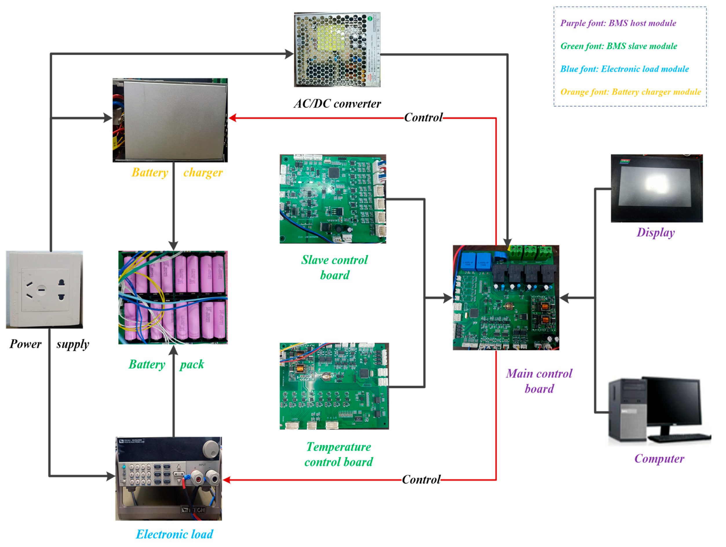
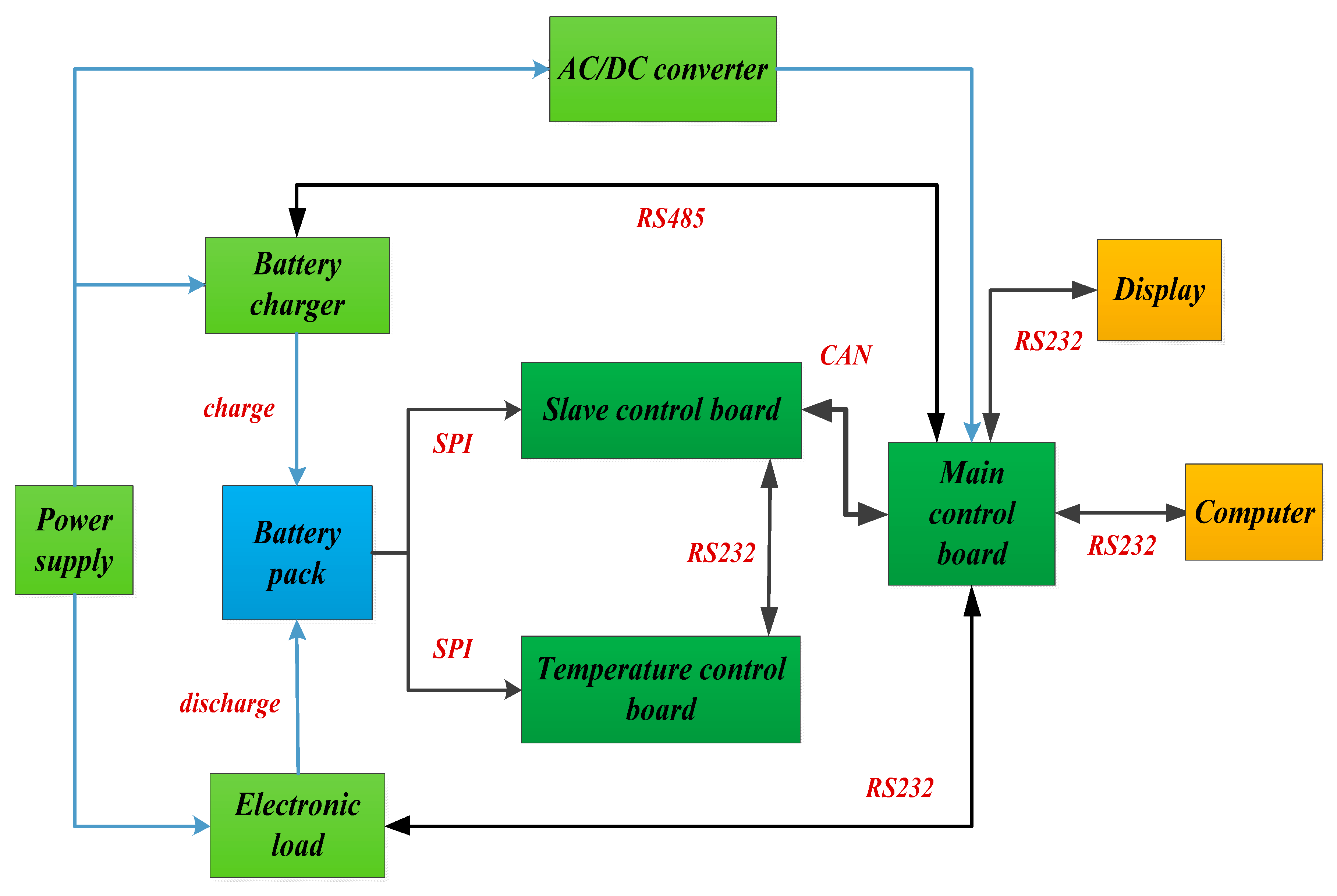
The hardware components of the lithium-ion batteries SOC estimation algorithm verification platform mainly have four modules, including the BMS host module (master control board, display screen, and upper computer), BMS slave module (slave control board, temperature control board, and battery pack), battery charger and programmable electronic load. The hardware structure design is shown in Figure 2. The verification platform can set different charge and discharge modes through the upper computer or display screen, and send control signals to the battery charger and electronic load from the main control board to implement the predetermined charge and discharge mode for the battery pack. The temperature control board and slave control board are responsible for collecting the voltage, current, temperature, and other information of the battery pack during the charge and discharge process and transmitting the collected data to the main control board, including the relevant state parameters of the battery pack and each battery cell. The main control board maintains communication with the host computer, transmits the collected battery data in real-time, stores the data in the corresponding software, and calculates the SOC reference value and the estimation value of the new estimation algorithm through the collected data, so as to verify and evaluate the SOC estimation method of the battery cell and pack.

3.1. BMS Host Module

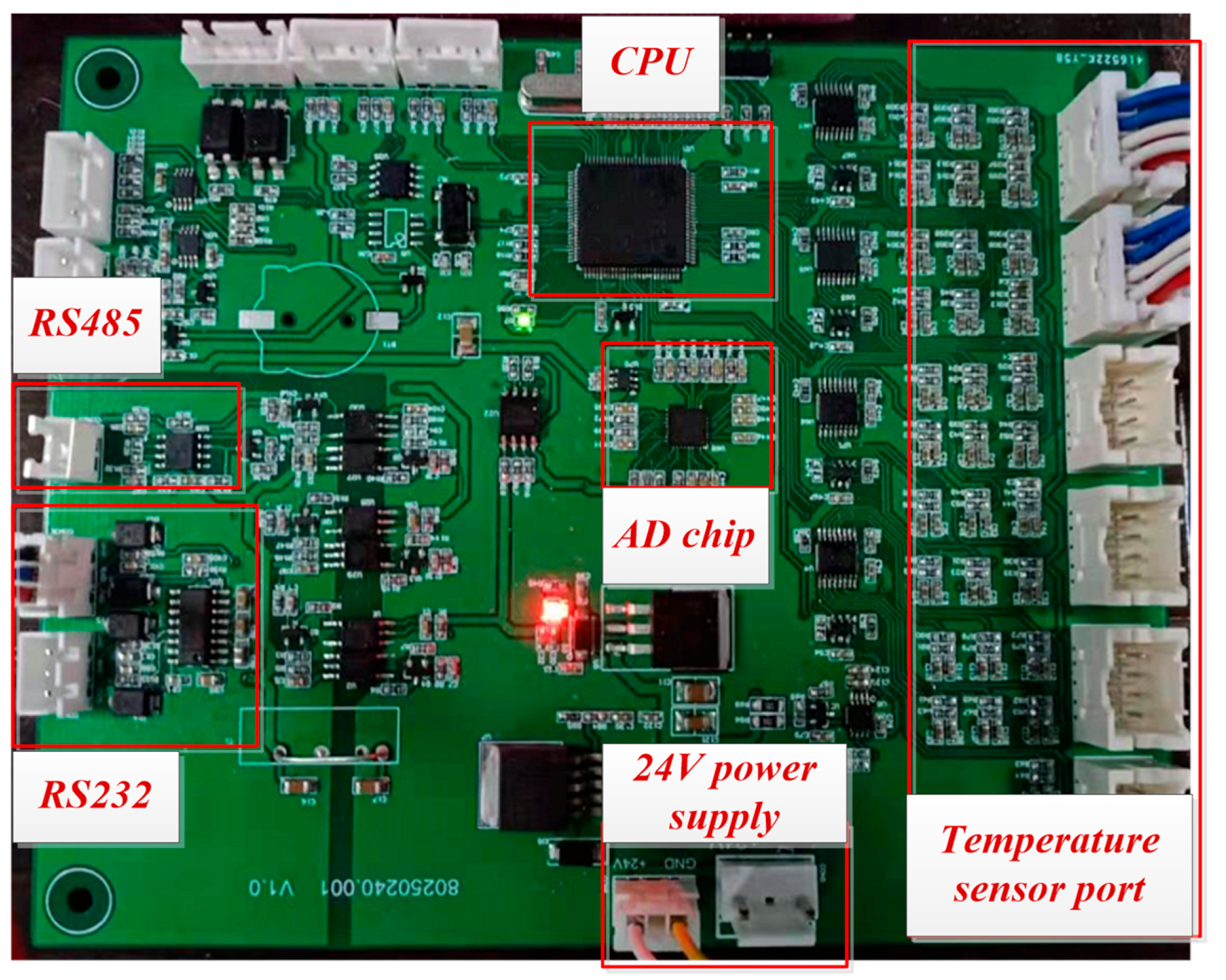
The BMS host module includes the main control board, upper computer, and display screen. The upper computer and display screen are mainly used for human-computer interaction and battery data information display. The main control board is responsible for coordinating the work of other modules, mainly realizing the following functions, including battery charging module management (RS485), battery discharge module management (RS232), upper computer communication (RS232), slave control board communication (CAN bus), display screen communication (RS232), passive equalization management and data storage management. It is also responsible for receiving current, voltage, and temperature data from the slave control board and temperature control board, calculating the battery SOC reference value and predicting the value of the new SOC estimation algorithm, and making comprehensive verification and evaluation of the new SOC estimation algorithm. The hardware structure of the main control board is shown in Figure 3.

3.2. BMS Slave Module

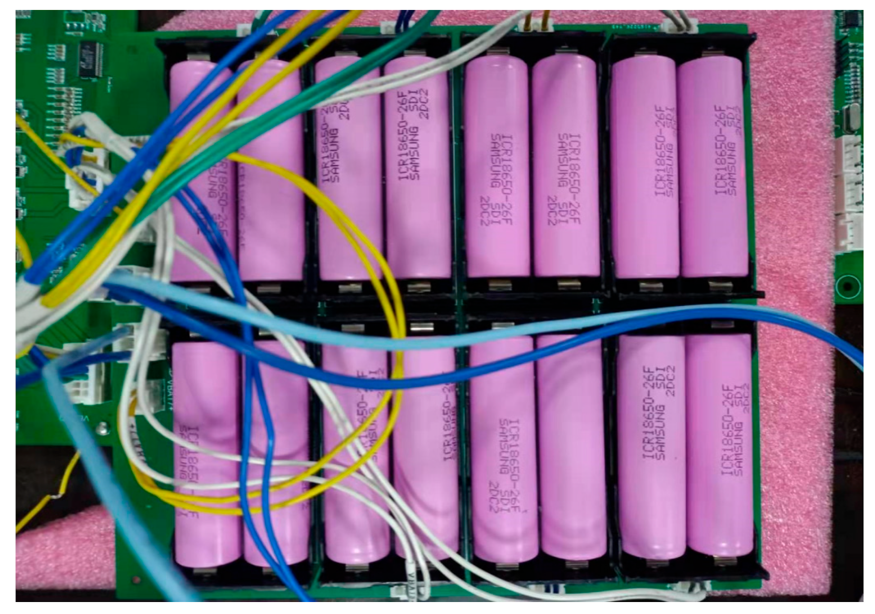
The BMS slave module includes a battery pack, slave control board, and temperature control board, and their hardware structures are shown in Figure 4, Figure 5 and Figure 6, respectively. The battery pack adopts the form of 2 parallel and 8 series (parallel first and then series), which is composed of 16 battery cells in total and can be reorganized according to the specific test needs. Passive equalization (bypass resistance energy consumption) is adopted to ensure a good consistency between battery cells. The slave control board is mainly responsible for collecting the current and voltage signals of the batteries, supporting multi-channel voltage monitoring, communicating with the main control board through the CAN bus, implementing the passive equalization strategy, and communicating with the temperature control board through the RS232 serial port to receive the temperature data of the batteries. The temperature control board is mainly responsible for collecting the temperature signal of each battery cell and supporting multi-channel temperature monitoring. At the same time, the information obtained from the temperature control board and the slave control board will be transmitted to the main control board to realize the safety management of the battery pack and the verification and evaluation of the SOC estimation algorithm. The functional parameters of the BMS slave monitoring circuit are shown in Table 1.

3.3. Battery Charger Module

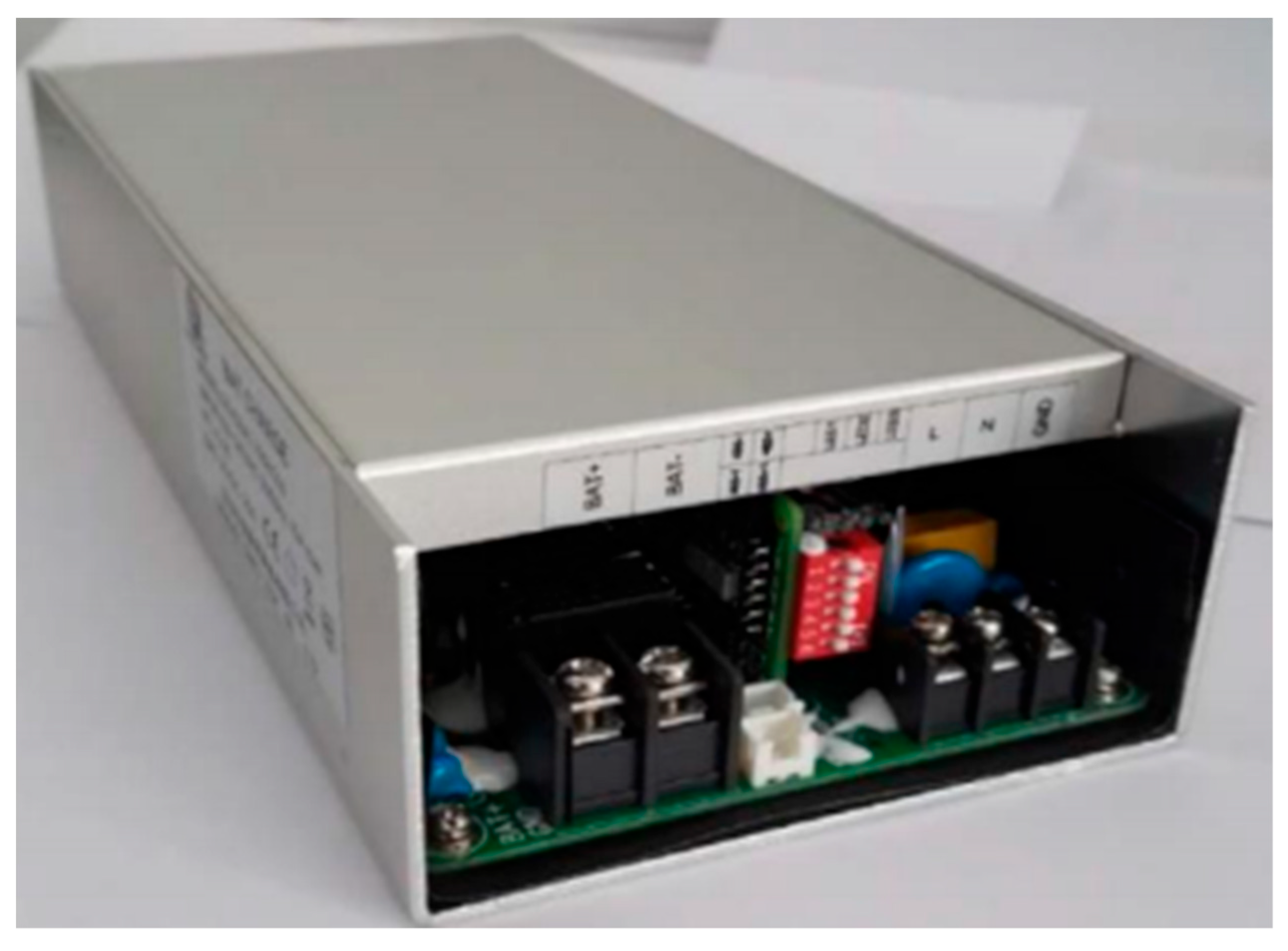
The battery charger used in the verification platform is a special charger for lithium-ion batteries. Its model is GSADBAT-750W75S, which is a high-power supply with alternating current/direct current (AC/DC) output. The built-in microprocessor intelligently manages to charge and has an RS485 communication function. The output voltage and current of the charger can be adjusted through software to realize three charging modes, including multi-stage constant current charging, automatic voltage regulation charging, and constant current constant voltage charging. The schematic diagram of the battery charger is shown in Figure 7.

3.4. Programmable Electronic Load Module

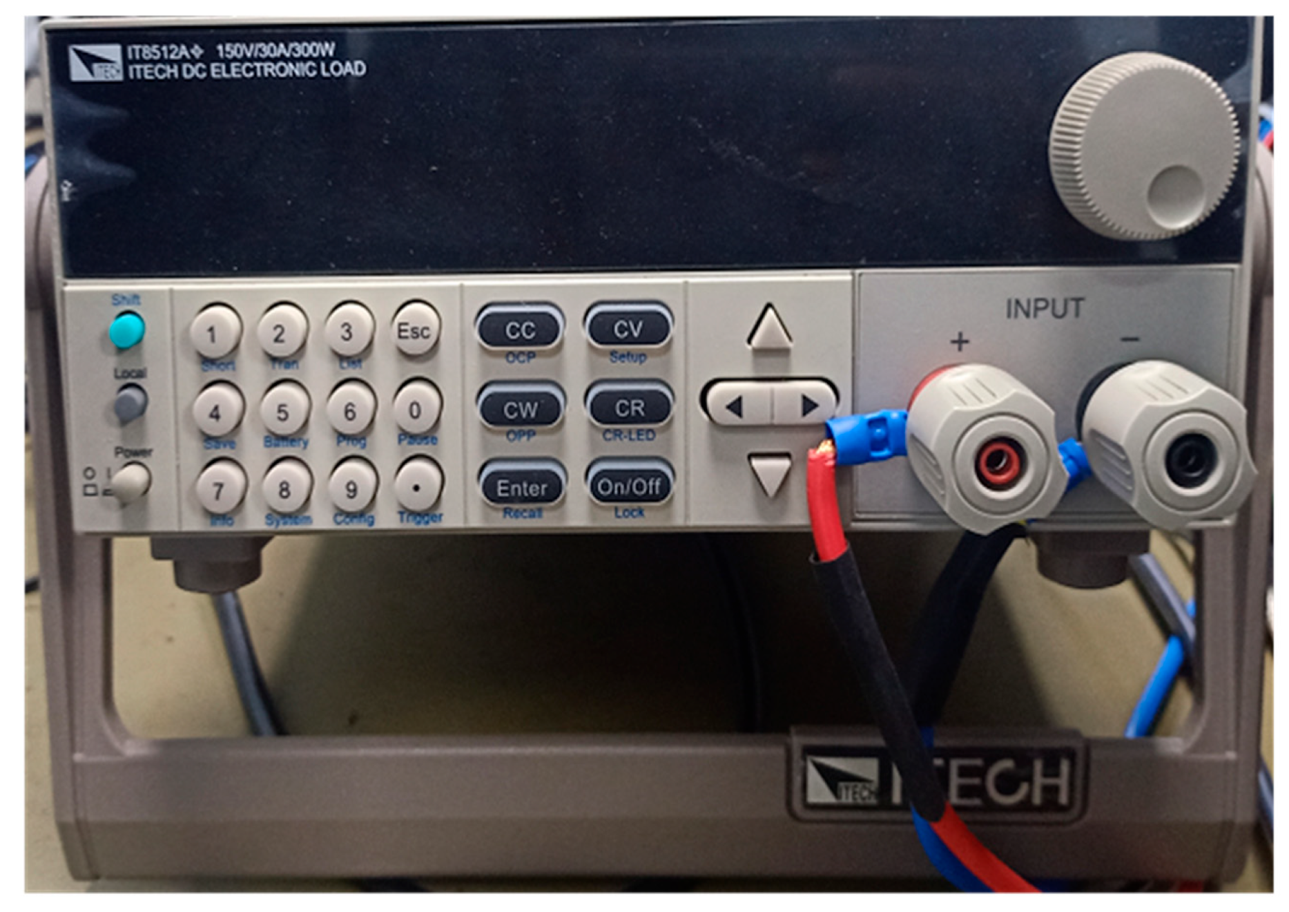
The model of the programmable electronic load is IT8512A+, which has the characteristics of high precision and high resolution. At the same time, it has a variety of test functions, such as automatic tests and dynamic tests. The schematic diagram of it is shown in Figure 8. The discharge load is a programmable direct load, which can set the discharge current, power, and resistance of the battery according to the needs of the battery pack discharge test and can realize four discharge modes, including constant current discharge, constant voltage discharge, constant power discharge, and constant resistance discharge. Moreover, the current data of some typical driving cycle conditions can also be added to the software in advance, and the required charge and discharge mode can be directly selected during the test. The charge and discharge modes (driving cycle conditions) that can be selected include the New European Driving Cycle (NEDC), the Federal Urban Driving Schedule (FUDS), the Urban Dynamometer Driving Schedule (UDDS), and the Dynamic Stress Test (DST).

4. Software System Design

4.1. Communication Framework between Modules

The energy information flow between the modules of the lithium-ion batteries SOC estimation algorithm verification platform is shown in Figure 9. The black arrow shows the process of information flow, and the blue arrow shows the process of energy flow. The information interaction between modules needs to be realized by a communication protocol, and the selection of protocol needs to be determined according to the specific equipment and chip used. The communication protocols used by the verification platform have four categories, including the RS232 serial port protocol, RS485 bus protocol, CAN bus, and serial peripheral interface (SPI) protocol. Programmable electronic load equipment provides users with two communication interfaces, including RS232 and RS485. Based on the SPI protocol, the AD conversion chip is used to measure the current, voltage, and temperature of the battery from the slave control board and temperature control board, and the battery charger equipment only provides users with an RS485 interface. The CAN bus protocol is selected for the communication between the master control board and the slave control board because the CAN bus is a commonly used protocol between various parts of the car—only two differential twisted pair wires can be used to mount many slave devices. It is also easy to expand the slave control board when the number of battery cells increases. The main control board belongs to a slave in the whole automotive electronic system and is also connected to the automotive electronic central controller through the CAN bus. The communication protocols adopted by each module on the verification platform are summarized in Table 2.

4.2. Reference Standard of SOC and Evaluation Indexes of Method

The software system of the verification platform also needs to formulate the reference standard of SOC estimation results, the comprehensive performance evaluation indexes of the SOC estimation method, and the specific evaluation process. For the comprehensive verification and evaluation of the advantages and disadvantages of the new SOC estimation method, the memory occupation rate, estimation time, and estimation accuracy (average absolute error, root mean square error, and maximum absolute error) of the estimation algorithm are mainly selected as the evaluation indexes. The specific evaluation process is shown in Figure 10.

4.2.1. Reference Standard of Battery Cell SOC

For the reference standard of battery cell SOC estimation results, the SOC reference value is obtained by the combination of the open-circuit voltage method and ampere-hour integration method [18], that is, the initial value of the SOC for charge and discharge is obtained by checking the table of the corresponding relationship between OCV and SOC, and then the SOC value at t time is calculated by the formula (1). Where SOC0 is the initial state of charge value of the battery cell during charge and discharge, SOCt is the state of charge value at t time, i and Q represent the charge and discharge current and the rated capacity of the battery cell, respectively.
S O C t = S O C 0 1 Q 0 t i ( t ) d t

4.2.2. Reference Standard of Battery Pack SOC

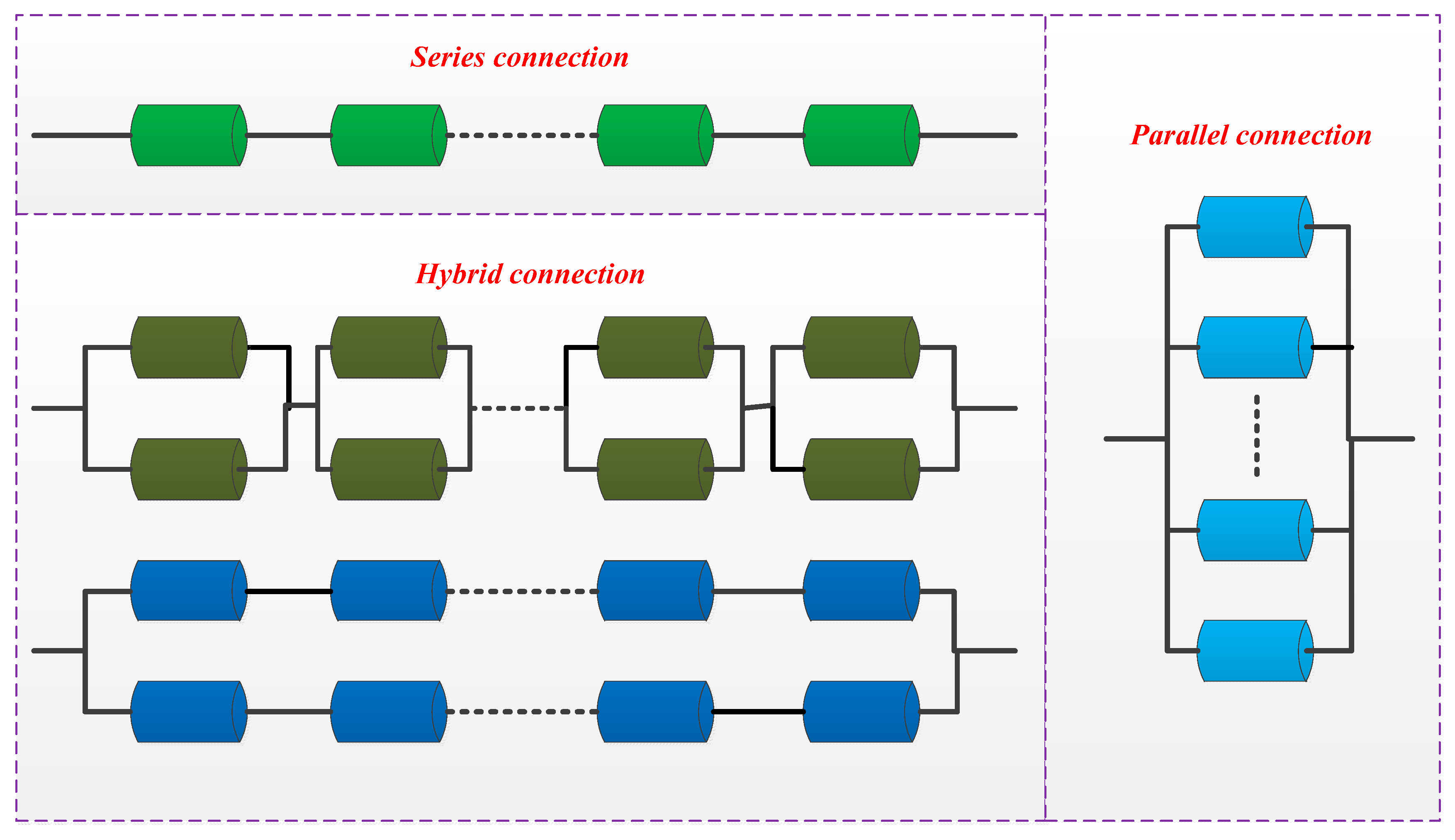
The battery pack of EVs is usually composed of hundreds of battery cells. Due to the inconsistency between cells, the definition of battery pack SOC is much more complex than cells [14,19,20]. Just like the battery cell SOC, the battery pack SOC is also defined as the ratio of remaining available capacity to rated capacity under the same conditions. The difference is the battery pack SOC needs to be calculated according to the weighted average of all battery cells’ SOC and their rated capacity. The calculation of its remaining available capacity and rated capacity can be divided into series, parallel, and hybrid structures for discussion and analysis. Finally, the battery pack SOC reference standard of the verification platform is calculated by the definition of the battery pack SOC. Different battery pack structures are shown in Figure 11.
(1)
Series connection battery pack SOC
For the battery pack composed of n battery cells in series, assuming that the rated capacity and SOC value of each cell is Qi and SOCi, respectively, it can be obtained that the rechargeable capacity and discharge capacity of each battery cell are Qj × (1 − SOCj) and Qi × SOCi. In order to ensure that the battery pack does not overcharge or discharge, the current rated capacity Qpack and SOC of the series battery pack can be calculated by the formulas (2) and (3).
Q p a c k = min 1 i n Q i × S O C i + min 1 j n Q j × 1 S O C j
S O C p a c k = min 1 i n Q i × S O C i min 1 i n Q i × S O C i + min 1 j n Q j × 1 S O C j
(2)
Parallel connection battery pack SOC
Assume that the rated capacity and SOC value of each cell of the battery pack composed of n battery cells in parallel are Qi and SOCi, respectively. Because all battery cells in the parallel battery pack can achieve full charge and discharge, the rated capacity and available capacity of the parallel battery pack are the sum of the rated capacity and available capacity of all cells, respectively. Therefore, the parallel battery pack SOC can be calculated by the formula (4).
S O C p a c k = i = 1 n Q i × S O C i i = 1 n Q i
(3)
Hybrid connection battery pack SOC
The SOC value calculation formulas of two typical hybrid battery packs are analyzed as follows. On the one hand, as for the m parallel n series (parallel first and then series) hybrid battery pack, assuming that the SOC value and rated capacity of each series unit are SOCi and Qi, and the SOC value and rated capacity of each battery cell are SOCij and Qij, respectively, where i ∈ [1, 2, …, n], j ∈ [1, 2, …, m]. Based on the analysis of the parallel connection battery pack SOC above, the SOCi and Qi can be calculated using the following formulas (5) and (6).
Q i = j = 1 m Q i j
S O C i = j = 1 m Q i j × S O C i j j = 1 m Q i j
Based on the analysis of the series connection battery pack SOC above, the rated capacity Qpack and SOC value SOCpack of m parallel n series hybrid battery pack are calculated using the formulas (7) and (8).
Q p a c k = min 1 i n Q i × S O C i + min 1 k n Q k × 1 S O C k
S O C p a c k = min 1 i n Q i × S O C i min 1 i n Q i × S O C i + min 1 k n Q k × 1 S O C k
On the other hand, as for the m series n parallel (series first and then parallel) hybrid battery pack, assuming that the SOC value and rated capacity of each parallel unit are SOCi and Qi, and the SOC value and rated capacity of each battery cell are SOCij and Qij, respectively, where i ∈ [1, 2, …, n], j ∈ [1, 2, …, m]. Based on the analysis of the series connection battery pack SOC above, the SOCi and Qi can be calculated using the following formulas (9) and (10).
Q i = min 1 j m Q i j × S O C i j + min 1 k m Q i k × 1 S O C i k
S O C i = min 1 j m Q i j × S O C i j min 1 j m Q i j × S O C i j + min 1 k m Q i k × 1 S O C i k
Based on the analysis of the parallel connection battery pack SOC above, the rated capacity Qpack and SOC value SOCpack of the m series n parallel hybrid battery pack are calculated using the formulas (11) and (12).
Q p a c k = i = 1 m Q i
S O C p a c k = i = 1 n Q i × S O C i i = 1 n Q i
For the hybrid battery pack with more complex structures, the method to calculate the battery pack SOC reference standard is to decompose the hybrid battery pack into several series units and parallel units firstly, calculate the rated capacity Qi and state of charge SOCi of the series units and parallel units using the formulas (2)–(4), and then calculate the battery pack SOC reference value according to the structural relationship between all series units and parallel units [21].

4.3. Function and Implementation of Upper Computer

This paper designs the upper computer of the SOC estimation algorithm verification platform based on MATLAB 2020a, and the main functions of the upper computer include the following three aspects. (1) Information human-computer interaction: in the process of charging and discharging the battery pack, the upper computer displays the status information of the battery pack and the battery cell in real-time, such as current, cell voltage, the total voltage of the battery pack, cell SOC, battery pack SOC, estimation error and so on. (2) Providing data interface: the battery pack current, voltage, temperature, and other information received by the upper computer from the lower computer can be used as the data input of the new SOC estimation method, and different new SOC estimation methods can be added for verification and evaluation. (3) Controlling the behavior of the lower computer: the upper computer can control the charge and discharge module to implement a specific charge and discharge mode for the battery pack, evaluate the comprehensive performance of the new SOC estimation method under different driving cycle conditions and improve the reliability of the verification and evaluation results. The upper computer can also set battery alarm parameters to protect the safety of the battery in the process of charging and discharging.
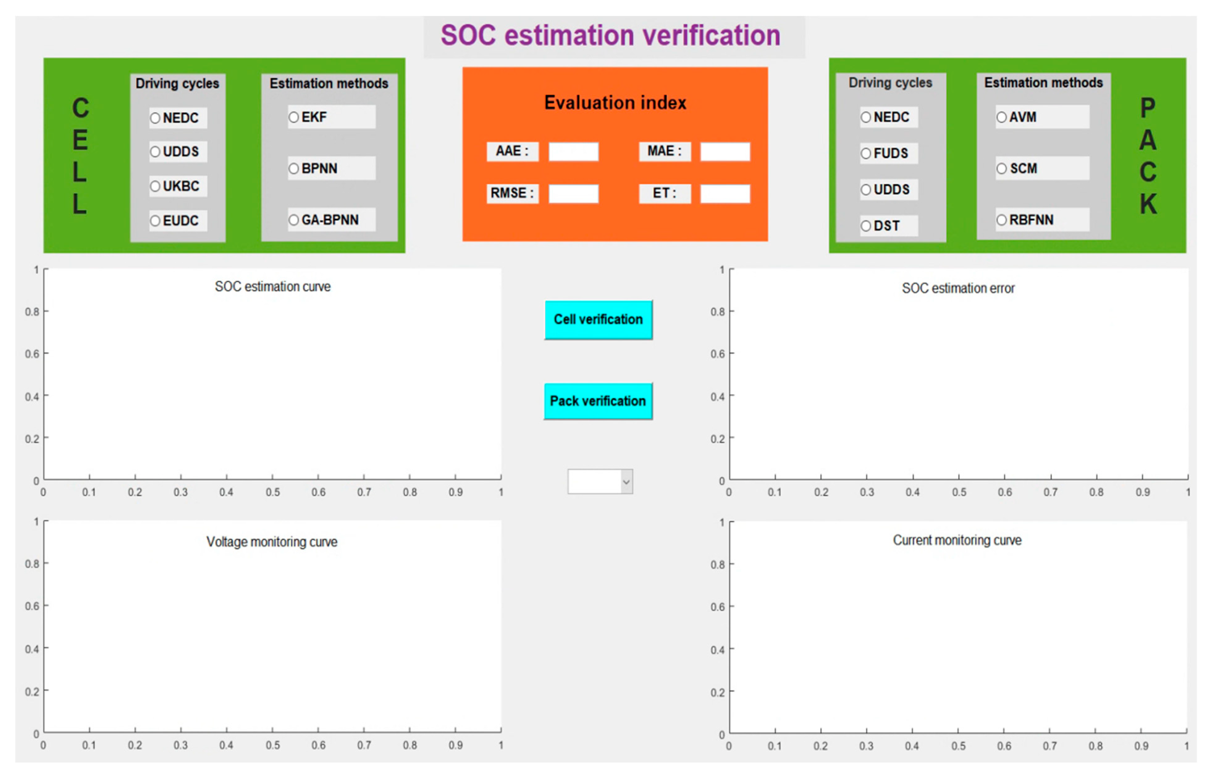
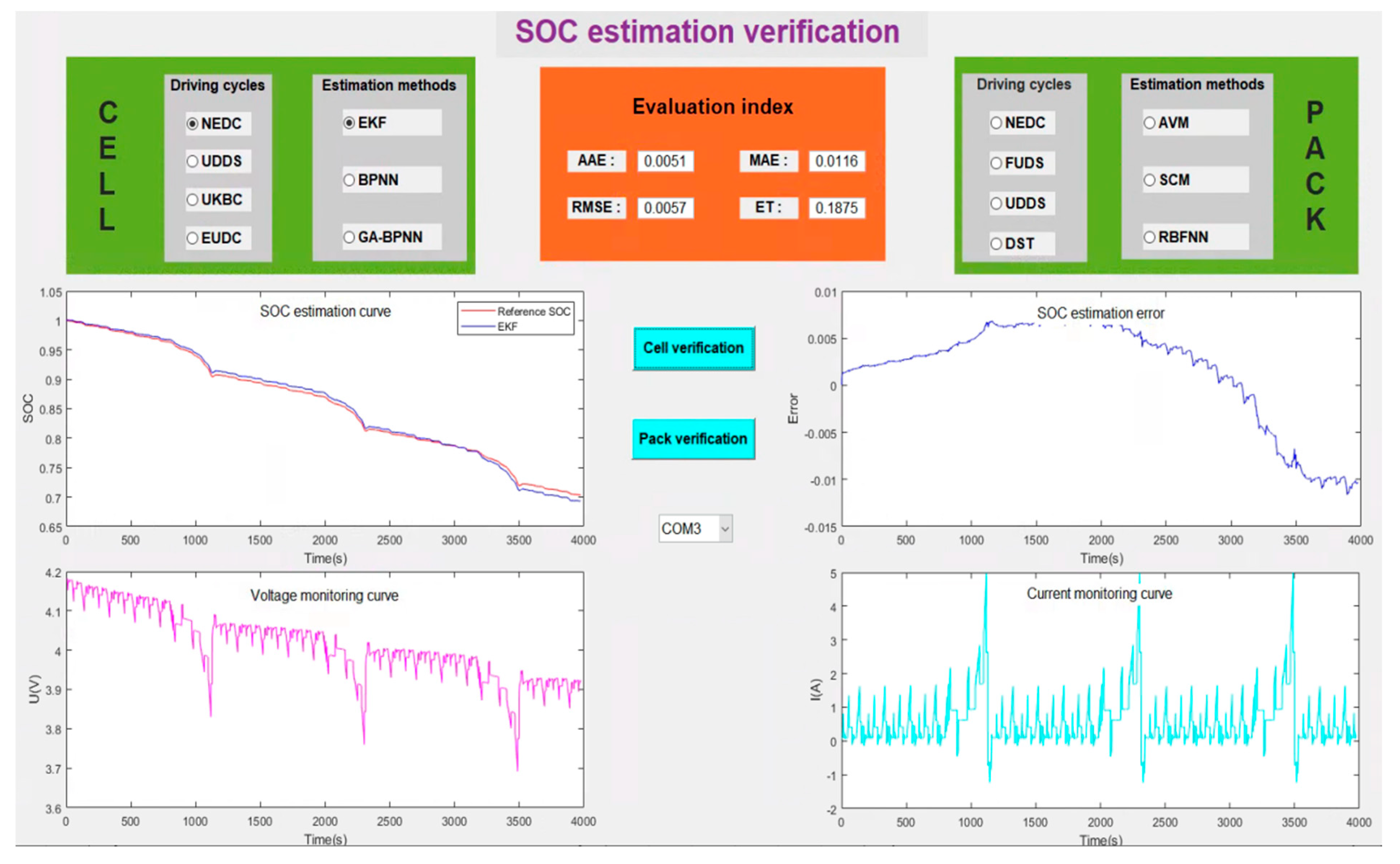
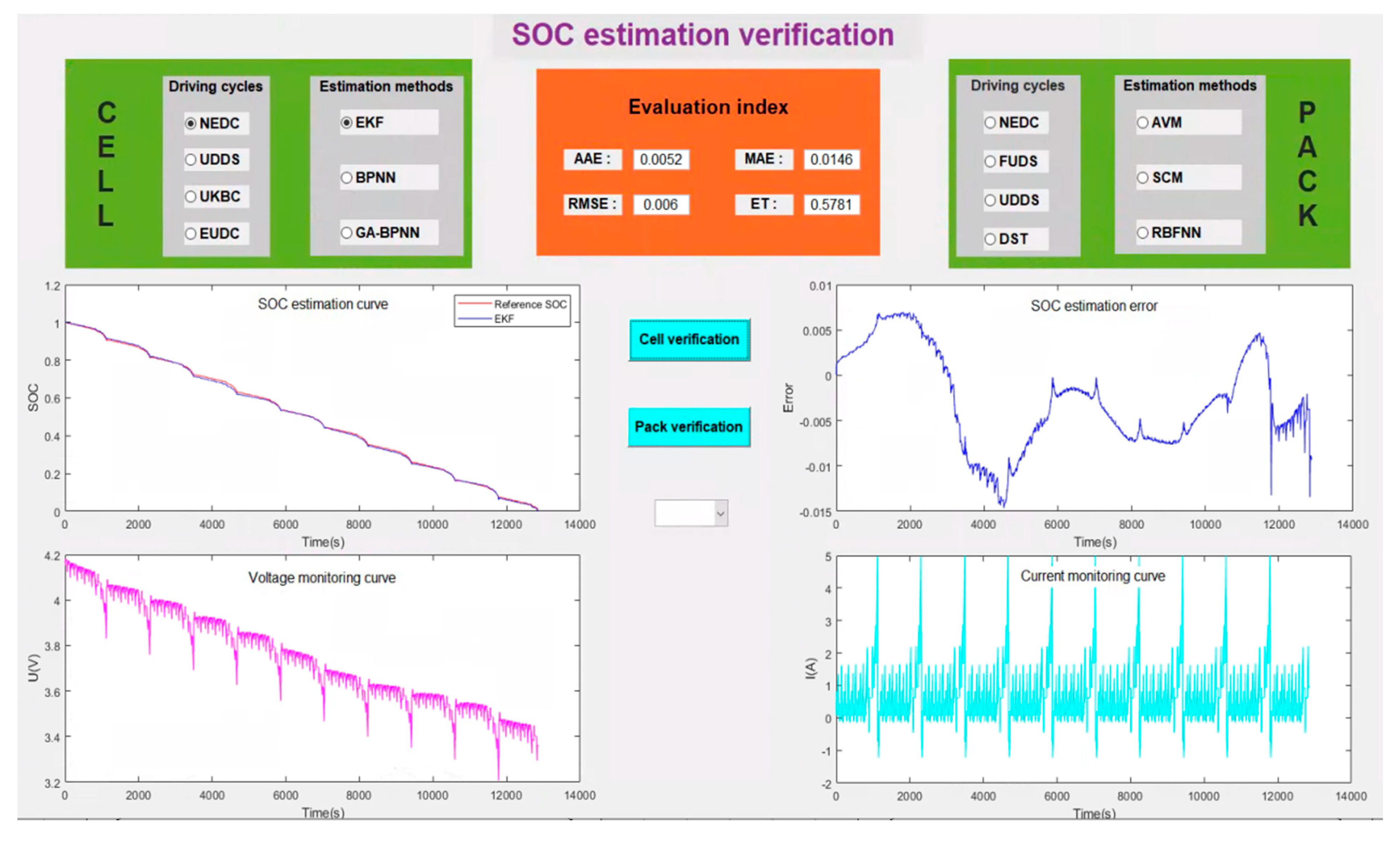
The initial interface of the upper computer software written based on the MATLAB 2020a GUIDE module is shown in Figure 12. It can select the battery cell or battery pack for SOC estimation verification and evaluation, respectively. The evaluation indexes of the estimation method include average absolute error (AAE), maximum absolute error (MAE), root mean square error (RMSE), and estimation time (ET) [7,22]. As for battery cells, there are four driving cycle conditions, including NEDC, UDDS, the United Kingdom Bus Cycle (UKBC), and the Extra Urban Driving Cycle (EUDC), and three estimation methods, including the Extended Kalman filter (EKF) [23], the back-propagation neural network (BPNN) and the genetic algorithm optimized back-propagation neural network (GA-BPNN) can be selected [24,25]. New estimation methods of the battery cell SOC can be added to the source code for verification. As for the battery pack, there are also four driving cycle conditions, including NEDC, FUDS, UDDS, and DST, and three estimation methods, including the average value method (AVM) [26], special cell method (SCM) and the radial basis function neural network method (RBFNN) [27,28]. New estimation methods of the battery pack SOC can also be added to the source code for verification. The images displayed in real-time during the process of verification include the SOC estimation curve (reference value and estimated value), SOC estimation error curve, voltage real-time monitoring curve, and current real-time monitoring curve.
Considering the time cost of the SOC estimation method verification process, this paper designs two schemes, including real-time SOC estimation verification and offline SOC estimation verification. As for the real-time SOC estimation verification, the communication between the upper computer and the main control board is established through the RS232 protocol. The upper computer can receive the signals of the battery voltage, current, and temperature uploaded by the main control board in real-time, and estimate the SOC of the battery cell and battery pack. As for the offline SOC estimation verification, the charge and discharge current, voltage, temperature, and other data of various test conditions are saved in the upper computer in advance. After the test condition is selected, the corresponding battery charge and discharge data are directly read for the SOC estimation and verification. The verification efficiency of the offline SOC estimation verification is higher than the real-time SOC estimation verification. The process of real-time SOC estimation verification and offline SOC estimation verification are shown in Figure 13 and Figure 14, respectively. The figures show the battery cell SOC estimation results and evaluation indexes of the EKF method under NEDC.

5. Results Analysis

At present, scholars in the field of batteries have proposed a variety of seemingly high-precision, high-performance battery SOC estimation algorithms, but the so-called high-precision is based on what kind of reference standards? High performance is based on what kind of evaluation indexes? Verification is based on what kind of charge and discharge test conditions? These do not have a unified standard. Therefore, this paper establishes a SOC estimation algorithm verification platform for the efficient and reliable verification of the new SOC estimation algorithms; the hardware structure and software system of the verification platform is introduced in detail. The proposal in this paper does not rely on specific tools to achieve, and it can be replicated in any lab after appropriate modifications, however, the following key issues need to be paid attention to when replicating.
As for the hardware structure, the data acquisition device should be able to achieve high-precision measurement of the current, voltage, temperature, and other data of the battery cell and pack, corresponding to the slave control board and temperature control board in the paper. The battery charge and discharge devices must be able to implement complex conditions of charge and discharge tests, such as NEDC, UDDS, and FUDS, so as to fully simulate the real state of the battery system in the operation of EVs and enhance the reliability of algorithm verification. The battery charge and discharge devices correspond to the battery charger and programmable electronic load in the paper. The main control device can receive the current, voltage, and temperature data of the battery to calculate the SOC reference value and the estimated value and make a comprehensive verification evaluation of the algorithm according to the evaluation index. The main control device corresponds to the main control board in the paper. Moreover, the devices can communicate with each other; the data measured by the lower computer can be transmitted to the upper computer in real-time, and the upper computer can control the lower computer to ensure that the battery can implement a specific charge and discharge mode and the safety of the battery during the test.
The software system needs to formulate the reference standards of the SOC estimation results, the comprehensive performance evaluation indexes of the SOC estimation method, and the specific evaluation process. Firstly, the battery cell SOC reference value is calculated by the combination of the open-circuit voltage method and ampere-hour integration method, which needs to test the battery in advance to obtain the corresponding relationship between OCV and SOC, so as to obtain the accurate initial value of the SOC, and then integrate the discharge current to obtain the SOC reference value at t time; therefore, the measured current must have high accuracy. The battery pack SOC reference value shall be obtained according to the SOC calculation formula of the battery pack with different structures in Section 4.2.2. Further, the memory occupation rate, estimation time, and estimation accuracy (AAE, RMSE, and MAE) of the estimation algorithm are mainly selected as the evaluation indexes of the SOC estimation method. Finally, the specific verification and evaluation process of the algorithm performance needs to refer to Figure 10 in this paper.

6. Conclusions

In this paper, a lithium-ion battery’s SOC estimation algorithm verification platform is established for the comprehensive performance evaluation and verification of the new SOC estimation algorithm. Firstly, the design idea of the verification platform (research and development purpose, functional requirements, and the overall design scheme) is introduced in detail. Secondly, the hardware structure of the verification platform is established, which includes the BMS host module, the BMS slave module, the battery charger module, and the programmable electronic load module; each module can realize specific functions, such as data acquisition, information interaction, and control management. Finally, the software system, including the communication architecture, SOC reference standard and evaluation indexes of the algorithm, and the upper computer function and implementation are designed, and each module can realize efficient communication and comprehensively verify and evaluate the new SOC estimation algorithm. Both the battery cell and battery pack can be chosen for adding new methods and discharge conditions for verification, and there are two schemes, including the real-time SOC estimation verification and the offline SOC estimation verification that can be selected, which improve the reliability and efficiency of verification. Moreover, the verification platform has the functions of battery SOC estimation, charging and discharging, information acquisition, equalization control, etc., so the verification platform cannot only be used to research different SOC estimation algorithms but can also be extended to the research of battery charging strategy, equalization strategy, and other BMS functionalities.
Future work will focus on the verification and evaluation of the intelligent equalization strategy, charging strategy, and other BMS functionalities to ensure that the work of the battery pack is safe and efficient. Moreover, a new trend in the battery state estimation community is to use an electrochemical model for battery SOC estimation [29,30]. This requires the measurement of electrode potential using a reference electrode for verification; the verification platform established in this paper cannot be used to verify these methods, which is another direction that also needs to be explored and improved on in our future work.

Author Contributions

B.X.: supervision, resources, project administration, methodology, funding acquisition; G.Z.: conceptualization, methodology, validation, writing—original draft, software, visualization, writing—review and editing; H.C.: methodology, writing—review and editing; Y.L.: visualization, writing—review and editing; Z.Y.: conceptualization, writing—review and editing; Y.C.: validation, writing—original draft. All authors have read and agreed to the published version of the manuscript.

Funding

This research was funded by the National Natural Science Foundation of China (Grant No. 51877120).

Institutional Review Board Statement

Not applicable.

Informed Consent Statement

Not applicable.

Data Availability Statement

Not applicable.

Acknowledgments

This work was funded by the research on the SOC/SOH Joint Estimation Technology of Electric Vehicle Battery System State based on the Online Parameter Identification Project (2019), and the National Natural Science Foundation of China (Grant No. 51877120).

Conflicts of Interest

The authors declare no conflict of interest.

Nomenclature

AAEAverage absolute error
AC/DCAlternating current/Direct current
ADAnalog to Digital
AVMAverage value method
BMSBattery management system
BPNNBack-propagation neural network
CANController area network
CPUCentral processing unit
DSTDynamic Stress Test
EKFExtend Kalman filter
ETEstimation time
EUDCExtra Urban Driving Cycle
EVsElectric vehicles
FSRFull scale range
FUDSFederal Urban Driving Schedule
GA-BPNNGenetic algorithm optimized back-propagation neural network
HILHardware-in-the-loop
MAEMaximum absolute error
NEDCNew European Driving Cycle
OCVOpen circuit voltage
RMSERoot mean square error
RBFNNRadial basis function neural network
RSRecommended Standard
SOCState of charge
SCMSpecial cell method
SPISerial Peripheral Interface
UDDSUrban Dynamometer Driving Schedule
UKBCUnited Kingdom Bus Cycle

References

  1. Jinhao, M.; Guangzhao, L.; Mattia, R.; Maciej, S.; Daniel-Ioan, S.; Remus, T. Overview of lithium-ion batteries modeling methods for state-of-charge estimation in electrical vehicles. Appl. Sci. 2018, 8, 659. [Google Scholar]
  2. Zhang, N.; Zhou, Y.; Tian, Q.; Liao, X.; Zhang, F. A Novel Method for Estimating State-of-Charge in Power Batteries for Electric Vehicles. Int. J. Precis. Eng. Manuf. 2019, 20, 845–852. [Google Scholar] [CrossRef]
  3. Xu, G.; Du, X.; Li, Z.; Zhang, X.; Zheng, M.; Miao, Y.; Gao, Y.; Liu, Q. Reliability design of battery management system for power battery. Microelectron. Reliab. 2018, 88–90, 1286–1292. [Google Scholar] [CrossRef]
  4. Li, L.; Li, Z.; Zhao, J.; Guo, W. Lithium-ion batteries Management System for Electric Vehicles. Int. J. Perform. Eng. 2018, 14, 3184–3194. [Google Scholar] [CrossRef] [Green Version]
  5. Salehen, P.; Su’Ait, M.; Razali, H.; Sopian, K. Development of battery management systems (BMS) for electric vehicles (EVs) in Malaysia. MATEC Web Conf. 2016, 90, 1001. [Google Scholar] [CrossRef] [Green Version]
  6. Chen, Z.; Li, X.; Shen, J.; Yan, W.; Xiao, R. A Novel State of Charge Estimation Algorithm for Lithium-Ion Battery Packs of Electric Vehicles. Energies 2016, 9, 710. [Google Scholar] [CrossRef]
  7. Zhang, Y.; Xiong, R.; He, H.; Shen, W. Lithium-Ion Battery Pack State of Charge and State of Energy Estimation Algorithms Using a Hardware-in-the-Loop Validation. IEEE Trans. Power Electron. 2017, 32, 4421–4431. [Google Scholar] [CrossRef]
  8. Sheng, J. Test Verification System of New Energy Automobile Power Battery SOC Estimation Tactics. China Patent CN201620496696.6, 13 February 2016. [Google Scholar]
  9. Guo, B.; Zhang, P.; Wang, W. Research on SOC estimation of LiFePO4battery based on OCV-SOC curve cluster. Chin. J. Power Sources 2019, 43, 1125–1128. [Google Scholar]
  10. Guo, L.; Li, J.; Fu, Z. Lithium-Ion Battery SOC Estimation and Hardware-in-the-Loop Simulation Based on EKF. Energy Procedia 2019, 158, 2599–2604. [Google Scholar] [CrossRef]
  11. He, Y.; Liu, W.; Koch, B.J. Battery algorithm verification and development using hardware-in-the-loop testing. J. Power Source 2010, 195, 2969–2974. [Google Scholar] [CrossRef]
  12. Zhang, W.; Sun, X.; Lei, W. Battery Pack State of Charge Estimation and Hardware in Loop System Design Verification. In Proceedings of the 2017 9th International Conference on Intelligent Human-Machine Systems and Cybernetics (IHMSC), Hangzhou, China, 26–27 August 2017. [Google Scholar]
  13. Xia, B.; Chen, G.; Zhou, J.; Yang, Y.; Huang, R.; Wang, W.; Lai, Y.; Wang, M.; Wang, H. Online Parameter Identification and Joint Estimation of the State of Charge and the State of Health of Lithium-Ion Batteries Considering the Degree of Polarization. Energies 2019, 12, 2939. [Google Scholar] [CrossRef] [Green Version]
  14. Xie, S.; Xiong, R.; Zhang, Y.; He, H. The Estimation of State of Charge for Power Battery Packs used in Hybrid Electric Vehicle. Energy Procedia 2017, 105, 2678–2683. [Google Scholar] [CrossRef]
  15. Xia, B.; Guo, S.; Wang, W.; Lai, Y.; Wang, H.; Wang, M.; Zheng, W. A State of Charge Estimation Method Based on Adaptive Extended Kalman-Particle Filtering for Lithium-ion Batteries. Energies 2018, 11, 2755. [Google Scholar] [CrossRef] [Green Version]
  16. Singh, K.V.; Bansal, H.O.; Singh, D. Hardware-in-the-loop Implementation of ANFIS based Adaptive SoC Estimation of Lithium-ion Battery for Hybrid Vehicle Applications. J. Energy Storage 2020, 27, 101124. [Google Scholar] [CrossRef]
  17. Cui, D.; Xia, B.; Zhang, R.; Sun, Z.; Lao, Z.; Wang, W.; Sun, W.; Lai, Y.; Wang, M. A Novel Intelligent Method for the State of Charge Estimation of Lithium-Ion Batteries Using a Discrete Wavelet Transform-Based Wavelet Neural Network. Energies 2018, 11, 995. [Google Scholar] [CrossRef] [Green Version]
  18. Gismero, A.; Schaltz, E.; Stroe, D.-I. Recursive State of Charge and State of Health Estimation Method for Lithium-Ion Batteries Based on Coulomb Counting and Open Circuit Voltage. Energies 2020, 13, 1811. [Google Scholar] [CrossRef] [Green Version]
  19. Zhang, G.; Xia, B.; Wang, J. Intelligent state of charge estimation of lithium-ion batteries based on L-M optimized back-propagation neural network. J. Energy Storage 2021, 44, 103442. [Google Scholar] [CrossRef]
  20. Xiong, R.; Sun, F.; Gong, X.; He, H. Adaptive state of charge estimator for lithium-ion cells series battery pack in electric vehicles. J. Power Source 2013, 242, 699–713. [Google Scholar] [CrossRef]
  21. Sun, F.; Xiong, R.; He, H. A systematic state-of-charge estimation framework for multi-cell battery pack in electric vehicles using bias correction technique. Appl. Energy 2016, 162, 1399–1409. [Google Scholar] [CrossRef]
  22. Xiong, R.; He, H.; Sun, F.; Zhao, K. Online Estimation of Peak Power Capability of Li-Ion Batteries in Electric Vehicles by a Hardware-in-Loop Approach. Energies 2012, 5, 1455–1469. [Google Scholar] [CrossRef]
  23. Fan, B.; Luan, X.; Zhang, R.; Niu, T.; Xie, Y. Research on SOC Estimation Algorithm for Lithium Battery Based on EKF Algorithm and Ampere-hour Integration Method. In Proceedings of the 2017 2nd International Conference on Electrical, Control and Automation Engineering (ECAE 2017), Xiamen, China, 24–25 December 2017. [Google Scholar] [CrossRef] [Green Version]
  24. Ren, G.; Lin, Y.; Sun, Z.; Shao, Y. SOC Estimation of Mine Power Supply Based on Improved BP Neural Network Algorithm. IOP Conf. Ser. Earth Environ. Sci. 2020, 526, 012112. [Google Scholar] [CrossRef]
  25. Wang, L.; Zhou, H.; Yang, J.; Xiong, Y.; She, J.; Chen, W. A decision support system for tobacco cultivation measures based on BPNN and GA. Comput. Electron. Agric. 2021, 181, 105928. [Google Scholar] [CrossRef]
  26. Zheng, Y.; Ouyang, M.; Lu, L.; Li, J.; Han, X.; Xu, L.; Ma, H.; Dollmeyer, T.A.; Freyermuth, V. Cell state-of-charge inconsistency estimation for LiFePO4 battery pack in hybrid electric vehicles using mean-difference model. Appl. Energy 2013, 111, 571–580. [Google Scholar] [CrossRef]
  27. Hou, Z.; Xie, P.; Hou, J. The state of charge estimation of power lithium battery based on rbf neural network optimized by particle swarm optimization. J. Appl. Sci. Eng. 2017, 20, 483–490. [Google Scholar]
  28. Zhang, L.; Zheng, M.; Du, D.; Li, Y.; Fei, M.; Guo, Y.; Li, K. State-of-Charge Estimation of Lithium-Ion Battery Pack Based on Improved RBF Neural Networks. Complexity 2020, 2020, 8840240. [Google Scholar] [CrossRef]
  29. Li, Y.; Wei, Z.; Xiong, B.; Vilathgamuwa, D.M. Adaptive Ensemble-Based Electrochemical-Thermal-Degradation State Estimation of Lithium-ion Batteries. IEEE Trans. Ind. Electron. 2022, 69, 6984–6996. [Google Scholar] [CrossRef]
  30. Zhang, D.; Couto, L.D.; Moura, S.J. Electrode-Level State Estimation in Lithium-ion Batteries via Kalman Decomposition. IEEE Control. Syst. Lett. 2020, 5, 1657–1662. [Google Scholar] [CrossRef]
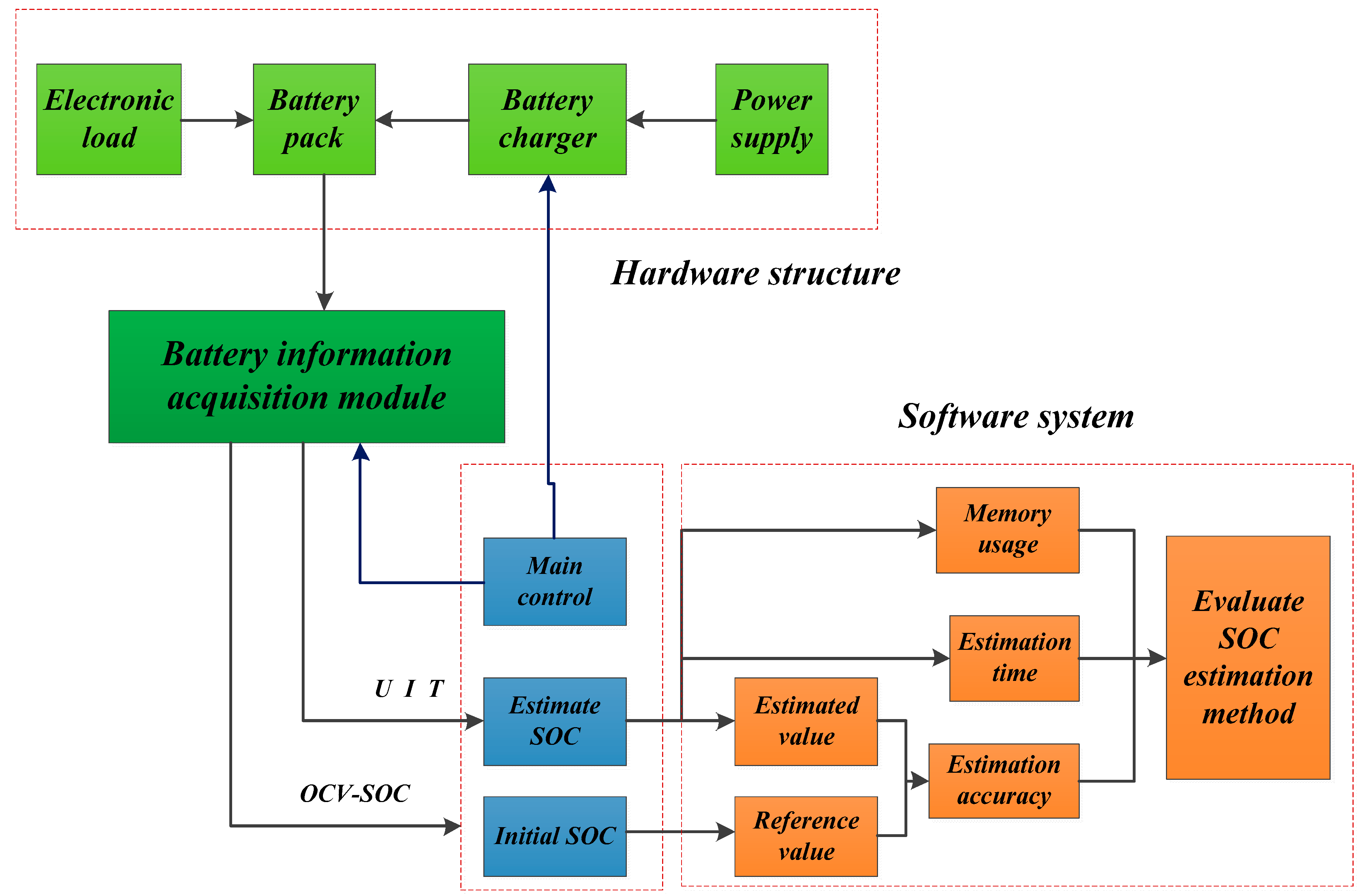
Figure 1. The overall design scheme of the verification platform.
Energies 15 03221 g001
Figure 2. The hardware structure design of the verification platform.
Energies 15 03221 g002
Figure 3. The hardware structure diagram of the main control board.
Energies 15 03221 g003
Figure 4. The hardware structure diagram of the slave control board.
Energies 15 03221 g004
Figure 5. The hardware structure diagram of the temperature control board.
Energies 15 03221 g005
Figure 6. The schematic diagram of the battery pack.
Energies 15 03221 g006
Figure 7. The battery charger GSADBAT-750W75S.
Energies 15 03221 g007
Figure 8. Programmable electronic load IT8512A+.
Energies 15 03221 g008
Figure 9. The energy information flow of the verification platform.
Energies 15 03221 g009
Figure 10. Verification and evaluation process of the SOC estimation method.
Energies 15 03221 g010
Figure 11. Different battery pack structures.
Energies 15 03221 g011
Figure 12. Initial interface of the upper computer software.
Energies 15 03221 g012
Figure 13. Verification results of the real-time SOC estimation.
Energies 15 03221 g013
Figure 14. Verification results of the offline SOC estimation.
Energies 15 03221 g014
Table 1. The functional parameters of the BMS slave monitoring circuit.
ProjectsParameters
Operating voltage range19 V~34 V
Operating temperature range−40 °C~85 °C
Operating humidity range0~85%
Voltage monitoring range of battery cell0 V~5 V
Voltage sampling accuracy of battery cell≤±1 mV
Sampling frequency of cell voltage<30 mS
Total voltage monitoring range20 V–150 V
Total voltage monitoring accuracy≤0.5% FSR
Temperature measurement range−40 °C~125 °C
Temperature measurement accuracy<±1 °C
Current monitoring range−40 A~40 A
Current monitoring accuracy≤±40 mA (<0.1%)
Current sampling frequency≥50 Hz
Balanced control modePassive equilibrium
Number of external CAN interfaces2 channels
Number of main control relay control channels5 channels
Table 2. Verification platform communication protocols summary.
EquipmentAvailable ProtocolsFinal Selected Protocols
Programmable electronic loadRS232RS232
RS485
DisplayRS232RS232
RS485
Battery chargerRS485RS485
Upper computerRS232RS232
Main control boardCANCAN
Temperature control boardRS232RS232
Voltage acquisitionSPISPI
Current acquisitionSPISPI
Temperature acquisitionSPISPI
Publisher’s Note: MDPI stays neutral with regard to jurisdictional claims in published maps and institutional affiliations.