Article

Interactions between Seismic Safety and Energy Efficiency for Masonry Infill Walls: A Shift of the Paradigm

1
CONSTRUCT-LESE, Department of Civil Engineering, Faculty of Engineering, University of Porto, 4200-465 Porto, Portugal
2
RISCO, Department of Civil Engineering, University of Aveiro, 3810-193 Aveiro, Portugal
*
Authors to whom correspondence should be addressed.
Energies 2022, 15(9), 3269; https://doi.org/10.3390/en15093269
Submission received: 13 April 2022 / Revised: 27 April 2022 / Accepted: 27 April 2022 / Published: 29 April 2022
(This article belongs to the Special Issue Improving the Energy Efficiency of Buildings)

Abstract

:
Currently, the upgrade of existing reinforced concrete (RC) buildings focuses only on energy retrofitting measures due to the current policies promoted in the scope of the European Green Deal. However, the structural deficiencies are not eliminated, leaving the building seriously unsafe despite the investment, particularly in seismic-prone regions. Moreover, the envelopes of existing RC buildings are responsible for their energy efficiency and seismic performance, but these two performance indicators are not usually correlated. They are frequently analyzed independently from each other. Based on this motivation, this research aimed to perform a holistic performance assessment of five different types of masonry infill walls (i.e., two non-strengthened walls, two walls with seismic strengthening, and one wall with energy strengthening). This performance assessment was performed in a three-step procedure: (i) energy performance assessment by analyzing the heat transfer coefficient of each wall type; (ii) seismic performance assessment by analyzing the out-of-plane seismic vulnerability; (iii) cost–benefit performance assessment. Therefore, a global analysis was performed, in which the different performance indicators (structural and energy) were evaluated. In addition, a state-of-the-art review regarding strengthening techniques (independent structural strengthening, independent energy strengthening, and combined structural plus energy strengthening) is provided. From this study, it was observed that the use of the external thermal insulation composite system reduced the heat transfer coefficient by about 77%. However, it reduced the wall strength capacity by about 9%. On the other hand, the use of textile-reinforced mortar improved the strength and deformation capacity by about 50% and 236%, but it did not sufficiently reduce the heat transfer coefficient. There is a need to combine both techniques to simultaneously improve the energy and structural energy performance parameters.

1. Introduction

The construction sector is responsible for 36% of carbon dioxide emissions, 40% of the energy consumption, and 55% of the electricity consumption in the European Union (EU) [1]. Most of this energy consumption and carbon dioxide emissions are directly related to building heating and cooling. This fact is justified by the late implementation of the first energy codes for buildings in the EU, which only became official in the 1970s when about 66% of the current EU building stock had already been built [2]. Reducing energy consumption in the building sector can play a crucial part in achieving the goal defined by the United Nations (i.e., reducing emissions of climate-damaging greenhouse gases to zero by 2050) [3]. Currently, several policies are being implemented to carry out a sustainable renovation of existing buildings, focusing only on reducing the operational energy consumption and using low-carbon materials in the refurbishment process [4,5]. However, the structural deficiencies or vulnerabilities are not eliminated, leaving the building seriously unsafe despite the investment, particularly in seismic-prone regions [6]. Structural assessment and structural retrofitting are analyzed independently from functional rehabilitation.
Furthermore, several policies promote only nonstructural rehabilitation, i.e., improving the building functional characteristics in terms of their energy efficiency. On the one hand, it is expected that this approach will improve energy efficiency and reduce carbon dioxide emissions. On the other hand, the structural characteristics of the buildings will remain, thus neglecting this unique opportunity of simultaneously upgrading the structural safety and resilience of the building stock against natural hazards, extreme events, and climate change.
A recent post-earthquake damage survey highlighted the vulnerability of existing building structures [7,8,9,10]. Most of these structures were built before the enforcement of modern seismic codes. Moreover, the seismic response of some nonstructural elements is directly responsible for damages, collapses, casualties, and economic losses, and the impact on post-earthquake rehabilitation costs [11] is estimated to be about 50% of the total repair costs [12]. Around 40% of EU buildings are located in seismic regions and designed with substandard safety requirements, of which 65% of them need both energy and seismic retrofitting. Independent seismic [13] or energy retrofitting interventions [14] are available and are usually adopted. However, a holistic approach comprising the association of structural safety, energy efficiency, and sustainability for upgrading existing buildings is still missing. Likewise, the climate change associated with more frequent extreme weather events is still not covered by the most recent design codes for building renovation and upgrading in EU and non-EU countries. Extreme weather and climate events can lead to disasters with significant impacts on humans and buildings [9]. Furthermore, the type and pattern of extreme events may shift, with alternating floods and droughts in many locations, leading to communities and nations requiring more integrated preparedness to extreme events. As extreme events become more common and more intense, these events themselves will be a factor determining vulnerability to subsequent events. Given the importance of these extreme events, it is surprising that there has been limited attention to this issue in the scientific literature. A deep and critical revision of the building’s structural design codes is mandatory to promote their upgrade, ensuring a proper safe level, considering the increase in the building life cycle. Moreover, understanding the complex nature of storm surge damage is a multifaceted task. Many building features contribute to the vulnerability or resilience of an exposure. Regional differences in building practices and design codes also influence the damage extension caused by a storm surge [15]. Storm surge can cause either structural or nonstructural damage to buildings. Recently, events such as Hurricane Sandy in 2012 [15], which damaged or destroyed over 650,000 structures, have highlighted the significant vulnerability of many susceptible coastal communities. With the adverse effects of sea-level rise and climate change expected to further increase the potential for future flooding, better understanding the impact of storm surge on coastal structures is a critical concern. Engineering studies, claims data, and damage surveys indicate that there can be significant variation in building vulnerability by region and year of construction [16]. This variation is mainly due to modifications in building codes and regional differences in construction practices (e.g., prevalence of basements or elevated first floors). Reliable loss estimation depends on accurately capturing the spatial and temporal differences in vulnerability.
The design, construction, and operation of infrastructure that is more environmentally, socially, and economically responsible over its whole life cycle from cradle to grave are becoming increasingly desirable worldwide. The next generation of building rehabilitation must be designed according to these broad, long-term design goals for the benefit of our planet and the current and future generations of humans, animals, and plants. While the goals of such a sustainable design approach extending over the entire life cycle are well intended, upgrading existing building structures that are socially, environmentally, and economically sustainable is not functionally possible for current structural designers. This is due to the lack of quantitative targets for a “sustainable” design, as well as quantitative metrics for measurement and comparison of structural design [14]. Furthermore, there is a lack of a probabilistic-based design approach translatable to engineering practice expectations of rational design procedures that manage uncertainty in structural design, construction, and use. There is a need for constant seismic monitoring for some structures and even monitoring of civil engineering activities in the near areas. Special structures such as the one mentioned above are also required for probabilistic-based monitoring [17,18].
In addition, current sustainable design approaches do not compare systemic and aleatory uncertainty in engineering design and the costs of reducing that uncertainty. Both fields still lack common language and understanding despite the increasing research and knowledge in recent years on energy efficiency, structural safety, life cycle, and sustainability applied to existing buildings. Combined structural and energy approaches for assessing buildings are seldom observed in upgrading existing buildings. Nevertheless, energy consumption reduction and the increase in structural resilience and mitigation of the existing risks should simultaneously be the key factors guiding the rehabilitation of existing buildings if the objective is to provide a safer, more sustainable built environment.
Additionally, some RC structures are being adapted for special tasks, especially in research, e.g. underground accelerator complexes with new projects in the future will require even higher seismic stability [19].
Upgrading the existing building stock toward being more sustainable, energy-efficient, and resilient is of the utmost importance. The enormous investment planned for the next decade for a sustainable transition to being climate-neutral by 2050 (one billion EUR in the EU) considering the European Green Deal truly reflects the importance of this topic in the future of society. The strategies also need to be aligned with the Sendai framework action plan for disaster risk reduction 2015–2030 and the United Nations 2030 Agenda to accomplish all the goals proposed.
Based on this motivation, this research aimed to perform a holistic performance assessment analysis of five different types of masonry infill walls (i.e., two non-strengthened walls, two walls with seismic strengthening, and one wall with energy strengthening). This preliminary performance assessment was performed in a three-step procedure: (i) energy performance assessment by analyzing the heat transfer coefficient of each wall type; (ii) structural performance assessment by studying the out-of-plane seismic behavior through quasi-static and full-scale tests; (iii) cost–benefit performance assessment by comparing the costs of each type of wall as a function of structural and/or energy performance. A global analysis is provided, in which the different performance indicators (structural and energy) are evaluated. In addition, a state-of-the-art review regarding strengthening techniques (independent structural strengthening, independent energy strengthening, and combined structural plus energy strengthening) is provided.
The novelty of this research work deals with identifying the current needs and limitations in the retrofitting of infill walls toward supporting the creation of future synergies between the structural and energy demands for holistic rehabilitation and retrofitting.

2. Review of Retrofitting Techniques for Masonry Infill Walls

Masonry infill walls comprise a significant fraction of a building envelope and are used for different purposes: (i) providing thermal comfort, (ii) providing acoustic comfort within a building without compromising its aesthetics, and (iii) for architectural purposes. The thermal resistance of infill walls heavily influences the building energy consumption, especially in high-rise buildings where the ratio between the infill walls and total envelope area is high [2]. The sustainable renovation of existing infilled reinforced concrete buildings is typically addressed, focusing only on reducing the operational energy consumption and the use of low-carbon materials in the refurbishment process. The structural deficiencies are not eliminated, leaving the building seriously unsafe despite the investment, particularly in seismic-prone regions [6].
Several efforts have been made to propose efficient techniques to improve the energy efficiency of buildings, focusing only on the upgrade of the masonry infill walls, such as green walls, naturally ventilated façades, systems of interior insulation by cladding, thermal insulation of external wall air chambers, kit systems, prefabricated units, external insulation of party wall, external thermal insulation composite systems, and cement panels. Some of them are suitable for rehabilitating existing buildings, and others are only possible for new buildings.
At the same time, in the sequence of multiple earthquakes, different structural retrofitting techniques have been proposed to reduce the seismic vulnerability of the masonry infill walls. The scientific community’s concerns are related to validating the technique’s efficiency when subjected to in-plane and out-of-plane seismic loadings.
The current needs and priorities to improve the energy efficiency of buildings, making them more sustainable and reducing the seismic vulnerability in seismic-prone regions, enhance the demand for combined energy and structural retrofitting. Reducing the seismic vulnerability of masonry infill walls will save several human lives and economic losses. It will directly impact the construction sustainability since it will no longer be needed to replace or repair them. The most reasonable strategy to achieve these objectives is to combine existing techniques commonly used independently. This strategy will soon be possible to improve the energy efficiency and seismic behavior of buildings in a single intervention (see Figure 1).
The way that the performance assessment of buildings is currently performed may need to be rethought toward a holistic performance assessment. The creation of synergies between the energy and structural sector will optimize the retrofitting interventions of existing buildings. The subsections below help support the discussion of a possible combination of structural and energy retrofitting techniques for masonry infill walls.

2.1. Structural Retrofitting Techniques

The structural retrofitting of masonry infill walls should prioritize preventing the collapse of the wall during an earthquake. As previously mentioned, the wall is subjected to two types of loading demands during a seismic event: loadings along the wall plane (i.e., in-plane seismic loadings) and loadings perpendicular to the wall plane (i.e., out-of-plane seismic loadings). When subjected to in-plane loadings, the masonry infill walls can reach different levels of damage. For low seismic demands, the first is the detachment of the wall from the surrounding frame [7]. During this stage, the detachment in the top interface of the wall is particularly visible. Then, with the increase in seismic demand, the wall can reach two different types of failure mechanism, which can also coincide: diagonal cracking that corresponds to a crack developed due to high tension stresses through in-plane demand [20] or shear failure that corresponds to horizontal cracks normally visible in the middle of the wall due to sliding along vertical joints. These failure mechanisms depend on the wall type, i.e., masonry unit, mortar, wall geometry, and slenderness. Corner crushing can also occur due to the stress concentration in the wall corners.
The out-of-plane seismic behavior of walls represents a particular vulnerability, as several total or partial collapses have been reported in the sequence of earthquakes [21]. Different studies were developed to investigate the key parameters that can potentiate the collapse mechanism of the wall. The most important one seems to be the interaction between the in-plane and out-of-plane seismic demands. The in-plane demands reduce the out-of-plane resistance since they damage the wall boundary conditions, which are fundamental in the out-of-plane performance [22,23,24]. The reduction in wall support width caused by the partial support of the wall for thermal insulation disposition significantly reduces the wall strength and displacement capacity [19]. Other aspects such as wall slenderness, openings, workmanship, and type of masonry units can also modify the wall out-of-plane performance [25,26].
Thus, a structural retrofitting for masonry infill walls should prioritize preventing the collapse due to out-of-plane loadings for human safety. The second priority needs to be to provide to the wall capacity to delay the damage evolution and, thus, increase the wall displacement capacity under both in-plane and out-of-plane loadings. The increase in the wall energy dissipation capacity for both in-plane and out-of-plane loadings would lead to local and global (i.e., the building) benefits.
According to the literature, two different strategies can be assumed for the structural retrofitting of infill walls. The first strategy consists of disconnecting the wall from the structural system. This strategy is particularly focused on the effect of the wall on the whole global seismic behavior of the building. The presence of the infill walls in reinforced concrete buildings causes an increase in their lateral stiffness, reduces their natural period, and causes an increase in the expected seismic loading [27,28]. It was evident in recent earthquakes that the walls were responsible for global failure mechanisms such as soft-story and short-column mechanisms that caused the building collapse [29]. With this retrofitting strategy, the in-plane influence of the walls on the global seismic response is prevented, and their influence on the building behavior is quite reduced (i.e., only their dead load remains). However, from the out-of-plane point of view, this strategy can highly increase the probability of collapse of the wall since the wall is not connected to the frame structure and the arching mechanism, which is one of the key aspects for the wall out-of-plane resistance. The disconnection of the wall from the surrounding structure can be achieved by using sliding devices [30,31]. This technique provides some capacity to the wall for dissipating energy and deforming, which is why these panels are called “engineered walls”. Alternatively, energy dissipation devices can be included, disconnecting the wall from the frame structure [32]. The main purpose is to dissipate the energy during the seismic event and have an easily replaceable device, if necessary, in a post-earthquake scenario. However, it should be noted that the design of this energy dissipation device requires adequate methodologies that consider the wall in-plane and out-of-plane behavior [33]. The third alternative is to disconnect the wall from the structure through gaps, which is somewhat adopted in New Zealand, Japan, Turkey, and some states in the USA.
The second strategy effectively strengthens the wall and connects it to the building superstructure. Different techniques can be used within this strategy, such as engineered cementitious composites (ECCs), textile-reinforced mortars (TRMs), fiber-reinforced polymers (FRPs), ferrocement, and bed joint reinforcement.
FRP consists of a composite material made of a polymer matrix reinforced with fibers. Different materials are used for the FRP fibers, such as carbon, glass, aramid, wood, and paper. The polymer is usually an epoxy, vinylester, or polyester thermosetting plastic, while phenol formaldehyde resins are still used. The applicability of FRP to concrete or masonry structures as a substitute for steel bars or prestressing tendons has been actively studied in numerous research laboratories and professional organizations around the world. FRP strengthening offers several advantages such as corrosion resistance, nonmagnetic properties, high tensile strength, lightweight, and ease of handling. However, it generally provides a linear elastic response in tension up to failure (described as brittle failure) and a relatively poor transverse or shear resistance [34]. This technique has poor resistance when exposed to fire or high temperatures. FRP also presents some significant strength upon bending and is sensitive to stress-rupture effects. Moreover, it is highly costly when compared to other conventional techniques. This technique is only effective against out-of-plane loading if a proper connection of the FRP to the reinforced concrete elements is ensured [35,36].
ECC is a mortar-based composite reinforced with specially selected random fibers. The fibers can be made of steel, polymer, or carbon. One of the main advantages of using ECC is the possibility of reaching high tensile strength and strain levels. Some studies focused on the strengthening of infill walls with ECC against in-plane and out-of-plane seismic loadings [37,38], showing that special attention must be given to assure an adequate bond between the ECC and the wall surface. Furthermore, priority must be given to connecting the ECC to the RC frame elements. These studies proved that the absence of adequate anchorage decreases the ECC strengthening effectiveness.
The TRM combines the use of reinforcing meshes with mortar layers that can have standard properties or high strength and/or ductility characteristics [39]. The factors that can affect the TRM efficiency are the connection of the mesh to the RC frame elements, the mesh tensile strength and strain capacity, fiber slenderness and length, and the size of aggregates that compose the mortar matrix. Different types of connectors are available to fix the strengthening material to the reinforced concrete elements, such as plastic connectors, L-shaped glass FRP connectors, steel connectors, and FRP rods [40]. In these studies, this technique proved to be efficient in preventing the collapse of infill walls [41,42]. In addition, it is relatively cheaper and easy to apply, which makes it a solution with a high potential for application.
Another alternative is the application of ferrocement that consists of wire meshes and cement mortar. Some experimental studies were carried out to validate the efficiency of this technique [43,44,45,46,47,48]. However, it should be mentioned that this strengthening technique typically requires the strengthening of the adjacent RC elements, which significantly increases the labor costs. At the same time, the global frame behavior is drastically modified, which should be taken into account in the global analysis of the building structure.
Table 1 summarizes the available structural retrofitting techniques, including the types of buildings for the which they are recommended (existing or/and new buildings). The cost of implementation, return period, and compatibility with structural retrofitting are quantified from very low to very high. The cost of implementation was based on the current prices in the Portuguese construction industry market. The return period informed in Table 1 is the value suggested by the supplier.
Regarding the cost of implementation, the lowest-cost solution is textile-reinforced mortar, while the most expensive ones involve the inclusion of sliding devices or energy dissipation devices. All retrofitting techniques present medium to high return periods. Lastly, the techniques most compatible with energy retrofitting solutions are textile-reinforced mortars, fiber-reinforced polymers, and engineering cementitious composites.

2.2. Energy Retrofitting Techniques

The energy efficiency of a specific building can be improved by improving its envelope, including the walls, floor, roof, windows, and doors. Since the scope of this manuscript only deals with the masonry infill walls, the review of technologies developed for floors, roofs, windows, and doors are excluded from this study.
The construction industry has worked hard on developing energy strengthening solutions for masonry infill walls located in the building envelope. The most known one is the external thermal insulation of the building’s envelope. Some other approaches consider insulation in the inner wall surface of the building envelope.
The external thermal insulation retrofitting of a building is usually regarded more efficient than inner surface retrofitting when only focusing on the thermal improvement, i.e., increasing the thermal resistance and, thus, reducing the thermal transmittance of the building envelope and respecting the thermal bridge reduction. Therefore, if possible, priority should be given to retrofitting the walls located in the building’s envelope. In contrast, the roof and especially the floor toward the ground may be rather challenging to retrofit exteriorly in a cost-effective way.
One of the main advantages of applying external thermal insulation retrofitting is that it is less inconvenient and complex for the building occupants when compared to retrofitting the internal walls, and it is more efficient with respect to eliminating/reducing the thermal bridges. The application of external thermal insulation protects the building’s existing original façade against climate exposure (e.g., wind, snow, rain, solar radiation, and temperature variation). It does not affect the indoor living area (in contrast with the inner wall surface retrofitting approach). Internal wall retrofitting would have enormous implications in the daily routine of the building occupants, with the possibility of occupants staying in the building during these interventions typically being avoided. Another negative consequence is the reduction in thermal inertia and the consequent decreases in internal heat storage capacity and delay of heat transfer inside the building.
Concerning the disadvantages of external thermal insulation retrofitting, the restrictions for changing or modifying an exterior facade or roof in the case of heritage buildings (i.e., churches, castles, etc.) can be highlighted. Due to the characteristics of these types of interventions, it may not be easy to keep the aspect of the original façades in terms of architecture or visual design. The application of external retrofitting is also limited, like many other interventions in the construction industry, taking into consideration the climate conditions, i.e., weather, or extreme events. Another restriction is related to the additional costs with the erection of scaffolding and similar equipment to allow the safe development of retrofit activities in external façades.
The most known energy retrofitting technique is the external thermal insulation composite system (ETICS). ETICS is an external thermal insulation system for external walls, installed as a group of layers including an insulating panel, reinforcement layer, and finishing coating with an external protective plaster. These are fastened to the supporting wall with an adhesive material and/or a mechanical fixture. In this way, ETICS integrates insulation and sheathing layers in a single system that can be used for constructing new building or for refurbishing existing ones. As one of its additional features, by using a continuous perimeter of the external insulation, ETICS can avoid thermal bridges. Different types of insulation layer materials can be used in ETICS, such as EPS, XPS, and cork. Figure 2 presents examples of the application of ETICS in walls in a laboratory and a two-story reinforced concrete building. The textile meshes used in this technique are nonstructural meshes with low tensile strength, a small grid, and medium to high elasticity. Plastic connectors fix the ETICS to the wall substrate and to the envelope RC elements (i.e., beams, columns, slabs). The ETICS system allows sufficient mitigation of temperature fluctuations in the supporting walls, thus reducing material stresses and the danger of cladding ruptures due to temperature-driven expansions and contractions of the wall material [49,50].
A party wall is a dividing partition, usually a structural one, consisting of two adjoining walls built at different times between two adjacent buildings. External insulation of a party wall is applicable either in the case of existing buildings sharing an exterior wall or when there is demolition of an adjacent building. It is applicable even when important deficiencies in the finish of the facade, such as holes, lack of sealing and waterproofing, and inconsistent or absent thermal insulation, may arise [51]. The application of polyurethane foam refurbishes the party walls by improving the sealing, impermeability, and consistency of thermal insulation. To prevent the adverse effect of UV rays, the polyurethane foam must be protected with a layer of paint or a highly dense polyurethane elastomer, which will also improve the features of this solution. Another strategy available is using prefabricated units for external wall insulation (called “kit systems”) comprising external skin, an insulating layer (which can be made of different materials, such as XPS, EPS, PF, or PUR), and fixing devices. This type of solution is prefabricated and delivered as a single product that is ready to be installed on site [52].
Cement panels for façade refurbishment are also used. This type of technique comprises a galvanized steel or aluminum support structure attached to the supporting wall substrate, bearing a cement panel with a decorative coating. If external intervention is not possible, internal thermal insulation is a feasible solution. As previously discussed, the main disadvantage is reducing the living area. Furthermore, the complexity for the occupants of the building during the retrofitting process should not be neglected. The thermal insulation of external walls by injecting insulation material, such as mineral fibers, into chambers or cavities present in external walls is also an efficient technique [53]. Lastly, more sustainable, and green solutions are naturally ventilated façades [54,55] and green walls [56,57,58]. Table 2 summarizes the available energy retrofitting techniques, including the types of buildings for which they are recommended (existing or/and new buildings). The cost of implementation, return period, and compatibility with structural retrofitting are quantified from very low to very high. The cost of implementation was based on the current prices in the Portuguese construction industry market. The return period informed in Table 2 is the value suggested by the supplier. From the analysis of the different available techniques, it can be seen that the most expensive one involves the use of cement panel for façades refurbishment. The cheapest one involves the thermal insulation of external walls by injecting insulation material, but it is not suitable for every type of building.
Naturally ventilated façades, green walls, thermal insulation of external walls by injecting insulation material, and cement panels for façade refurbishment have a high expected return period. However, it should be stressed that the remaining techniques do not have a considerably lower return period. Some of the solutions may have higher maintenance requirements during their lifespan.
The compatibility with structural retrofitting was also addressed for each technique. The analysis concluded that there is excellent compatibility for external thermal insulation composite systems and internal thermal insulation. For example, incorporating textile meshes with high tensile strength may upgrade these techniques to other structural resistance levels (i.e., increasing seismic strength and displacement capacity). In all these techniques, the principal key is related to the connectors used to fix the strengthening material to the wall substrate or reinforced concrete elements, as observed in Section 2.3. It should be noted that the compatibility of internal energy retrofitting with structural strengthening may not result in a very efficient solution. The anchorage of the wall and retrofitting material is more complex and may face internal obstacles such as cabinets and electrical plugs.

2.3. Structural Plus Energy Retrofitting Techniques

Manos et al. [59] studied the structural performance of masonry infill walls strengthened with external thermal insulation composite systems. A set of masonry infill walls were subjected to flexural strength loadings. Later, Manos et al. [60] investigated the in-plane performance of the same thermal insulation composite system. Diagonal compression tests were carried out on prototype specimens to study the influence of thermal insulation on the in-plane behavior of clay brick masonry panels with or without thermal insulation. It was concluded that the panels strengthened by thermal insulation did not collapse, even when the wall reached large out-of-plane displacements, due to the protective action of the used plastic anchors. The authors also concluded that the presence of connectors increased the out-of-plane flexural capacity and prevented brittle behavior compared to the non-strengthened configuration. Nonetheless, the influence of the condition of the connectors along the wall boundary conditions needs to be studied in future investigations.
Recent studies focused on testing the efficiency of combining structural plus energy retrofitting techniques. The technique selected in all studies consisted of upgrading the textile-reinforced mortar with thermal insulation materials, such as the thermal insulation composite system [2].
Karlos et al. [61] carried out a series of medium-scale tests on masonry walls subjected to out-of-plane cyclic loadings. The authors investigated the effect of placing the TRM in a sandwich form (over and under the insulation) or outside the insulation, in addition to one-sided or two-sided TRM jacketing. The combined TRM with thermal energy insulation scheme was quite effective when the wall was subjected to out-of-plane loadings if proper bonding between the different layers was achieved. It was also observed that positioning the reinforcement outside the thermal insulation improved the wall strength and deformation capacity compared to TRM alone.
Gkournelos et al. [62] tested 12 walls retrofitted with textile-reinforced mortar combined or not with expanded polystyrene as a thermal insulation material. Each test consisted of in-plane diagonal compression and out-of-plane bending on walls with or without prior in-plane damage. Masonry walls featuring both textile-reinforced mortar and thermal insulation, with no prior in-plane damage, reached more than 25% out-of-plane strength and 50% deformation at peak load. The authors claimed that the better performance was not due to the insulation material itself, but the higher effective depth of the textile-reinforced mortar, due to the presence of thermal insulation. During the tests, it was observed that the beneficial effect of increased effective depth was counterbalanced by premature shear/debonding failure due to cracking due to the in-plane loading.
Another alternative strategy for simultaneously achieving structural plus energy retrofitting was proposed by Artino et al. [63]. The strategy consisted of replacing the external infill walls, made of hollow bricks, with high-performing autoclaved aerated concrete blocks. The authors assessed the efficiency of this technique using a four-story building as a case study. They concluded that the proposed intervention involves the greatest improvement in the limit state of damage limitation from a structural viewpoint. At the same time, lower upgrades were recorded at the limit states of life safety and near collapse. Concerning energy efficiency, the energy demand could be reduced by 10% and 4% for heating and cooling, respectively, just by replacing the building envelope walls.

3. Methodology and Specimen Description

3.1. Specimen Description

This section aimed to assess the structural and energy performance of different types of infill masonry walls. A prototype infilled RC frame was selected comprising two RC columns, two RC beams, and one infill wall. The specimen geometric characteristics were based on an extensive survey carried out on the Portuguese building stock by Furtado et al. [64], where a database of 80 infilled RC buildings was generated, including geometric features of the structural (i.e., columns and beams) and nonstructural (i.e., masonry infill walls) elements.
Therefore, the geometry of the RC specimen was defined to have an inter-story height of 2.80 m (i.e., the vertical distance between beam–column joints) and a span of 4.50 m (i.e., the horizontal distance between beam–column joints). The frame was designed according to Eurocode 8 [1] recommendations for the medium ductility class. The column dimensions were 0.30 × 0.30 m2 with longitudinal reinforcement equal to 4ø16 + 2ø12 and transversal reinforcement equal to ø8//0.05 m within the plastic hinge regions and ø8//0.15 m in the remaining extension of the column. Regarding the beam cross-section detailing, it was defined to be 0.30 × 0.50 m2 with symmetrical longitudinal reinforcement of 5ø16 + 5ø16 and transversal reinforcement of ø8//0.10 m along the plastic hinge length and ø8//0.20 m in the remaining beam extension. Thus, the wall geometry was defined as 4.20 m in length by 2.30 m in height. The details of the prototype frame are shown in Figure 3
Five different types of masonry infill walls were selected for the present study based on three criteria (i) type of masonry unit, (ii) structural strengthening, and (iii) seismic strengthening. The following types were considered:
  • Type 1: masonry infill walls made of hollow clay horizontal brick units (length, height, and thickness of 300 × 200 × 150 mm3, respectively), 1 cm of plaster; no mechanical connection to the envelope RC elements, and no gaps between the wall and the frame, with no seismic strengthening and no energy strengthening. A detailed schematic of this typology is shown in Figure 4a;
  • Type 2: masonry infill walls made of hollow clay horizontal brick units (the same as type 1), 2 cm of plaster, no gaps between the wall and the frame, and no mechanical connection to the envelope RC elements, with seismic strengthening (i.e., textile-reinforced mortar solution) but no energy strengthening. Figure 4b presents a detailed schematic of this infill wall typology;
  • Type 3: masonry infill walls made of hollow clay horizontal brick units (the same as type 1), 1 cm of plaster, no gaps between the wall and the frame, no mechanical connection to the envelope RC elements, and no seismic strengthening, but with energy strengthening (i.e., external thermal energy insulation). A detailed schematic of this typology is shown in Figure 4c;
  • Type 4: masonry infill walls made of vertical hollow lightweight concrete brick units with a geometry of 400 × 190 × 315 mm3 (length, height, and thickness, respectively), no plaster, no gaps between the wall and the frame, no mechanical connection to the envelope RC elements, no seismic strengthening, and no energy strengthening, but masonry units with improved energy properties. A detailed schematic of this wall typology is shown in Figure 4d;
  • Type 5: masonry infill walls made of vertical hollow lightweight concrete brick units (the same as type 4), 2 cm of plaster, no gaps between the wall and the frame, and no mechanical connection to the envelope RC elements, with seismic strengthening (i.e., textile-reinforced mortar) but no energy strengthening, and masonry units with improved energy properties (i.e., lower heat transfer coefficient (Uvalue)). A detailed schematic of this masonry infill wall typology is shown in Figure 4e.
All designs were selected as possible solutions for walls presented in the envelopes of RC buildings, representative of southern European countries. The out-of-plane seismic behavior of types 1 and 2 was previously studied by Furtado, et al. [39], while that of types 4 and 5 was studied by Agante, et al. [65]. Nonetheless, the Uvalue and construction costs of these masonry infill walls has not yet been studied in the literature.

3.2. Construction Procedure

Specialized operators built all masonry infill walls according to common construction practice. As previously mentioned, no mechanical connections were used to link the walls to the envelope RC elements. Moreover, no gaps or openings were considered for this specific study.
The wall types 1, 2, and 3 were built using hollow clay horizontal brick units 150 mm thick. Each masonry unit had a self-weight equal to 5.2 kg/unit, a percentage of voids equal to 80.5%, and thermal resistance (Rvalue) equivalent to 0.57, 0.58, and 2.54 m2·K·W−1. Compression strength tests were performed on several masonry units according to the standard NP EN 771-1 [66]. An average compressive strength of 1.04 MPa was obtained with a coefficient of variation of 23.6%. A traditional M5 class mortar was used for the construction of the walls.
Concerning wall type 1, a 1 cm plaster was applied to the outer face of the wall and partially applied to the RC elements (15 cm extension over each element). The plaster was not applied over the entire exterior surface of the RC frame since the main goal in the laboratory was to study the out-of-plane behavior of the masonry infill walls. A perspective of the construction evolution of wall type 1 is shown in Figure 5a.
Wall type 2 consisted of a specimen strengthened with a textile-reinforced mortar solution. Twenty-seven days after the construction of the wall, strengthening was performed. A bidirectional fiberglass reinforcing mesh was selected with a 16.7 × 16.7 mm2 matrix, a weight of 185 g/m2, a nominal tensile strength equal to 40.0 kN/m, and a maximum ultimate strain equal to 3.4%. The strengthening started with the application of 1 cm of plaster over the wall and RC element surface (as shown in Figure 5b). After that, five vertical strips (1 m width) overlapping with each other were applied over the plaster. The application of vertical strips was easier than that of horizontal strips (whose length could differ drastically depending on the bay length). The overlap length used between each vertical strip was 10 cm. The mesh was extended for 15 cm over the beams and columns (as shown in Figure 5b). Then, in the overlapping regions for the transition RC frame infill panel, a duplicated mesh was assumed with an overlap equal to 30 cm (15 cm for the RC frame and 15 cm for the infill panel). The fixation of the mesh to the RC elements was ensured using steel connectors with a steel plate (3 mm thick and 30 mm width) drilled with ϕ8 mm holes. Plastic connectors were used to fix the mesh to the wall surface, as shown in Figure 5b. Strengthening was only applied to the external face of the wall.
Wall type 3 comprised a masonry infill wall with external thermal insulation (ETIC system). After wall construction, a 1 cm layer of plaster was applied over the external surface. Then, several EPS plates with 6 cm thickness were fixed to the wall and RC frame surface using cement glue, as shown in Figure 5c. Each plate had the geometric dimensions of 1 m length by 50 cm height. The wall Rvalue was 2.52 m2·K·W−1. The cement glue had a compressive strength of 4.7 MPa and a thermal conductivity coefficient equal to 0.71 W·m−1·K−1. The thickness used to fix each EPS plate was around 3–5 mm. After fixing all the plates, plastic connectors were used to provide additional anchorage of the plates to the wall and RC frame surface, as shown in Figure 5c. Once again, a 3–5 mm layer of cement glue was applied over the surface of the plate. Therefore, a glass fiber mesh with a geometric grid equal to 3.8 × 4.15 mm2 and a tensile strength of 35 N/mm was placed over the cement glue. At that time, another 5 mm layer of cement glue was applied over the mesh, ensuring a plain surface of the wall, as shown in Figure 5c. It should be underlined that this mesh is usually used to prevent cracking due to temperature variation (i.e., thermal expansion and shrinkage).
Wall type 4 consisted of a wall built with lightweight vertical hollow concrete blocks. This masonry unit was characterized by high thermal inertia and a Uvalue of 0.47 W·m−2·K−1. Each masonry unit had the geometric dimensions of 400 × 190 × 315 mm3 and 11 concrete septs. In the construction of the masonry panels, the methodology indicated by the manufacturer of the blocks was followed, adopting discontinuous settlement joints to guarantee the thermal and acoustic characteristics of this type of wall. The construction of all walls began with a continuous layer of mortar being placed across the entire width of the previously humidified frame, as shown in Figure 5d. Then, blocks were set to align the face of the panel with the front face of the RC frame, leaving 15 mm of the block outside the posterior face of the frame. Discontinuous laying joints, approximately 15 mm thick, were placed using a mortar box supplied by the manufacturer, as shown in Figure 5d. This procedure was repeated until it was impossible to fit another row of blocks, leaving about 130 mm to be filled between the panel and the lower face of the upper beam of the RC frame, as can be seen in Figure 5d. It was decided to close the masonry panel 2 or 3 days after its construction to guarantee stabilization of the deformation of the panel during mortar curing, thereby ensuring the sealing between the upper face of the masonry and the upper beam of the frame. Please note that this strategy was also adopted in the remaining walls. No plaster was used in this wall.
Wall type 5 was constructed using the same methodology as type 4. Twenty-eight days after the construction, the wall was strengthened using a glass fiber mesh with a 4 × 4 cm matrix and a tensile strength equal to 70 kN/m, as shown in Figure 5e. Steel connectors (ϕ6 mm and 8 cm length) ensured the mesh connection to the panel. The mesh–frame connection was established using M8 steel connectors and a steel plate with the exact dimensions of wall type 2, as shown in Figure 5e.

3.3. Material Properties

Before the performance assessment of each wall, it is essential to summarize its material and mechanical properties. These properties are presented in Table 3. The compressive strength of the masonry units was determined by performing experimental tests according to NP EN 771-1 [66]. Flexural and compression strength tests were carried out in mortar specimens according to EN 196-2006 [67].

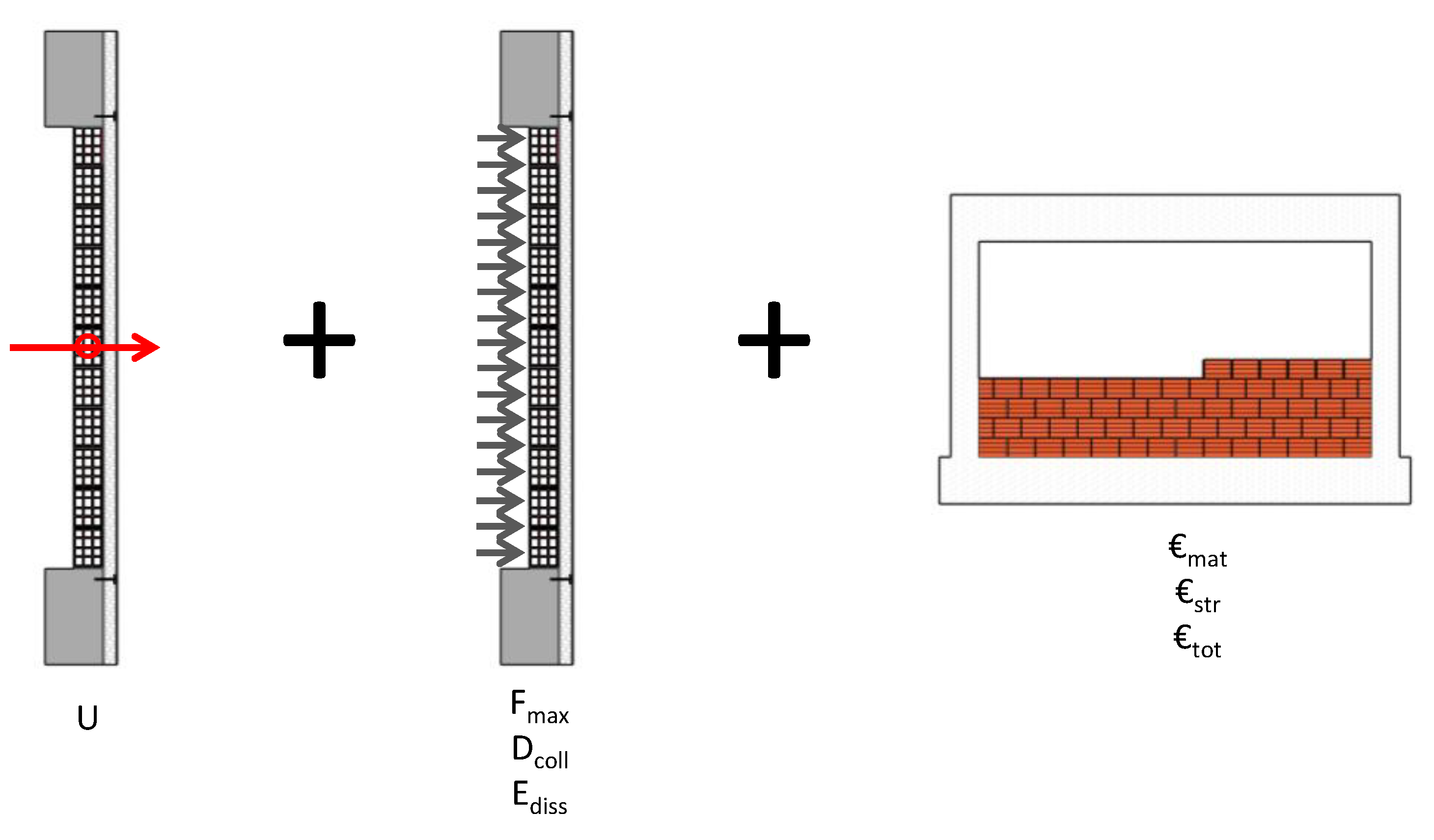
4. Combined Performance Assessment Analysis of Masonry Infill Walls

This performance assessment was conducted in a three-step procedure: (i) energy performance assessment by analyzing the Uvalue of each solution; (ii) structural performance assessment by studying the out-of-plane seismic behavior through quasi-static and full-scale tests; (iii) cost–benefit performance assessment by comparing the costs of each type of wall as a function of their structural and/or energy performance.
The first step consisted of calculating each wall’s Uvalue. The thermal conductivity coefficient (λ) of each material is presented, and the typologies are compared. Then, the second step was related to studying each wall’s out-of-plane seismic behavior. This study was supported by the data results obtained in the experimental testing of each typology. Quasi-static out-of-plane tests were performed in a laboratory. Each test consisted of applying a uniform out-of-plane load over the wall (internal) surface using several pneumatic actuators controlled with pressure cells. The pneumatic actuators were fixed to a steel reaction structure placed behind the RC frame. The steel reaction structure was attached to the RC frame at 12 points, but it was not attached to the strong lab floor. A displacement control was assumed for the tests. The loading protocol consisted of applying half-cyclic OOP displacements (loading–unloading–reloading) that were imposed with steadily increasing displacement levels, targeting the following nominal peak displacements at the control node located in the center of the panel: 0.5, 1, 1.5, 2, 2.5, 3.5, 5, 7.5, and 10 mm, followed by 5 mm increments up to a maximum OOP displacement of 120 mm. Two half-cycles were repeated for each lateral deformation demand level. The main goal was to reach the collapse of the wall. For each specimen, the strength capacity (i.e., maximum out-of-plane force; Fmax), displacement capacity (i.e., displacement for each wall collapse or maximum displacement reached if the wall did not collapse; Dcoll), and energy dissipation capacity (i.e., maximum cumulated energy dissipation; Ediss) were determined.
Concerning the cost analysis (step 3), the cost of each wall component was calculated to understand its impact on the total cost of the wall. Thus, each material cost, €mat, was computed (i.e., masonry units, mortar, material for strengthening, and human resources). The cost of each strengthening solution, €str, was computed. As a result, the total wall cost is presented, and a discussion of the impact of each component is addressed. Figure 6 presents a schematic flowchart of the planned performance analysis and the response parameters under study.

4.1. Energy Performance Assessment

The global heat transfer coefficient defines the overall ability of conductive or convective barriers to transmit heat. This coefficient represents the amount of energy in the form of heat that is applied perpendicularly across an element, with flat and parallel faces, per unit of surface and time, when subjected to a unitary temperature gradient (K) between the environments it separates.
The Uvalue of a building element can be calculated or measured. Knowing the values of thermal conductivity coefficients of the materials that constitute the constructive elements allows for the calculation of its thermal resistance. The Uvalue can be computed using the value of the Rvalue of each component of the masonry wall (i.e., masonry units, coatings, and strengthening material). The Uvalue of a given building element can be calculated according to EN ISO 6946:2017 [68], as given by Equation (1). For this calculation, the values of λ (thermal conductivity coefficient) or Uvalue of each layer are necessary. In this equation, Rsi represents the internal thermal surface resistance (value according to EN ISO 6946:2017 [68]), Rse represents the external thermal surface resistance (value according to EN ISO 6946:2017 [68]), and Rj is the thermal resistance of the layer of each material. For horizontal heat flows, Rsi = 0.13 m2·K·W−1 and Rse = 0.04 m2·K·W−1.
U = 1 R S i + j R j + R S e .
Wall type 1 was composed of hollow, horizontal brick units with 15 cm of thickness and Rvalue = 0.57 m2·K·W−1. In addition, 1 cm of plaster was placed on the external surface of the wall. A thermal conductivity of λ = 1.3 W·m−1·K−1, corresponding to a traditional cement mortar.
Wall type 2 was strengthened with a TRM solution. For the calculation of Uvalue, a TRM thickness of 2 cm and λ = 1.3 W·m−1·K−1 were considered. The mortar used on the plaster of wall type 1 was the same as that used in the TRM applied to wall type 2. The effect of the textile mesh on the energy efficiency of the wall was excluded.
Wall type 3 was first retrofitted with 1 cm of plaster using the same traditional mortar used in wall types 1 and 2 (λ = 1.3 W·m−1·K−1), followed by one EPS layer 6 cm thick with λ = 0.031 W·m−1·K−1. The EPS layers were bound to the support using glue cement mortar with a thickness varying between 3 and 5 mm and thermal conductivity λ = 1.3 W·m−1·K−1. Once again, the effect of the textile mesh on the energy efficiency of the wall was excluded. The reinforcement was completed with a traditional plaster finishing with a thickness equal to 1 cm and λ = 0.3 W·m−1·K−1.
Wall type 4 consisted of lightweight, vertical, hollow concrete blocks with Uvalue = 0.51 W·m−2·K−1. Then, 2 cm of traditional mortar (λ = 1.3 W·m−1·K−1) was used in the TRM strengthening, and the heat transfer coefficient of wall type 5 was calculated.
Figure 7 presents the Uvalue obtained for each type of wall. The highest value (i.e., lowest energy efficiency) was reached by wall type 1, as expected, with Uvalue = 1.76 W·m−2·K−1. The lowest Uvalue (i.e., highest energy efficiency) of 0.40 W·m−2·K−1 was reached by wall type 3, mainly due to the external thermal insulation material. The energy retrofitting reduced Uvalue by about 77%. Wall types 4 and 5 made using masonry units with improved thermal characteristics reached a Uvalue of 0.47 W·m2·K−1.
Compared with the Portuguese Standard in which the maximum Uvalue is established (Portaria n.º 138-I/2021 [69]) for each of the winter climate zones (Table 4), it is possible to state that wall types 1 and 2 can be considered as walls with low energy performance, not complying with the maximum values established by the Portuguese thermal standards. Only wall type 3 complied with I1 and I2, while wall types 4 and 5 complied with I1. None of these walls fit the legal requirements for the most severe winter climate zone in mainland Portugal.
Beyond the comparison with the legal framework, in the scope of this study, wall types 3, 4, and 5 presented higher performance (when compared with types 1 and 2). Again, it is highlighted that this conclusion is only made for the walls under study. Various walls with different types of bricks are considered for energy, structural, or combined energy–structural retrofitting strategies. Walls with higher energy retrofitting will obtain a lower Uvalue. In the same way, walls with lower or no energy retrofitting will obtain a higher Uvalue. Considering the thermal inertia, wall types 1, 2, and 3 had similar values, whereas wall types 4 and 5 exhibited higher values, contributing to better thermal performance due to the decrease in indoor thermal amplitude and higher heat flux delay. Thus, these walls contribute to higher heat flux control, which is directly related to the energy-saving potential, as the heat flux that crosses a constructive element is directly proportional to the wall’s Uvalue. Therefore, a lower Uvalue indicates lower energy losses through the wall. As this study intended to demonstrate the importance of the integrated analysis of thermal and seismic performance, five types of walls were considered. On the other hand, different locations in different climate zones of the country were not considered; this will be addressed in future work, in which the heat flux will be calculated for each situation to determine the relative energy savings.

4.2. Structural Performance Assessment
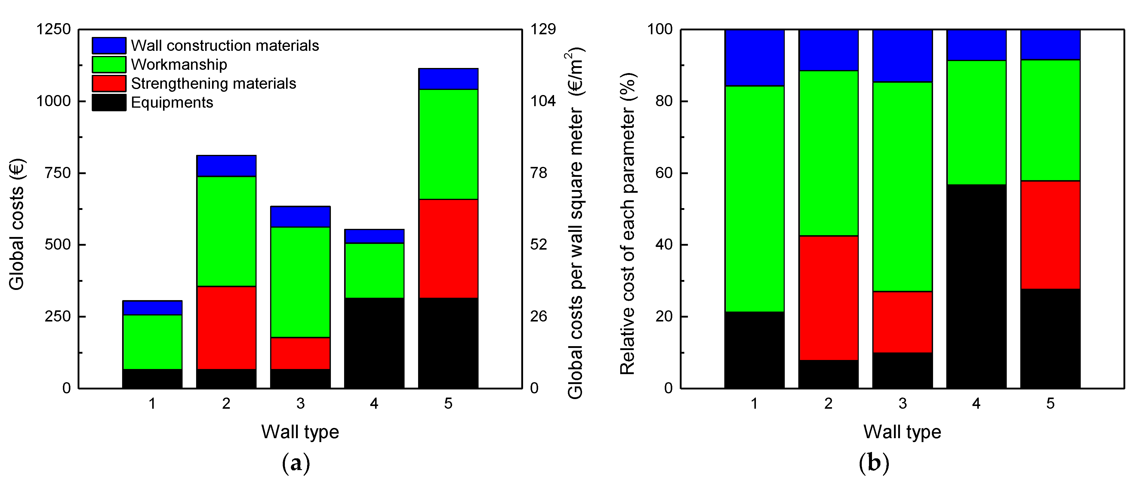
The structural performance was studied herein using force–displacement curves, by directly extracting the parameters Fmax and Dcoll. All response curves are plotted in Figure 8, where the Y-axis indicates both the out-of-plane strength (i.e., the sum of the total out-of-plane force) and the out-of-plane strength factor (i.e., the sum of the entire out-of-plane force divided by the panel surface area of 9.66 m2). The X-axis presents the out-of-plane displacement at the geometric wall center. The drift was computed based on the inter-story height (i.e., 2.3 m) divided per two (i.e., 1.15 m).
A bilinear response curve can be seen from observing the force–displacement curve of wall type 1 (Figure 8a). The initial wall stiffness was 20.32 kN/mm. After reaching the out-of-plane drift of 0.25%, there was a significant drop in the wall stiffness caused by the development of cracks in the wall surface. Trilinear cracking became more visible with a slight wall detachment from the top RC beam. The maximum out-of-plane load of 61.5 kN was reached for a drift of 2.21%. After attaining the peak load, the wall collapsed without decreasing its strength. This test revealed the high seismic vulnerability of this typology, as seen by its fragile behavior. Collapse occurred for a drift of 2.59%.
The behavior of wall type 2 revealed the excellent efficiency of TRM strengthening, as collapse was prevented. The trilinear response curve can be observed in Figure 8b, where three phases can be identified. The first elastic stage occurred when the wall presented an initial stiffness of 80.92 kN/mm. The second stage occurred between the wall’s initial cracking (i.e., drift equal to 0.17% and force of 59.1 kN) and the maximum load of 92.30 kN (i.e., drift equal to 2.55%). The third stage occurred between the peak load and the last displacement reached by the wall (i.e., drift equal to 8.69%). It should be stressed that the test was interrupted before collapse occurred due to the limitation of pneumatic actuators. Nevertheless, the level of deformation reached by the wall was quite significant (higher than half of the wall thickness). The decrease in strength after peak load was due to the crushing of the masonry units, visible on the back surface of the wall. The cracking pattern observed was pure trilinear cracking.
The wall type 3 response curve is shown in Figure 8c. The wall had an initial stiffness of 19.36 kN/mm. After reaching a drift of 0.61%, a strength reduction occurred from 43.9 kN to 33.62 kN due to the slight detachment of wall connectors. The wall began to behave like a rigid body from that moment onward. The arching mechanism increased the wall strength to 55.85 kN for a drift of 5.19%. After the peak load, the subsequent displacement cycle registered an 11% strength decrease with a visible detachment of the wall from the envelope RC frame. Then, the wall collapsed as a rigid body. It is evident that the plastic connectors did not ensure a proper anchorage of the energy-strengthening material to the frame. This deficiency associated with the plastic connectors was previously reported by other authors [40].
The behavior of wall types 4 and 5 was completely different from the previous ones. The considerable thickness of the masonry units played a significant role in the wall out-of-plane response, since it contributed to the double-arching mechanism, resulting in high strength. Accordingly, the vertical scale of wall types 4 and 5 differs from the previous ones (i.e., up to 300 kN instead of 100 kN), as shown in Figure 8d,e.
Wall type 4 started with an initial stiffness of 24.02 kN/mm until reaching a drift of 1.55%, before subsequently reducing its stiffness when initial cracking occurred. Therefore, the strength increased to 229.8 kN for a drift of 4.16%. Then, the force decreased slightly up to 7.64% of drift. The residual strength was 151 kN, as shown in Figure 8d. Like wall type 2, the collapse did not occur due to the limitation of pneumatic actuators. Again, trilinear cracking with a slight detachment of the wall from the top RC beam was observed.
Once again, the efficiency of TRM strengthening was evident in the response of wall type 5, as shown in Figure 8e. Here, a tetralinear response curve was observed, corresponding to initial elastic stiffness (state 1), a small stiffness drops until reaching the peak load (stage 2), a strength reduction to 80% of the peak load (stage 3), and a more considerable strength reduction until the interruption of the test (stage 4). The initial stiffness of the wall was 69.3 kN/mm until a drift of 1.53%. Then, the first crack developed, leading to a slight reduction in the wall stiffness. A peak load of 281 kN was reached for a drift of 2.76%. Subsequently, the out-of-plane force was reduced to 103.6 kN for a drift of 8.21%.
A significant strength capacity difference can be observed when comparing walls made of hollow clay units with those made of lightweight concrete units. Wall types 4 and 5 achieved the highest out-of-plane strength results, quite different from walls 1 and 2 (Figure 9a). It was observed that wall type 2 with seismic retrofitting obtained an out-of-plane strength 50% higher than the reference wall (i.e., type 1). The wall with energy retrofitting (i.e., type 3) reached an out-of-plane strength 8% lower than the reference wall, proving that this retrofitting did not improve the structural wall capacity. Wall type 4 reached an out-of-plane resistance 3.74 times higher than wall type 1, suggesting that larger masonry units may be an interesting solution for achieving walls with high out-of-plane strength. The textile-reinforced mortar strengthening improved the strength of wall type 5 by about 22% compared with the non-retrofitted configuration wall type 4.
The seismic coefficient (i.e., force divided by the wall mass) was computed for each wall, as shown in Figure 9b. For this calculation, the mass of each panel was estimated. The values found for the mass of wall types 1, 2, 3, 4, and 5 were 1270 kg, 1560 kg, 1420 kg, 2840 kg, and 3240 kg. The differences observed in terms of out-of-plane strength were not so high in terms of the seismic coefficient. This is mainly justified by the high mass of wall types 4 and 5. Wall type 2 reached a seismic coefficient 20% higher than wall type 1. Wall type 3 reached a seismic coefficient 19% lower than wall type 1. Furthermore, wall type 4 reached a seismic coefficient 65% higher than wall type 1. The TRM improved the seismic coefficient of wall type 5 by about 8% when compared with wall type 4. Concerning the wall drift at peak load, as shown in Figure 9c, the highest value was obtained by wall type 3, while the lowest value was obtained by wall type 1.
Lastly, the wall drift at the collapse stage (i.e., wall types 1, 2, and 3) or ultimate stage (i.e., wall types 4 and 5) is shown in Figure 9d. It can be observed that all retrofitting solutions (both seismic and energy) improved the wall deformation capacity. The TRM improved the deformation capacity of wall type 2 about 3.36-fold. The energy retrofitting improved the deformation capacity about 2.16-fold.
The cumulative energy dissipation in each masonry infill wall can be computed as the internal area of the OOP force–drift response curve. This response parameter allows analyzing the ability of the infill walls to dissipate the energy induced by the seismic action.
Figure 10 presents the cumulative energy dissipation found in the out-of-plane tests. Once again, better results were obtained by wall types 4 and 5. These walls dissipated more energy than the remaining ones, with a value between 150% and 450%. The comparison between wall types 1 and 2 shows that the strengthening of textile-reinforced mortar improved the energy dissipation capacity up to twofold. On the other hand, energy retrofitting (i.e., wall type 3) did not improve the energy dissipation capacity.
E cum = F OOP d OOP

4.3. Cost Analysis

This section presents a quantification of the costs of each wall type, namely, material costs (wall construction and strengthening), workmanship costs, and equipment costs. The total costs of each parameter are presented in Table 5 The global cost of each type of wall was computed by summing the material, workmanship, and equipment costs. The cost per square meter (unit cost) of each wall was obtained by dividing the global costs per wall area (9.66 m2). Please note that the costs presented herein were computed according to the Portuguese construction prices in 2021.
Figure 11 presents the global costs and the relative cost of each parameter (i.e., material, workmanship, and equipment costs). It is possible to observe that the most expensive wall was type 5, while the cheapest wall was type 1 (non-strengthened). It is not adequate to directly compare the strengthened wall type 5 with the non-strengthened wall type 1. According to the comparison between non-strengthened walls, it can be observed that the cost of wall type 4 (wall made of a vertical hollow concrete block) was about 78% higher than that of wall type 1 (i.e., wall made of hollow clay horizontal brick units), which is justified by the higher price of the masonry units. Concerning the strengthened walls (wall types 2, 3, and 5), the most expensive was type 5, which was 37% costlier than type 2 and 74% costlier than type 3.
Workmanship seemed to be the most relevant parameter increasing the price of each wall, followed by the strengthening material and the wall construction material, as observed by previous authors.
From the comparison of the wall resistance capacity with the wall cost, it is possible to observe that the wall with the highest OOP strength was type 5, which was also the most expensive one. On the other hand, wall type 3 reached the second highest OOP strength but was the third more expensive wall, right after wall type 2. It should be underlined that the wall with the lowest OOP strength was type 1, which was the cheapest one. Thus, a direct relationship between the wall cost and OOP strength capacity can be concluded.
Lastly, a conclusion concerning the relationship between the cost and the wall heat transfer coefficient could not be drawn, since the most expensive wall type 5 had the second lowest heat transfer coefficient. The second most expensive wall had the second highest thermal energy coefficient, i.e., wall type 2. Hence, it can be stated that this relationship is directly affected by the high price of the strengthening material, which affects the global wall cost. Nevertheless, this strengthening approach does not integrate any energy insulation material.

5. Conclusions

Buildings are responsible for 40% of the energy consumption and 38% of CO2 emissions in the EU, mainly because of the late implementation of the first energy codes. Around 40% of buildings are also located in seismic-prone regions and were designed with substandard safety requirements. It is estimated that 65% of these buildings need both energy and seismic retrofitting. Moreover, a significant proportion of the EU population cannot warm their homes, which could have severe human health consequences. The envelopes of existing RC buildings are responsible for the energy efficiency and seismic performance of the existing buildings, but these two performance parameters are not usually correlated. They are frequently studied independently of each other.
Currently, the upgrade of existing RC buildings is typically addressed by focusing only on energy retrofitting in light of policies in the scope of the European Green Deal. However, the structural deficiencies are not eliminated, leaving the building seriously unsafe despite the investment, particularly in seismic-prone regions. On the basis of this motivation, this research aimed to perform a holistic performance assessment analysis of five different types of masonry infill walls (i.e., two non-strengthened walls, two walls with seismic strengthening, and one wall with energy strengthening). This preliminary performance assessment was performed in a three-step procedure: (i) energy performance assessment by analyzing the heat transfer coefficient of each wall type; (ii) structural performance assessment by studying the out-of-plane seismic behavior through quasi-static and full-scale tests; (iii) cost–benefit performance assessment by comparing the costs of each type of wall with their structural and/or energy performance. A global analysis was provided, in which the different performance indicators (structural and energy) were evaluated. In addition, a state-of-the-art review regarding strengthening techniques (independent structural strengthening, independent energy strengthening, or combined structural plus energy strengthening) was provided. Another available strategy involves the use of prefabricated units for external wall insulation (called “kit systems”) comprising external skin, an insulating layer (which can be made of different materials, such as XPS, EPS, PF, or PUR), and fixing devices.
According to the seismic performance assessment, it was concluded that the wall with seismic retrofitting (i.e., walls retrofitted with TRM) presented excellent strength and deformation capacity, with significant improvements in these response parameters compared with the non-strengthened state. It was observed that the TRM improved the strength capacity by 22% to 50%, the deformation capacity by 7% (in walls made of vertical hollow concrete blocks) to 235% (in walls made of hollow clay horizontal bricks), and energy dissipation capacity by up to 450%. Furthermore, it was observed that the wall with energy retrofitting did not perform well under OOP seismic loadings, i.e., the energy retrofitting reduced the strength capacity but slightly increased the deformation capacity. The energy capacity was not affected by the energy retrofitting, and fragile collapse was observed, similarly to the non-strengthened wall.
Concerning the energy performance, it was observed that the walls with the lowest thermal energy coefficient were those with energy retrofitting and those made of concrete blocks with advanced thermal energy properties. As expected, seismic retrofitting did not improve the energy performance of the walls. Again, it was observed that the cost of the wall was related to seismic performance but not energy performance.
Based on the analysis of the relationship between the seismic performance indicators and the thermal energy coefficient of each wall, it can be concluded that independent retrofitting is not adequate for the strengthening of building envelopes with low energy performance located in seismic-prone regions. A seismic plus energy retrofitting approach should be assumed in the design of strengthening techniques for these building envelopes.
Future complementary studies should be carried out toward developing a novel seismic plus energy performance assessment based on existing codes in the EU. Additionally, seismic plus energy retrofitting techniques must be developed and validated both numerically and experimentally.

Author Contributions

Conceptualization, A.F. and H.R.; methodology, A.F., H.R., F.R., A.A., and H.V.; formal analysis, A.F., F.R., and H.R.; investigation, A.F., H.R., F.R., A.A., and H.V.; writing—original draft preparation, A.F.; writing—review and editing, H.R. and F.R.; supervision, A.A. and H.V. All authors have read and agreed to the published version of the manuscript.

Funding

This work was financially supported by Base Funding—UIDB/04708/2020 and Programmatic Funding—UIDP/04708/2020 of the CONSTRUCT—Instituto de I&D em Estruturas e Construções, funded by national funds through the FCT/MCTES (PIDDAC). This work was also supported by the Foundation for Science and Technology (FCT)—Aveiro Research Centre for Risks and Sustainability in Construction (RISCO), Universidade de Aveiro, Portugal (FCT/UIDB/ECI/04450/2020).

Data Availability Statement

Not applicable.

Conflicts of Interest

The authors declare no conflict of interest.

References

  1. European Parliament. Boosting Building Renovation: What Potential and Value for Europe? Technical Report; European Parliament: Strasbourg, France, 2016. [Google Scholar]
  2. Bournas, D.A. Concurrent seismic and energy retrofitting of RC and masonry building envelopes using inorganic textile-based composites combined with insulation materials: A new concept. Compos. Part B Eng. 2018, 148, 166–179. [Google Scholar] [CrossRef]
  3. European Comission. Directive of the European Parliament and of the Council on the Energy Performance of Buildings (Recast); European Comission: Brussels, Belgium, 2021. [Google Scholar]
  4. European Council. Communication from the Comission to the European Parliament: The European Economic and Social Committee and the Committee of the Regions; European Council: Brussels, Belgium, 2019. [Google Scholar]
  5. European Comission. A Renovation Wave for Europe—Greening Our Buildings, Creating Jobs, Improving Lives; European Comission: Brussels, Belgium, 2020. [Google Scholar]
  6. Masi, A.; Chiauzzi, L.; Santarsiero, G.; Manfredi, V.; Biondi, S.; Spacone, E.; Del Gaudio, C.; Ricci, P.; Manfredi, G.; Verderame, G.M. Seismic response of RC buildings during the Mw 6.0 August 24, 2016 Central Italy earthquake: The Amatrice case study. Bull. Earthq. Eng. 2019, 17, 5631–5654. [Google Scholar] [CrossRef]
  7. Luca, F.; Verderame, G.M.; Gómez-Martínez, F.; Pérez-García, A. The structural role played by masonry infills on RC building performances after the 2011 Lorca, Spain, earthquake. Bull. Earthq. Eng. 2014, 12, 1999–2026. [Google Scholar] [CrossRef] [Green Version]
  8. Hermanns, L.; Fraile, A.; Alarcón, E.; Álvarez, R. Performance of buildings with masonry infill walls during the 2011 Lorca earthquake. Bull. Earthq. Eng. 2014, 12, 1977–1997. [Google Scholar] [CrossRef] [Green Version]
  9. Gautam, D.; Rodrigues, H.; Bhetwal, K.K.; Neupane, P.; Sanada, Y. Common structural and construction deficiencies of Nepalese buildings. Innov. Infrastruct. Solut. 2016, 1, 1. [Google Scholar] [CrossRef] [Green Version]
  10. Roeslin, S.; Ma, Q.T.M.; García, H.J. Damage Assessment on Buildings Following the 19th September 2017 Puebla, Mexico Earthquake. Front. Built Environ. 2018, 4, 72. (In English) [Google Scholar] [CrossRef]
  11. Del Gaudio, C.; de Risi, M.T.; Scala, S.A.; Verderame, G.M. Seismic Loss Estimation in Pre-1970 Residential RC Buildings: The Role of Infills and Services in Low–Mid-Rise Case Studies. Front. Built Environ. 2020, 6, 589230. (In English) [Google Scholar] [CrossRef]
  12. De Risi, M.T.; del Gaudio, C.; Verderame, G.M. Evaluation of repair costs for masonry infills in RC buildings from observed damage data: The case-study of the 2009 L’Aquila earthquake. Buildings 2019, 9, 122. [Google Scholar] [CrossRef] [Green Version]
  13. Furtado, A.; Rodrigues, H.; Arêde, A.; Varum, H. Experimental tests on strengthening strategies for masonry infill walls: A literature review. Constr. Build. Mater. 2020, 263, 120520. [Google Scholar] [CrossRef]
  14. Jelle, B. Traditional, state-of-the-art and future thermal building insultation materials and solutions-properties, requirements and possibilities. Energy Build. 2011, 43, 2549–2563. [Google Scholar] [CrossRef] [Green Version]
  15. Xian, S.; Lin, N.; Hatzikyriakou, A. Storm surge damage to residential areas: A quantitative analysis for Hurricane Sandy in comparison with FEMA flood map. Nat. Hazards 2015, 79, 1867–1888. [Google Scholar] [CrossRef]
  16. Unnikrishnan, V.U.; Barbato, M. Performance-Based Comparison of Different Storm Mitigation Techniques for Residential Buildings. J. Struct. Eng. 2016, 142, 04016011. [Google Scholar] [CrossRef]
  17. Ścisło, Ł.; Łacny, Ł.; Guinchard, M. COVID-19 lockdown impact on CERN seismic station ambient noise levels. Open Eng. 2022, 12, 62–69. [Google Scholar] [CrossRef]
  18. Łacny, L.; Scisło, L.; Guinchard, M. Application of Probabilistic Power Spectral Density Technique to Monitoring the Long-Term Vibrational Behaviour of CERN Seismic Network Stations. Vib. Phys. Syst. 2020, 31, 2020311. [Google Scholar]
  19. Scislo, L.; Guinchard, M. Source based measurements and monitoring of ground motion conditions during civil engineering works for high luminosity upgrade of the LHC. In Proceedings of the 26th International Congress on Sound and Vibration, ICSV 2019, Montreal, QC, Canada, 7–11 July 2019. [Google Scholar]
  20. Varum, H.; Furtado, A.; Rodrigues, H.; Dias-Oliveira, J.; Vila-Pouca, N.; Arêde, A. Seismic performance of the infill masonry walls and ambient vibration tests after the Ghorka 2015, Nepal earthquake. Bull. Earthq. Eng. 2017, 15, 1185–1212. [Google Scholar] [CrossRef]
  21. Anić, F.; Penava, D.; Abrahamczyk, L.; Sarhosis, V. A review of experimental and analytical studies on the out-of-plane behaviour of masonry infilled frames. Bull. Earthq. Eng. 2020, 18, 2191–2246. [Google Scholar] [CrossRef]
  22. Di Domenico, M.; de Risi, M.T.; Ricci, P.; Verderame, G.M.; Manfredi, G. Empirical prediction of the in-plane/out-of-plane interaction effects in clay brick unreinforced masonry infill walls. Eng. Struct. 2021, 227, 111438. [Google Scholar] [CrossRef]
  23. Di Domenico, M.; Ricci, P.; Verderame, G.M. Experimental Assessment of the Influence of Boundary Conditions on the Out-of-Plane Response of Unreinforced Masonry Infill Walls. J. Earthq. Eng. 2020, 24, 881–919. [Google Scholar] [CrossRef]
  24. Wang, X.; Zhao, W.; Kong, J.; Zhao, T. Numerical Investigation on the Influence of In-Plane Damage on the Out-of-Plane Behavior of Masonry Infill Walls. Adv. Civ. Eng. 2020, 2020, 6276803. [Google Scholar] [CrossRef] [Green Version]
  25. Akhoundi, F.; Vasconcelos, G.; Lourenço, P. Experimental Out-Of-Plane Behavior of Brick Masonry Infilled Frames. Int. J. Archit. Herit. 2020, 14, 221–237. [Google Scholar] [CrossRef]
  26. Ricci, P.; di Domenico, M.; Verderame, G.M. Experimental investigation of the influence of slenderness ratio and of the in-plane/out-of-plane interaction on the out-of-plane strength of URM infill walls. Constr. Build. Mater. 2018, 191, 507–522. [Google Scholar] [CrossRef]
  27. Calvi, G.M.; Bolognini, D. Seismic response of reinforced concrete frames infilled with weakly reinforced masonry panels. J. Earthq. Eng. 2001, 5, 153–185. [Google Scholar] [CrossRef]
  28. Stathas, N.; Karakasis, I.; Strepelias, E.; Palios, X.; Bousias, S.; Fardis, M.N. Tests and analysis of RC building, with or without masonry infills, for instant column loss. Eng. Struct. 2019, 193, 57–67. [Google Scholar] [CrossRef]
  29. Verderame, G.M.; de Luca, F.; Ricci, P.; Manfredi, G. Preliminary analysis of a soft-storey mechanism after the 2009 L’Aquila earthquake. Earthq. Eng. Struct. Dyn. 2011, 40, 925–944. [Google Scholar] [CrossRef] [Green Version]
  30. Mohammadi, M.; Akrami, V.; Mohammadi-Ghazi, R. Methods to Improve Infilled Frame Ductility. J. Struct. Eng. 2011, 137, 646–653. [Google Scholar] [CrossRef]
  31. Vailati, M.; Monti, G.; di Gangi, G. Earthquake-Safe and Energy-Efficient Infill Panels for Modern Buildings. In Earthquake Engineering and Structural Dynamics in Memory of Ragnar Sigbjörnsson: Selected Topics; Rupakhety, R., Ólafsson, S., Eds.; Springer International Publishing: Cham, Switzerland, 2018; pp. 233–261. [Google Scholar]
  32. Aliaari, M.; Memari, A.M. Analysis of masonry infilled steel frames with seismic isolator subframes. Eng. Struct. 2005, 27, 487–500. [Google Scholar] [CrossRef]
  33. Goodno, B.; Pinelli, J.; Craig, J. An optimal design approach for passive damping of building structures using architectural cladding. In Proceedings of the World Conference on Earthquake Engineering—11WCEE, Acapulco, Mexico, 23–28 June 1996. [Google Scholar]
  34. Lunn, D.S.; Rizkalla, S.H. Design of FRP-strengthened infill-masonry walls subjected to out-of-plane Loading. J. Compos. Constr. 2014, 18, A4013002. [Google Scholar] [CrossRef]
  35. Kakaletsis, D. Comparison of CFRP and alternative seismic retrofitting techniques for bare and infilled RC frames. J. Compos. Constr. 2011, 15, 565–577. [Google Scholar] [CrossRef]
  36. Yuksel, E.; Ozkaynak, H.; Buyukozturk, O.; Yalcin, C.; Dindar, A.A.; Surmeli, M.; Tastan, D. Performance of alternative CFRP retrofitting schemes used in infilled RC frames. Constr. Build. Mater. 2010, 24, 596–609. [Google Scholar] [CrossRef]
  37. Dehghani, A.; Nateghi, F.; Fischer, G. Engineered cementitious composites for strengthening masonry infilled reinforced concrete frames. Eng. Struct. 2015, 105, 197–208. [Google Scholar] [CrossRef] [Green Version]
  38. Kesner, K.; Billington, S.L. Investigation of infill panels made from engineered cementitious composites for seismic strengthening and retrofit. J. Struct. Eng. 2005, 131, 1712–1720. [Google Scholar] [CrossRef]
  39. Furtado, A.; Rodrigues, H.; Arêde, A.; Melo, J.; Varum, H. The use of textile-reinforced mortar as a strengthening technique for the infill walls out-of-plane behaviour. Compos. Struct. 2021, 255, 113029. [Google Scholar] [CrossRef]
  40. De Risi, M.T.; Furtado, A.; Rodrigues, H.; Melo, J.; Verderame, G.M.; António, A.; Varum, H.; Manfredi, G. Experimental analysis of strengthening solutions for the out-of-plane collapse of masonry infills in RC structures through textile reinforced mortars. Eng. Struct. 2020, 207, 110203. [Google Scholar] [CrossRef]
  41. Koutas, L.N.; Bournas, D.A. Out-of-Plane Strengthening of Masonry-Infilled RC Frames with Textile-Reinforced Mortar Jackets. J. Compos. Constr. 2019, 23, 04018079. [Google Scholar] [CrossRef]
  42. Bournas, D. 17—Strengthening of Existing Structures: Selected Case Studies. In Textile Fibre Composites in Civil Engineering; Triantafillou, T., Ed.; Woodhead Publishing: Sawston, UK, 2016; pp. 389–411. [Google Scholar]
  43. Acun, B.; Sucuoglu, H. Strengthening of masonry infill walls in reinforced concrete frames with wire mesh reinforcement. In Proceedings of the 8th US National Conference on Earthquake Engineering, San Francisco, CA, USA, 18–22 April 2006; Volume 10, pp. 6022–6031. [Google Scholar]
  44. Altin, S.; Anil, O.; Kopraman, Y.; Belgin, C. Strengthening masonry infill walls with reinforced plaster. Proc. Inst. Civ. Eng. Struct. Build. 2010, 163, 331–342. [Google Scholar] [CrossRef]
  45. Barkhordari, M.A.; Foroughi, M. The effect of shotcrete and steel mesh on masonry infill in steel structures. In Proceedings of the 13th International Conference on Civil, Structural and Environmental Engineering Computing, Crete, Greece, 6–9 September 2011. [Google Scholar]
  46. Abdel-Mooty, M.A.N. Experimental evaluation of the response of ferrocement strengthened lightweight masonry walls to impact loads. In Research and Applications in Structural Engineering, Mechanics and Computation; CRC Press: Boca Raton, FL, USA, 2013. [Google Scholar]
  47. Aykac, S.; Ozbek, E.; Kalkan, I.; Aykac, B. Discussion on Seismic capacity of masonry infilled RC frame strengthening with expanded metal ferrocement by A. Leeanansaksiri, P. Panyakapo, A. Ruangrassamee [Eng. Struct. 159 (2018) 110–127]. Eng. Struct. 2018, 171, 928–932. [Google Scholar] [CrossRef]
  48. Leeanansaksiri, A.; Panyakapo, P.; Ruangrassamee, A. Seismic capacity of masonry infilled RC frame strengthening with expanded metal ferrocement. Eng. Struct. 2018, 159, 110–127. [Google Scholar] [CrossRef]
  49. Barreira, E.; de Freitas, V.P. External Thermal Insulation Composite Systems: Critical Parameters for Surface Hygrothermal Behaviour. Adv. Mater. Sci. Eng. 2014, 2014, 650752. [Google Scholar] [CrossRef] [Green Version]
  50. Michalak, J. External Thermal Insulation Composite Systems (ETICS) from Industry and Academia Perspective. Sustainability 2021, 13, 13705. [Google Scholar] [CrossRef]
  51. Lowe, R.J.; Wingfield, J.; Bell, M.; Bell, J.M. Evidence for heat losses via party wall cavities in masonry construction. Build. Serv. Eng. Res. Technol. 2007, 28, 161–181. [Google Scholar] [CrossRef]
  52. Agurto, L.; Allacker, K.; Fissore, A.; Agurto, C.; de Troyer, F. Design and experimental study of a low-cost prefab Trombe wall to improve indoor temperatures in social housing in the Biobío region in Chile. Sol. Energy 2020, 198, 704–721. [Google Scholar] [CrossRef]
  53. Kisilewicz, T. On the Role of External Walls in the Reduction of Energy Demand and the Mitigation of Human Thermal Discomfort. Sustainability 2019, 11, 1061. [Google Scholar] [CrossRef] [Green Version]
  54. Barbosa, S.; Ip, K. Perspectives of double skin façades for naturally ventilated buildings: A review. Renew. Sustain. Energy Rev. 2014, 40, 1019–1029. [Google Scholar] [CrossRef]
  55. Liping, W.; Hien, W.N. The impacts of ventilation strategies and facade on indoor thermal environment for naturally ventilated residential buildings in Singapore. Build. Environ. 2007, 42, 4006–4015. [Google Scholar] [CrossRef]
  56. Sadineni, S.B.; Madala, S.; Boehm, R.F. Passive building energy savings: A review of building envelope components. Renew. Sustain. Energy Rev. 2011, 15, 3617–3631. [Google Scholar] [CrossRef]
  57. Perini, K.; Ottelé, M.; Fraaij, A.L.A.; Haas, E.M.; Raiteri, R. Vertical greening systems and the effect on air flow and temperature on the building envelope. Build. Environ. 2011, 46, 2287–2294. [Google Scholar] [CrossRef]
  58. Ascione, F. Energy conservation and renewable technologies for buildings to face the impact of the climate change and minimize the use of cooling. Sol. Energy 2017, 154, 34–100. [Google Scholar] [CrossRef]
  59. Manos, G.C.; Melidis, L.; Katakalos, K.; Kotoulas, L.; Anastasiadis, A.; Chatziastrou, C. Out-of-Plane Flexure of Masonry Panels with External Thermal Insulation. Buildings 2021, 11, 335. [Google Scholar] [CrossRef]
  60. Manos, G.C.; Melidis, L.; Katakalos, K.; Kotoulas, L.; Anastasiadis, A.; Chatziastrou, C. Masonry panels with external thermal insulation subjected to in-plane diagonal compression. Case Stud. Constr. Mater. 2021, 14, e00538. [Google Scholar] [CrossRef]
  61. Karlos, K.; Tsantilis, A.; Triantafillou, T. Integrated Seismic and Energy Retrofitting System for Masonry Walls Using Textile-Reinforced Mortars Combined with Thermal Insulation: Experimental, Analytical, Numerical Study. J. Compos. Sci. 2020, 4, 189. [Google Scholar] [CrossRef]
  62. Gkournelos, P.D.; Triantafillou, T.C.; Bournas, D.A. Integrated Structural and Energy Retrofitting of Masonry Walls: Effect of In-Plane Damage on the Out-of-Plane Response. J. Compos. Constr. 2020, 24, 04020049. [Google Scholar] [CrossRef]
  63. Artino, A.; Evola, G.; Margani, G.; Marino, E.M. Seismic and Energy Retrofit of Apartment Buildings through Autoclaved Aerated Concrete (AAC) Blocks Infill Walls. Sustainability 2019, 11, 3939. [Google Scholar] [CrossRef] [Green Version]
  64. Furtado, A.; Costa, C.; Arêde, A.; Rodrigues, H. Geometric characterisation of Portuguese RC buildings with masonry infill walls. Eur. J. Environ. Civ. Eng. 2016, 20, 396–411. [Google Scholar] [CrossRef]
  65. Agante, M.; Furtado, A.; Rodrigues, H.; Arêde, A.; Fernandes, P.; Varum, H. Experimental characterization of the out-of-plane behaviour of masonry infill walls made of lightweight concrete blocks. Eng. Struct. 2021, 244, 112755. [Google Scholar] [CrossRef]
  66. CEN. NP EN 771-1. Especificações Para Unidades de Alvenaria Parte 1: Unidades Cerâmicas (Tijolos Cerâmicos); CEN: Brussels, Belgium, 2016. [Google Scholar]
  67. CEN. EN 196-2006. Methods of Testing Cement; CEN: Brussels, Belgium, 2006. [Google Scholar]
  68. ISO. ISO 6946:2017. Building Components and Building Elements—Thermal Resistance and Thermal Transmittance—Calculation Methods; ISO: Geneva, Switzerland, 2017. [Google Scholar]
  69. Diário da República. Portaria n.º 138-I/2021. Regulamenta os Requisitos Mínimos de Desempenho Energético Relativos à Envolvente dos Edifícios e Aos Sistemas Técnicos e a Respetiva Aplicação em Função do Tipo de Utilização e Específicas Características Técnicas. 2021. Available online: https://dre.pt/dre/detalhe/portaria/138-i-2021-166296492 (accessed on 3 April 2022).
Figure 1. Techniques available for energy and structural retrofitting of masonry infill walls.
Energies 15 03269 g001
Figure 2. Examples of the application of external thermal insulation composite system: (a) walls in-laboratory; (b) two-story infilled reinforced concrete building.
Energies 15 03269 g002
Figure 3. Prototype specimen: geometric dimensions of the frame selected and reinforcement detailing.
Energies 15 03269 g003
Figure 4. Types of walls under study: (a) type 1; (b) type 2; (c) type 3; (d) type 4; (e) type 5.
Energies 15 03269 g004aEnergies 15 03269 g004b
Figure 5. Wall construction procedure: (a) type 1; (b) type 2; (c) type 3; (d) type 4; (e) type 5.
Energies 15 03269 g005aEnergies 15 03269 g005b
Figure 6. Holistic performance assessment flowchart.
Energies 15 03269 g006
Figure 7. Energy performance assessment: heat transfer coefficient.
Energies 15 03269 g007
Figure 8. Structural performance assessment (force–displacement curves) (a) wall type 1; (b) wall type 2; (c) wall type 3; (d) wall type 4; (e) wall type 5.
Energies 15 03269 g008
Figure 9. Structural performance assessment: (a) maximum strength; (b) seismic coefficient; (c) drift at peak load; (d) drift at near collapse or collapse stage.
Energies 15 03269 g009
Figure 10. Structural performance assessment: cumulative energy dissipation evolution.
Energies 15 03269 g010
Figure 11. Cost analysis: (a) global costs; (b) relative cost of each parameter.
Energies 15 03269 g011
Table 1. Summary of the available structural retrofitting techniques for masonry infill walls.
Retrofitting TechniqueRetrofitting of Existing Buildings or New BuildingsCost of ImplementationReturn PeriodCompatibility with Energy Retrofitting
Fiber-reinforced polymersBoth⬤⬤⬤⬤⬤⬤⬤⬤⬤⬤
Engineering cementitious compositesBoth⬤⬤⬤⬤⬤⬤⬤⬤⬤⬤
Inclusion of sliding devicesNew buildings⬤⬤⬤⬤⬤⬤⬤⬤⬤
Inclusion energy dissipation devicesNew buildings⬤⬤⬤⬤⬤⬤⬤⬤⬤
Textile-reinforced mortarsBoth⬤⬤⬤⬤⬤⬤⬤⬤⬤⬤
⬤—very low; ⬤⬤—low; ⬤⬤⬤—medium; ⬤⬤⬤⬤—high; ⬤⬤⬤⬤⬤—very high.
Table 2. Summary of the available energy retrofitting techniques for walls.
Retrofitting TechniqueRetrofitting of Existing Buildings or New BuildingsCost of ImplementationReturn PeriodCompatibility with Structural Retrofitting
External thermal insulation composite systemsBoth⬤⬤⬤⬤⬤⬤⬤⬤⬤⬤⬤
External insulation of party wallBoth⬤⬤⬤⬤⬤⬤⬤⬤
Prefabricated units for external wall insulationNew buildings⬤⬤⬤⬤⬤⬤
Cement panels for façade refurbishmentBoth⬤⬤⬤⬤⬤⬤⬤⬤
Internal thermal insulationBoth⬤⬤⬤⬤⬤⬤⬤⬤⬤⬤⬤
Thermal insulation of external walls by injecting insulation materialExisting buildings⬤⬤⬤⬤
Naturally ventilated façadesNew buildings⬤⬤⬤⬤⬤⬤⬤
Green wallsNew buildings⬤⬤ ⬤⬤⬤⬤
⬤—very low; ⬤⬤—low; ⬤⬤⬤—medium; ⬤⬤⬤⬤—high; ⬤⬤⬤⬤⬤—very high.
Table 3. Summary of material properties.
WallMasonry Unit Compressive Strength 1
(Mpa)
Masonry Thermal
Resistance
(m²·K·W−1)/Uvalues (W·m²·K−1)
Mortar
Compressive Strength
(MPa)
Mortar
Flexural Strength (MPa)
Masonry Wall Compressive Strength 1,2
(MPa)
Elastic Modulus 1,2 (MPa)Masonry Wall Diagonal Tensile Strength 1
(MPa)
Shear
Modulus 1
(MPa)
Masonry Wall
Parallel Flexural Strength 1,3
(MPa)
Masonry Wall
Perpendicular Flexural Strength 1,4
(MPa)
Type 11.04
CoV = 23.6%
0.57/1.755.24 5
C.o.V. = 7.8%

4.01 6
C.o.V. = 8.2%
1.90 5
C.o.V. = 6.6%

1.81 6
C.o.V. = 7.3%
1.09
CoV = 12.8%
1975
CoV = 36.7%
0.65
CoV = 22.2%
996
CoV = 8.9%
0.22
CoV = 17.6%
0.30
CoV = 7.9%
Type 20.58/1.723.52 5
C.o.V. = 6.6%

6.52 6
C.o.V. = 8.6%
1.53 5
C.o.V. = 4.9%

2.56 6
C.o.V. = 11.9%
Type 32.52/0.406.11 5
C.o.V. = 1.1%

6.20 6
C.o.V. = 2.7%
2.11 5
C.o.V. = 6.6%

2.17 6
C.o.V. = 5.4%
Type 42.60
CoV = 23.9%
2.13/0.476.58 5
C.o.V. = 34.9%
2.43 5
C.o.V. = 26.4%
1.82
CoV = 5.1%
2424
CoV = 24.3%
1.09
CoV = 12.8%
0.204
CoV = 5.7%
0.08
CoV = 14.2%
0.17
CoV = 25.2%
Type 52.15/0.476.20 5
C.o.V. = 4.9%

7.30 6
C.o.V. = 7%
1.81 5
C.o.V. = 4.9%

2.32 6
C.o.V. = 8.5%
1—Tests performed in non-strengthened walls. 2—Compressive strength perpendicular to the horizontal holes. 3—Flexural strength parallel to the horizontal bed-joints. 4—Flexural strength perpendicular to the horizontal bed-joints. 5—Mortar used for construction of the wall. 6—Mortar used for plaster of the wall.
Table 4. Thermal coefficients for the opaque envelope of new or retrofitted buildings—mainland Portugal: Umáx (W·m−2·K−1) (source: [69]).
Winter Climate ZonesI1I2I3
Umáx0.500.400.35
Table 5. Summary of the costs of each wall type.
Wall TypeMaterial Costs (EUR)Workmanship Costs (EUR)Equipment Costs (EUR)Global Costs
(EUR)
Unit Cost
(EUR/m2)
Type
1
Total wall construction materials:
Masonry units: 23 EUR
Mortar: 42 EUR

Total: 65 EUR
12 EUR/h

(8 h—2 persons)

Total: 192 EUR
Total: 48 EUR305 EUR 32 EUR/m2
Type 2Total wall construction materials:
Masonry units: 23 EUR
Mortar: 42 EUR

Total strengthening materials:
Textile mesh: 169 EUR
Mortar: 46 EUR
Steel connectors plus steel plate (mesh–frame): 65 EUR
Plastic connectors (mesh–panel): 10 EUR

Total: 355 EUR
12 EUR/h

(16 h—2 persons)

Total: 384 EUR
Total: 72 EUR811 EUR84 EUR/m2
Type 3Total wall construction materials:
Masonry units: 23 EUR
Mortar: 42 EUR

Total strengthening materials:
Traditional Mortar: 33 EUR
Glue Cement Mortar: 14 EUR
EPS plates: 25 EUR
Textile mesh: 22 EUR
Plastic connectors: 19 EUR

Total: 178 EUR
12 EUR/h

(16 h—2 persons)

Total: 384 EUR
Total: 72 EUR634 EUR66 EUR/m2
Type 4Total wall construction materials:
Masonry units: 264 EUR
Mortar: 50 EUR

Total: 314 EUR
12 EUR/h

(8 h—2 persons)

Total: 192 EUR
Total: 48 EUR554 EUR57 EUR/m2
Type 5Total wall construction materials:
Masonry units: 264 EUR
Mortar: 50 EUR

Total strengthening materials:
Textile mesh: 225 EUR
Mortar: 46 EUR
Steel connectors (mesh–frame): 49 EUR
Steel connectors (mesh–panel): 24 EUR

Total: 652 EUR
12 EUR/h

(16 h—2 persons)

Total: 384 EUR
Total: 72 EUR1108 EUR115 EUR/m2
Publisher’s Note: MDPI stays neutral with regard to jurisdictional claims in published maps and institutional affiliations.

