Abstract
We have proposed a fruitful design principle targeting a concentration ratio (CR) >1000× for a typical high concentrating photovoltaics (HCPV) system, on account of a two-concentrator system + homogenizer. The principle of a primary dual-lens concentrator unit, completely analogous basic optics seen in the superposition compound eyes, is a trend not hitherto reported for solar concentrators to our knowledge. Such a concentrator unit, consisting of two aspherical lenses, can be applied to minify the sunlight and reveal useful effects. We underline that, at this stage, the CR can be attained by two orders of magnitude simply by varying the radius ratio of such two lenses known from the optics side. The output beam is spatially minimized and nearly parallel, exactly as occurs in the superposition compound eye. In our scheme, thanks to such an array of dual-lens design, a sequence of equidistant focal points is formed. The secondary concentrator consists of a multi-reflective channel, which can collect all concentrated beams from the primary concentrator to a small area where a solar cell is placed. The secondary concentrator is located right underneath the primary concentrator. The optical characteristics are substantiated by optical simulations that confirm the applicability of thousands-fold gain in CR value, ~1100×. This, however, also reduced the uniformity of the illumination area. To regain the uniformity, we devise a fully new homogenizer, hinging on the scattering principle. A calculated optical efficiency for the entire system is ~75%. Experimentally, a prototype of such a dual-lens concentrator is implemented to evaluate the converging features. As a final note, we mention that the approach may be extended to implement an even higher CR, be it simply by taking an extra concentrator unit. With simple design of the concentrator part, which may allow the fabrication process by modeling method and large acceptant angle (0.6°), we assess its large potential as part of a general strategy to implement a highly efficient CPV system, with minimal critical elaboration steps and large flexibility.
1. Introduction
Concentrating photovoltaic (CPV) of concentrating solar thermal energy is deemed as one of the key technologies in the current renewable and sustainable energy systems [1,2,3,4]. Simultaneous to a high concentration ratio (CR), at least a factor of 10× aiming at improving the photovoltaic conversion, solar cells of lower dimensionality fitted into the focal area, by default, entailing the reduction in the cost of the full system and cutting down the use of expensive semiconductor materials, are a welcome playground in the current CPV technology [5,6,7]. The miniaturization of a multi-junction (MJ) cell to a small size is a very well-documented topic in CPV technology since the advent of nanofabrication, decades/years ago, and, correlatively, the publication of numerous studies on thin-film deposition technology [8,9] and new material [10,11,12,13,14,15], and, still in the stage of improving, has stimulated the development of the CPV community/industry. The scientists in NREL have pioneered the advent of GaInP/GaAs dual-junction cell [16], along with continuous further successes on achieving the highest conversion efficiency ~47.1% of the six-junction inverted metamorphic solar cell [11]. Although such high CPV (HCPV) technology is still in an infancy stage, ongoing attempts in the CPV research community (industry and academy) forecast that the HCPV system could become competitive to the flat module photovoltaic systems in terms of the levelized cost of electricity (LCOE), especially advantageous at high direct-normal irradiation (DNI) regions [17]. In essence, the high or even ultra-high CPV system (greater than 300×) can offset the price of a highly efficient CPV system and be economically viable [18], which takes a step forward in relation to the conventional PV one. In this respect, the development of the recent technical ideas and the prospect of the present CPV technology prompted the emergence of a high concentration ratio, which can further shrink the gap between CPV and flat panel systems.
As was learned over decades, one of the key factors/functions which promotes and makes the HCPV modules more competitive (aside from increasing the cells and modules efficiency [10]) is to increase the concentration ratio; this will reduce the use of semiconductor material. At the heart of the CPV system, such devices in the CPV system are currently elaborated and successfully harnessed, along with a number of selected technological options, but mainly come in two paths. The first one exploits the refractive phenomena, and typical representation is a Fresnel lens or lens array [19], which practically pervade many of the recent fields of CPV system. The second one exploits the principle involving the reflections, triggering notable successful attempts, such as parabolic mirror [20] or parabolic trough [21]. Both mechanisms are related to successful ways of strikingly increasing the concentration ratio. In this respect, the refractive one holds the leading position and is by far the preferred choice. In practice, one would utilize a parabolic having a larger size compared to the Fresnel lens, which achieves essentially the same focal area. So, the reflector-based concentrator has to cope with the occupation of space, so that demands on a realistic system find certain limits [22,23]. At the end of the millennium, after the pioneering studies on the well-known concentrator, such as Fresnel lens or parabolic trough/disk [24,25], a lot of work set a milestone [25,26,27], soon followed by a string of recent investigations [28,29,30,31] up to the ambitious project on space [32]. Notwithstanding, the high CR value demands are hard to be satisfied with the common use of a reflective/refractive component, typically less than 1000×, due to the inherent chromatic aberration [33]. To this end, undoubtedly, the future of all CPV technology relies upon the design of the solar concentrator. In this context, the past decade has witnessed the discovery of many inventive designs. The genuine principle of an HCPV design is the extra use of a secondary concentrator; thus, a positive factor of CR gain can be furthered. Along this avenue, a splendid achievement in this respect is a >3000× concentrator demonstrated by Shanks et al. using a Fresnel lens as a primary concentrator and flat mirrors as a secondary concentrator [34]. In parallel, a so-called Cassegrain–Koehler-based HCPV design making use of a pair of mirrors, paraboloid + hyperboloid, also enabled striking merit in relation to possessing a thousand suns [35]. These huge achievements nevertheless cope with inhomogeneous illumination area and bulky optics to align the focusing beams to an area of interest. Other schemes, using a sole primary concentrator, devised flat Fresnel doublets [30], a shaped doublets lens [36], or a multi-faceted reflector [37], but they led to the mathematical complexity in the design and often required individual geometry for a specific target. Generally speaking, these approaches have their own merits in the sense but suffer/encounter severe limits when it comes to considering both criteria of simple design philosophy and the compact CPV system on demand.
While each approach has its merits for the purpose it serves, a general recipe in relation to neat design philosophy for an HCPV system seems absent. Prompted by the desire to find the simple design to obtain a very high concentration ratio and scale-up ease in the real-world model, we follow here a two-section scheme whereby the primary optics bring a hundredfold CR, while the secondary optics would improve the overall CR by one order of magnitude. We thus have a factor of more than 1000 margin at hand, ideally. The scheme of our proposed system is shown in Figure 1 to visualize the ray-tracing simulations. Other detailed design tricks and optics principles used to implement this idea will be given later in Section 2. The primary concentrator unit in the present proposal, termed a dual-lens concentrator, is indeed close to the principle of superposition eye recognized in the compound eye, and also can be seen as an example of a two-lens system. Taking the benefit of a simple basis of optics, the parallel incidence passing such a concentrator can be minified, while its divergence remains relatively small. The primary concentrator was constructed based on an array of identical dual-lens concentrator units to form individual equidistant focusing beams. The output beam in the form of a nearly parallel beam gives some hints on the use of a flat mirror for the purpose of redirecting the light. Such multi-beams are then reflected and accumulated at a sole exit of the secondary concentrator. For guiding purposes, we weigh the presence of the reflective channel. This brings several intriguing advantages for our design philosophy: (i) a choice of the flat mirror remains a technological simplicity over the mandatory use of the curved optics known from the manufacturer’s side, representing a large departure from virtually former investigations also concomitantly using two separate concentrator optics; (ii) intuitively, because of implementation with a nearly parallel beam, such two concentrators can be placed as close as possible, which can raise the prospect of a compact full system; and (iii) the output beam is uniformly spatial distribution, in essence, which is a good omen for the safe operation of a solar cell, maybe a less demanding one for a delicate/subtle homogenizer. In spite of a basically uniform distribution of the discrete beam, the accumulation of such multi-beams can raise some unwanted parasitic hotspots. We thus introduce an entirely new design of a so-called homogenizer acting as a light contributor to transforming the inhomogeneous illumination into the homogeneous one. We specifically focus on a mini-channel box, made of scattering surfaces. The light entering this homogenizer is cleaved and randomly reflected at the scattering surfaces, which would help to redistribute the light intensity. The ray-tracing model and light characteristics that describe the operation and performance of such a proposed CPV system are then illustrated. On this basis, the compromise between CR and light performance (optical efficiency, uniformity, and tolerance) is systematically examined. Based on mock-up simulations, we have sufficient evidence for targeting 1000× within such an HCPV design. We also particularly described in this contribution that such a technological scheme can be prone to deploying a large-scale design of the reasonable practical extent with targeting an even higher CR based on an arrangement of successive dual-lens concentrator units without changing other components. It is an ability rather absent in the present HCPV system in the aspect of scale-up ability. Based on the above remarks, such a promising design principle is potent to lend itself to optimally quick and extensive realistic testing of a realistic HCPV system.

Figure 1.
(a) Scheme of the proposed CPV system composed of a primary dual-lens concentrator, a secondary concentrator, and a homogenizer with targeting high concentration ratio value. (b) 3D illustration of our proposed design by LightTools software (Version 9.0, Synopsys, Inc., Mountain View, CA, USA).
2. System Description: Principle and Design of the Proposed CPV System
The genuine scheme of our CPV design with targeting high CR values is mainly composed of the following parts: primary concentrator, secondary concentrator, and light distributor (homogenizer). In line with such a strategy, a set-up, Figure 1, is chosen. Specifically, to obtain the narrow beam at the exit of a primary concentrator, we examine an independent dual-lens pattern of varying geometry so as to concentrate sun rays on a given area. Through a small change in structure parameter, for instance, the size ratio of such two lenses, sunbeams can be collimated and concentrated so as to scale down, and therefore provide a CR gain. Because of optical and design limitations, in this stage, a targeted CR value, as said >1000×, is difficult to attain since, in essence, this tends to entail a bulky model of the entire CPV system. For this reason, such concentrator units are juxtaposed in arrays called here “primary concentrator” to focus the wide sunbeam into multiple “focusing beams”. In this configuration, the sunbeam is concentrated into a set of equidistant areas on a receiver plane. For reaching said high CR purpose, the aspect of the coincide of such discrete focusing beams is also a key component of further increasing the CR. For doing this, we shall adopt the choice of a so-called secondary concentrator using a mirror + reflective channel combination. Along with this technological selection, for each focusing beam, a mirror is disposed of with a precalculated angle on the array fitting into each incident beam to direct it to a targeted area later. By properly choosing the co-ordinates of a corresponding reflective channel, the reflected light would then be transmitted along the channel and collected at the sole exit of this secondary concentrator. Needless to say, the superimposing of multiple beams can bring an unavoidable imperfection in the uniformity of light area of interest. So, we target the cancellation of the hotspots of the exiting light field, because, otherwise, this would impact severely the efficiency of the power conversion and spoil the solar cell [2,20]. Hence, a homogenizer, made of scattering plates is inserted at this exit in order to filter such unwanted hotspots. The distribution of the light passing through the homogenizer of this kind then differs from that of the original one: it is heavily modulated by the discretization of random reflection at the surfaces of such a homogenizer. To our knowledge, the respective optical phenomena do not fall into any category of homogenizer recently coined. We nevertheless defer the detailed figure of merit and precise light performance estimates to further work and will only discuss below its feasibility in redistributing inhomogeneous light effectively.
To verify the possibility of this design on simulation, by LightTools software (Version 9.0, Synopsys, Inc., Mountain View, CA, USA), we position a mock-up solar source on top of the proposed CPV system, in which sunrays are considered to have a wide spectrum spanning from 300 nm to 1500 nm and the standard reference terrestrial radiant power is normalized to 100,000 lumens. For simplicity, we also assume that the sun source has a uniform spatial distribution. Optical losses, such as transmission and reflection losses, are also taken into account in the model. Specifically, in LightToolsTM software (Version 9.0, Synopsys, Inc., Mountain View, CA, USA), the transmission loss, also called Fresnel loss, from the air/glass interface is chosen for the glass-used optical components. Reflective/scattering losses are reasonably assumed to account for 5% of total reflectance on the basis of the recent report [38,39]. With the set-up sketched in Figure 1, we target a >1000× sun in hand, or even higher, which is fairly expected in the landscape of the present CPV community and industry. In view of experimentalists, we will assess the quality of such CPV system, in the following sections, mainly through the attainable optical performance, such as CR value, optical efficiency, uniformity, and tolerance.
2.1. Superposition Compound Eye-Inspired Primary Concentrator: Dual-Lens Design
Fundamentally, solar collectors must alter the broad beam of incident light in order to focus on smaller output apertures. This expectation may be seen, to some extent, as a critical factor affecting the future of the CPV industry. We are here inspired by the structure of the animal eye, which is the notoriously delicate beauty of nature, for a groundbreaking optical approach to enhance concentration ratio of the CPV system. The eye of nocturnal insects, with a representative being the moth’s eyes, for instance, form an image point from adjacent multiple ommatidia onto single photoreceptors in the retina in the framework of the so-called superposition compound eye. Figure 2a illustrates the structure and basic optics for the moth’s eye, in which each ommatidium indeed consists of two curved surfaces close to the optical lens so as to collect and redirect light. We leave these bio-related issues aside and do not detail any further because the concept of specific functions of organs has not been of so much interest along this branch of optical design. Though the optical principle of the superposition compound eyes is a scarce option in the solar concentrator, the domain of vision/imaging sensors and optical components has been well penetrated by this terminology [40,41,42]. Technically, our idea exploits the “dual-lens concentrator” picture, indeed, close to the ommatidium in the moth’s eye, in essence, whereby the parallel beam shining to the lenses at an arbitrary angle of incidence is turned into the scaled version. Specifically, a concentrator unit is constructed with two focusing lens surfaces placed in the opposite directions and stitched with a glass block made of the same material, as pictured in Figure 2b. Clearly, the size of the anterior lens must be larger than that of the posterior lens to feature a narrow output beam. Moreover, because of the similarity in optical principle, we use the same term for such lenses, i.e., objective and image lenses, as in the case of the telescope theory. To endow some desired optical device function, lenses are generically forced to be placed coaxially. Optical speaking, a device consisting of two lenses separated by the sum of their positive focal lengths, can minify the incidence. To master the CR index, the size ratio between two lens surfaces is a welcome entry point. We will draw from the simulation analysis the optimal configuration in terms of light performance to operate this apparatus.
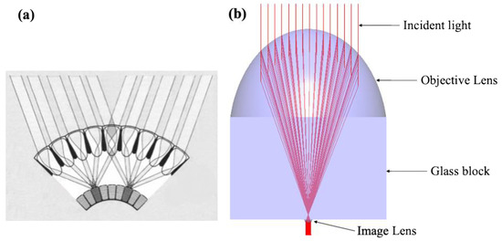
Figure 2.
(a) Scheme showing how the superposition compound eye focuses light onto the retina. (b) Photograph of the light concentrator inspired by the eye of a moth, consisting of two lenses (objective and image lenses) and a glass block, and ray-tracing simulation indicating the parallel wide beam transform to the narrow beam.
In what follows, we start by providing the reader with geometrical optics to optically access this concentrator. In the spirit of the principle of conservation of optical path, the optical path length of all rays traveling through such a concentrator has to be equal. We consider a model consisting of two aspherical lenses that have positive focal lengths ( and ), stitched with a block having a thickness . The radius of the objective and image lenses is and , respectively. On the physical side, the parallel incidence with the beam area is deflected and focused at the F point, followed by spreading to the output parallel beam with a beam area . Hence, the all-optical path is a straight line and intersects at a sole focal point, termed F in Figure 3. The overall concentrator is structured with a homogeneous medium having a uniform refractive index n = 1.49. The expression of the typical optical paths essentially reads:

Figure 3.
A view of lateral cross-section and ray diagram of the dual-lens concentrator unit to collimate and concentrate a parallel beam in the principle of conservation of optical path. Structural parameters of this typical concentrator unit: two aspherical lenses have sizes and focal lengths of , and , respectively, stitched with a block possing a thickness . All components are made of the same material selected here, PMMA with n = 1.49.
Then, the concentration ratio (CR) value simply reads: . Equation (1) is implemented in a Matlab (version Matlab R2019a) routine in such a way that the device complies optical features with the given specifications/parameters: a quadratic equation is solved with a constraint and, of course, a real root was drawn. This way, a xi is found and all co-ordinates of the segment surface in the 2D version are computed along this line. Then, a 3D version of such a dual-lens concentrator, and , was fully obtained by rotating the 2D version along the axis of rotation.
The flowchart, Figure 4, shows the routine that we used to determine the structural design of such a dual-lens concentrator unit satisfying the said optical principle. We started by selecting the appropriate radius of the objective lens of a typical size of 50 mm. The input radius of the image lens (R2) was purposely selected to obtain a given CR value. The other input specifications, refractive index and focal length of the lenses, are specifically selected in a heuristic manner. As is well-known, the large focal length lends the bulky lens, whereas the lens posing a short focal length is essentially difficult to bend the refractive rays at the same point, thus causing the aberrations. So, for a given radius of the lens, we imposed a focal length equal to 1.2 times the radius. A selection of n = 1.49 pertains to the material of choice used to fabricate such a concentrator later, typical of PMMA. By using an ad hoc program written in Matlab to calculate Equation (1), we can then draw the 3D co-ordinates of the surface curve. These co-ordinates, and , were retrieved to model the dual-lens concentrator unit in the LightToolsTM (Version 9.0, Synopsys, Inc., Mountain View, CA, USA) environment for further simulation. The same holds for the other concentrator units with a specific geometrical design. Finally, the primary concentrator was straightforwardly constructed by replicating and translating the identical concentrator unit into a two dimensions array. This process could be repeated to determine an appropriate design for the primary concentrator with different specifications of the concentrator unit. On this basis, an example of the primary concentrator, consisting of 12 dual-lens concentrator units, was modeled in the LightToolsTM (Version 9.0, Synopsys, Inc., Mountain View, CA, USA) environment. A quick ray-tracing of such a primary concentrator was then performed. Figure 5 exhibits that a wide incident beam can be collected and focused into multiple output narrow beams, an implication of minifying the size of the sunbeam and enhancing the CR value. We will elaborate an in-depth discussion of the optical characteristics below with a complete assessment for the aspects, including the size of the focusing area, light distribution, optical efficiency, and concentration ratio.

Figure 4.
Design and analysis flowchart of the superposition compound eye-inspired primary concentrator.
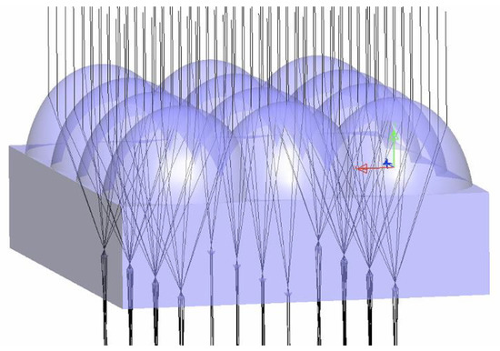
Figure 5.
The structure of the primary concentrator consisting of dual-lens concentrator units and the ray-tracing simulation using LightToolsTM software (Version 9.0, Synopsys, Inc., Mountain View, CA, USA), showing that a wide beam can be collected and focused into multiple narrow areas.
2.2. Secondary Concentrator: Mirror + Reflective Channel
Although the beam size was scaled down in the previous simulation, the approach of using the dual-lens concentrator suffers from certain limits for a thousand CR purpose when it comes to considering both criteria of light performance and cost-related aspects. To attain at a higher CR, the single-concentrator system of this kind has more often required bulky optics, which not only lend a large aberration (resulting in an extended focal spot), but also incurred the unwanted cost of the entire system, as well as not precluding the difficulty in manufacturing. To go further, we here focus on a much easier avenue: a mirror + reflective channel system, aiming to superposition all the concentrated beams to a sole place of interest, called a “secondary concentrator” for the clear reason; this system further contributes to the gain in CR. We are now equipped to implement the coincide of the discrete beam areas to remain in the small concentrating area. We then collect the light at the exit of the secondary concentrator. Coarsely speaking, we still hold the light area with the same dimension as that generated by each dual-lens concentrator unit.
Let us now turn to a specific proposal of the secondary concentrator. As sketched in Figure 6, such a system intrinsically consists mainly of the combination mirror + reflective channel. The reflective channels are rectangular in shape. We assume such components to be laid over a PMMA substrate, because of its commercial availability. A flat mirror would be a plausible selection if we were working on the collimating beam, for instance, redirecting the beam of interest to the given area. For “optically guiding” these beams in the same plane, we could specifically use a channel with nothing in the middle and its edge being a reflective surface, which would be easily implemented with the present thin-film texture technique. Thus, in the rest of this section, we prefer an arrangement of mirror + channel system in a 3D plane where we first rotate the mirrors at the prescribed angles and next couple the redirected beam to the relevant channels. The exit of such a secondary concentrator is the intersection of all channels. Next, we will need angle control of the individual mirror and channel according to the principle detailed below.
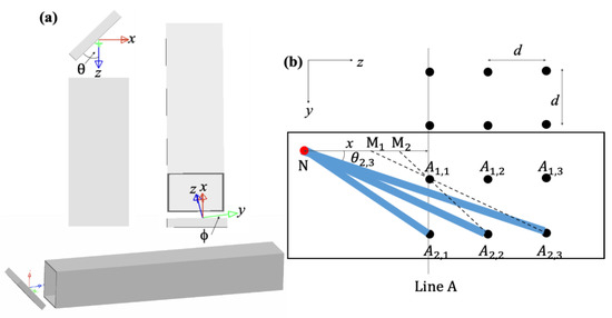
Figure 6.
(a) The arrangement of a pair consisting of mirror and reflective channel. (φ) and (θ) are the angles of the mirror with respect to the vertical (x–y) and transverse (y–z) planes. Note also that to ensure that all redirected beams from mirrors would be parallel to the transverse plane. (b) Design rule of mirror + reflective channel in terms of φ-angle to comply that all beams are guided to a sole area at the exit of the secondary concentrator, N.
The size of the mirror is defined by the very shape of the incidence exited from the dual-lens concentrator unit. The profile of the mirror is then to be totally defined in terms of the angle pair, (φ) and (θ), which is the angle of the mirror with respect to the vertical (x–y) and transverse (y–z) planes (see Figure 6a). For simplicity, all redirected beams would be parallel to the y–z transverse plane. This being said, it appears clearly that the . The channels were settled so that the incidence is normal to their entry port, which simplified the determining of the -angles of the channels (simply kept at ). This brings us to a solution to define the φ-angles for both mirror and channel. Clearly, we can envision that φ-angles must be the same for a pair of mirror + channel, purposing to ensure that the redirected light is guided fully into the channel.
In this illustration, we have tried explicitly an example of mirror + channel structure calculation in such a guiding system, as outlined in Figure 6b, according to what has been discussed in the above sections. The specific model we use has a matrix of 3 × 4 spots, where each spot is representative of a focusing beam collected on the receiver plane. The distance between two adjacent points is d along both axes (Oy and Oz, see Figure 6b). The analogy for the other design of matrix elements among arbitrary m×n points can be pursued on the basis of the following proposed prescription. All mirror + channel pairs are inclined so that the beams then follow the same fate: the beams are directed at a sole area, point N. A logical selection of such a targeted area is at the axis of symmetry of this matrix, which may best serve the purpose of simplification of the calculation later, where the calculation is reduced by half due to the symmetry. Here, the distance between a targeted area (N) and the closest line (Line A) of the assembly of points is an arbitrary x. As for a given arrangement, it is noted also that point N needs to be different from two points M1 and M2 to be sure that the channels cannot be overlapped, which departs from a geometrical intuition as sketched in Figure 6b. So, the reflected light from the rear mirror will not be blocked by the front mirror.
In Figure 6b, we generalize the above concept for an example of a matrix of 3 × 4 points, for instance. The arrangement of the mirrors can be shaped by the respective angle,. The angle of the mirror and channel essentially read:
The calculation providing the angles is for the point set in half of the original matrix. The angles for an upper half are in analogy with the lower half, of course. The basic design uses 12 channel + mirror pairs, but the other design can be devised, and the system shall then behave somewhat similarly. The added complexity of a larger number of points does not change too much the picture of such a secondary concentrator principle. it is confirmed here that the design rules on the arrangement of the mirror and channel are quite clear and tangible, and further verified by a simulation analysis below. All mirrors and channels can be disposed into the large body of a substrate, for instance, a plastic plate. Moreover, it is necessary to say that each beam is subjected to inhomogeneous broadening as it is transported at a long path, stemming from the divergence phenomena. In a sense, the light in the center is miscellaneous of many incidences, which entails the inhomogeneity of the illuminance area. We thus should help to tame this foreseen phenomenon and would give good performances to the CPV system. This demands an apparatus to turn from an inhomogeneous light to a homogenous one.
2.3. Homogenizer: Scattering Box
After the hybridization of the multiple beams at the exit of the secondary concentrator, it is safer to use a homogenizer to serve as a light distributor instead of launching directly such beams to the solar cell. The presence of the hotspot cannot rigorously be treated as an acceptable fashion because, for demand, the inhomogeneous light profile can spoil the solar cell. Rather, an essential uniformity feature needs to be obtained in this stage. It, thus, does matter at the present stage to alter the intensity distribution of the output light from the secondary concentrator. We seek here, along this line, a simple apparatus made up from the reflective plate in tandem, as seen in Figure 7, to skirt the aforementioned issues. Figure 7 sketches a schematic version of the reflective-channel box in a simplified manner. Physically, the inhomogeneous beam can be redistributed as passing through a homogenizer in the following manner: the light beam is furcated into the small channel and redirected at the reflective plate, and probably mixed. Intrinsically, we then can expect a light area with a more uniform distribution, before reaching an MJ solar cell placed at the output side of the homogenizer. We also further characterized a scattering surface for this homogenizer so that the incidence is randomly scattered inside the homogenizer, which facilitates an improvement in the uniformity of the output beam. The surface of such a homogenizer complies with the requirement: the rays are scattered mainly in the forward direction with respect to the incident ray. From the optical viewpoint, the roughness height in the typical range less than (slight rough surface) or comparable to (moderate rough surface) the wavelength of the solar light exhibits strong multiple scattering, most of which is in the forward direction (see Figure 7), and behaves like an equivalent forward scattering surface and is what we seek in this proposal. To geometrically access such texture, we can utilize the nanofabrication technique. A good basis for our proposal is [43], a paper about a nanoporous metal-coated surface using a chemical technique, which is proven to fabricate a large-scale high-reflectivity surface. We intend to give a more complete account elsewhere about the trends in terms of light performance versus texture parameters of the scattering surface. They relate to different and generally more sophisticated aspects of scattering behavior, to specificities of surface texture description, and of numerous well-known scattering theories in such structure, which are not our direct purpose here. We nevertheless anticipate that the potential of such a homogenizer opens vast perspectives, which is worthy to stand as extensive independent research.

Figure 7.
Design of a homogenizer consisting of multi-channels made of scattering surface. Surface roughness effects on light scattering. Surfaces whose roughness is much less than the light wavelength scatter in the specular direction. Rougher surfaces scatter more energy in all directions, including the direction back to the incidence light.
3. Simulation Result
To guide us in the design of the CPV system, the LightToolsTM (Version 9.0, Synopsys, Inc., Mountain View, CA, USA) simulation is implemented to examine in this section how the light is transformed (shape, uniformity, and intensity) in the proposed CPV system. Using the above-developed model, we now assess and analyze the CR value, optical efficiency, intensity distribution, and acceptance angle. We perform ray-tracing and light performance of the typical design shown in Figure 1. The aim of the simulation is to obtain the high CR value targeting greater than 1000 sun and flux distribution as uniform as possible on the receiver plane of the solar cell. One obvious consequence when targeting an HCPV system is to lower the acceptance angle, which we are also going to detail below. In this simulation, the number of rays was taken to be fairly large (up to 10 million rays), allowing a reliable test. We adopt the ray picture (Figure 8) to help the reader to grasp a complete view of the optical principle of such an entire CPV system, such as that of Figure 1. Table 1 gathers all the design parameters for our proposed CPV system. A primary concentrator made up of a certain number of dual-lens concentrator units (we here choose 12 units) will collect a wide incident beam and focus on multiple areas. We will gauge the convergence feature of such a concentrator unit by varying the radius of the image lens from 2.5 to 10 mm and fixing that of the objective lens at 50 mm. The number of mirror + channel pairs, of course, is also 12 to treat a respective number of focusing beams exiting from the primary concentrator. These parameters in Table are selected for simulation and optimization purposes. The size of the objective lenses in the primary concentrator is similar to a commercial Fresnel lens, which are used in some studies on a super high CPV system [44].
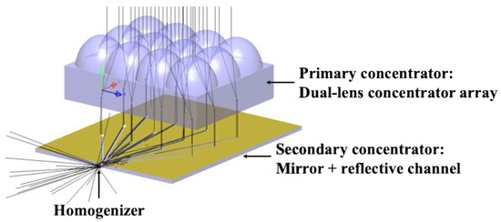
Figure 8.
Ray-tracing analysis of the proposed HCPV system using LightToolsTM software (Version 9.0, Synopsys, Inc., Mountain View, CA, USA), indicating that a wide incident beam concentrated through the primary concentrator, guided through the secondary concentrator, and redistributed through the homogenizer.

Table 1.
The specifications of our proposed HCPV system.
3.1. The Light Characteristics of Primary Concentrator
The first step in finely understanding the possibility of minifying the sunray now obviously leads to exploring the light characteristic of the dual-lens concentrator. An optical simulation was implemented to judge the proposed concentrator over a regular PMMA surface, modeled and based on the reasonable optical characteristics. While light passes through the regular optical component, its intensity does not preclude to the subject of the loss concerning the Fresnel loss. In most of the following simulations, we shall impose that the Fresnel loss is introduced for all interfaces of this concentrator.
At this stage, before proceeding, a further precaution regards the chromatic dispersion feature, which is considered an inherent characteristic of refractive optics depending on material properties in refractive devices. In practice, it is well-known that the material dispersion nature results in the expansion of the beam as passing through the optical components. With this in mind, the usual way to find the said effect makes use of a comparative study for the dual-lens concentrator illuminated under either a monochromatic source or solar spectrum source. Using a model constructed in LightToolsTM (Version 9.0, Synopsys, Inc., Mountain View, CA, USA) optical simulations, the light performance is calculated initially for a green wavelength source, λ = 550 nm. In parallel, the broad-spectrum light source is taken as a solar spectrum with wavelengths characteristically fitted at the range of 300–1500 nm. We here position a solar source on top of the concentrator, shining light at a normal incidence angle. We then launch the light distribution in each configuration at the respective receiver plane. We would analyze light areas located at various distances within the range of a few centimeters away from the posterior lens.
We start with a given R1/R2 pair of radius ratios of 50/10, where R1 is radius of objective lens and R2 is radius of image lens. At such a value, we will initially clarify the role of dispersion in optical features and the possibility of minifying the beam size using this concentrator. The simulation is implemented for either a solar spectrum or monochromatic light source with five selected distances at an interval of 1 cm. Needless to say, the incidence from the simulated source has to fall fully within the aperture of the objective lens for a fair assessment. To hold generality for our study, a square-like source possessing a side length of (~70 mm) is a logical selection. In Figure 9a,b, we give the simulated light profiles at two selected distances, 1 vs. 5 cm, respectively, for a monochromatic source, the green wavelength of 550 nm. In Figure 9c,d, we report the light distribution obtained on the receiver plane at two positions as above with reconstructing a solar spectrum as an irradiation source. Without any surprises, as irradiated with the monochromatic source, the output beam size remains fairly constant at an indicated range of less than 5 cm. This indicates that such a proposed concentrator creates the output beam that is able to show up as a collimating one but with a sizably smaller size compared to the input beam. In another scenario, using a light source mimicking the solar spectrum, we investigate the spatial change in the output beam across the transmission direction. For this purpose, we expect a simulation assessment close to the real condition. In this latter version of a particular form of dispersion, the beam is unfortunately broadened along its transmission direction, because the sunbeams have inevitable chromatic dispersion as transmitting a material medium. To help the reader to grasp a complete view, we gather in Figure 9e the beam size with respect to distance. Simulations plainly confirm an enlarged divergence beam at an increased distance, consistently with the optical viewpoint. As seen here, when taking into account the dispersion behavior, the beam is expanded about 1.5 times comparing between two distances, 1 vs. 5 cm. The divergence angle is deduced from a mathematic tool available in LightTools (Version 9.0, Synopsys, Inc., Mountain View, CA, USA), about . This fact compels the careful design to grant the optical functionality desired; specifically, here, this is the beam size of interest. This remark opportunely provides us an option: we should next consider proposing the secondary concentrator system below, with the adequate close distance and design, a proper input/output geometry of the secondary concentrator to mitigate the divergence phenomena.
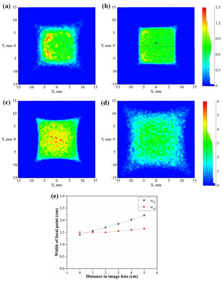
Figure 9.
Light distribution on the receiver plane using monochromatic source (λ = 550 nm) at a distance away from the image lens: (a) 1 cm; (b) 5 cm. Light distribution on the receiver plane using solar light source at a distance away from the image lens: (c) 1 cm; (d) 5 cm. (e) Graph summarizes the relation between distance to image lens and with of focal point in both cases: monochromatic and solar light source.
To go further, playing with this model with all the above characteristics in mind, we can now proceed with the optimization process through varying structure parameters. With the design principle of the concentrator presented here, and, if the possibility of manufacturing is considered, the expected CR could probably be further increased. We remind again that the interest in CR value is to be more than 1000×. On the optical side, the obtained CR is essentially dictated by the radius ratio of two lenses. In a sensible manner, either the objective lens is increased or the image lens is decreased along this avenue. Shrinking the radius of the posterior lens is a simple way to further minify the size of the output beam. As a next step, we keep the radius of the anterior lens but varying R2. The other investigated R2 are 5 and 2.5 mm (see Figure 10a). We again exploited LightToolsTM (Version 9.0, Synopsys, Inc., Mountain View, CA, USA) simulations to assess the light profile at the exit of these designed concentrators. In Figure 10b–d, we, therefore, perform the same exercise as in Figure 9, but for the fixed distance, so, say, 1 cm. In essence, the optical phenomena are conserved, except the size of the output beam is dissimilar. Specifically, to illustrate this, Figure 10b–d compare the light profile of the aforementioned designs of the concentrator in the target of collimating and scaling down the output beam with various R2. We see from the obtained results, intuitively, in a coarser sensing, when decreasing the R2, the corresponding size of the output beam is minified. Unsurprisingly, in these investigated designs, the concentrator possessing the smallest radius of the image lens, R2 = 2.5 mm, yields the narrowest width of the concentrated area (4 vs. 8 for R2 = 5 mm vs. 15 for R2 = 10 mm). This is a first good sign that the concentrating devices investigated here lend themselves to provide a narrow collimated beam. For the sake of clarity, we thus look preferably for the possible use of the flat mirror so as to redirect the collimating beam. This is unlike the issue of the non-collimating beam addressed in the present two-concentrator HCPV design, which has often required curved mirrors in the secondary concentrator. For technological simplicity, such a flat mirror remains, by far, the preferred choice over the curved optics, ensuring long light transportation with low loss penalty, but also mitigation of imperfection and alignment error during the manufacturing and operation processes. We envision that the design of R2 = 2.5 mm will preferably be elaborated as a concept of principle regarding the fabrication issue within our lab’s capabilities and that its basis could rest on a transparent material, such as PMMA. The CR here is determined to be ~300× in the best configuration, while the optical efficiency at this stage is 92%, also from LightToolsTM (Version 9.0, Synopsys, Inc., Mountain View, CA, USA). Therefore, it is confirmed here that the design of choice involves R1 = 50 mm, R2 = 2.5 mm, f1 = 62.5 mm, f2 = 3.125 mm, and T = 65.625 mm.

Figure 10.
(a) Pictures of the proposed dual-lens concentrator unit with different radius of the image lens, R2 = 2.5; 5; 10 mm, and a fixed radius of the objective lens R1 = 50 mm. Light distribution on the receiver away from the image lens with a distance of 1 cm for the dual-lens concentrator unit having R2 of (b) 2.5 mm, (c) 5 mm, and (d) 10 mm.
It is, thus, clear that our concentrator design exhibits a hundred times improvement in the concentrating ratio, at least. Such a model has shown the efficient optical characteristics that we seek in this work; the CR is nevertheless less than our initial target (let us again insist that our goal is a CR of roughly 1000×). One emerging possibility toward this target is to accumulate many discrete beams into a sole area, aiming to further increase the ultimate CR. As can be intuitive, if the size of the input beam is larger proportional to the amount of the concentrator unit, while the output is exactly the same as that of a single concentrator, this will entail a sizable enhanced CR. To expand the input beam, the concentrator unit is juxtaposed in linear arrays. We here selected a primary concentrator configuration consisting of 12 dual-lens concentrator units. As confirmed logically from the simulation, see Figure 11, a batch of the individual equidistant focus points generated on the receiver plane is a good starting point for accumulating them into a sole area. As said earlier, the caveat that can be seen here is that the divergence of the beam will be a penalty for the long propagation of light. We will mitigate this effect by putting the secondary concentrator system, described below, at an adequate close distance to the primary concentrator: we will stick the secondary system at a distance of 1cm, akin to the distance at which the beam is not expanded negligibly. Our next step is, therefore, to shape the “optical access” for such a secondary concentrator in order to target a CR > 1000×.
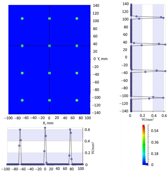
Figure 11.
An array of such dual-lens concentrator units forms a set of equidistant focusing points, provisionally fulfilling the target of a primary concentrator at this stage.
3.2. The Light Characteristics of the Secondary Concentrator
Our purpose is now to transmit and combine the light spots exited from the primary collimator in order to excite the photo-electron process in the solar cell. We, here, recourse the buildup mechanism for the multi-beam generated from the primary concentrator, see Figure 11, to implement this idea. In a specific example, we deal here with how to accumulate a matrix of 3 × 4 spots, as presented in Figure 11. Indeed, this could be accomplished by feeding the 12 flat mirrors, followed by a similar number of reflective channels located nearby to minimize the optical loss elsewhere on the path. To give a more precise visualization, we present the design of such a secondary concentrator, in a pictorial view, as a series of a pair of mirrors and channels (see Figure 12a). We check the relevance of the aforementioned design philosophy, Section 2.2, in deterministically providing the arrangement of the mirror + channel in a particular case. This way, a design of mirror + channel is implemented and a reflectivity of 98% is imposed, which can allow increasing of CR in the thousands. A high reflectance of about 98%, as we assume, should be easily achievable with the technologically mature mirror plating [39]. Along this line, we show in Figure 12a the layout of a device consisting of a flat mirror (here, θ-angle is fixed at ) tilted intentionally with a precalculated φ-angle in accordance with the discussion in Section 2.2. We specifically use a flat mirror, with edges defined by the very shape of the incidence, an array of reflective mirrors of typical size 4 × 4 × 0.5 mm and a distance from center to center of d = 70 mm, equivalent to the distance of two successive image lenses. The default dimension of the guiding hollow channels is 4 × 4 mm, with a length depending on the position of the light spot in the matrix, allowing light to bounce and transmit inside the channel. The channels are carved on the same substrate of the secondary concentrator and their branches intersect at an exit of the secondary concentrator. All in all, in this model, the guided light beams are eventually delivered to the sole exit of the secondary concentrator, which merges optically all light beams within this area of interest. For the receiver area located at this exit, we assume a size such as the 6 × 9 mm multi-junction solar cell array, and, therefore, a light distribution spanned to an area of 6 × 9 mm is taken into consideration. Being narrow, this design amounts to remaining the relatively small size of the output beam, allowing high CR to be attained as expected. Based on a comparison of the size of the input and output beams, we bracket concentration ratio figures of merit of such an HCPV system to be 1088×.
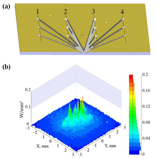
Figure 12.
(a) Design of the secondary concentrator is comprised of 12 pairs of mirror + reflective channel, aiming to guide all beams to a sole area at the exit. (b) Light distribution at the exit of the secondary concentrator indicates an inhomogeneous illumination area as a consequence of divergence phenomena.
Figure 12b presents the light profile obtained at the exit of the secondary concentrator, constrained by a size of 6 × 9 mm. The result can be seen in the form of a color map of the outgoing flux in the exit gate. As the light beams enter this concentrator, the superposition form at the intersection of the discrete branches is constituted. At the exit gate of this apparatus, these beam profiles tend to merge and form a sole focusing area of sunlight. A splendid achievement in this respect is a calculated CR value of 1088×. Here, the light intensity is somewhat lost, which is a price to pay to trade off a CR gain. Specifically, the optical efficiency is calculated in this stage, η = 83.4%, from LightTools (Version 9.0, Synopsys, Inc., Mountain View, CA, USA). The optical loss is thought to stem from two major reasons: (i) the dip stemming from reflection loss at the reflective surfaces: mirrors and channels; and (ii) the divergence of the beam traveling in a long-distance can cause attenuation of light. However, in essence, the optical loss is in an acceptable range and compares well to the other studies [34,35]. Moreover, our design philosophy can be intuitive to attain a higher CR value in principle by simply adding up some single-concentrator units into the primary concentrator.
The last aspect that we can view on this color map of light distribution is the uniformity extent of the output light. Instead of having a homogeneous illumination area, the distribution splits into several somewhat certain areas (Figure 12b), accounting for the imperfection of the illumination area, which fundamentally jeopardizes the solar cell. We attribute this to the unavoidable divergence of the light beam arising in the long transportation. Admittedly, the obtainment of uniformity of light at the exit guiding is a theoretical difficulty still, and, for this reason, we will later address a light-distributor-coupled design in the next paragraph.
3.3. The Light Characteristics of the Homogenizer
In addition to the high concentration and optical efficiency, characterization of uniform light distribution of the focal area is of high interest in the field of concentrating photovoltaic as a prerequisite requirement purposely aiming to a stable operation condition below the danger of known failure in relation to overheating issues. Being, in principle, an optical concept, a uniform solar source passing a two-lens system separated by the sum of their two focal lengths, we should obtain a perfect uniformity. However, remember that the unwanted dispersion is taken into consideration in the previous analysis and that imperfections of the illumination area at the exit of the secondary concentrator then appear in a not so trivial fashion. As a result, we observe that there is some hotspot in the illumination area of interest. Because of the illumination inhomogeneity, there is a major interest in designing efficient light distributors reaching high uniformity at the illumination area of interest. The light distributor, sometimes called homogenizer, is fueled by an effort to redistribute this illumination area. The homogenizer is a workhorse of the CPV system, which can make the hotspot faint to a certain extent. Much achievement in this kind of homogenizer was well-documented on the basis of either reflection [2,45] or refraction [46,47]. Relying on reflections, rather than the refraction counterpart, seems a better option, which brings a lot of advantages [2]. We will see how the inhomogeneous area can be positively amended with the aid of a homogenizer, which is a specific issue we address/settle in the below section.
Given this state of matter, we will discuss below the role of these “light distributors” in the simulation. The particular aspects that we propose to use essentially furcate and blend the nonuniform light beam inside such a distributor. To this end, they involve a design possessing two features: a box with well-defined mini-channels and the whole surface is high scattering/reflection. The corresponding optical phenomena fall in the category coined in our recent study [2]. We emphasize that a combination of both the above features is needed to grant a uniform beam to deploy for the design philosophy of homogenizers. The first feature is a box consisting of a multichannel, which is analogous to a design that we recently identified under the term of a crustacean-eye-like homogenizer, which intuitively suggests to branch the inhomogeneous beam. One may then expect that such subdivision may cancel the hotspot and affect its light distribution; hence, the uniformity of light area can be positively improved. The second feature, somewhat more challenging, is the main core difference/disparity to the other developed homogenizer in relation to the fabrication technique of a scattering surface. We furthered this design by proposing a scattering surface for such a homogenizer. The core of this effect is the ability of random redirection of light at each edge. This case is known as the forward scattering in optics, and is much used in imaging techniques [48] and Raman scattering [49]. For an efficient redistribution, the incoming light is scattered at different angles depending on the textured surface, and thus logically flatting the hotspot. We believe that the combination of both features can be exploited to produce a uniform light as expected. We will prove these concepts by a simulation study later.
We opt for a scattering-channel box with vertical sidewalls to obtain the uniform situation, and, of course, still high optical efficiency. With reference to (illustration of) Figure 13, we will examine the light distribution possibility with three types of design, and start by the multi-channel reflective box and conventional scattering box, that of Figure 13a,b, respectively, before going to an integrated fashion, i.e., a multi-channel scattering box, that of Figure 13c. With this idea in mind, let us assess the uniformity and optical efficiency (Figure 14) of the illumination area at the exit of these homogenizers. To reach the desired performance and the possibility of manufacturing, we choose a parameter design at: the size of the input side 6 × 9 mm; length L = 6 mm; thickness of side-edge T = 0.1 mm; a number of channels = 4. The shape of such homogenizers is kept the same, which would give fair insurance that the number of the scattering/reflection events, insofar as is fairly identical.

Figure 13.
Design of three types of homogenizer: (a) multi-channel reflective box, (b) conventional scattering box, and (c) integrated version termed multi-channel scattering box.
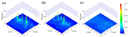
Figure 14.
Light distribution on the receiver using three types of homogenizer: (a) multi-channel reflective box, (b) conventional scattering box, and (c) integrated version termed multi-channel scattering box.
Let us first consider the multi-channel reflective box, as depicted in Figure 14a. The design we explore is that of Figure 13a, a reflective box with a thick side-wall of 0.1 mm. It consists of four channels with surfaces that fully resemble the side-wall. In essence, no patterning is made on these surfaces and they are merely reflective surfaces. In spite of its technological simplicity, using this design, the light would not be clearly redistributed (see Figure 14a). This can be pictured as follows: the inhomogeneous beam at the exit of the guiding system is essentially the assembly of parallel beams. In spite of branching into a small area, such a sub-beam is normally reflected at the mirror surface, then merges at the exit of the homogenizer. So, this only leads to the fact that the hotspot is just moved away from each other and still appears at the area of interest. This result prompted us to further investigate a new kind of homogenizer on the basis of the scattering concept.
As for the reason for the simultaneous influence of a design of the multi-channel box, a sensible comparison can be made here with two models: multi-channel and conventional boxes whose plates are scattering surfaces, pictured in Figure 13b,c. We try in the following to verify the role of the scattering surface in the modulation of light inside the homogenizer. To illustrate this, Figure 14b,c compare the light distribution of such two models. For the simple box, the distribution effect of light is featureless, in which the hotspot is free from cancellation. On the contrary, as the conventional box is divided into mini-channels, i.e., typical four channels, we obtain a clear improvement over the uniformity of light area compared to the other investigated models. Such an integrated structure apparently tends to produce a uniform distribution of light as expected. The main ingredient for our discrepancy is the fact that, in essence, the conventional box only affected the outermost beams (on lines 1 and 4, pictured in Figure 12a), whereas the beams from the spot on the middle lines (2 vs. 3) may pass through the homogenizer without any interaction to the scattering plates. This can be solved if we make use of the multichannel box because the scattering events occurring at the plates are likely much more visited, as can be intuitive, especially to the central beams from lines 2 and 3. We also revisit the optical efficiency at the illumination area at the exit of the integrated homogenizer. For a given reflectivity, this lowers the optical efficiency depending on how the scattering event takes place. Its loss can be optimally low thanks to the present silver coating, 95%; thus, this minor loss from the “high scattering surface” philosophy underlying the proposal [43] is still benign. In fact, the optical efficiency was quantitatively determined at this stage to be about 75%, which is grossly valid and what we expect here. The main optical loss comes from Fresnel loss at the surfaces and dispersion in the primary concentrator part. In this design, the loss in the secondary concentrator is minimized because the light is confined tightly inside the reflective channel.
Experimentally, this design can be completely accomplished through laboratory-based techniques to form artificially generated rough surfaces. Simulation logically confirms a reduced efficiency penalty for a CPV system with an inserted homogenizer; however, uniformity is restored in relative terms. Implementation of multiple channels + scattering surfaces is a successful example of how uniformity is improved. Overall, fairly good light performance is observed in this basic design, while, for the distribution of light in the area of interest, there is no hotspot. Obviously, at this stage, the interplay of light modulation with the very essential ingredients (length, width, and number of channels) of the homogenizer may affect/fine-tune the details of the result. We did not attempt to improve further the uniformity as, if its refinement is implemented, that would, however, introduce complexities that we do not need for our central claims. As seen here, the preliminary design proposed in this work suffices to cancel the inhomogeneity of the illumination area. In this work, we do not explore the full parametric study that would impact somehow, for instance, the light performance and tolerance, as this obviously depends on the configuration of the homogenizer. However, the impact of structural parameters of the homogenizer on the light distribution would be needed for more firm physical conclusions. We believe that the more important point is to expose an embodiment strategy for the “multi-channel + random reflection” principle to deploy for the homogenizer, contributing to the current ongoing efforts in the homogenizer design. This design somewhat relaxes the hotspot, provisionally fulfilling the target of a light distributor. Such a high uniformity of the light of interest results in much less heat sink and much more power conversion efficiency for a CPV system, which is an important point in realistic applications.
4. Discussion
However, remember that the simulations are made in the ideal condition, and that small errors are then penetrated during the operation process. These errors can be understood in relation to sun-tracking inaccuracy, which is detrimental to the attainable optical efficiency of the entire CPV system. We even believe that it is essential to deal with such imperfections because they would also occur in practice. We, here, attempted to draw the foreseen loss to select a proper sun-tracking system. It is, thus, useful to check that the present implementation with well-defined tolerances does work well for a CPV system. Specifically, the normal incidence is taken as a reference to the CPV system at the ideal operation. To investigate the angular tolerance of the optical efficiency features, we scan the tilt of the source by steps from to . We set the structural parameters for the entire CPV system at the best value found above. As indicated in Figure 15, we typically obtain ≈90% at an incidence angle of . Targeting a high CR value, it is certain that the price of a low acceptance angle is paid; therefore, a high-accuracy sun-tracking system is often required. This means, for the time being, the accuracy of sun-tracking is less than 0.6 degrees, which we are aware that such devices have been produced for the CPV industry.
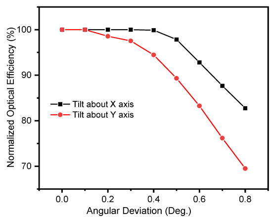
Figure 15.
Normalized optical efficiencies of our proposed HCPV system under various incidence angles along x-axis and y-axis.
To show this ability for our design, we manufacture a dual-lens concentrator unit and observe how light at the output is affected. The fabrication of the device is implemented, and experimental results for light coupling are tested. The man-made dual-lens concentrator unit was manufactured by the computerized numerical control (CNC) molding method. The typical procedure is as follows: a 3D model was drawn in the AutoCAD environment around the best design determined from the simulation data. The 3D drawing was then converted to G-code output of the Aspire software to communicate with the CNC machine. The molding stage was then processed to render a flat PMMA plate to a concentrator unit. The radius of the as-fabricated lenses was 50 and 2.5 mm, respectively, whereas the thickness of the glass block was 62,625 mm. The resolution of the CNC machine used in this work is 20 μm. The polishing process was finally implemented to prevent the surface imperfections that may be caused in the molding stage, which can induce the attenuation of the collection efficiency of such a concentrator unit.
To continue this section, we report on the essential optical characteristics for experimental proof of the fabricated dual-lens concentrator, as shown in Figure 16a–c. Specifically, for an optical test, the as-prepared concentrator unit was irradiated under a collimating red laser (Model: 6500-0559-11), λ = 632.8 nm. The output beam is captured at the distance of 1 cm. Intuitively, we observe that the concentrator unit can create the focusing spot on the screen (see Figure 16d). It is elementary to conclude that a mm-sized focal area is convincingly achieved in this configuration. It is admittedly difficult to attain a perfect illumination area at a further distance as in the simulation, and this is what is, in fact, observed. The substantial difference observed here can be attributed, for a heuristic reason, to the limit of our CNC resolution to design the sophisticated optics of the dual-lens concentrator of this kind (nonoptimized design). Again, we do not provide more data because design work still has to be conducted to fine-tune the device. The absence of such data for reported optical proof prompt us to postpone this in further publications. We anticipate that the design refinements should help to tame this unforeseen phenomenon and would give better performances to the proposed solar concentrator; for example, we may impose diamond tuning or high-resolution CNC. In addition, to be competitive, the primary concentrator (lens array) and secondary concentrator must be fabricated using a low-cost process. According to this goal, they must be manufactured using plastic material. The advantage of using plastic to fabricate the M-CPC is the capacity to mold the system, which is a low-cost solution for mass production. Fortunately, simplicity in those structures support the molding fabrication method; therefore, we hope that a full system made by molding method will be implemented and tested in the next study.
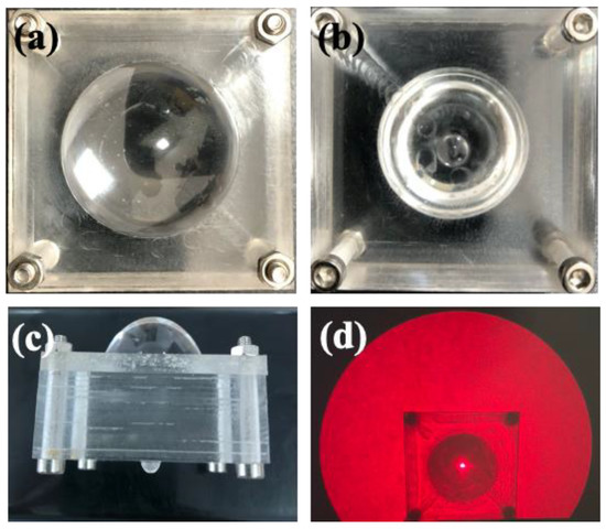
Figure 16.
Photographs of the dual-lens concentrator unit from (a) objective lens side, (b) image lens side, (c) side-view of the dual-lens concentrator, (d) a focusing point in a mm-sized area using such concentrator under laser irradiation.
5. Conclusions
We have proposed a generic approach for an HCPV system, starting from primary dual-lens concentrator consideration and going to secondary concentrator implementation based on mirror + reflective channel and redistribution of the light in a mini-channel box having the scattering surface. The basic design of the concentrator unit uses two positive lenses pieced by a glass block, able to collect sunlight in the form of a nearly collimating beam, and, in parallel, minify the beam size, in which the concentration ratio is proportional to the radius ratio of two used positive lenses. To go further in CR gain, the shape of optics consisting of an array of concentrator units can then be exploited. The secondary concentrator was located beneath the primary concentrator, and consists of a mirror + hollow channel for reflecting and superimposing light purposes. We illustrated the operation of the two-concentrator system in an optical simulation. We have found a CR value of around 1088x for this first design attempt, but other larger designs can be devised, and the device shall then behave somewhat similar. The overall optical efficiency of the full system is 75%, which might seem high, known from the HCPV viewpoint. Moreover, the inhomogeneity of the superimposed illumination area is circumvented by the design of the homogenizer. We have proposed an avenue to exploit the homogenizer on account of the random scattering principle. We obtained uniform distribution of illumination area, in particular, making the MJ cell functional and immune/averse to overheating to some extent. We also hope that such a design could find some echoes in the ongoing efforts in the present CPV community.
Author Contributions
Original idea conceptualization, N.H.V.; Simulation, D.T.V., H.V., T.Q.T., T.P.N. and N.H.V.; formal analysis, N.H.V.; experiment, N.M.K. and D.T.V.; writing—original draft preparation, D.T.V.; review and editing, N.H.V. and S.S.; project administration, S.S and N.H.V. All authors have read and agreed to the published version of the manuscript.
Funding
This work was supported by the National Research Foundation of Korea (NRF) grant funded by the Korea government (MSIT) (No. 2021R1A2C1010879). This work was also supported by Vietnam National Foundation for Science and Technology Development (NAFOSTED) under grant number NCUD.01-2019.13.
Institutional Review Board Statement
Not applicable.
Informed Consent Statement
Not applicable.
Data Availability Statement
The data that support the findings of this study are available on request from the first author.
Acknowledgments
The authors gratefully acknowledge Phenikaa University and Vietnam National Foundation for Science and Technology Development.
Conflicts of Interest
The authors declare no conflict of interest.
References
- Algora, C.; Espinet-Gonzalez, P.; Vázquez, M.; Bosco, N.; Miller, D.; Kurtz, S.; Rubio, F.; McConnell, R. Reliability. In Handbook of Concentrator Photovoltaic Technolology; Wiley: Hoboken, NJ, USA, 2016; pp. 521–588. [Google Scholar]
- Vu, D.T.; Vu, H.; Vu, N.H. A homogeniser inspired by the crustacean’s eye with uniform irradiance distribution and high optical efficiency characteristics for concentrated photovoltaics system. Sol. Energy 2021, 221, 87–98. [Google Scholar] [CrossRef]
- Shanks, K.; Senthilarasu, S.; Mallick, T.K. Optics for concentrating photovoltaics: Trends, limits and opportunities for materials and design. Renew. Sustain. Energy Rev. 2016, 60, 394–407. [Google Scholar] [CrossRef] [Green Version]
- Sattar, A.; Farooq, M.; Amjad, M.; Saeed, M.A.; Nawaz, S.; Mujtaba, M.A.; Anwar, S.; El-Sherbeeny, A.M.; Soudagar, M.E.M.; Filho, E.P.B.; et al. Performance evaluation of a direct absorption collector for solar thermal energy conversion. Energies 2020, 13, 4956. [Google Scholar] [CrossRef]
- Khamooshi, M.; Salati, H.; Egelioglu, F.; Faghiri, A.H.; Tarabishi, J.; Babadi, S. A review of solar photovoltaic concentrators. Int. J. Photoenergy 2014, 2014, 3856. [Google Scholar] [CrossRef]
- Wiesenfarth, M.; Anton, I.; Bett, A.W. Challenges in the design of concentrator photovoltaic (CPV) modules to achieve highest efficiencies. Appl. Phys. Rev. 2018, 5, 041601. [Google Scholar] [CrossRef] [Green Version]
- El Himer, S.; El Ayane, S.; El Yahyaoui, S.; Salvestrini, J.P.; Ahaitouf, A. Photovoltaic Concentration: Research and Development. Energies 2020, 13, 5721. [Google Scholar] [CrossRef]
- Wen, X.; Chen, C.; Lu, S.; Li, K.; Kondrotas, R.; Zhao, Y.; Chen, W.; Gao, L.; Wang, C.; Zhang, J.; et al. Vapor transport deposition of antimony selenide thin film solar cells with 7.6% efficiency. Nat. Commun. 2018, 9, 2179. [Google Scholar] [CrossRef]
- Tang, R.; Wang, X.; Lian, W.; Huang, J.; Wei, Q.; Huang, M.; Yin, Y.; Jiang, C.; Yang, S.; Xing, G.; et al. Hydrothermal deposition of antimony selenosulfide thin films enables solar cells with 10% efficiency. Nat. Energy 2020, 5, 587–595. [Google Scholar] [CrossRef]
- McMeekin, D.P.; Mahesh, S.; Noel, N.K.; Klug, M.T.; Lim, J.; Warby, J.H.; Ball, J.M.; Herz, L.M.; Johnston, M.B.; Snaith, H.J. Solution-Processed All-Perovskite Multi-junction Solar Cells. Joule 2019, 3, 387–401. [Google Scholar] [CrossRef] [Green Version]
- Barrutia, L.; Lombardero, I.; Ochoa, M.; Gabás, M.; García, I.; Palacios, T.; Johnson, A.; Rey-Stolle, I.; Algora, C. On the use of graphene to improve the performance of concentrator III-V multijunction solar cells. Prog. Photovolt. Res. Appl. 2020, 28, 60–70. [Google Scholar] [CrossRef]
- Saeed, M.A.; Cheng, S.; Biswas, S.; Kim, S.H.; Kwon, S.-K.; Kim, H.; Kim, Y.-H.; Shim, J.W. Remarkably high performance of organic photovoltaic devices with 3,9-bis(2-methylene-(3-(1,1-dicyanomethylene)-indanone))-5,5,11,11-tetrakis(4-hexyl meta-phenyl)-dithieno[2,3-d:2′,3′-d’]-s-indaceno[1,2-b:5,6-b’]dithiophene)-ethylhexyloxy] photoactive acceptor under halogen light illumination. J. Power Sources 2022, 518, 230782. [Google Scholar]
- Saeed, M.A.; Kim, S.H.; Kim, H.; Liang, J.; Woo, H.Y.; Kim, T.G.; Yan, H.; Shim, J.W. Indoor Organic Photovoltaics: Optimal Cell Design Principles with Synergistic Parasitic Resistance and Optical Modulation Effect. Adv. Energy Mater. 2021, 11, 2003103. [Google Scholar] [CrossRef]
- Bouich, A.; Marí-Guaita, J.; Sahraoui, B.; Palacios, P.; Marí, B. Tetrabutylammonium (TBA)-Doped Methylammonium Lead Iodide: High Quality and Stable Perovskite Thin Films. Front. Energy Res. 2022, 10, 840817. [Google Scholar] [CrossRef]
- Bouich, A.; Marí-Guaita, J.; Bouich, A.; Pradas, I.G.; Marí, B. Towards Manufacture Stable Lead Perovskite APbI3 (A = Cs, MA, FA) Based Solar Cells with Low-Cost Techniques. Eng. Proc. 2022, 3, 81. [Google Scholar]
- Geisz, J.F.; France, R.M.; Schulte, K.L.; Steiner, M.A.; Norman, A.G.; Guthrey, H.L.; Young, M.R.; Song, T.; Moriarty, T. Six-junction III–V solar cells with 47.1% conversion efficiency under 143 Suns concentration. Nat. Energy 2020, 5, 326–335. [Google Scholar] [CrossRef]
- Pérez-Higueras, P.; Muñoz, E.; Almonacid, G.; Vidal, P.G. High Concentrator PhotoVoltaics efficiencies: Present status and forecast. Renew. Sustain. Energy Rev. 2011, 15, 1810–1815. [Google Scholar] [CrossRef]
- Theristis, M.; O’Donovan, T.S. Electrical-thermal analysis of III–V triple-junction solar cells under variable spectra and ambient temperatures. Sol. Energy 2015, 118, 533–546. [Google Scholar] [CrossRef] [Green Version]
- Vu, D.T.; Vu, H.; Shin, S.; Tien, T.Q.; Vu, N.H. New mechanism of a daylighting system using optical-fiber-less design for illumination in multi-storey building. Sol. Energy 2021, 225, 412–426. [Google Scholar] [CrossRef]
- Shanks, K.; Baig, H.; Singh, N.P.; Senthilarasu, S.; Reddy, K.S.; Mallick, T.K. Prototype fabrication and experimental investigation of a conjugate refractive reflective homogeniser in a cassegrain concentrator. Sol. Energy 2017, 142, 97–108. [Google Scholar] [CrossRef]
- Felsberger, R.; Buchroithner, A.; Gerl, B.; Schweighofer, B.; Wegleiter, H. Design and testing of concentrated photovoltaic arrays for retrofitting of solar thermal parabolic trough collectors. Appl. Energy 2021, 300, 117427. [Google Scholar] [CrossRef]
- Singh, P.L.; Ganesan, S.; Yàdav, G.C. Technical note: Performance study of a linear Fresnel concentrating solar device. Renew. Energy 1999, 18, 409–416. [Google Scholar] [CrossRef]
- Wu, Y.; Eames, P.; Mallick, T.; Sabry, M. Experimental characterisation of a Fresnel lens photovoltaic concentrating system. Sol. Energy 2012, 86, 430–440. [Google Scholar] [CrossRef] [Green Version]
- Nelson, D.T.; Evans, D.L.; Bansal, R.K. Linear Fresnel lens concentrators. Sol. Energy 1975, 17, 285–289. [Google Scholar] [CrossRef]
- Jorgensen, G.; Wendelin, T. Uniform Flux Dish Concentrators for Photovoltaic Application. In Proceedings of the National Solar Energy Conference, Cocoa Beach, FL, USA, 13–18 June 1992. [Google Scholar]
- Leutz, R.; Suzuki, A.; Akisawa, A.; Kashiwagi, T. Design of a Nonimaging Fresnel Lens for Solar Concentrators. In Proceedings of the ISES Solar World Congress, Taejon, Korea, 24–29 August 1997; Elsevier: Amsterdam, The Netherlands, 1999; Volume 65, pp. 379–387. [Google Scholar]
- Hastings, L.J.; Allums, S.L. Performance Characteristics of a 1.8 × 3.7 m in Fresnel Lens Solar Concentrator. Sci. Putljcations A 1979, 3, 62410. [Google Scholar] [CrossRef]
- Akisawa, A.; Hiramatsu, M.; Ozaki, K. Design of Dome-Shaped Non-Imaging Fresnel Lenses Taking Chromatic Aberration into Account. Sol. Energy 2012, 86, 877–885. [Google Scholar] [CrossRef]
- Pham, T.T.; Vu, N.H.; Shin, S. Novel Design of Primary Optical Elements Based on a Linear Fresnel Lens for Concentrator Photovoltaic Technology. Energies 2019, 12, 1209. [Google Scholar] [CrossRef] [Green Version]
- Canavarro, D.; Chaves, J.; Collares-Pereira, M. New second-stage concentrators (XX SMS) for parabolic primaries; Comparison with conventional parabolic trough concentrators. Sol. Energy 2013, 92, 98–105. [Google Scholar] [CrossRef]
- Yazdanifard, F.; Ebrahimnia-Bajestan, E.; Ameri, M. Performance of a parabolic trough concentrating photovoltaic/thermal system: Effects of flow regime, design parameters, and using nanofluids. Energy Convers. Manag. 2017, 148, 1265–1277. [Google Scholar] [CrossRef]
- Neil, O.B. Dual Burst Disk. U.S. Patent 7,281,672, 19 October 2000. [Google Scholar]
- Languy, F.; Fleury, K.; Lenaerts, C.; Loicq, J.; Regaert, D.; Thibert, T.; Habraken, S. Flat Fresnel doublets made of PMMA and PC: Combining low cost production and very high concentration ratio for CPV. Opt. Express 2011, 19, A280–A294. [Google Scholar] [CrossRef]
- Shanks, K.; Ferrer-Rodriguez, J.P.; Fernández, E.F.; Almonacid, F.; Pérez-Higueras, P.; Senthilarasu, S.; Mallick, T. A > 3000 suns high concentrator photovoltaic design based on multiple Fresnel lens primaries focusing to one central solar cell. Sol. Energy 2018, 169, 457–467. [Google Scholar] [CrossRef]
- Ferrer-Rodríguez, J.P.; Saura, J.M.; Fernández, E.F.; Almonacid, F.; Talavera, D.L.; Pérez-Higueras, P. Exploring ultra-high concentrator photovoltaic Cassegrain-Koehler-based designs up to 6000×. Opt. Express 2020, 28, 6609–6617. [Google Scholar] [CrossRef] [PubMed]
- Languy, F.; Habraken, S. Nonimaging achromatic shaped Fresnel lenses for ultrahigh solar concentration. Opt. Lett. 2013, 38, 1730–1732. [Google Scholar] [CrossRef] [PubMed]
- Perez-Enciso, R.; Gallo, A.; Riveros-Rosas, D.; Fuentealba-Vidal, E.; Perez-Rábago, C. A simple method to achieve a uniform flux distribution in a multi-faceted point focus concentrator. Renew. Energy 2016, 93, 115–124. [Google Scholar] [CrossRef]
- Cui, S.; Lyons, N.; Kim, K.-J.; Norwood, R.A. Silicone optical elements for cost-effective solar concentration. Opt. Sol. Energy 2018, 3, 572–580. [Google Scholar]
- Zhang, K.; Qu, H.; Guan, H.; Zhang, J.; Zhang, X.; Xie, X.; Yan, L.; Wang, C. Design and fabrication technology of metal mirrors based on additive manufacturing: A review. Appl. Sci. 2021, 11, 10630. [Google Scholar] [CrossRef]
- Dario, F.; Ramon, P.-C.; Stéphane, V.; Franck, R.; Andreas, B.; Robert, L.; Wolfgang, B.; Mohsine, M.; Fabien, E.; Raphaël, J.; et al. Miniature curved artificial compound eyes. Proc. Natl. Acad. Sci. USA 2013, 110, 9267–9272. [Google Scholar]
- Nilsson, D.-E. A new type of imaging optics in compound eyes. Nature 1988, 332, 76–78. [Google Scholar] [CrossRef]
- Zhang, S.; Zhou, L.; Xue, C.; Wang, L. Design and simulation of a superposition compound eye system based on hybrid diffractive-refractive lenses. Appl. Opt. 2017, 56, 7442–7449. [Google Scholar] [CrossRef]
- Kim, C.; Baek, S.; Ryu, Y.; Kim, Y.; Shin, D.; Lee, C.-W.; Park, W.; Urbas, A.M.; Kang, G.; Kim, K. Large-scale nanoporous metal-coated silica aerogels for high SERS effect improvement. Sci. Rep. 2018, 8, 15144. [Google Scholar] [CrossRef] [Green Version]
- Pérez-Higueras, P.; Ferrer-Rodríguez, J.P.; Shanks, K.; Almonacid, F.; Férnández, E.F. Thin photovoltaic modules at ultra high concentration. AIP Conf. Proc. 2015, 1679, 130004. [Google Scholar]
- Helmers, H.; Thor, W.Y.; Schmidt, T.; van Rooyen, D.W.; Bett, A.W. Optical analysis of deviations in a concentrating photovoltaics central receiver system with a flux homogenizer. Appl. Opt. 2013, 52, 2974–2984. [Google Scholar] [CrossRef] [PubMed]
- Yew, T.-K.; Chong, K.-K.; Lim, B.-H. Performance study of crossed compound parabolic concentrator as secondary optics in non-imaging dish concentrator for the application of dense-array concentrator photovoltaic system. Sol. Energy 2015, 120, 296–309. [Google Scholar] [CrossRef]
- Chong, K.-K.; Yew, T.-K.; Wong, C.-W.; Tan, M.-H.; Tan, W.-C.; Lim, B.-H. Dense-array concentrator photovoltaic prototype using non-imaging dish concentrator and an array of cross compound parabolic concentrators. Appl. Energy 2017, 204, 898–911. [Google Scholar] [CrossRef]
- Sriram, A.; Wu, C.; Lee, R.; Davis, C.C. Exploiting forward-scattering asymmetry in imaging and surface profile measurements through scattering media. OSA Contin. 2020, 3, 410–419. [Google Scholar] [CrossRef]
- Oo, M.K.K.; Han, Y.; Martini, R.; Sukhishvili, S.; Du, H. Forward-propagating surface-enhanced Raman scattering and intensity distribution in photonic crystal fiber with immobilized Ag nanoparticles. Opt. Lett. 2009, 34, 968–970. [Google Scholar] [CrossRef]
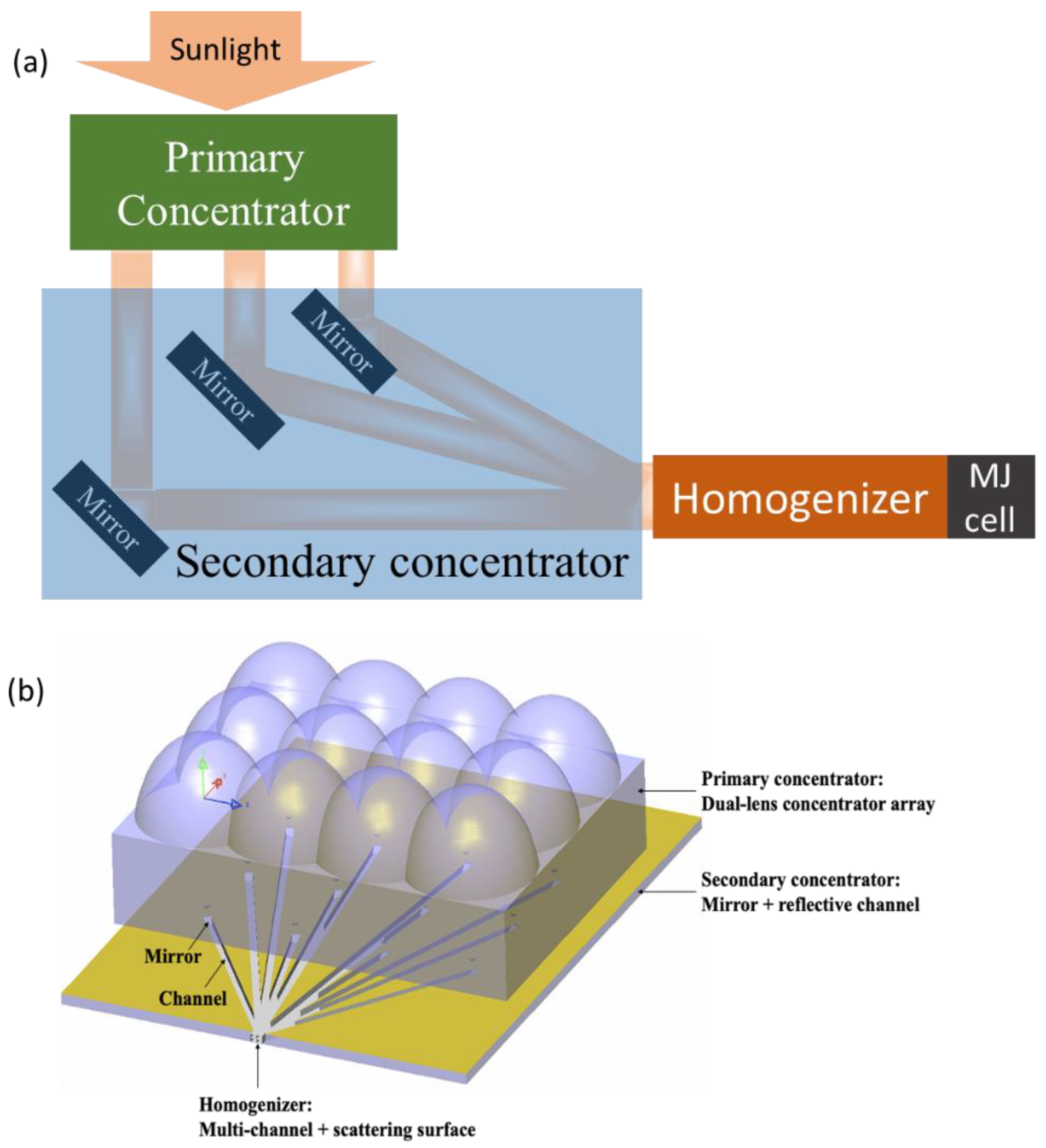
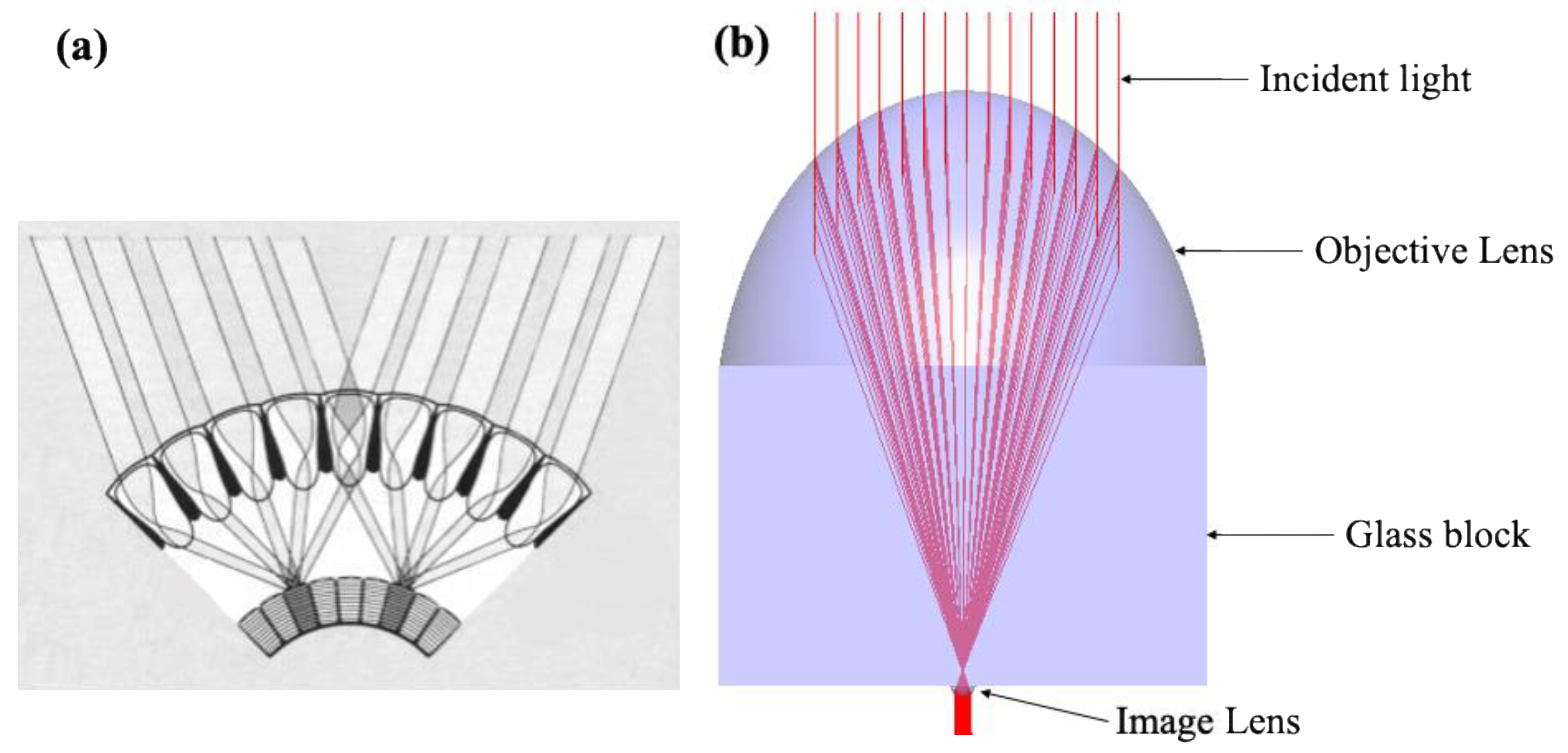
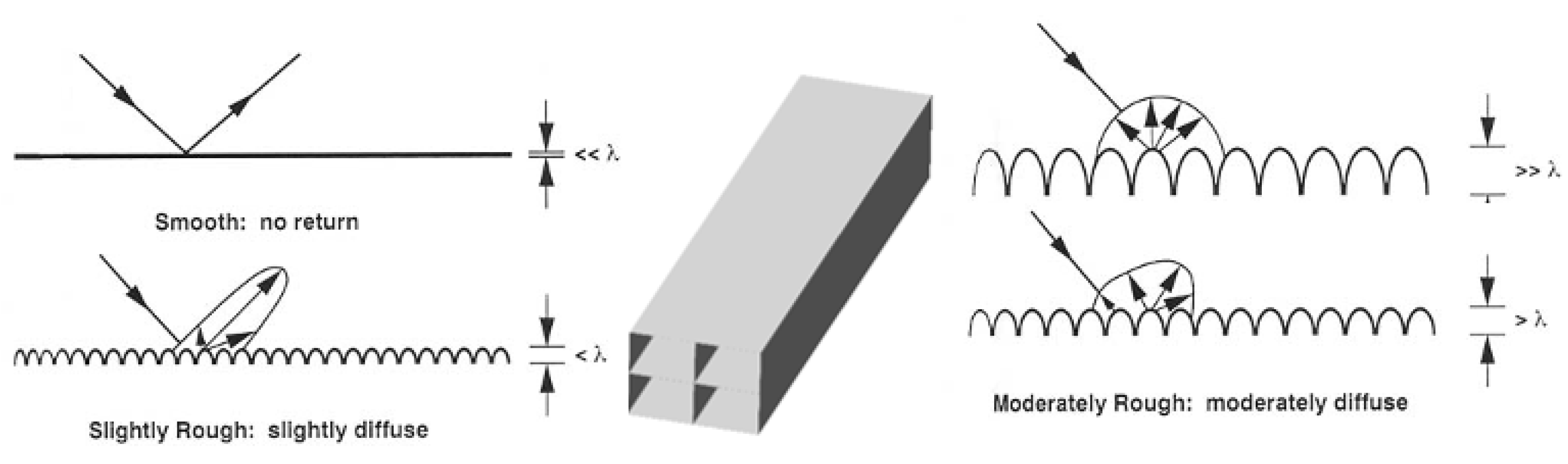

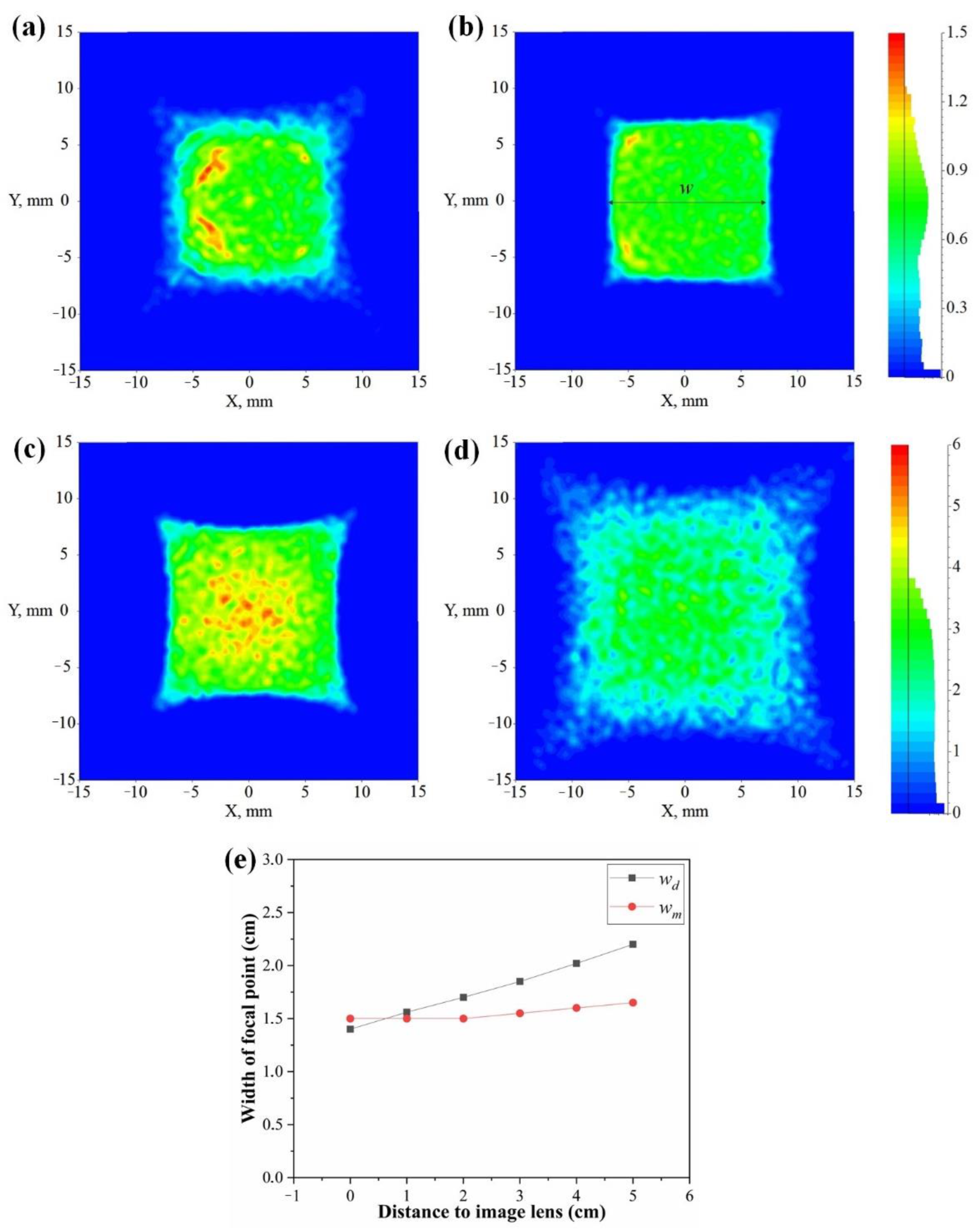
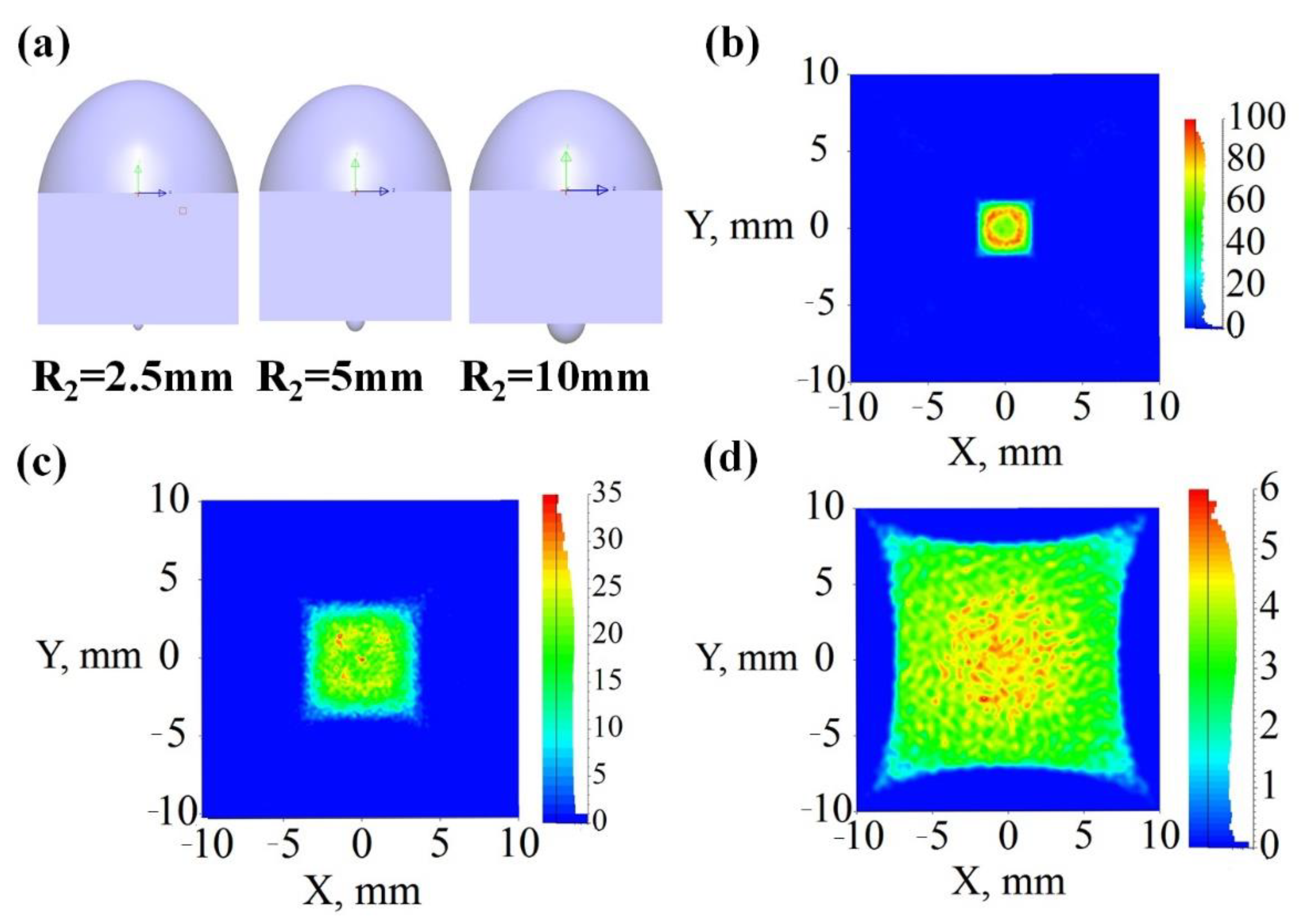
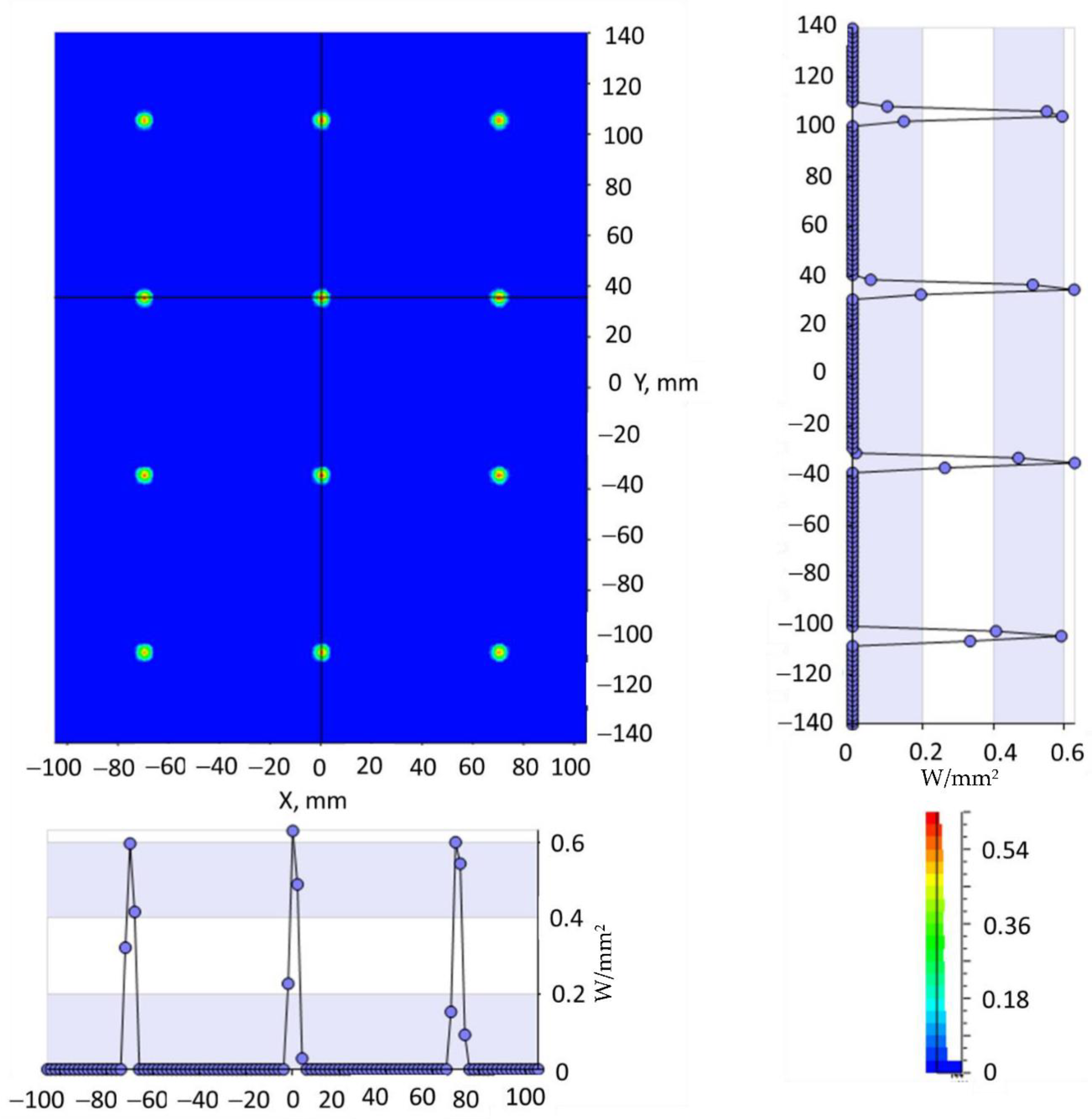

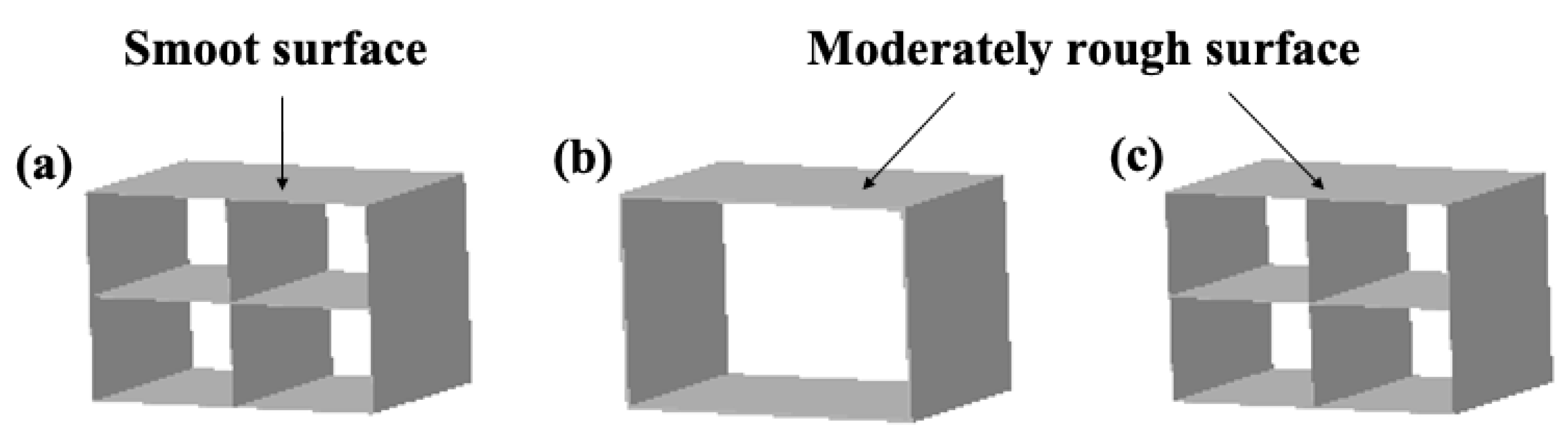
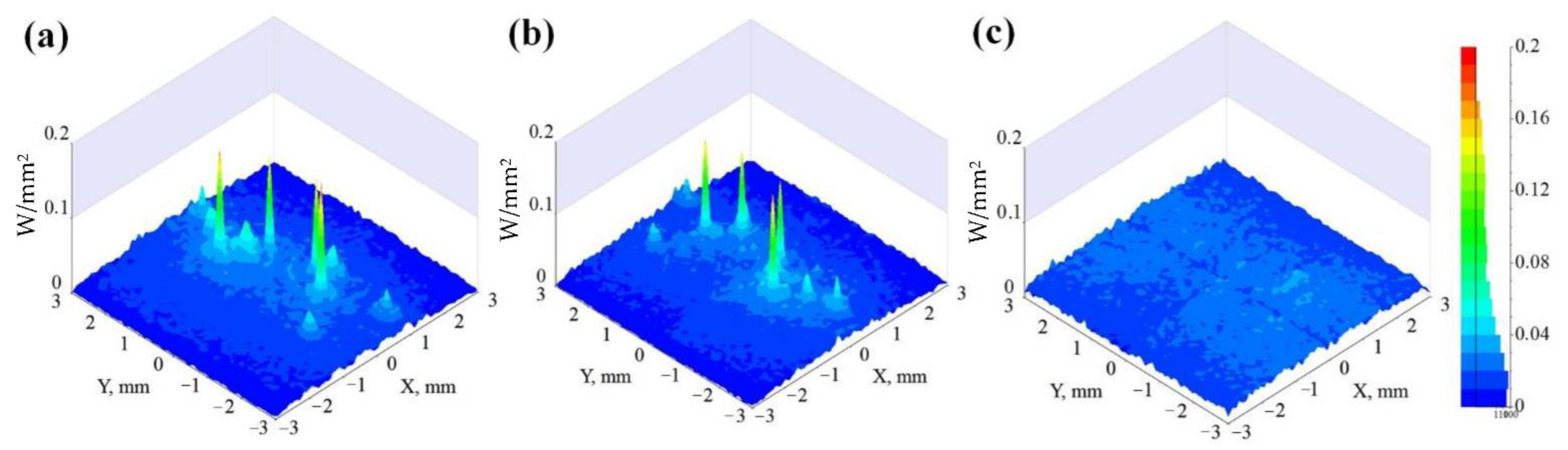
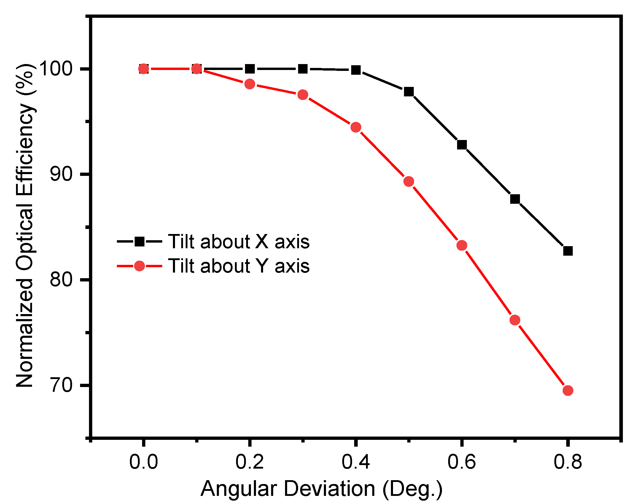
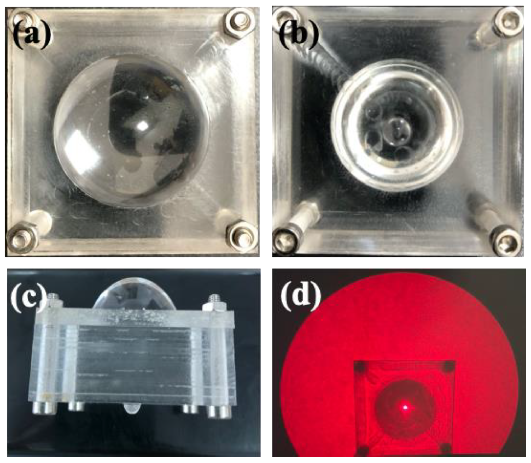
Publisher’s Note: MDPI stays neutral with regard to jurisdictional claims in published maps and institutional affiliations. |
© 2022 by the authors. Licensee MDPI, Basel, Switzerland. This article is an open access article distributed under the terms and conditions of the Creative Commons Attribution (CC BY) license (https://creativecommons.org/licenses/by/4.0/).