Article

Improvement of Stability in an Oscillating Water Column Wave Energy Using an Adaptive Intelligent Controller

1
School of Electronic and Electrical Engineering, Minnan University of Science and Technology, Quanzhou 362700, China
2
Fujian Key Laboratory of Industrial Automation Control Technology and Information Processing, Fuzhou 362700, China
*
Author to whom correspondence should be addressed.
Energies 2023, 16(1), 133; https://doi.org/10.3390/en16010133
Submission received: 13 October 2022 / Revised: 19 December 2022 / Accepted: 19 December 2022 / Published: 23 December 2022
(This article belongs to the Section A3: Wind, Wave and Tidal Energy)

Abstract

:
Presently, among the global ocean energy technologies, the most conventional one is the wave energy power generation device based on the oscillating water column (OWC) wave energy converter. Given the fluctuation and randomness of waves and the complexity of the current power grid, the dynamic response of grid connections must be considered. Furthermore, considering the characteristics of the wave energy converter, this paper proposed an adaptive intelligent controller (AIC) for the permanent magnet synchronous generator (PMSG) in an OWC. The proposed controller includes a grey predictor, a recurrent wavelet-based Elman neural network (RWENN), and an adaptive critical network (ACN) to improve the stability of OWC power generation. This scheme can increase the maximum power output and improve dynamic performance when a transient occurs under the operating conditions of random wave changes. The proposed AIC for the PMSG based on OWC has a faster response speed, a smaller overshoot, and better stability than the traditional PI controller. This further verifies the availability of the proposed control strategy.

1. Introduction

In recent years, due to increasingly severe serious environmental problems and the global crisis, reducing energy shortage, learning how to reduce carbon emissions, optimizing the energy structure, and decreasing the dependence on traditional fossil energy have become the focus of global attention [1,2]. To solve these problems, the field of development has been expanded to renewable energy using various methods, such as the solar photovoltaic maximum power point tracking method using variable weather parameters and an ocean wave energy power control of an intelligent controller based on an optimization algorithm [3,4,5]. Water occupies 71% of the earth’s area, and 97% of the water is concentrated in oceans. The ocean contains abundant energy and resources. With the increasing attention of the international community on ocean energy and the continuous progress of ocean development technology, the ocean has become a hot target for the research and development of renewable resources. At present, ocean energy power generation is mainly divided into wave energy power generation, ocean current energy power generation, tidal energy power generation, ocean temperature difference energy power generation conversion, and salt difference energy, among which wave energy is one of the most abundant ocean energy resources. In recent years, oscillating water-column (OWC) wave energy has been one of the most mature advanced technologies. Furthermore, researchers from various countries have developed various wave power generation devices [6,7]. As the wave speed changes with the climate or season, a turbine is used to convert the wave energy of the ocean current into power energy through the drive system to drive the power generator. This also changes with the wave speed, causing instantaneous changes in power and impacting the power quality of the grid. Under different operation modes, variations in wave speed have different effects on the quality of power. Due to the increasing capacity of wave power generation in recent years, the impact of wave generator operation on the power system has gradually attracted attention. Therefore, the permanent magnet synchronous generator (PMSG) is directly connected with the wave energy conversion device to improve the power generation efficiency of the wave power generation device [7,8,9], The PMSG uses permanent magnet excitation without an external excitation device, reducing excitation loss. Moreover, it does not need a reversing device; hence, it has the advantages of high efficiency and a long service life. The size and weight of the PMSG are only one-third and one-fifth, respectively, of traditional generators, such as the squirrel cage induction generator and the synchronous generator (which has equal power) [2]. Since the PMSG has the operating characteristics of synchronous and permanent magnet motors, additional pole pairs can be designed. These pole pairs are suitable for directly connecting the generator and the wave-energy-conversion device. To increase the power generation efficiency of the wave power generation device and handle various dynamic and transient responses during grid connection, effective control methods should be adopted. Following the principle of the wave-capture device, the control strategies of the wave power generation system mainly include the reactive and latch control strategies. Some of the literature [10,11,12,13,14] proposed several intelligent control algorithms and applied various renewable energy power generation control and grid connection research topics.
Furthermore, some studies proposed using intelligent control schemes in wind power generation and solar power generation systems, such as various forms of fuzzy control algorithms, neural networks, and fuzzy combination controllers, such as fuzzy/LQR hybrid controllers and genetic algorithms based on diverse local solutions. Nevertheless, wave power generation systems have a few intelligent control strategies. In the 1990s, Dr Elman proposed one of these strategies, a new neural network for speech processing, and named it the Elman neural network (ENN) [15]. Due to its unique dynamic performance, it has been widely used in fault prediction and in the power operation control of power grids [16,17,18]. However, for an unpredictable renewable energy power generation system, the typical ENN cannot accurately approximate the high-order dynamic system of the renewable energy power generation system, resulting in the slow response and poor accuracy of the systems parameter convergence. Therefore, the typical ENN is not suitable for wind or wave energy conversion devices with high randomness. Consequently, to maintain the good dynamic performance of ENN and improve the convergence, previous studies [19,20,21] proposed several improved ENNs to overcome this problem. The authors of [19] proposed an improved ENN, that is mainly used to dynamically track the gradient in the parameter space and enabled the network to model in dynamic systems the first order. GWave company is developing the world’s largest wave power generation device, with an installed capacity of 900 MW in the UK. Therefore, ref. [8] proposed a moment-based energy maximization control strategy for OWC to maximize energy. Ref. [9] proposed a second-order sliding mode control algorithm for control valves to improve power conversion.
Therefore, to provide improved control and stability to a PMSG-based OWC, we present an adaptive intelligent controller (AIC) for suppressing various power system oscillations when the OWC is connected to the power grid. The AIC includes a gray predictor, a recurrent wavelet-based Elman neural network (RWENN), and an adaptive critic network (ACN). Due to the random characteristics of waves, the influence of variations in speed of the PMSG in various emergencies must be considered. Hence, the varying speed of the OWC is used to control the electromagnetic torque driven by the PMSG. From the simulation results, the AIC method proposed in this paper can improve the transient phenomena of wave power generation systems when the operating points of the power grid change extensively.
The contributions of this study are listed as follows:
(1)
Presently, the problem of renewable energy grid connection is becoming increasingly important. However, few studies have researched the dynamic and transient phenomena after wave power generation is connected to the power system. Hence, we examined these phenomena.
(2)
To increase the robustness of the PMSG-based OWC, an intelligent control algorithm was proposed.
(3)
The system generates the signal to the PMSG-based OWC so that the PMSG can better control the power system and have a better dynamic response than other intelligent control algorithms.

2. Analysis of System Models

2.1. Configuration of the PMSG-Based OWC System

The system configuration studied in this paper is a 120 MW-based PMSG wave power farm. The principle and structure of the OWC wave energy conversion device are shown in Figure 1, mainly including the forebay, air chamber, air duct, and turbine. Under incident waves, the force acting on the water column in the air chamber oscillates, making the air above the water column push the air duct repeatedly so that the turbine can generate mechanical energy for power generation [22,23]. The device is characterized by the resonance effect of waves to strengthen the water column oscillation. Consequently, the water column in the air chamber moves up and down due to the push of waves. Figure 1 shows that the OWC drives the input transmission shaft to rotate due to the upward lifting movement caused by the wave impact, thus driving the generator to rotate. The PMSG-OWC system comprises a converter of wave power generation speed control and a PWM voltage source converter (VSC (Gen.) and VSC (Grid); Figure 1). It is a back-to-back voltage source converter. Moreover, the voltage of the DC link and the power and frequency transmitted to the power grid are controllable. The VSC voltage-oriented vector control design and the control block diagram of PMSG are shown in [24,25].

2.2. Turbine Model

Since the airflow generated by the wave energy of the OWC reciprocates, this study used the Wells turbine as the drive of OWC, which can make the turbine rotate in the same direction in the airflow channel under the action of two-way airflow, thus driving the generator to generate electricity. The mechanical torque (Γm), torque coefficient (Γc), and incidence angle of air pressure on the turbine blade (φ) converted from wave energy are as follows [3]:
Γ m = k Γ c υ A 2 + υ B 2
Γ c = C 8 + C 1 φ 3 C 2 φ 2 + C 3 φ C 4 C 5 φ 2 + C 6 φ C 7
ϕ = tan 1 υ A υ B
where k is the coefficient of the employed Wells turbine, υA is the axial velocity (m/s), υB is the blade tip speed (m/s), and C1C8 are constant. Furthermore, the torque (Γm) of the Wells turbine is delivered to the shaft of the PMSG.

2.3. PMSG

The PMSG drive system model is represented as follows [26,27]:
d ω r L d = Γ m Γ e B m ω g J e q
where ωr is the rotor speed of the generator (rad/s), Γe is the electromagnetic torque, Bm is the rotational viscosity coefficient, and Jeq is the equivalent inertia moment of the unit.
The stator voltage model of PMSG in the d–q synchronous rotating coordinate system is written as follows:
d i d s d t = R s L d i d s + ω q L q i d s L d + u d s L d
d i d s d t = R s L q i q s ω e L d i d s L q ϕ f L q + u q s L q
Furthermore, the electromagnetic torque is described as follows:
Γ e = 1.5 n p ϕ f i q s + L d L q i d s i q s
where i d s , i q s , u d s , u q s , L d , and L q are the stator current, stator voltage, and equivalent inductances of the PMSG, respectively. The subscripts d and q are the components of the direct axis and quadrature axis of these parameters in the dq coordinate system, respectively. For PMSG, Ld = Lq. R s is the stator resistance, ϕ f is the permanent magnet magnetic chain, and ω e is the electrical angular velocity.

3. Design of Adaptive Intelligent Controller (AIC)

The AIC comprises the ACN, RWENN, and grey predictor. AIC input signal is generator rotor speed deviation Δωr. Moreover, RWENN has an additional feedback unit, the input from the hidden layer output to the feedback link. This link stores the signal output through the hidden-layer neurons at the previous time so that the network can store relevant information and that it has the characteristics of dynamic memory. The RWENN needs an appropriate training signal to train its network with link weights. Hence, in this study, we used ACN to identify the training signal to RWENN. The proposed AIC can provide near optimal results for complex specific dynamic systems and related cost functions to solve the objective function value of the Hamilton–Jacobi–Bellman equation of optimal control were used to obtain optimal control variables, as in a previous publication [28].

3.1. Grey Predictor Modeling Approach

The Grey Model (GM) is generally expressed as GM (d, r), which means modeling r variables with n-order differential equations [3,29]. Here, a GM model was proposed primarily to treat discrete data scattered on the axis as a sequence of continuously changing variables. The model adopted the method of accumulation and subtraction, which can offset most of the random errors and strengthen the influence degree of known factors to find the regularity. Finally, it can build a differential equation with time as a variable to determine the parameters of PMSG to predict the input variables of RWENN.
To predict the next y(i + k), k 1. The initial data Y 0 = y 0 1 ,   y 0 2 , ,   y 0 i are given, where y(i) corresponds to the system output of time i. Hence, the AGO generates a new sequence Y 1 = y 1 1 ,   y 1 2 , ,   y 1 n from Y 0 , which is derived as follows:
y 1 k = x = 1 n y 0 x ,     k = 1 ,   2 ,   , i
From Y 1 , we can form a first-order differential equation, as:
d y 1 d t + d y 1 = r
where d and r in GM (1, 1) are estimated parameters, which are the development coefficient and grey action quantity, respectively.
Hence,
y ^ 1 n + 1 = y 0 1 r d e d n r d ,     k = 1 ,   2 ,   , i
y ^ 0 n + 1 = y 1 n + 1 y ^ 1 n
Here,
d r = Ζ T Ζ 1 Ζ T
Ζ = 0.5 y 1 1 + y 1 2 1 0.5 y 1 2 + y 1 3 1 0.5 y 1 n 1 + y 1 n 1
Y = y 0 2 ,   y 0 3 , ,   y 0 n T and y ^ 1 n + 1 are the y(n + 1) predicted values at time n + 1. The GM (1, 1) model uses original discrete non negative data columns. Therefore, Deng [26] added sequence deviation to the proposed scheme so that all elements could avoid negative effects.
Figure 1 shows that the GM uses the current error e(n) to predict the future error e(n + 1) of the subsequent control action; that is, the control action depends on the prediction error before it occurs.

3.2. Recurrent Wavelet Elman Neural Network (RWENN)

Figure 2 shows the five-layer RWENN structure and the AIC connection mode. The feedforward connection of the network can be realized using five layers of neurons. The direction of transmission from the input signal to the output signal shows that the input layer has i nodes connected to the hidden layer of j nodes. However, the hidden layer is connected to u node output neurons. According to the transmission direction of signal feedback, the output layer is connected to the output feedback layer of k nodes through a delay z−1 to the hidden layer. The hidden layer is connected to the context layer of r nodes through a delay. Furthermore, through the delay, it connects to the input of the hidden layer through its own delay.
The first layer is mainly for signal transmission. Thus, its input Xi (X1 and X2) is equal to its output Oi for the nth neuron in the input layer. The inputs Xi are e(n + 1) and ce(n + 2) by the grey on-line dynamic prediction of the Grey predictor. The second layer is a hidden layer. The transfer function in this layer is a tangent double bending transfer function (tansig). The function of this second layer is to increase the search space. All neurons generate different wavelet functions by setting different translations and scalings to improve the search ability. Because the first derivative of the Gaussian function is similar to the wavelet, this paper selected the Gaussian function as the parent wavelet. Its input and output are as follows.
The first layer is mainly for signal transmission. Thus, its input Xi (X1 and X2) is equal to its output Oi for the nth neuron in the input layer. The inputs Xi are e(n + 1) and ce(n + 2) by the grey on-line dynamic prediction of the Grey predictor. The function of this second layer is to increase the search space. All neurons generate different wavelet functions by setting different translations and scalings to improve the search ability. Because the first derivative of Gaussian function is similar to the wavelet, this paper selected the Gaussian function as the parent wavelet. The input I j n and output O j n of the jth node of the hidden layer are as follows:
I j n = O i n λ j n γ j n
O j n = f I j n
where λ j and γ j are the associated translation and dilation parameters of the wavelet function. The f · is the Mexican Hat wavelet function of the first derivative of the Gaussian function. By reasonably selecting the parameters in the first derivative of the Gaussian function, the function has the approximation property as shown below:
f · = 1 x 2 exp 1 / 2 x 2
The sum of the firing strengths ( ρ j ) of the second layer neurons from the input layer, the context layer, and the output feedback layer can be described as follows:
ρ j = i = 1 2 O i · W i j + r = 1 n O r · W r j + k O k · W k j
where Wij is the connective weights of the input neurons to hidden neurons. The connective weights of the context neurons to the hidden neurons and the output feedback neurons to the hidden neurons are W r j and W k j , respectively.
The output nodes of layers 3, 4, and 5 are
O r n = β O r n 1 + O j n 1
O k n = exp O u n 1 2
O u = j = 1 n W j y O j
where the O r , O k , and O u are the output nodes of layers 3, 4, and 5. β is the self-connection feedback gain, 0 α 1 . W j y is the connection weight between the hidden layer and output layer, which is set as one.
Once RWENN is initialized, the system can be trained using supervised learning based on the gradient descent method. The derivation process is the same as that of the BP algorithm. It is used to adjust the weight value of RWENN by using training mode. The correction amount of the weight added value is proportional to the estimated value of the negative gradient. By recursively applying the chain rule, the gradient vector faces the opposite direction to the output direction of each neuron to calculate the error term of each layer. To describe the RWENN on-line learning method, the cost function Ec is defined as in [12]. More detailed online parameter learning algorithms of each layer are introduced in [12,29].

3.3. Adaptive Critic Network (ACN)

In practical application, the accurate calculation of system Jacobian E c / Δ O u of RWENN is too difficult [2,29]. ACN is mainly for the execution network at the current time; that is, the output signal of RWENN makes a “residual cost” estimate. Therefore, in this paper, an ACN was used to identify the sensitivity of RWENN B c / Δ ω r to understand the cost-to-go associated with the OWC system. When the OWC system is disturbed or the operation point changes, this capability is very important for the real-time optimal control operation. ACN can make RWENN have a more accurate training process by identifying the sensitivity of RWENN. The operation cost-to-go function Bc of Bellman’s dynamic programming equation estimated by ACN is [2]:
B c n = l = 0 Ψ l μ n + l = μ n + l = 0 Ψ l μ n + 1 + l = μ n + Ψ · B c n + 1
where the utility function μ n is an important factor used to form the optimal cost-to-go, and Ψ represents the discount factor (0~1). The utility function of the critic network μ n includes μ 1 n , and μ 2 n is
μ n = μ 1 n + μ 2 n
μ 1 n = Δ ω r n + Δ ω r n 1 + Δ ω r n 2
μ 2 n = Δ i q s n + Δ i q s n 1 + Δ i q s n 2
The ACN structure in Figure 3 has a four-layer feed-forward network structure. The node outputs of ACN from the first layer to the fourth layer are O1i (i nodes), O2j (i nodes), O3g (g nodes), and O4h (h nodes) respectively. The outputs of each layer are as follows:
O 1 i n = I 1 i n ,   I i = [ Δ ω r ( n ) ,   Δ ω r ( n 1 ) ,   ,   Δ i q s ( n 2 ) ,   1 ] ,   I = 1 ,   ,   8
O 2 j n = 1 + exp ϵ 1 ,     ϵ = i = 1 8 O 1 i · w a b
O 3 g n = J g n = g = 1 2 O 2 j ,     g = 1 , 2        
O 4 h n = O 3 g = B c n
where Ii is the input vector of layer 1. wab is the connecting weights of the input layer to hidden layer.
The training process ensures that the critic network provides optimal control to minimize the Bc(n), which enables the RWENN controller to provide the optimal control signal i q s * to the OWC-PMSG in this paper.
The derivatives of the left and right sides of the Equation (21) are calculated by the Bellman equation:
B c n Δ ω r n = μ n Δ ω r n + Ψ B c n + 1 Δ ω r n
When the network converges to the derivative of the cost function Bc of the optimal control with respect to the state, the above equation is satisfied. In practical application, it is expected that each state of the system will satisfy the above equation. Therefore, the error function of ACN is defined as [2]:
E c = 1 2 e c 2
e c = B c n Δ ω r n μ n Δ ω r n Ψ B c n + 1 Δ ω r n
and
B c n + 1 Δ ω r n = B c n + 1 X i k + 1 X i k + 1 Δ ω r n
The connecting weights of ACN can be trained by recursively applying the chain rule as
w a b k + 1 = w a b k η a b · E w a b
where η a b   are the learning rates of w a b of RWENN.

4. Time-Domain Simulations and Discussion

All simulation results were completed in MATLAB 2016b/Simulink software. The simulation in this paper was divided into three research cases to simulate the dynamic and transient performances of the OWC–PMSG system (Appendix A) under various scenarios. To verify the robustness of the proposed AIC, the designed PID, RWENN, and AIC methods were compared through various tests. The designed comparison PID method [30,31] in this paper used root locus to determine parameters to improve the stability of the system. After linearizing the nonlinear system equation at a specific operating point, a set of linear system equation matrices can be obtained. This method is better than the traditional PID method. The other comparison method is RWENN (without grey predictor and ACN). The performance of each controller in the PMSG-based OWC control is shown in Figure 4, Figure 5 and Figure 6.

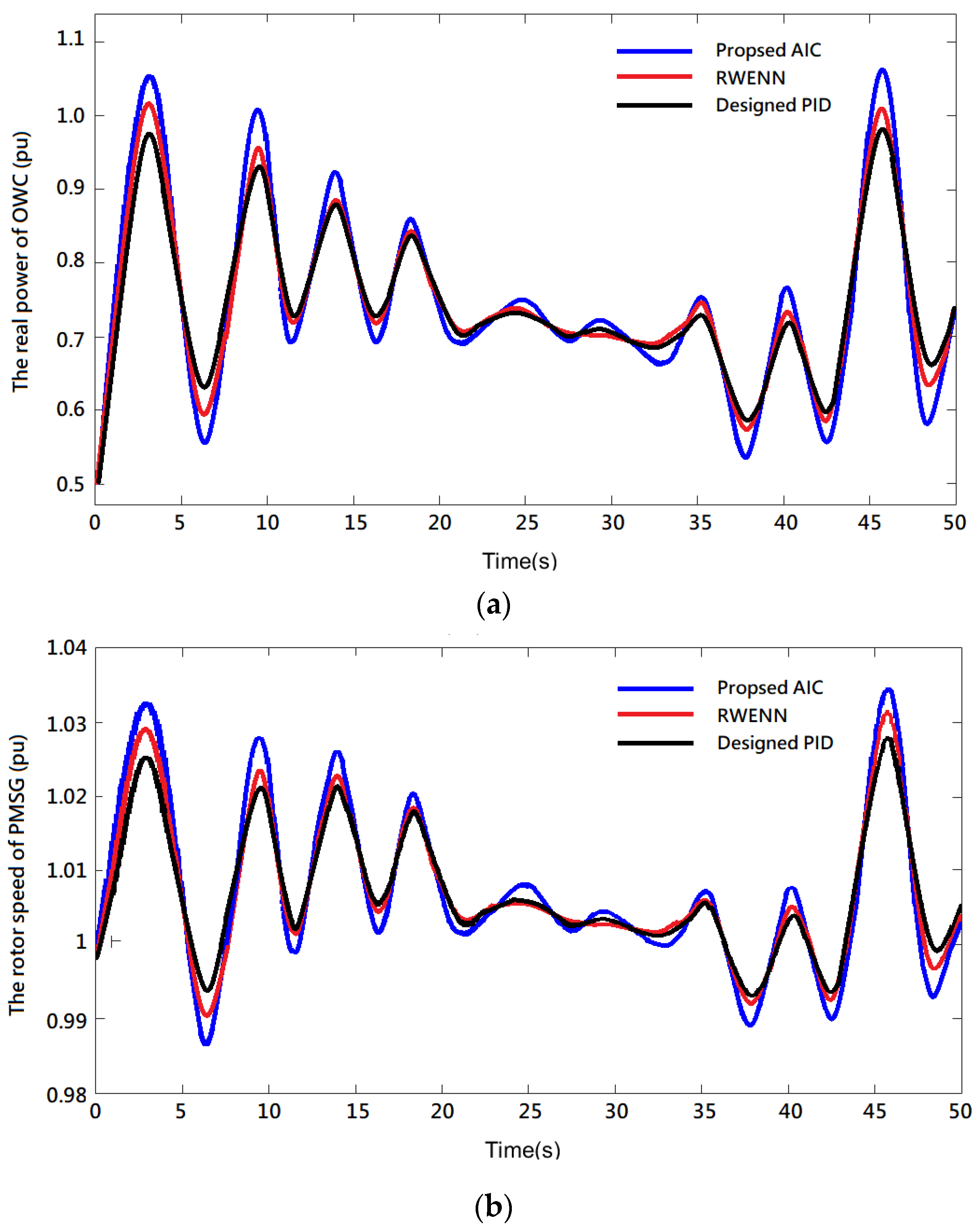
4.1. Random Variable Velocities of OWC

The time domain simulation of the OWC operates with a constant load under sufficient wave conditions. The input of the OWC waveform response here is the dynamic response generated by the water column in the air chamber moving up and down due to the impulse of random waves (55–115 KW/m), and the turbine drives the PMSG. The PMSG-based OWC output power transient responses of the studied system subject to a wave speed change are shown in Figure 4. The simulation of the dynamic response of the wave speed varied randomly between 0 and 50 s. Figure 4a shows that the highest real power distributions of AIC, RWENN, and the designed PID are 1.072, 1.01, and 0.91 pu, respectively. Compared with the RWENN controller, AIC and PID improved by 6.1% and 17.8%, respectively. Figure 6b shows the real power variations during the speed change and the real power variations of the PMSG. Thus, the proposed method can track faster and its output power is more stable, leading to better control than the designed PID and RWENN. Figure 4a,b shows that the AIC method can quickly and accurately track the maximum output power of the PMSG of OWC. Moreover, when the real power changes, the reactive power fluctuates (Figure 4c). Compared with RWENN and the designed PID controller, AIC has a smaller transient response, smaller oscillation, and an optimal control response.

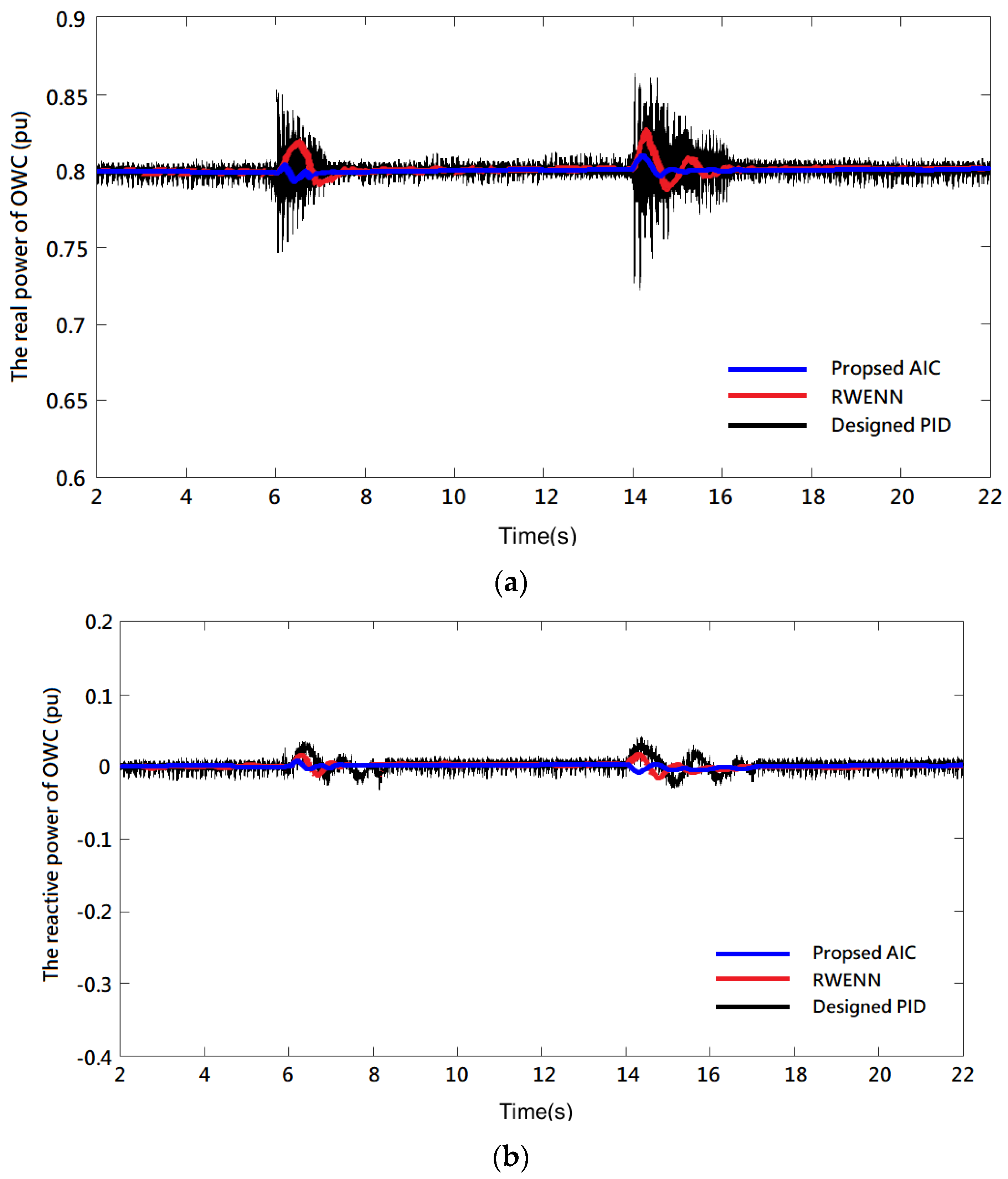
4.2. Load Disturbance

When the input wave energy was fixed at 87 KW/m, the simulated load quickly increased from 0.4 pu to 1 pu at the sixth second and decreased from 1 pu to 0.3 pu at the fourteenth second. Figure 5a shows that when the load changed at the sixth second and the fourteenth second, the real power response of the AIC method had a small amplitude change and a faster convergence time than the designed PID and RWENN, and it recovered to a stable state between 7 and 15 s. Although these three methods can be restored to the steady state, the actual power controlled by the designed PID method had the largest amplitude oscillation, the most obvious ripple, and the slowest convergence time due to the level of load changes compared to the other two methods. The next is RWENN. The reactive power results in Figure 5b show that the three designed effectively suppressed amplitude oscillations when the load changed. However, the results show that the reactive power response with the AIC method had a small amplitude change and a faster convergence time than the other two methods, while the PID convergence time was the slowest. Figure 5c shows that when AIC was used, the time the grid-side voltage took to recover to stability was the fastest among the three methods, and the bus voltage was kept at 1 pu. The dynamic response of the grid frequency is shown in Figure 5d. Similarly, the results in Figure 5d show that when the load changed at the sixth and fourteenth second, the response of the OWC system with AIC had the smallest frequency oscillation and fastest convergence time compared to the designed PID and RWENN.

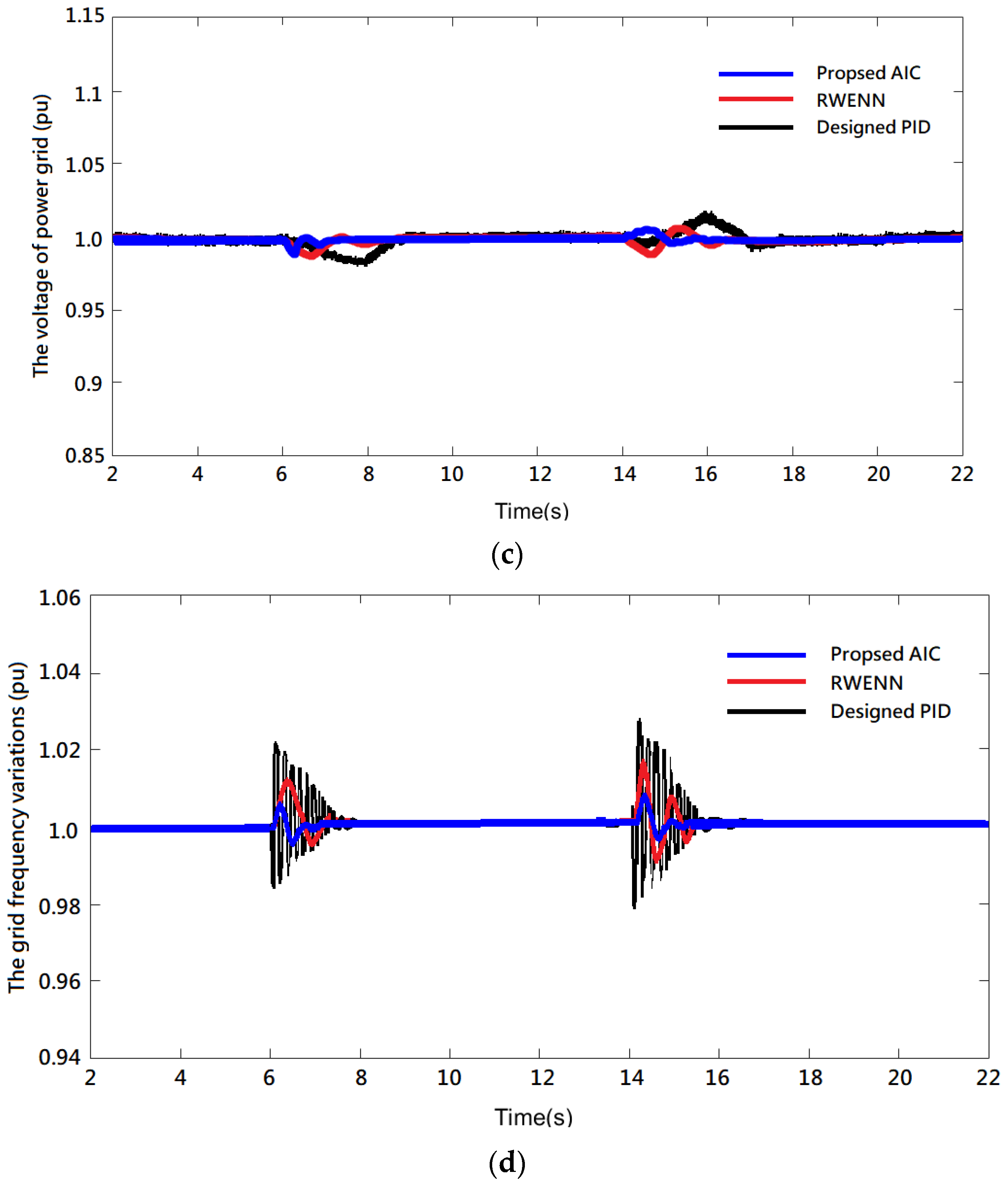
4.3. Three-Phase Short-Circuit Fault

During load disturbance, the input wave energy was 87 KW/m. The transient phenomenon of a three-phase short circuit grounding fault was simulated on the grid side. When the fault occurred at 3 s, the fault lasted for 0.1 s. A change in each parameter was observed. Figure 6a,b shows the transient response of the OWC real power and reactive power, respectively. Compared with the designed PID controller and RWENN, AIC had the best effect of oscillation suppression. After the fault, the real power transient phenomenon can reach stability at about 4.5 s, while the reactive power transient phenomenon can reach stability at about 4.4 s. Furthermore, the real and reactive power controlled by the proposed AIC are the minimum overshoot. Figure 6c shows that, when a fault occurred, it greatly impacted the bus voltage on the grid side. The bus voltage with AIC can maintain the minimum voltage change. The bus voltage with REWNN control reached stability at 6 s after the fault ended, while the voltage with designed PID control continued to oscillate until it reached stability at 9.4 s after the fault ended. Figure 6d shows the change of system frequency under the transient phenomenon. Moreover, it shows that AIC had the least frequency oscillation and the fastest convergence time compared to the designed PID and RWENN. This can be observed in the various responses in Figure 6. Therefore, when a fault occurred, the AIC method designed was the most effective way to reduce the bus voltage oscillation and improve the transient stability of the system compared to RWENN and the designed PID.
To further verify the robustness of the AIC, a traditional PI controller, function link-based Wilcoxon radial basis function network (FLWRBFN) [7], and recursive cerebellum model articulation controller (RCMAC) [3] were added to compare the results of overshoot and convergence time of active power and grid voltage oscillations at the end of the fault. Furthermore, this compared the other five methods for real power oscillation and transient response of grid voltage amplitude and quantified each performance index in Table 1 and Table 2. The tables show that, compared to the other methods, PMSG-based OWC controlled by AIC has the best precision and a faster convergence speed than the other methods. These results show that AIC has better control of nonlinear dynamic systems.

5. Conclusions

The AIC method proposed in this paper had a significant effect on the control of PMSG-based OWC, which also proves that this method is feasible. Therefore, the power control effect and stability of the OWC grid connected power grid are improved. From the simulation results of this study, it is shown that the proposed AIC can achieve the maximum power performance in the power tracking control of wave power generation. When the OWC is in the cases of load changes and three-phase short circuit fault, the performance of the dynamic and transient response also proves the effectiveness of the proposed control scheme. From the results, whether the load changes or three-phase faults occur, the oscillations of the real power, reactive power, grid frequency, and grid voltage can be effectively suppressed, greatly reducing the harm caused by the power oscillation disturbance. As far as the performance of the wave energy conversion system is concerned, when the ocean waves with high randomness are unstable, the control of AIC can effectively stabilize the operation of the power grid and improve security. Because this method uses the grey predictor to monitor the input signal of RWENN and uses ANC to generate the back-propagation training item, compared to other methods, it proves the superiority and robustness of this method compared to the OWC control.

Author Contributions

Z.W. modeled the overall architecture and proposed new concepts and applications. S.W. adjusted the program and verified the simulation results. K.-H.L. made contributions to the development of algorithms and prepared the first draft of the manuscript to be submitted. All authors have read and agreed to the published version of the manuscript.

Funding

The project was supported by the Natural Science Foundation of Fujian Province of China (No. 2021J01531).

Data Availability Statement

Data are contained within the article.

Conflicts of Interest

The authors declare no conflict of interest.

Appendix A

Table A1. Simulation parameters of PMSG-based OWC.
PMSG-Based OWC
Turbine: SPMSG = 4 × 30 MW, 4.65 A, 3000 rpm, Jeq = 1.45 × 10⁻³ Nms2, Bm= 6.63 × 10⁻³ Nm s/rad, V = 15 KV, PF = 0.98, f = 60 Hz, Ld = Lq = 6.5 mH. ϕ f = 6.616 × 10⁻³ Wb, C1 = 0.22, C2 = 115, C3 = 0.37, C4 = 4.88, C5 = 15.36, C6 = 0.0068, C7 = 0.22, C8 = 10. T1: V1 = 0.69 kV, R1 = 83 × 10−3 pu, L1 = 0.025 pu, V2 = 23 kV, R2 = 83 × 10−3 pu, L2 = 0.025 pu, VSC: Cdc = 0.7 pu, Rs = 124.459 mΩ, Cs = ∞, Ron = 0.1 mΩ, Vf = 2 V, Vfd = 1 V, Thyristor valves firing average time Td = 4 × 10⁻³, Kp_Grid-side = 1, Ki_Grid-side = 100, Kp_Rotor-side = 0.3, Ki_Rotor-side = 8, Droop Xs = 0.02 pu. LCL filter: L1 = 650 μF, L2 = 28.5 μF, C = 20 μF. Instantaneous AC over current = 10 pu. Maximum AC Current: I1max = 1.1 pu, Delay time = 5 s.

References

  1. Ou, T.C.; Lu, K.H.; Huang, C.J. Improvement of transient stability in a hybrid power multi-system using a designed NIDC. Energies 2017, 10, 488. [Google Scholar] [CrossRef] [Green Version]
  2. Lu, K.H.; Chen, H.C.; Su, Y.; Xu, Q. Design of an Intelligent Damping Controller of STATCOM with HVDC for Large Offshore Wind Farm. J. Mar. Sci. Technol. 2018, 26, 228–239. [Google Scholar]
  3. Lu, K.-H.; Hong, C.-M.; Han, Z.; Yu, L. New Intelligent Control Strategy Hybrid Grey-RCMAC Algorithm for Ocean Wave Power Generation Systems. Energies 2020, 13, 241. [Google Scholar] [CrossRef] [Green Version]
  4. Linda, S.; Rachel, S.; Thomas, D. What drives energy consumers: Engaging people in a sustainable energy transition. IEEE Power Energy Mag. 2018, 16, 20–28. [Google Scholar]
  5. Li, S.; Chen, K.; Li, Q.; Ai, Q. A Variable-Weather-Parameter MPPT Method Based on Equation Solution for Photovoltaic System with DC Bus. Energies 2022, 15, 6671. [Google Scholar] [CrossRef]
  6. Bacelli, G.; Nevarez, V.; Coe, R.G.; Wilson, D.G. Feedback Resonating Control for a Wave Energy Converter. IEEE Trans. Ind. Appl. 2019, 56, 1862–1868. [Google Scholar] [CrossRef]
  7. Lu, K.-H.; Hong, C.-M.; Tan, X.; Cheng, F.S. Novel Intelligent Control Technology for Enhanced Stability Performance of an Ocean Wave Energy Conversion System. Energies 2021, 14, 2027. [Google Scholar] [CrossRef]
  8. Nicolás, F.; Giordano, S.; Alessandro, A.; John, V.R. Nonlinear Energy-Maximizing Optimal Control of Wave Energy Systems: A Moment-Based Approach. IEEE Trans. Control. Syst. Technol. 2021, 29, 2533–2547. [Google Scholar]
  9. Gaebele, D.; Magaña, M.E.; Brekken, T.K.A.; Henriques, J.C.C.; Carrelhas, A.; Gato, M.C. Second Order Sliding Mode Control of Oscillating Water Column Wave Energy Converters for Power Improvement. IEEE Trans. Energy Convers. 2021, 12, 1151–1160. [Google Scholar] [CrossRef]
  10. Kaur, K.; Rana, R.; Kumar, N.; Singh, M.; Mishra, S. A colored petri net based frequency support scheme using fleet of electric vehicles in smart grid environment. IEEE Trans. Power Syst. 2016, 31, 4638–4649. [Google Scholar] [CrossRef]
  11. Ahmet, S.P.; Beste, B.; Kemalettin, E. Genetically Optimized Pitch Angle Controller of a Wind Turbine with Fuzzy Logic Design Approach. Energies 2022, 15, 6705. [Google Scholar]
  12. Wu, X.; Jiang, S.; Lai, C.S.; Zhao, Z.; Lai, L.L. Short-Term Wind Power Prediction Based on Data Decomposition and Combined Deep Neural Network. Energies 2022, 15, 6734. [Google Scholar] [CrossRef]
  13. Elgammal, A.A.A. Adaptive fuzzy sliding mode controller for grid interface ocean wave energy conversion. J. Intell. Learn. Syst. Appl. 2014, 6, 53–69. [Google Scholar] [CrossRef] [Green Version]
  14. Lin, W.M.; Hong, C.M.; Huang, C.H.; Ou, T.-C. Hybrid control of a wind induction generator based on grey-elman neural network. IEEE Trans. Control. Syst. Technol. 2013, 21, 2367–2373. [Google Scholar] [CrossRef]
  15. Elman, J.L. Finding structure in time. Cogn. Sci. 1990, 14, 179–211. [Google Scholar] [CrossRef]
  16. Lin, F.J.; Teng, L.T.; Chu, H. Modified Elman neural network controller with improved particle swarm optimization for linear synchronous motor drive. IET Electr. Power Appl. 2008, 2, 201–214. [Google Scholar] [CrossRef]
  17. Lin, F.J.; Hung, Y.C. FPGA-based Elman neural network control system for linear ultrasonic motor. IEEE Trans. Ultrason. Ferroelect. Freq. Control 2009, 56, 101–113. [Google Scholar]
  18. Li, X.; Chen, G.; Chen, Z.; Yuan, Z. Chaotifying linear Elman networks. IEEE Trans. Neural Netw. 2002, 13, 1193–1199. [Google Scholar]
  19. Pham, D.T.; Liu, X. Training of Elman networks and dynamic system modelling. Int. J. Syst. Sci. 1996, 27, 221–226. [Google Scholar] [CrossRef]
  20. Mbede, J.B.; Huang, X.; Wang, M. Robust neuro-fuzzy sensorbased motion control among dynamic obstacles for robot manipulators. IEEE Trans. Fuzzy Syst. 2003, 11, 249–261. [Google Scholar] [CrossRef]
  21. Liu, H.; Wang, S.; Ouyang, P. Fault diagnosis based on improved Elman neural network for a hydraulic servo system. In Proceedings of the 2006 IEEE Conference on Robotics, Automation and Mechatronics, Bangkok, Thailand, 1–3 June 2006; pp. 1–6. [Google Scholar]
  22. Lu, K.H.; Hong, C.M.; Xu, Q. Recurrent wavelet-based Elman neural network with modified gravitational search algorithm control for integrated offshore wind and wave power generation systems. Energy 2019, 170, 40–52. [Google Scholar] [CrossRef]
  23. Wang, L.; Chen, Z.J. Stability Analysis of a Wave-Energy Conversion System Containing a Grid-Connected Induction Generator Driven by a Wells Turbine. IEEE Trans. Energy Convers. 2010, 25, 555–563. [Google Scholar] [CrossRef]
  24. Wang, L.; Truong, D.N. Dynamic Stability Improvement of Four Parallel-Operated PMSG-Based Offshore Wind Turbine Generators Fed to a Power System Using a STATCOM. IEEE Trans. Power Del. 2013, 28, 111–119. [Google Scholar] [CrossRef]
  25. Lin, F.J.; Liao, Y.H.; Lin, J.R.; Lin, W.T. Interior Permanent Magnet Synchronous Motor Drive System with Machine Learning-Based Maximum Torque per Ampere and Flux-Weakening Control. Energies 2021, 14, 346. [Google Scholar] [CrossRef]
  26. Swakshar, R.; Ganesh, K.V. Online learning control using adaptive critic designs with sparse kernel machines. IEEE Trans. Neural Netw. Learn. 2013, 24, 762–775. [Google Scholar]
  27. Zhang, Y.; Sun, H.; Guo, Y. Wind Power Prediction Based on PSO-SVR and Grey Combination Model. IEEE Access 2019, 7, 136254–136267. [Google Scholar] [CrossRef]
  28. Deng, J.L. Introduction to grey system theory. J. Grey Syst. 1989, 1, 1–24. [Google Scholar]
  29. Lin, Y.L.; Hsieh, J.G.; Jeng, J.H.; Cheng, W.C. On least trimmed squares neural networks. Neurocomputing 2015, 161, 107–112. [Google Scholar] [CrossRef]
  30. Wang, L.; Li, H.W.; Wu, C.T. Stability analysis of an integrated offshore wind and seashore wave farm fed to a power grid using a unified power flow controller. IEEE Trans. Power Syst. 2013, 28, 2211–2221. [Google Scholar] [CrossRef]
  31. Wang, L.; Zeng, S.Y.; Feng, W.K.; Prokhorov, A.V.; Mokhlis, H.; Huat, C.K.; Tripathy, M. Damping of Subsynchronous Resonance in a Hybrid System With a Steam-Turbine Generator and an Offshore Wind Farm Using a Unified Power-Flow Controller. IEEE Trans. Ind. App. 2021, 57, 110–120. [Google Scholar] [CrossRef]
Figure 1. Configuration of the PMSG-based OWC system connected to the power grid.
Energies 16 00133 g001
Figure 2. Five−layer RWENN structure diagram.
Energies 16 00133 g002
Figure 3. Four-layer ACN structure diagram.
Energies 16 00133 g003
Figure 4. The PMSG output power transient responses of the OWC system: (a) response of the real power, (b) response of rotor speed, and (c) response of the reactive power.
Energies 16 00133 g004aEnergies 16 00133 g004b
Figure 5. Dynamic responses of the studied system with load disturbance: (a) turbine speed, (b) AC line voltage, (c) DC link voltage, and (d) grid side real power.
Energies 16 00133 g005aEnergies 16 00133 g005b
Figure 6. Transient responses of the studied system with a three-phase short-circuit fault at the power grid: (a) response of the real power, (b) response of the reactive power, (c) transient voltage amplitude response of the AC bus on the power grid side, and (d) response of the system frequency.
Energies 16 00133 g006aEnergies 16 00133 g006b
Table 1. Comparison of real power for six controllers with load disturbance.
ControllerMax. Transient Real Power over Shoot (pu)Convergence Time (nth s)CPU Execution Time (102 s)Mean Square Error (10−2 pu)
AIC0.0224.572.826.10
RWENN0.0315.581.9110.57
FLWRBFN0.0615.132.3612.56
RCMAC0.0586.021.8611.81
Designed PID0.1968.120.6215.77
Traditional PI0.3189.260.2320.62
Table 2. Comparison of real power for six controllers given a three-phase short-circuit fault.
ControllerMax. Transient Power Grid Voltage over Shoot (pu)Convergence Time (nth s)CPU Execution Time (102 s)Mean Square Error (10−2 pu)
AIC0.1144.551.827.50
RWENN0.1166.152.0110.59
FLWRBFN0.1575.132.3613.33
RCMAC0.1186.021.8611.02
Designed PID0.1228.120.9512.07
Traditional PI0.2069.230.7316.55
Disclaimer/Publisher’s Note: The statements, opinions and data contained in all publications are solely those of the individual author(s) and contributor(s) and not of MDPI and/or the editor(s). MDPI and/or the editor(s) disclaim responsibility for any injury to people or property resulting from any ideas, methods, instructions or products referred to in the content.

