Review

Low-Energy Clay–Cement Slurries Find Application as Waterproofing Membranes for Limiting the Migration of Contaminants—Case Studies in Poland

by
Agata Stempkowska
1,*,
Łukasz Wójcik
2,
Krzysztof Adam Ostrowski
3,* and
Tomasz Gawenda
1
1
Department of Environmental Engineering, Faculty of Civil Engineering and Resource Management, AGH University of Science and Technology, Mickiewicza 30 Av., 30-059 Cracow, Poland
2
Department of Materials Science and Ceramics AGH University of Science and Technology, Mickiewicza 30 Av., 30-059 Cracow, Poland
3
Department of Civil Engineering, Cracow University of Technology, 24 Warszawska Str., 31-155 Cracow, Poland
*
Authors to whom correspondence should be addressed.
Energies 2023, 16(1), 230; https://doi.org/10.3390/en16010230
Submission received: 28 November 2022 / Revised: 20 December 2022 / Accepted: 21 December 2022 / Published: 25 December 2022

Abstract

:
The purpose of this review was to present clay–cement suspensions that are mainly used in the construction and renovation of hydrotechnical facilities and flood protection. We present the characteristics of clay–cement slurries that are used in waterproofing barriers. One of their significant components are clays of different types and origins. Examples of kaolin-type and smectite-type clays, which are associated minerals, as balanced components of suspensions are presented. As mentioned, before the hydration process, barriers are suspended, and the main test methods are rheometric measurements. Their rheological parameters, extremely important from the point of view of injection mechanics, are shown. The higher the flow limit and faster the reconstruction of thixotropic structures, the higher the energy input of the injection processes. After the hydration process, it is important to form agglomerates and seal the barrier; therefore, we present a summary of the strength results, filtration coefficients and microscopic images of the resulting structures. Additional properties of such barriers in terms of limiting contaminant migration are indicated. One of the aspects affecting the use of liquid slurries is their application methods; thus, a summary of low-energy slurry injection methods is also presented.

1. Introduction

The construction and maintenance of hydraulic structures, mine workings and parts of buildings require the use of barriers that limit the flow of ground and underground water. The sealing slurries used in hydrotechnics are viscoplastic systems that are prepared by introducing structuring (crosslinking) additives into clay suspensions. Cements and a variety of chemical compounds are usually used as reactionary structuring additives. Various fillers and modifiers are also introduced into slurries. Clay–cement grouts are characterized by the fact that they behave as plastic bodies throughout the setting range and do not form a crystalline structure, which is characteristic of, for example, concrete. As a result, when bonding with the rock, conducting excavation shaft work or other environmental phenomena, they do not disturb its structure. In addition, due to the time-controlled formation of an internal structure with special rheological characteristics, sealing slurries do not wash out of fractures, and the finely dispersed clay fractions contained in them ensure their high tightness [1,2,3,4]. The most effective are clay slurries with a density of 1.2–1.23 g/cm3, containing cement at 8–10% wt or 90–120 kg/m3. Various substances and chemical reactants, such as water glass and polyacrylates, as well as pozzolanic compounds (metallurgical slags, ashes, etc.) can be used as rheology-modifying additives [5,6,7,8,9]. In particular, under groundwater conditions, water glass in the amount of 0.8–1.0% is usually introduced as a structuring additive.
The technology for the preparation of sealing slurries includes three stages: the preparation of a suitable clay slurry and the preparation of a cement slurry on its basis, and the introduction of crosslinking additives [10,11,12]. Such a mixture is introduced into the soil or other places requiring technical and construction intervention—mainly hydraulic structures. Using clay–cement binders, programmable sealing systems can be produced in the foundation of water, drainage and hydraulic engineering facilities, as well as in the body and base of embankments that are used for flood control, agricultural reservoirs, dikes and fishponds. These are so-called continuous antifiltration barriers in flood control embankments. They are designed to seal existing engineering structures by introducing a tight wall into their construction to restrict the flow of water through the embankment [3,13,14].
Such barriers are made using various methods, usually by inserting a sealing material through an opening made in the crown of the embankment in such a way that the resulting screen running along the embankment reaches from top to bottom. Such a solution seals the embankment in case the water level rises on the flood side while allowing water to flow under the structure. Excellent sealing properties predispose clay–cement binders also for purposes unrelated to hydraulic engineering but directly related to cutting off the flow of groundwater, such as antifiltration elements protecting construction excavations from water inflow and serving to insulate landfills with vertical sheet piling (such an element achieves a filtration coefficient < 10−8 m/s). A special example of the use of clay–cement slurries is their treatment as an immobilizer of hazardous substances. In the case of waterproofing barriers made with soils contaminated with petroleum substances and metals, there is a reasonable risk of these substances leaking into the surrounding soils and groundwater, especially if the barrier is unsealed due to the fact of drying [15,16,17,18].
The purpose of this review was to demonstrate the applicability of clay–cement slurries as a material for the manufacture of waterproofing membranes. Since in the rheological and utilitarian aspects to date there is no sufficient description of the processes of formation of the internal structure and liquefaction of waterproofing slurries (as opposed to typical cement slurries), this paper tried to meet this requirement in quite some detail.
In particular, answers to the following questions are of interest:
  • How do the different types of clay affect the rheological properties of the grout? Does fluidity have a direct bearing on the deep injection energy of the composite?
  • Can local and waste raw materials, especially those produced by open-pit mining technology, be used to produce sealing clay–cement slurries?
  • How can the rheological properties, especially the thixotropic properties of clay slurries with cementitious crosslinking components, be regulated?
  • Can clay–cement slurries significantly reduce the migration of contaminants?

2. Properties of Clays

The most widely used group of sealing materials are bentonite–cement mixtures. This material is most often a mixture of bentonite, cement, water and fillers—most often fly ash and ground blast furnace slag, sometimes other binding additives, such as lime meal, are also used. The composition of the material is variable, and it is designed to reach a filtration rate of 1∙10−8 m/s and a compressive strength of 0.3 MPa after 28 days of maturation. Since the composition of bentonite–cement slurries varies over a wide range, the resulting filtration rate and strength results also vary widely. The proportions of the individual components are 3–7% bentonite, 2–32% cement and 18–43% fillers. Such mixtures obtain filtration coefficient values in the range of 1∙10−9 to 3∙10−8 m/s and uniaxial compressive strengths at the level of 0.5–3.5 MPa [19,20,21,22]. Slag–alkaline systems are also used as sealing and reinforcing slurries. This binder produced from ground blast-furnace slag has the ability to set and harden, especially in aqueous environments, and its hydration products are hydrated calcium silicates and aluminosilicates with high durability. It is characterized by high sulfate resistance and good strength parameters. Previous studies have shown that sealing slurries based on a slag–alkali binder have compressive strengths of 10–38 MPa and very good resistance to sulfate corrosion (shrinkage within 0.1–0.3) [23,24,25,26]. The basic component of clay–cement slurries is clays, which give specific properties to viscoplastic bodies. Since there is a whole range of clays with different degrees of crystallization, their properties are variable. This is particularly important because in technological practice, clays found in the area of the hydrotechnical work performed are usually used. For this reason, the necessary information on the characteristics of the clay minerals are important. It is generally known that clays do not dissolve in water, and when they are stirred, they change to a colloidal state. Clay grains in suspension have a size from 2 to 100 µm. Due to the packet structure, three groups of clay minerals are distinguished. Minerals with a packet structure (octahedral layer to tetrahedral layer) of 1:1, 1:2 and mixed are shown in Figure 1.
Representatives of these groups are kaolinites, smectites and chlorites. Not all clay minerals have equal hydration and dispersion properties in aqueous environments [27,28,29]. Kaolinite and kaolinite-like minerals have a high degree of dispersibility and can achieve good plasticity in aqueous environments. However, kaolinite lacks ion-exchange and hydration properties [30]. Chlorites in some range can be characterized by the above properties. In contrast, the minerals of the smectite group are characterized by all of the above properties. The features of clay rocks depend not only on the size of the clay particles and their quantitative composition but also on their crystallographic structure. The different crystallographic structures of clay minerals affect their different behavior in water in the presence of cations, in particular the rheological properties [31,32,33]. The spontaneous dispersion of clay particles is most common in smectites. Weak bonding between packets of this mineral occurs between exchangeable cations. This bond depends mainly on the type of exchangeable cation and does not interfere with the water penetration and their swelling, as well as the formation of complex packets. The spontaneous swelling and disintegration of the agglomerates into fine particles of minerals, which are included in sealing slurries, cause the structure formulated in this way to strongly restrict groundwater flow. However, sealing slurries based on clay with strong exchangeable properties are not long lasting. Their properties change depending on the moisture content of the system [34]. The clays included in clay–cement grouts are inert with respect to the various types of aggressive groundwater. The most resistant structures in clay–cement slurries are obtained on the basis of polymineral clays of the kaolinitic and chloritic types. Thanks to the specific characteristics of these minerals, a suitable environment is created for crosslinking processes in the slurries. When using clays for the preparation of sealing slurries, it is important to know the granulometric, mineralogical and chemical compositions. The chemical composition of clays determines their ability to form a homogeneous and dispersed suspension under the action of water. The mineralogical composition can determine the nature of clays: calcareous—with a small percent of limestone and calcium carbonate; sandy—with a high quartz content (80–90%). For sealing slurries, clay is recommended to contain the following amounts of oxides: 63–69% SiO2; 19–29% (Al2O3 + Fe2O3); 1.6–2.6% MgO; and 0.28–3.29% CaO [2]. The granulometric composition determines the suitability of the clay for sealing slurries in terms of the rheological properties. The content of the sand and colloidal fraction determines such important characteristics of the clay slurry as the static lateral deformation, viscosity and stability. The literature shows that a sand fraction with a content of more than 10% by weight negatively affects the process of internal structure formation. Large and heavy sand particles, having a certain surface electric charge due to the fact of their structure, can entrain charged clay particles behind them and sediment. It is generally recommended that the clay fraction, with a particle size of 0.01–0.05 mm or smaller, should be approximately 89%, and the sand content should not exceed 3–5% [35,36].

3. Cement Selection

Cement is one of the most important components of the sealing slurry, which determines its final mechanical strength. The selection of cement is made individually according to the specific conditions of use of the sealing slurry and, in particular, according to the chemical composition of the medium and groundwater. In the case of fresh or low mineralized groundwater, containing no more than 250–1000 mg/L of SO4−2 ions, ordinary Portland cement CEM I 32.5 or CEM I 42.5 can be used. At higher contents of these ions (up to 2500–3500 mg/L), a sulfate-resistant cement, such as aluminous cement, is recommended. In addition, in cases where natural brines contain magnesium salts that cause the corrosion of Portland cements, burnt magnesite (Sorel cement or magnesia cement) is used. Studies have shown that pozzolanic compounds can also provide beneficial results. The stages of the hydration process are well represented by the calorimetric curve, on which they become apparent in the form of changes in the rate of heat release. A diagram showing the changes in the rate of heat release is shown in Figure 2. This curve shows that there are five stages in the process of cement hydration. The first (I) stage, called preinduction and characterized by a high rate of heat release, is short—it lasts a few minutes. This is followed by a deceleration of the heat release in the second (II)stage, called induction. In the next(III) stage, the rate of heat release increases again, associated with an increase in the reaction rate. The fourth (IV) stage is characterized by a decrease in the rate of heat release, associated with a decrease in the rate of hydration. The last (V) stage, called the low reaction rate stage, continues until the end of the hydration process, which is considered to be the 28th day [37,38]. Recent studies show that the effect of cement dispersion on matrix permeability is important, especially if the particles are smaller than 5 µm. The complete dispersion of fine particles improves packing and reduces the volume of voids between particles [39,40]. The introduction of nanoparticle growth precursors (e.g., Fe(OH)3) leads to a significant reduction in the permeability [41,42].
The fastest reacting phase is tricalcium aluminate 3CaO‧Al2O3 (C3A), which forms ettringite in the presence of gypsum, followed by reacting alite (C3S) and ferrites and the slowest reacting belite (C2S). The hydration processes of the various phases involve changes in the composition of the liquid phase and the formation of gel-like reaction products on the surface of the cement grains. This, in turn, affects the course of the reactions of the other phases [37,38,43].
Microscopic observations showed that already in the preinduction period, envelopes of gel-like hydration products arise around the cement grains. After an hour, Aft-phase rods appear. In the post-induction period of the reaction acceleration, a fibrous C-S-H phase and a CH phase are formed. This is followed by the growth of the C-S-H phase, which results in the fusion of the envelopes of adjacent grains. This is the so-called cohesion point, coinciding with the maximum on the microcalorimetric curve. After approximately 5 h, a free space begins to appear between the envelopes and the cement grains, which increases during the period when the reaction rate decreases. At the end of this period, the C-S-H phase begins to crystallize from the solution between the shells and the grains, filling the free space. However, this process is slow, so there is a further expansion of the free space around the grains. Depending on the size of the grains, there is either complete overgrowth before the space is filled with the C-S-H phase (small grains 15 to 20 µm) and water-filled voids are then formed, or the C-S-H phase fills the free space around the grain completely and the further reaction proceeds as a topochemical process [44,45].

4. Properties of Additives

Another important factor is the type of slurry medium. Water, which accounts for approximately 65% of the weight of the sealing slurry, should not have harmful impurities that interfere with the peptization of the clay particles and the hydration of cement. Swamp and industrial wastewater contaminated with acids, salts and oils; having a pH < 4; and containing sulfates (above 0.27% in terms of SO4−2 ions) cannot be used. Work on the composition of sealing slurries based on clay slurries with cement additives have shown that the rheological and structural–mechanical properties of grouts are mostly determined by structure-shaping additives. As structure-shaping additives, water glass, soda ash, trisodium orthophosphate, hydrolyzed polyacrylonitrile, and other organic and inorganic substances selected taking into account the aggressiveness of the groundwater and the properties of the main components (i.e., clay and cement) can be used. The introduction of additives that shape the structure of the gel promotes an increase in the plastic strength at the initial stage of the grout preparation and increases the final strength [2,46].

5. Flowability of Clay–Cement Binders

Sealing clay–cement suspensions belong to a group of rheologically unstable fluids, as they exhibit a unique and irreversible change in their properties as a function of time and shear rate due to the occurrence of chemical reactions [46]. An analysis of the internal structure of clay–cement suspensions is not the same as an analysis of the structure formed in cement slurries that do not contain clay minerals. It takes into account the reversible phenomenon of gelation due to the coagulation of the water–clay suspension and the phenomenon of the irreversible reaction of the cement hydration. The mechanisms of formation of reversible and irreversible structure overlap and affect the shape of the flow curves, as well as the viscosity hysteresis loops. An assessment of the internal structural characteristics of clay–cement grouts should also take into account the phenomenon of irreversible cement hydration and the action of crosslinking agents. The mechanisms of the formation of the reversible structure (related to the presence of clay) and the irreversible structure (related to chemical reactions) overlap. There is a lack of any information in literature in this regard. The process of structure formation in the sealing leavens is characterized by three stages associated with the various operations of preparation and pumping into the water-bearing region (Figure 3).
Dashed lines tangent to the course of viscosity changes. The intersection points of these tangents mark the stages of structure formation. The red lines are the projection of the intersection points on the X axis.
Stage I–Determines the time T1, which is characterized by a slight increase in the slurry structure during the fluidization and stabilization of the clay suspension. During this period, the correct amount of stiffness of the structure should determine the pumping condition of the slurry, and time T1 corresponds to the period from the preparation and transportation of the slurry to the completion of pouring.
Stage II–represents the time T2, in which there is a rapid increase in the stiffness of the structure.
Stage III–the actual magnitude of the structure’s strength reaches the range, and the material acquires waterproofing properties.
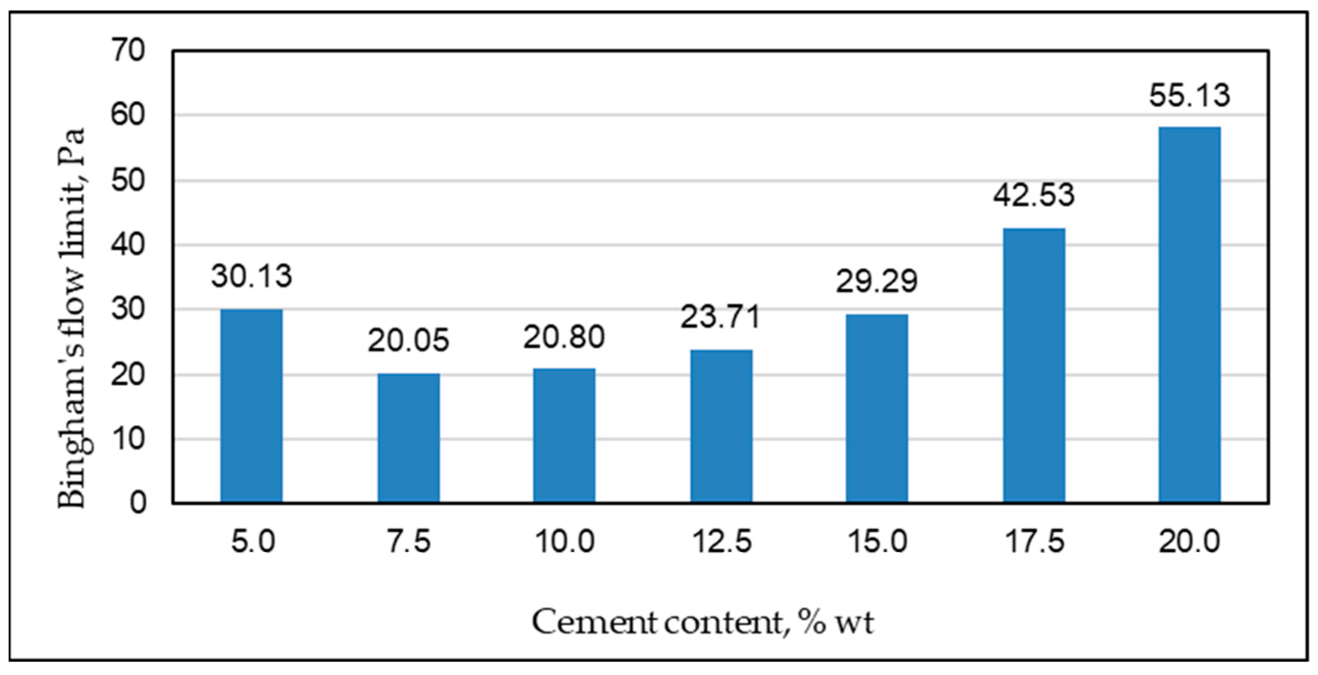
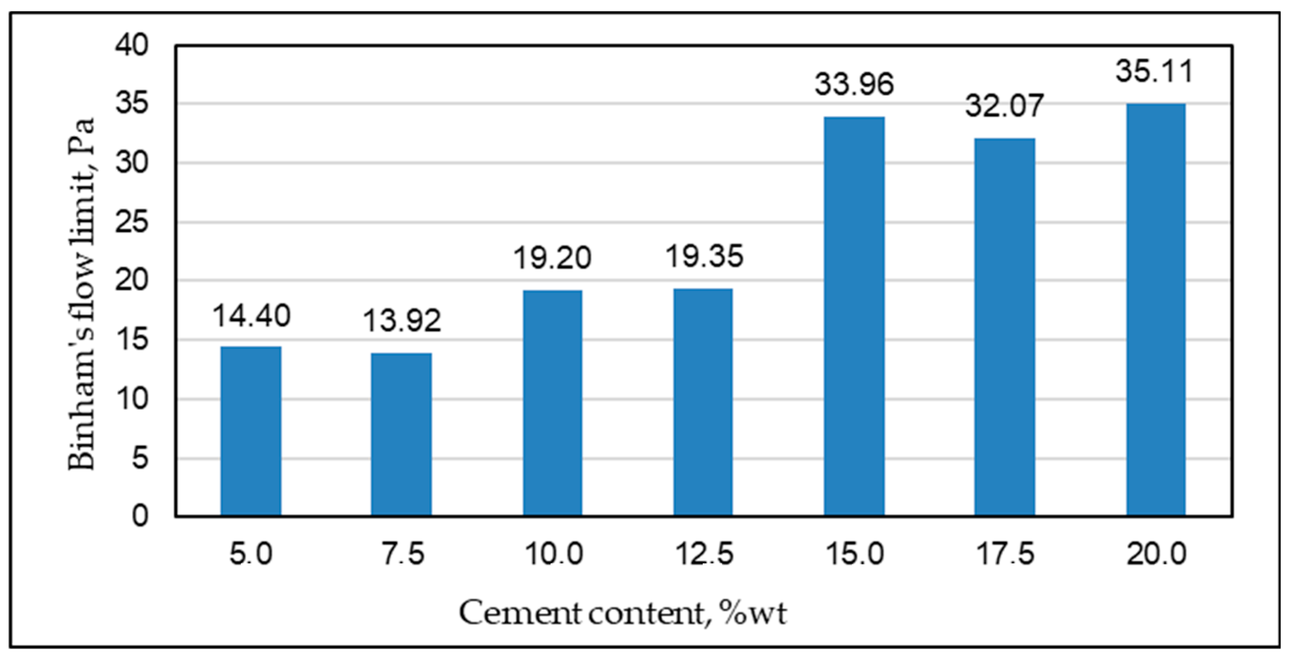
The process of the coagulation–crystalline crosslinking of the clay–cement grout in the second stage and the highest desired strength in the third stage determines the range of variation in the clay and cement content and the selection of appropriate liquefiers. The internal structure of sealing slurries is a three-dimensional network with measurable mechanical strength (i.e., stiffness). In the case of clay slurries, the occurrence of this phenomenon is attributed to the free orientation of the dispersed grains and the formation of very weak hydrogen bonds between them. The structure formed resembles that of a gel, which can be destroyed by small movements. The rate of the structure’s decay depends on the number of bonds that are destroyed, while the rate of structure reconstruction increases as the number of bonds formed increases. At a certain point, a state of dynamic equilibrium is reached in which the rate of structure reconstruction is equal to the rate of bond decay. Figure 4 and Figure 5 show the changes in the flow boundaries as a function of the cement addition for kaolinite- and smectite-type clay-based binders [49,50].
Clay–cement slurries are a special case of a system in which the reversible processes associated with the thixotropic behavior of clay minerals are overlaid with the irreversible physical and chemical processes that accompany the cement hydration process. These processes, which consist of changes in the composition of the solution and the formation of solid reaction products, have a significant impact on the rheology of clay–cement slurries. The process of cement hydration is a complex reaction during which there is an overlap of influences, reacting with water to form Portland clinker. The process is a multistage one, and the individual clinker phases maintain their own specific reaction rates [51,52,53,54,55]. Figure 6 shows the changes in the viscosity versus the shear rate for a smectite clay-based slurry.
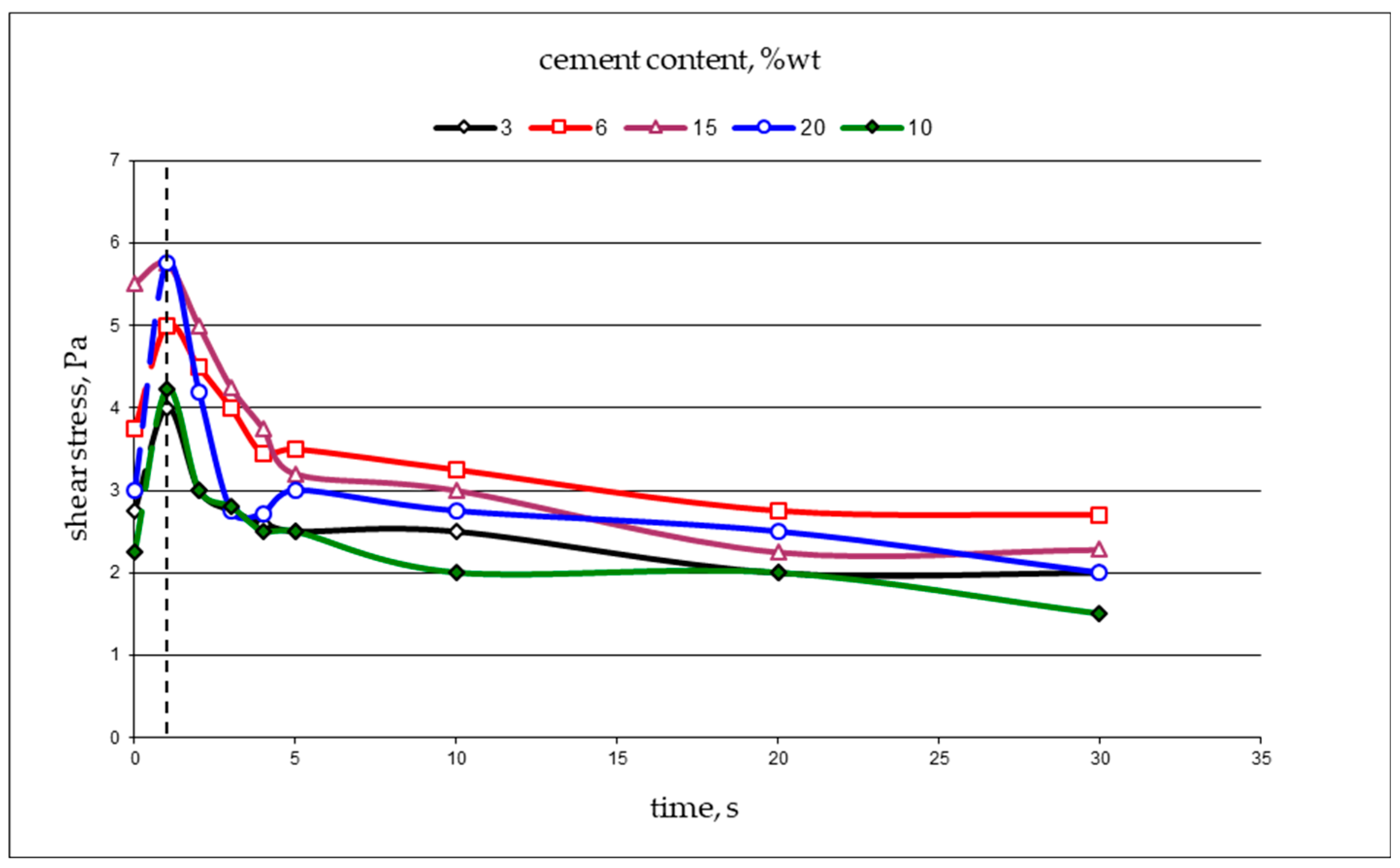
The measurements show a significant increase in the shear stress and apparent viscosity of the slurries as the amount of cement increased. In all cases, the characteristic inflection of the flow curves and the maxima of the values in the shear rate range from 5 to 15 s−1 can be seen. The successive increase in the cement share shifted the inflections towards lower shear rate values. For a cement share of 3%, the maximum of the shear stress occurred at a shear rate of approximately 12.5 s−1, while for an addition of 20%, it localized at a shear rate of approximately 8 s−1. At higher shear rates (i.e., >15 s−1), the shear stresses stabilized (i.e., pseudoplastic flow). The maximum shear stress at the shear rate condition (>0) was measured on specimens that remained at rest for 10 min after the internal structure was completely destroyed. The tests were performed on a smectite clay base (Figure 7).
Studies have shown that the internal structure in resting slurries is formed very quickly and is linked to the hydration reaction. An irreversible spatial network is formed 10 min after the slurry is prepared. Its destruction during shearing occurs in one second; depending on the increase in the cement content, the stiffness of the pseudo-thixotropic structure gradually increases. Dashed line indicates maximum stiffness of thixotropic structure

6. Properties of Hardened Slurry

6.1. Filtration Properties

The filtration coefficient was proposed by French researcher H. Darcy, who was the first to address the phenomenon of filtration. Based on experiments on sand samples, he found that the volumetric filtration flow rate (Q) is proportional to the hydraulic gradient (Δh/l), the cross-section (F) through which filtration occurs and the filtration coefficient (k). Based on these observations, he formulated a basic law of filtration, called Darcy’s law, on which the dynamics of groundwater in porous environments is based when the flow is laminar [56,57,58].
Given the above assumptions, the filtration coefficient can be expressed by the formula:
k = Q l Δ h F
The filtration coefficient, which has a rate dimension, depends on both the properties of the filter medium and the physical properties of the filter fluid, such as density, temperature and viscosity. Based on the value of the filtration coefficient and the permeability, the filtration capacity of the sealing slurry can be divided, determining its suitability. The division of rock media according to their permeability is shown in Table 1 [59,60].
The measurements of the filterability showed a very clear effect of changes in the mineral composition of the tested binders on their filtration coefficient (Figure 8). Changes in the amount of the individual components translated into clear differences in the filtration properties. Changes in the proportion of the cement in the range of 3 to 20% changed the filtration coefficient of the binders by four orders of magnitude. For the binders containing 3% cement, the filtration coefficient was 1.47 ± 0.8∙10−7, while at 20% content, it was 4.4 ± 1∙10−11 m/s.

6.2. Binder Strength

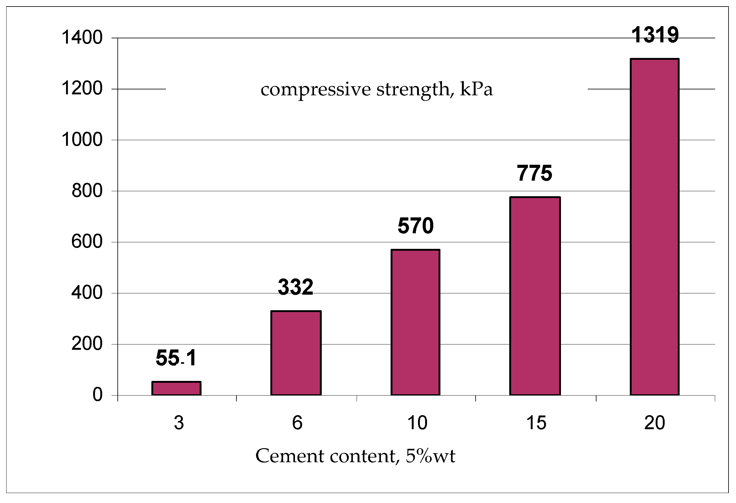
A clear successive increase in the mechanical compressive strength was found with increasing the amount of cement in the binder. The values changed in the range from 55 kPa to 1.3 MPa, with a cement content of 3 to 20%. The most pronounced changes occurred with the samples corresponding to a cement percentage of 3% and 6%. In this case, an increase in the cement share in the binder by 3% exerted an almost six-fold increase in the mechanical strength. The changes in the mechanical strength of the samples as a function of the cement content are shown in Figure 9.
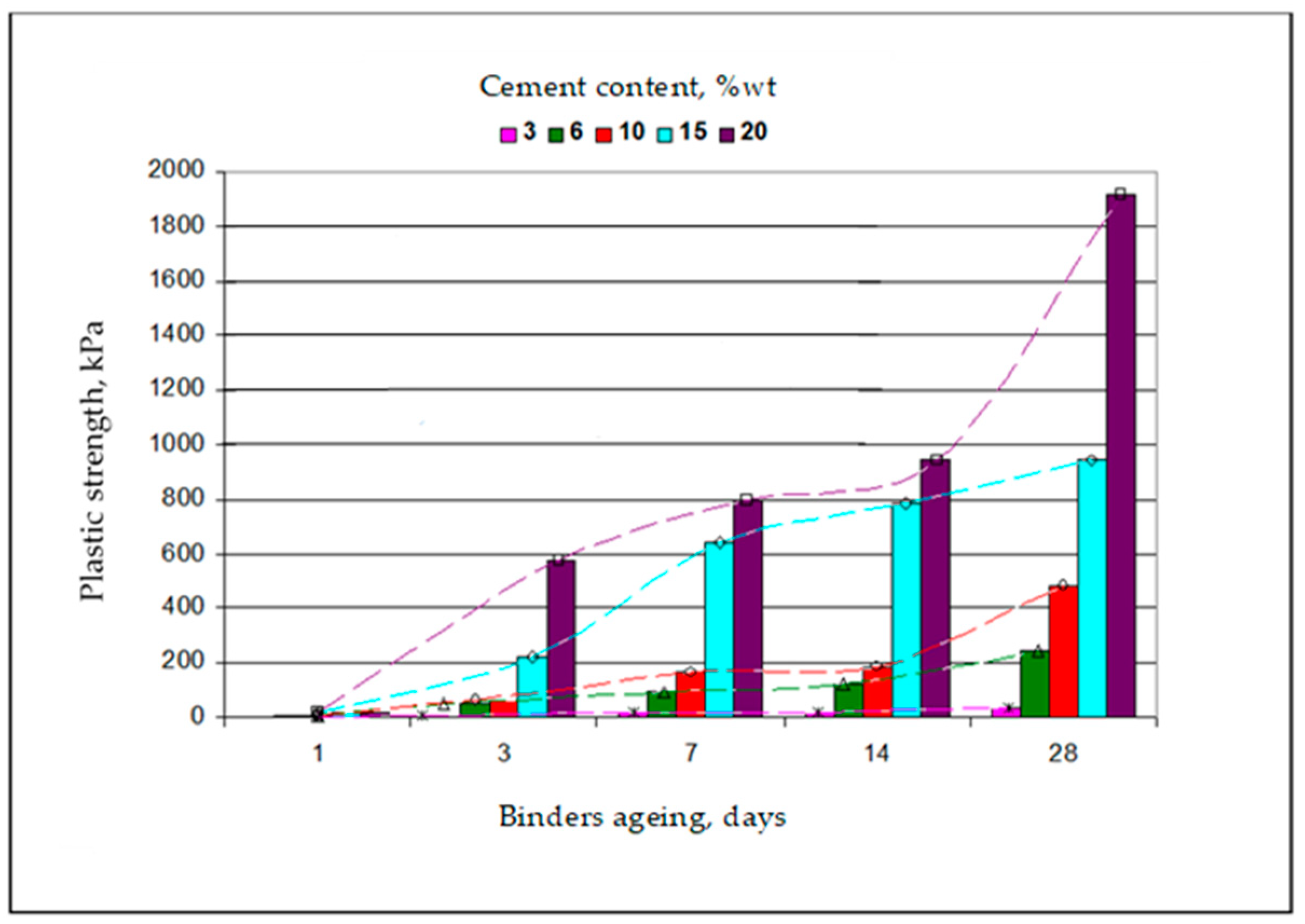
The aging time of the sealing binders successively increased the plastic strength. The kinetics and extent of these changes over time varied, depending on the proportion of and type of individual components. It has been shown that cement significantly increases the plastic strength (80 times), especially in the first three days of maturation if the amount of cement is greater than 15% (Figure 10). With smaller amounts of cement, the increase in the plastic strength (10 times) was smoother and more uniform over the entire range of the maturation studied. The dashed line illustrates the increase in plastic strength.

6.3. Structure of Slurries on a Microscale

The microstructures of the low-vacuum suspensions during the initial stages of setting are shown in Figure 11 and Figure 12 [50]. For all sealing suspensions, the SEM microphotographs confirm the tendency of the suspensions to form agglomerates at the initial stage of hydration, i.e., within an hour of mixing. These agglomerates, visible in the photographs, were easily broken up when conducting the rheological measurements, with the kaolin-based slurry showing the least tendency to agglomerate than the slurries with smectite clay added. Such information is important in terms of assessing the ability of the slurry to inject into and fill voids and cracks in the soil so as to effectively fill, strengthen or seal them.

6.4. Reducing Migration of Pollutants

Ground contamination can be divided into two groups; one includes inorganic contaminants, mainly heavy or amphoteric metals, and the other group consists of organic contaminants, mostly in the form of petroleum substances. One method of limiting their migration is the solidification method which seals the substance into a monolithic solid with high structural integrity. In carrying out this process, a chemical interaction between the solidifying reagents and impurities is not always necessary. Mechanically, the resulting waste is bound into a monolith, thus obtaining a more stable form. The purpose of this treatment is to reduce the mobility of the ground contamination and prevent its migration into the natural environment and, above all, into groundwater. Stabilization is used in technologies that reduce the waste’s hazard potential by converting contaminants into their least mobile or toxic form. Stabilization does not significantly affect the physical nature and characteristics of the waste [61,62]. Previous studies indicate that clay–cement mixtures have very good immobilization properties for metal cations (heavy metals and transition metals) [63,64,65].
Despite effective inhibition, there is a risk that amphoteric metals in a strongly alkaline solution may form compounds that are readily soluble in water. Relationships between highly alkaline clay–cement mixtures and the potential for the release of harmful metal cations into the environment have been observed [66,67,68]. Transition metals produce compounds that exhibit the strongest amphoteric properties. This property is very common for hydroxides of metals of medium electronegativity. The amphoteric property of a compound is related to the ability of each element to form anions and cations in aqueous solution. As an example, the chromium ion, Cr3+, in strongly acidic solution forms a salt, CrCl3 (in the presence of an abundance of chloride ions, it forms a complex ion). In weakly acidic and neutral solutions, the chromium ion precipitates in the form of a slightly soluble hydroxide, Cr(OH)3. In this form, chromium hydroxide in alkaline solution dissolves to form chromium ions [Cr(OH)4] and tends to migrate into the environment [18,69,70,71]. A characteristic feature of clay–cement binders is that they behave like viscoplastic liquids throughout the bonding area and do not form a rigid crystalline structure characteristic of concrete, for example. As a result, the combination of the linking phases contained in the material and the finely dispersed clay fractions provides high tightness and retention capacity.
In the structure of clay cement mixtures, there are three possibilities for the immobilization of ions:
-
Interlayer position in clays;
-
Intermolecular bonds in cement;
-
Formation of other structures.
In light of these facts, a fundamental understanding of the chemistry of clay–cement mixtures remains an important issue. Ion exchange in clays depends on the crystal structure of the mineral and the chemical composition of the solution in contact with the mineral. Ion exchange in these minerals is a reversible chemical reaction that occurs between ions near the mineral surface by unbalanced electrical charges in the mineral structure and ions in the solution in contact with the mineral. Generally, the excess charge on the mineral is negative, and it attracts cations from the solution to neutralize this charge. Chemical reactions in ion exchange follow the law of mass action, but the reactions are limited by the number of exchange sites on the mineral and by the binding strength of the exchange cations to the mineral surface [72,73]. Each clay mineral has a range of exchangeable capacities due to the differences in the structure and chemical composition. These ranges (in milliequivalents per 100 g) are for kaolinite 10–40 and for smectite 100–150 [74,75]. The available interlayer space contains exchangeable cations and water molecules. With the introduction of different types of cations, the interpacket space becomes inaccessible and the cations nonexchangeable. In the position of exchangeable cations, zinc, lead or chromium can be substituted, with small cations with a high charge being favored due to the fact of their charge and ionic radius [76,77,78].
The second possibility through ion immobilization is intermolecular bonds in the cement. The samples were mixed before the hydration process, so the phenomenon of ion retention was considered with the nonhydrated phases. Of course, after mixing with water and solidifying the samples, the clinker phases transformed into CSH gels, and the actual immobilization already occurred in the hydrated minerals. Several clinker phases could be identified, such as C3S allite, C2S belite, C4AF brownmillerite and C3A tricalcium aluminate. In the cement clinker, allite was the dominant fraction (65%). The structure of allite is very interesting—tricalcium silicate, C3S, has a structure with isolated [SiO4], which are connected by polyhedral Ca-O. The approximate chemical formula is 3CaO-SiO2, but in reality, the structure is different—allite shows complex polymorphism depending on the impurities. Pure allite has a monoclinic structure, while the allite found in clinker is a solid solution with a very defective structure. Oxygen atoms occur in two different coordination—in Si thetraedres and in Ca-octaedres coordinated by sic calcium ions. Because of this, cations can be substituted in the structure during the hydration process [79]. The effect of individual ions on the structure of C3S has been widely studied in recent decades [80]. A higher symmetry of the crystal is achieved without substituent ions by defining a quantity called the structure differentiation factor, D, in which structural parameters, such as the radius, electronegativity and the coordination number of the substituent ion with respect to Ca2+, are considered. Table 2 shows the relationship between the chemical structure parameters of Pb2+, Zn2+ and Cr3+ ions and their substituents and the ability to destabilize alite crystals. An absolute value of the D factor greater than or equal to 0.2 destabilized the structure. The conclusion is that the structure of allite immobilizes amphoteric metals, but lead can be dangerous to the stable structure.
D = Z · Δ x · R Ca 2 + R R Ca 2 +
D—Structure different factor—related to calcium.
In the following formula:
  • Z—Ion charge:
  • Δx—Electronegativity difference between ions and calcium;
  • R—Ion radius;
  • RCa2+—Calcium cation radius.
Table 2. Parameters of ions with substitution pattern.
Pb2+Zn2+Cr3+
Ionic radius (pm)1327464
Coordination number446
Electronegativity1.871.651.66
Substitution patternPb→CaZn→CaCr→Ca/Al
D factor−1.320.3280,7
A third mechanism for ion retention in clay–cement materials is the formation of insoluble silicate phases. Stempkowska [15] conducted an experiment to confirm the possibility of the precipitation of some amphoteric metal cations in the form of insoluble and stable salts in a strong alkaline solution. Sodium silicate was added to each solution of soluble salts of the selected metal cations to observe whether a precipitate would form. The experiment was conducted under the following conditions:
-
Concentration of 20% of the following salts: PbNO3, ZnCl2 and CrCl3;
-
Sodium silicate Mk = 2.5;
-
Reagents in the ratio of 1:1.
To accelerate the rate of the reaction, the samples were placed in a laboratory dryer at 80 degrees Celsius. All samples formed an insoluble precipitate as follows:
-
Lead (II) silicate monohydrate PbO∙SiO2∙H2O (white crystals);
-
Zinc(II) silicate monohydrate ZnO∙SiO2∙H2O (blue gelatinous precipitate);
-
Chromium (III) silicate monohydrate Cr2O3∙SiO2∙H2O (pale green crystals).
Additional validation of the formation of the insoluble chemical compounds was obtained from the SEM images with EDS analysis (Figure 13). The micro-area from which the analyses were performed is marked with the numbers 1 and 2. The EDS analysis showed that the content of the transition metals significantly increased, while the content of the polluting elements (Zn, Cr and Pb) decreased. These metals were immobilized in the cement phases (long, fine crystals).
The environmental contamination by petroleum substances is one of the most important environmental problems. The penetration of inadequately treated refinery and petrochemical wastewater into land, open water bodies or farmland, as well as accidents involving petroleum products, can cause serious consequences due to the highly toxic and carcinogenic nature of these substances. There are opportunities to use clay–cement binders to reduce the migration of organic pollutants from heavily contaminated land. Stempkowska et al. [18,21] conducted studies on the immobilization of petroleum substances in clay–cement binders. The content of the bentonite-type clay in the samples was 40–80%, with a cement content of 10 to 20% (Table 3). The rest of the material was soil contaminated with oil substances. For example, the distinction 40/10 means that the mixture contained 40% clay and 10% cement, and the rest was contaminated soil. It was proven that approximately 80% of aliphatic hydrocarbons remain in the binders and approximately 20% are washed away. However, their content is always less than that allowed by the regulation of the “Minister of Environment: On Soil Quality Standards and Earth Quality Standards” (Journal of Laws, 02.165.1359), which is 15 mg/kg. The content of aromatic hydrocarbons in the filtrates was less than the detection limit. The accumulation capacity of the binder in all cases was very high. There were no risks caused by the possible migration of aromatic hydrocarbons into groundwater and soils. The migration of contaminants strongly depends on the filtration coefficient and the initial concentrations of the substances tested. Under extremely unfavorable conditions, the spread of the analyzed pollutants could reach up to 6 m in a year.

7. Low-Energy Injection Methods

The use of clay–cement binders as water-flow-restricting elements in hydrological and hydraulic engineering structures requires the use of appropriate methods. Injection methods are particularly recommended, because they require lower energy inputs than traditional excavation. Using injection methods, the substrate is strengthened quickly and noninvasively. The advantages of these methods include:
-
Fast working time of a few days, not months;
-
No need to lay out specialized working platforms;
-
No damage or changes in the soil bearing capacity caused by excavation [45,81,82,83].
Depending on the needs, it becomes necessary to make a continuous antifilter curtain or only to fill the gaps created during the operation of the structure. Each of the following technologies, in simple terms, consists of injecting a suitable grout into the soil to improve its properties. In the case of the construction of an impermeable antifiltration barrier, clay–cement binders can be injected into the soil using the vibration-injected slit barrier method or deep soil mixing. In cases where the binder is only used to fill existing cracks and fissures in the structure, a low-pressure injection method can be used.

7.1. Vibration-Injected Slit Barrier Method

This method involves the construction of a slotted aperture, using the I-beam sinking method, through a vibratory hammer suspended from the mast of a self-propelled piling rig (Figure 14). The hydraulic vibro hammer is driven into the body of the shaft with the assistance of vibration and pressure from a machine moving along the crown of the shaft. The penetration to the target depth is carried out from a preprepared technological trench in the axis of the screen (approximately 40 cm wide and 40 cm deep), which during injection is filled with the surplus sealant used to make the screen. As the I-profile is pulled upward, the free space is filled with a sealing material that also penetrates into the pore space of the surrounding soil.
The machine moves along the axis of the screen, making individual parts so that the next one hooks into the one already made. This is because the continuity of the shutter must be maintained. A column of I-beam profile has a width of 0.5–0.8 m. The pumping of slurry into the resulting gap is carried out through nozzles at a pressure of 0.8–1.5 MPa. The barrier after hardening is characterized by a thickness of 8 to 23 cm.

7.2. Deep Soil Mixing Method

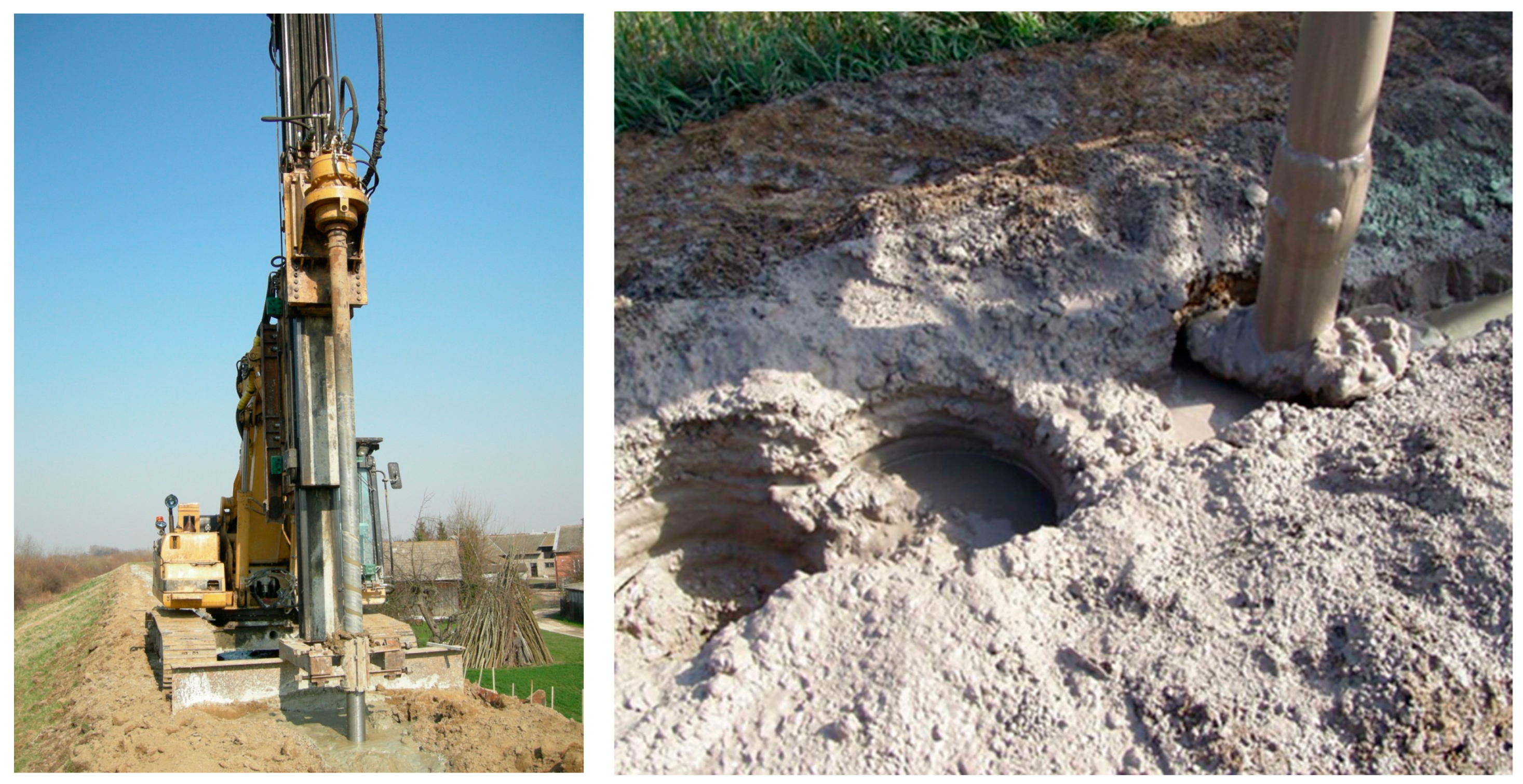
The construction of an antifiltration screen by the method of deep soil mixing involves drilling overlapping columns in the axis of the embankment, carried out with the help of a specialized drilling rig and an stirrer, which mixes the supplied clay–cement binder with the soil, located on the shaft (Figure 15). The stirrer, in the form of a spiral drilling tip, with a special shape is screwed into the soil.
Plunging the drill is combined with feeding the finished binder. After reaching the target depth, this is the actual plunge-mixing phase, which involves feeding the binder and pulling the mixer upward. Mixer speeds and pull-up rates are selected according to the type of soil. Usually, it is approximately 60 revolutions per minute, and 2–3 mixing cycles are performed. After the entire column is completed, additional mixing is performed in the vertical direction by rapidly plunging and pulling up the mixer. First, in the axis of the waterproofing screen, the columns of the first series are built, spaced from each other so that the columns of the second or subsequent series, when completed, overlap with them and with each other. The binder is fed through nozzles located in the bottom of the drill; the feeding pressures are 0.8–1.5 MPa.

7.3. Low-Pressure Injection Method

Low-pressure injection involves pressing the binder through a predrilled hole (Figure 16). Under the influence of the applied pressure, existing voids or cracks are penetrated by the fresh grout, with the result that it is possible to seal a section of an embankment or other structure without the need for a continuous barrier. At the same time, the penetrating binder pushes the soil in the immediate vicinity of the penetrated cavity, which can lead to the strengthening of the areas immediately adjacent to the filled void. An additional advantage of the method in question is that it can be used wherever; for various reasons, it is impossible to make an additional partition. The binder injection pressure is approximately 2–3 bar.

8. Recommendations for the Application of Clay–Cement Binders

The nature of the processes of structure formation and the properties of the structures formed in the clay–cement slurry depend on the proportion of the clay fractions and cement. When developing the optimal formulation, it is necessary to adapt to specific hydrogeological conditions and the type of work. The increase in the proportion of cement improves the filtration properties and significantly increases the mechanical strength. On the other hand, it causes a marked increase in viscosity, which makes it more difficult to pump the clay–cement slurry and degrades its ability to penetrate cracks. It also causes a decrease in the plasticity and an increase in the manufacturing costs. An increase in the proportion of clay minerals significantly reduces the value of the filtration coefficient and causes an increase in the mechanical strength while maintaining the plastic deformability. However, it causes an increase in the viscosity and, thus, also makes the slurry more difficult to pump.
A comparison of the measurements of the filtration coefficients of noncohesive soils, for building the embankment body, with that of the filtration coefficients of the antifiltration barriers showed a significant reduction in their values. Table 4 shows the changes in the filtration coefficient depending on which method was used to make the screen. The sands building the embankment body were characterized by filtration coefficients ranging from 2.9∙10−5 to 6.0∙10−6 m/s. In contrast, the filtration coefficients for the screens ranged from 6.84∙10−8 to 6.00∙10−9 m/s, depending on the injection method. This gave a reduction in the measured parameter of at least two ranges of magnitude.
In conclusion, it should be noted that clay–cement grouts used for reinforcing dikes should meet the following criteria:
-
Rheological properties that allow pumping over long distances;
-
Ability to penetrate cracks and voids;
-
Setting in a relatively short time;
-
Low filterability—filtration coefficient < 1∙10−8 m/s;
-
Mechanical strength > 300 kPa.
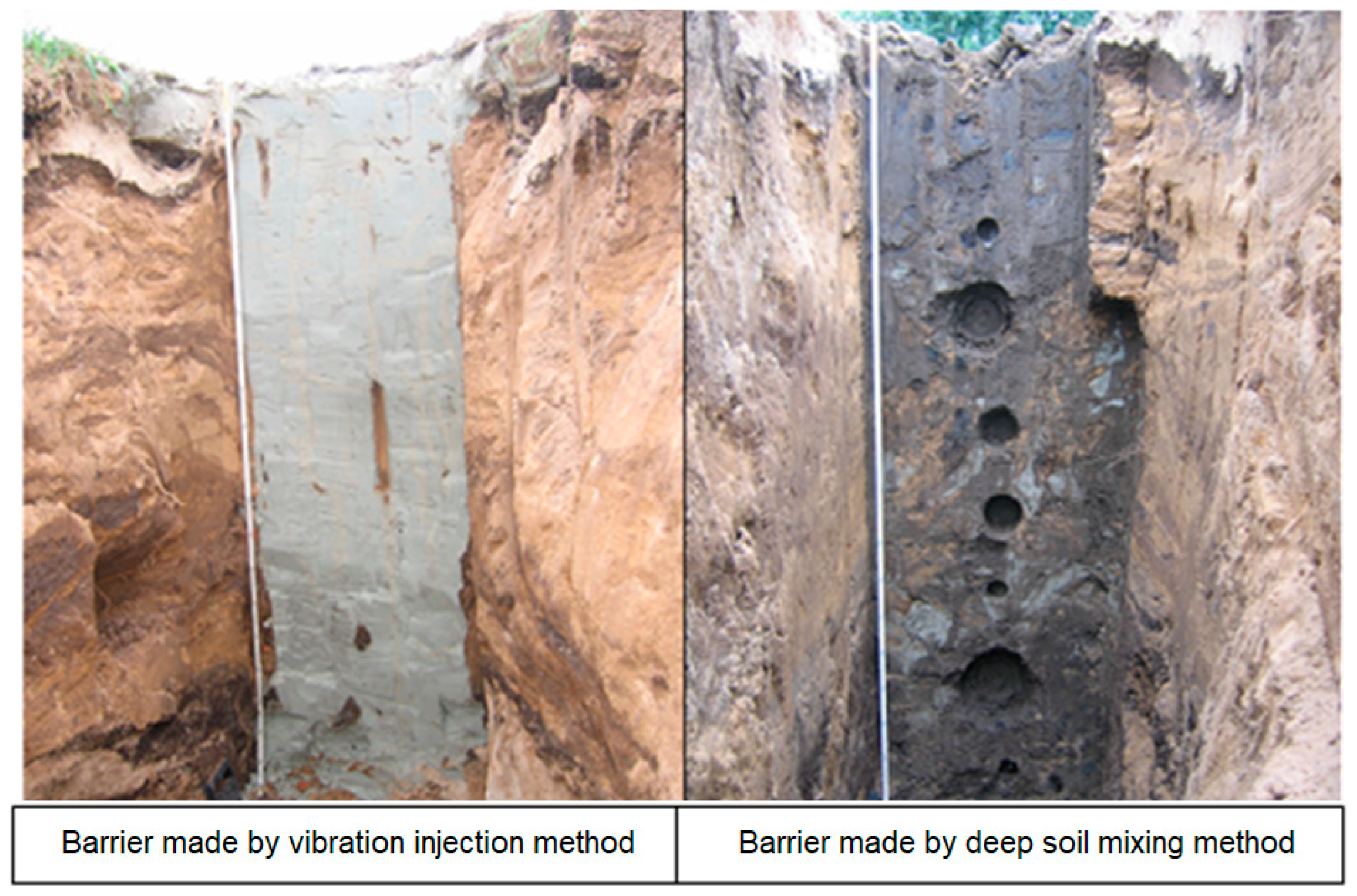
The recipes of clay–cement binders are protected by patent reservations [84,85,86]. Examples of completed barriers are shown in Figure 17.

9. Summary

This review shows that the introduction of clay into cement in the production of insulation barriers results in a sustainable material with promising properties.
Clay–cement sealants are viscoplastic systems. Their characteristic feature is that they behave like plastic bodies practically throughout the entire setting range (1–28 days). As a result, stabilizing binders did not disturb the layout of their surrounding environment. In addition, due to the prolonged initial interval of structure formation, they do not leach out of fractures and karstic underground water joints, and the fine-dispersed clay fractions they contain ensure their high tightness. The formation of the internal structure of binders can be controlled by both the amount of cement and finely dispersed clay minerals and the amount of modifiers of the hydration process. Studies have shown, in agreement with the mechanics of dispersed systems, that bodies with different mechanical strengths and plasticity can interpenetrate each other, in the original liquid environment, by two fundamentally different routes: condensed or crystalline crosslinking or reversible internal structures.
Measurements of the viscoelastic properties of clay–cement suspensions are useful for evaluating their application properties as well as providing new insight into the elucidation of cement hydration kinetics. They make it possible to estimate whether the initial stage (i.e., immediately after mixing the clay–cement slurry) is dominated by reversible processes (related to the presence of clay minerals) or irreversible processes (related to the cement hydration reaction taking place).
A distinguishing feature of the tested clay–cement binders is the reduction of water infiltration. The filtration coefficient of these materials is below the value of 1∙10−8 m/s, as a result, they can be treated as impermeable barriers. This property, combined with a not very high mechanical strength (uniaxial compressive strength of 0.5 to 1.5 MPa), qualifies them for use wherever the main factor determining the suitability of the grout is waterproofing and susceptibility to deformation.
An important feature of clay–cement binders is their ability to limit the migration of contaminants. After the hydration process, these mixtures form flexible and impermeable structures, which can be used as barriers that immobilize the spread of contaminants. Tests have shown that in the case of amphoteric metals, almost 100% accumulation of contaminants in the structure of clay–cement slurries is possible. In the case of impurities of organic origin, approximately 80% of the total aliphatic hydrocarbons remain in the binders and approximately 20% are washed away. The content of aromatic hydrocarbons in the filtrates is below the detection limit.

Author Contributions

Conceptualization, Ł.W. and A.S.; methodology, A.S.; validation, K.A.O., A.S., T.G. and Ł.W.; formal analysis, Ł.W.; investigation, Ł.W. and A.S.; resources, A.S.; data curation, Ł.W.; writing—original draft preparation, A.S.; writing—review and editing, T.G.; visualization, T.G., A.S. and K.A.O.; supervision, T.G. All authors have read and agreed to the published version of the manuscript.

Funding

This research received no external funding.

Data Availability Statement

Not applicable.

Conflicts of Interest

The authors declare no conflict of interest.

References

  1. Głąb, W.; Jawański, W.; Thiel, K. Badania nad Uszczelnianiem Podłoża Zapory Wodnej Zaczynami Cementowo-Iłowymi; IOMB: Warsaw, Poland, 1965; Volume 524. [Google Scholar]
  2. Wójcik, Ł.; Izak, P.; Mastalska-Popławska, J.; Gajek, M. Clay-cement suspensions-rheological and functional properties. J. Physics. Conf. Ser. 2017, 790, 1–7. [Google Scholar] [CrossRef]
  3. Michette, M.; Lorenz, R.; Ziegert, C. Clay barriers for protecting historic buildings from ground moisture intrusion. Herit. Sci. 2017, 5, 31. [Google Scholar] [CrossRef] [Green Version]
  4. Mousavi, S.S.; Bhojaraju, C.; Ouellet-Plamondon, C. Clay as a Sustainable Binder for Concrete—A Review. Constr. Mater. 2021, 1, 134–168. [Google Scholar] [CrossRef]
  5. Więcław, E.; Koda, E. Model przepływu wód podziemnych i transportu zanieczyszczeń dla składowiska z bentonitową przesłoną pionową. Przegląd Geol. 2005, 53, 770–775. [Google Scholar]
  6. Kouakou, C.; Morel, J.-C. Strength and elasto-plastic properties of non-industrial building materials manufactured with clay as anatural binder. Appl. Clay Sci. 2009, 44, 27–34. [Google Scholar] [CrossRef]
  7. Hanafi, M.; Ekinci, A.; Aydin, E. Engineering and Microstructural Properties of Alluvium Clay Stabilized with Portland Cement and Coal Bottom Ash for Sustainable Future. KSCE J. Civ. Eng. 2022, 26, 5049–5066. [Google Scholar] [CrossRef]
  8. Kumar, R.A.; Goyal, S.; Srivastava, A. A comprehensive study on the influence of supplementary cementitious materials on physico-mechanical, microstructural and durability properties of low carbon cement composites. Powder Technol. 2021, 394, 645–668. [Google Scholar] [CrossRef]
  9. García Calvo, J.L.; Pedrosa, F.; Carballosa, P.; Revuelta, D. Evaluation of the sealing effectiveness of expansive cement grouts through a novel water penetration test. Constr. Build. Mater. 2020, 251, 118974. [Google Scholar] [CrossRef]
  10. Słowikowski, D.; Kacprzak, G. Implementation of low pressure injection for soil reinforcement and sealing-selected application. Tech. Trans. Environ. Eng. 2013, 110, 111–119. [Google Scholar]
  11. Fu, J.; Wang, D.; Li, X.; Wang, Z.; Shang, Z.; Jiang, Z.; Wang, X.; Gao, X. Experimental Study on the Cement-Based Materials Used in Coal Mine Gas Extraction for Hole Sealing. ACS Omega 2021, 3, 21094–21103. [Google Scholar] [CrossRef]
  12. Zhang, J.; Li, B.; Wang, B.; Qu, L.; Liu, Q.; Zhu, D. Preparation and Performance Investigation of Optimized Cement-Based Sealing Materials Based on the Response Surface Methodology. ACS Omega 2022, 12, 25380–25393. [Google Scholar] [CrossRef]
  13. Reeves, G.M.; Sims, I.; Cripps, J.C. Clay Materials Used in Construction; Geological Society: London, UK, 2006. [Google Scholar]
  14. Kamon, M. Suitability assessment of bentonite-soil mixtures as the landfill bottom liner material. J. Soc. Mater. Sci. Japan 2002, 51, 36–41. [Google Scholar] [CrossRef]
  15. Stempkowska, A. The trial of immobilization amphoteric metals cations in clay-cement hydroisolation barriers. IOP Conf. Ser.: Mater. Sci. Eng 2019, 641, 1–8. [Google Scholar] [CrossRef]
  16. Stempkowska, A. The ability of clay-cement hydraulic binders to accumulate aliphatic and aromatic hydrocarbons. Cem. Wapno Beton Stow. Prod. Cem. I Wapna 2020, 52–60. [Google Scholar]
  17. Stempkowska, A. The mechanism of amphoteric metals cations immobilization into clay-cement mixtures. J. Pol. Miner. Eng. Soc. 2020, 22, 13–21. Available online: http://www.potopk.com.pl/Full_text/2020_v1_full/IM%201-2020-v1-a2.pdf (accessed on 25 January 2020).
  18. Stempkowska, A.; Wójcik, Ł.; Izak, P.; Staszewska, M.; Mastalska-Popławska, J. Investigation of post-industrial pollutions’ immobilization in a hydraulic self-solidifying clay-cement binder. IOP Conf. Ser.: Mater. Sci. Eng 2018, 427, 1–10. [Google Scholar] [CrossRef] [Green Version]
  19. Borys, M.; Rycharska, J. Parametry zawiesin twardniejących stosowanych do wykonywania przegród przeciwfiltracyjnych w wałach przeciwpowodziowych. Woda-Srodowisko-Obsz. Wiej. 2006, 6, 47–56. (In Polish) [Google Scholar]
  20. Falaciński, P.; Garbulewski, K.; Kledyński, Z.; Skutnik ZCiarkowska, K. Badania barier hydraulicznych z zawiesin cementowo-bentonitowych z dodatkiem popiołów fluidalnych, Przegląd Naukowy. Inżynieria I Kształtowanie Sr. 2004, 2, 202–215. (In Polish) [Google Scholar]
  21. Garzón, E.; Sánchez-Soto, P.; Romero, E. Physical and geotechnical properties of clay phyllites. Appl. Clay Sci. 2010, 48, 3. [Google Scholar] [CrossRef]
  22. Abd El Kader, M.M.; El Deeb, A.S. Preparation and characterization of low-cost waterproofing sheets from NR-loaded clay. HBRC J. 2020, 16, 1–15. [Google Scholar] [CrossRef] [Green Version]
  23. Duan, P.; Shui, Z.; Chen, W.; Shen, C. Effects of metakaolin, silica fume and slag on pore structure, interfacial transition zone and compressive strength of concrete. Constr. Build. Mater. 2013, 44, 1–6. [Google Scholar] [CrossRef]
  24. Cheng, S.; Shui, Z.; Sun, T.; Yu, R.; Zhang, G.; Ding, S. Effects of fly ash, blast furnace slag and metakaolin on mechanical properties and durability of coral sand concrete. Appl. Clay Sci. 2017, 141, 111–117. [Google Scholar] [CrossRef]
  25. Ponraj Sankar, L.; Sivasankar, S.; Shunmugasundaram, M.; Praveen Kumar, A. Investigation on binder and concrete with fine grinded fly ash and silica fume as pozzolanic combined replacement. Mater. Today: Proc. 2020, 27, 1157–1162. [Google Scholar] [CrossRef]
  26. Ponraj Sankar, L.; Aruna, G.; Krishna Rao, A.; Srinivas Kadrekar, K. Studies on drying shrinkage and water permeability of fine fly ash high performance concrete. Mater. Today: Proc. 2021, 46, 930–933. [Google Scholar] [CrossRef]
  27. Guggenheim, S.; Formoso, M.L.; Galan, E.; Bish, D.L. Definition of clay and clay mineral: Joint report of the AIPEA nomenclature and CMS nomenclature committees. Clay Clay Miner. 1995, 43, 255–256. [Google Scholar] [CrossRef]
  28. Bergaya, F.; Lagaly, G. Handbook of Clay Science 2013; Elsevier: Amsterdam, The Netherlands, 2013. [Google Scholar] [CrossRef]
  29. Kumari, N.; Mohan, C. Basics of Clay Minerals and Their Characteristic Properties; Nascimento, G.M.D., Ed.; Clay and Clay Minerals; IntechOpen: London, UK, 2021. [Google Scholar] [CrossRef]
  30. Murray, H.H. Structure and composition of clay minerals and their physical and chemical properties. Applied clay mineralogy-occurrence, processing and applications of Kaoline, Bentonite, Polygorskite-Sepiolite and common clays. Haydn H Murray 2006, 7–31. [Google Scholar] [CrossRef]
  31. Benjamin, K. The Clay Mineral-Structure. 2004. Available online: http://www.groundwaterresearch.com.au/reference_files/hydrology_and_the_clay_minerals/structure.htm (accessed on 23 July 2020).
  32. Andrade, F.A.; Al-Qureshi, H.A.; Hotza, D. Measuring and modeling the plasticity of clays. Mater. Res. 2010, 13. [Google Scholar] [CrossRef]
  33. Andrade, F.A.; Al-Qureshi, H.A.; Hotza, D. Measuring the plasticity of clays: A review. Appl. Clay Sci. 2011, 51, 1–7. [Google Scholar] [CrossRef] [Green Version]
  34. Pusch, R. Environmental Soil Properties and Behaviour, Swelling Clays, Chapter 4; CRC press, Taylor & Francis Group, LLC: Boca Raton, FL, USA, 2012; pp. 133–161. [Google Scholar]
  35. Ren, Y.; Yang, S.; Andersen, K.H.; Yang, Q.; Wang, Y. Thixotropy of soft clay: A review. Eng. Geol. 2021, 287, 106097. [Google Scholar] [CrossRef]
  36. Shahriar, A.R.; Jadid, R. An experimental investigation on the effect of thixotropic aging on primary and secondary compression of reconstituted dredged clays. Appl. Clay Sci. 2018, 162, 524–533. [Google Scholar] [CrossRef]
  37. Kurdowski, W. Cement and Concrete Chemistry; Springer: Berlin/Heidelberg, Germany, 2014. [Google Scholar]
  38. Saleh, H.M.; Eskander, S.B. Innovative Cement-Based Materials for Environmental Protection and Restoration, 2020 New Materials in Civil Engineering; Butterworth-Heinemann: Oxford, UK, 2020; pp. 613–641. [Google Scholar] [CrossRef]
  39. Damineli, B.L.; Pileggi, R.G.; John, V.M. Influence of packing and dispersion of particles on the cement content of concretes. Struct. Mater. J. 2017, 10. [Google Scholar] [CrossRef] [Green Version]
  40. Li, D.; Li, X.; Hu, Y.; Zhang, S.; Mei, C.; Wu, H.; Sun, X.; Fu, Y. Study on Dispersion of Cement Grout in Sand considering Filtration Effect through the EDTA Titration Test. Geofluids 2020, 2020, 6620979. [Google Scholar] [CrossRef]
  41. Mehairi, A.G.; Husein, M.M. Enhancement of cement properties by means of in situ grown nanoparticles. Constr. Build. Mater. 2020, 261, 120496. [Google Scholar] [CrossRef]
  42. Onaizi, A.M.; Huseien, G.F.; Lim, N.H.A.S.; Amran, M.; Samadi, M. Effect of nanomaterials inclusion on sustainability of cement-based concretes: A comprehensive review. Constr. Build. Mater. 2021, 306, 124850. [Google Scholar] [CrossRef]
  43. Lea, F.M. The Chemistry of Cement and Concrete; Chemical Publ. Co.: New York, NY, USA, 1971. [Google Scholar]
  44. Gartner, E.; Maruyama, I.; Chen, J. A new model for the C-S-H phase formed during the hydration of Portland cements. Cem. Concr. Res. 2017, 97, 95–106. [Google Scholar] [CrossRef]
  45. Duque-Redondo, E.; Bonnau, P.A.; Manzano, H. A comprehensive review of C-S-H empirical and computational models, their applications, and practical aspects. Cem. Concr. Res. 2022, 156, 106784. [Google Scholar] [CrossRef]
  46. Wójcik, Ł.; Izak, P.; Stempkowska, A. Pseudotiksotropowe właściwości zawiesin iłowo-cementowych—Pseudothixotropic properties of clay-cement slurries. Ceram. Mater. 2011, 6, 278–282. [Google Scholar]
  47. Szwabowski, J. Reologia Mieszanek na Spoiwach Cementowych; Wydawnictwo Politechniki Śląskiej: Gliwice, Poland, 1999. [Google Scholar]
  48. Izak, P. Reologia w Ceramice; Wydawnictwa AGH: Kraków, Poland, 2017. [Google Scholar]
  49. Wójcik, Ł. Reologiczne właściwości zawiesin iłowo-cementowych. Ph.D. Thesis, AGH Kraków: Kraków, Poland, 2010. [Google Scholar]
  50. Litwinek, E. Lepkosprężyste właściwości zawiesin iłowo-cementowych. Ph.D. Thesis, AGH Kraków: Kraków, Poland, 2021. [Google Scholar]
  51. Haha, M.B.; Le Saout, G.; Winnefeld, F.; Lothenbach, B. Influence of activator type on hydration kinetics, hydrate assemblage and microstructural development of alkali activated blast-furnace slags Cem. Concr. Res. 2011, 41, 301–310. [Google Scholar] [CrossRef]
  52. Berodier, E.; Scrivener, K. Understanding the filler effect on the nucleation and growth of C-S-H. J. Am. Ceram. Soc. 2014, 97, 3764–3773. [Google Scholar] [CrossRef]
  53. Bergold, S.T.; Goetz-Neunhoeffer, F.; Neubauer, J. Interaction of silicate and aluminate reaction in a synthetic cement system: Implications for the process of alite hydration. Cem. Concr. Res. 2017, 93, 32–44. [Google Scholar] [CrossRef]
  54. Zunino, F.; Scrivener, K. The influence of sulfate addition on hydration kinetics and C-S-H morphology of C3S and C3S/C3A systems. Cem. Concr. Res. 2022, 160, 106930. [Google Scholar] [CrossRef]
  55. Litwinek-Rozbicka, E.; Izak, O.; Wójcik, Ł.; Mastalska-Popławska, J. Clay-cement suspensions based on Belchatow and Patoka polymineral clays–rheological characteristics. J. Physics. Conf. Ser. 2020, 1527, 1–7. [Google Scholar] [CrossRef]
  56. Darcy, H. Les Fontaines Publiques de la Ville de Dijon; Gallica: Paris, France, 1856. [Google Scholar]
  57. Brylska, E. Modelowanie Filtracji Wód Podziemnych w Rejonach Ujęć Wodnych; Wydawnictwo Geologiczne: Warszawa, Poland, 1972. [Google Scholar]
  58. Dowgiałło, J.; Kleczkowski, A.S.; Maciaszczyk, T.; Różkowski, A. Słownik Hydrogeologiczny; PIG: Warszawa, Poland, 2002. [Google Scholar]
  59. Ferré, T.P.A.; Warrick, A.W. Infiltration. Encycl. Soils Environ. 2005. [Google Scholar] [CrossRef]
  60. Cheremisinoff, N.P. Principles of Hydrogeology, Groundwater Remediation and Treatment Technologies; William Andrew Publishing: Norwich, NY, USA, 1997; pp. 85–126. [Google Scholar] [CrossRef]
  61. Rakowska, J.; Radwan, K.; Ślosorz, Z.; Pietraszak, E.; Łudzik, M.; Suchorab, P. Usuwanie Substancji Ropopochodnych z Dróg i Gruntów; Państwowy Instytut Badawczy: Józefów, Poland, 2012. [Google Scholar]
  62. Cebula, J.; Rajca, M. Oczyszczanie Gleb i Gruntów; Wydawnictwo Politechniki Śląskiej: Gliwice, Poland, 2014. [Google Scholar]
  63. Wuana, R.A.; Okieimen, F.E. Heavy Metals in Contaminated Soils: A Review of Sources, Chemistry. Risks Best Available Strateg. Remediat. SRN Ecol. 2011, 402647. [Google Scholar] [CrossRef] [Green Version]
  64. Andersen, S.; Ødegård, S.; Seip, M.H. Background levels of heavy metals in Polish forest soils. Ecol. Eng. 1994, 3, 245–253. [Google Scholar] [CrossRef]
  65. Seip, H.M.; Pawałowski, L.; Sulliven, T. Environmental degradation dur to heavy metals and acidifying deposition—A Polish-Scandinavian workshop. Ecol. Eng. 1994, 3, 205–206. [Google Scholar] [CrossRef]
  66. Zhang, H.; He, P.J.; Shao, L.M.; Li, X.J. Leaching behavior of heavy metals from municipal solid waste incineration bottom ash and its geochemical modelling. J. Mater. Cycles. Waste Manag. 2008. [CrossRef]
  67. Wang, D.; Liu, D.; Tao, L.; Li, Z. The impact on the effects of leachate concentrates recirculation for different fill age waste. J. Mater. Cycles. Waste Manag. 2017, 19, 1211–1219. [Google Scholar] [CrossRef]
  68. Bashir, M.J.K.; Aziz, H.A.; Yusoff, M.S. New sequential treatment for mature landfill leachate by cationic/anionic and anionic/cationic processes: Optimization and comparative study. J. Hazard Mater. 2011, 186, 92–102. [Google Scholar] [CrossRef]
  69. Lafhaj, Z.; Samara, M.; Agostini, F.; Boucard, L.; Skoczylas, F.; Depelsenaire, G. Polluted river sediments from the North region of France: Treatment with Novosol process and valorization in clay bricks. Constr. Build Mater. 2007, 148, 606–612. [Google Scholar] [CrossRef]
  70. Varshney, S.; Jain, P.; Srivastava, S.J. Application of ameliorated wood pulp to recover Cd(II), Pb(II), and Ni(II) from e-waste. Mater Cycles Waste Manag. 2017, 19, 1446–1456. [Google Scholar] [CrossRef]
  71. Zmijowa, D.; Koliba, M.; Raclavski, K. Human Health Risk Assessment of Heavy Meatls Bound on Particulate Matter. J. Pol. Miner. Eng. Soc. 2018, 1, 93–98. [Google Scholar] [CrossRef]
  72. Whitworth, T.M. Clay minerals: Ion exchange. In Geochemistry; Encyclopedia of Earth Science; Springer: Dordrecht, The Netherlands, 1998. [Google Scholar] [CrossRef]
  73. Zou, Y.C.; Mogg, L.; Clark, N.; Bacaksiz, C.; Milovanovic, S.; Sreepal, V.; Hao, G.P.; Wang, Y.C.; Hopkinson, D.G.; Gorbachev, R.; et al. Ion exchange in atomically thin clays and micas. Nat. Mater. 2021, 20, 1677–1682. [Google Scholar] [CrossRef] [PubMed]
  74. Pardo, L.; Cecilia, J.A.; Lopez-Moreno, C.; Hernandez, V.; Pozo, M.; Bentabol, J.M.; Franco, F. Influence of the Structure and Experimental Surfaces Modifications of 2:1 Clay Minerals on the Adsorption Properties of Methylene Blue. Minerals 2018, 8, 359. [Google Scholar] [CrossRef] [Green Version]
  75. Esaifan, M.; Warr, L.; Grathoff, G.; Meyer, T.; Schafmeister, M.; Kurt, A.; Testrich, H. Synthesis of Hydroxy-Sodalite/Cancrinite Zeolites from Calcite-Bearing Kaolin for the Removal of Heavy Metal Ions in Aqueous Media. Minerals 2019, 9, 484. [Google Scholar] [CrossRef] [Green Version]
  76. Carroll, D. Ion Exchange in clays and other minerals. GSA Bull. 1959, 70, 749–779. [Google Scholar] [CrossRef]
  77. Sparks, D.L. Ion Exchange Processes, Environmental Soil Chemistry, 2nd ed.; Academic Press: Cambridge, MA, USA, 2003; pp. 187–205. [Google Scholar] [CrossRef]
  78. Whittaker, M.L.; Lammers, L.N.; Carrero, S.; Gilbert, B.; Banfield, J.F. Ion exchange selectivity in clay is controlled by nanoscale chemical–mechanical coupling. Earth Atmos. Planet. Sci. 2021, 116, 22052–22057. [Google Scholar] [CrossRef]
  79. Horst, M.L.; Wensheng, Z. Research review of cement clinker chemistry. Cem. Concr. Res. 2015, 78, 24–37. [Google Scholar] [CrossRef]
  80. Zhang, W.; Ren, X.; Ouyang, S. Development on ion substitution effect on the crystal structure and properties of tricalcium silikat. J. Chin. Ceram. Soc. 2011, 39, 1666–1672. [Google Scholar]
  81. Kowacki, M. Przesłony przeciwfiltracyjne Nowoczesne Budownictwo Inżynieryjne. 2015, 6, 68‖72. Available online: http://www.nbi.com.pl/assets/NBI-pdf/2015/6_63_2015/full/nb_63_web.pdf (accessed on 1 December 2015).
  82. Egorova, A.; Rybak, J.; Stefaniuk, D.; Zajączkowski, P. Basic Aspects of Deep Soil Mixing Technology Control. IOP Conf. Ser. Mater. Sci. Eng. 2017, 245, 022019. [Google Scholar] [CrossRef]
  83. Alhamdi, M.K.; Albusoda, B.S. A Review on Deep mixing method for soil improvement. IOP Conf. Ser.: Mater. Sci. Eng. 2021, 1105, 012110. [Google Scholar] [CrossRef]
  84. Kuś, R.; Janik, G.; Izak, P.; Wójcik, Ł.; Słowikowski, D. Hydraulic mixture for placing wastes dangerous to the environment in the waste disposal grounds PL 386030 A1 Granted 2010. Available online: http://patenty.bg.agh.edu.pl/pelneteksty/PL386030A1.pdf (accessed on 30 May 2014).
  85. Izak, P.; Wójcik, Ł.; Gajek, M.; Mastalska-Popławska, J.; Stempkowska, A.; Kuś, R. Hydroinsulating binder for making anti-filtration partitions PL 229788 B1; Granted 9 January 2018. Available online: http://patenty.bg.agh.edu.pl/pelneteksty/PL229788B1.pdf (accessed on 31 August 2018).
  86. Izak, P.; Wójcik, Ł.; Gajek, M.; Mastalska-Popławka, J.; Stempkowska, A.; Litwinek, E.; Kuś, R.; Janik, G.; Kuś, M. Clay-cement binder with increased resistance to excessive loss of moisture PL 238570 B1 Granted 7 June 2021. Available online: http://patenty.bg.agh.edu.pl/pelneteksty/PL238570B1.pdf (accessed on 1 July 2019).
Figure 1. Classification of clay minerals [27,28,29].
Energies 16 00230 g001
Figure 2. Microcalorimetric curve of the cement hydration process.
Energies 16 00230 g002
Figure 3. Structure formation in sealing slurries [47,48].
Energies 16 00230 g003
Figure 4. Values of the Bingham flow limit for suspensions prepared on the basis of smectite-type clay.
Energies 16 00230 g004
Figure 5. Values of the Bingham flow limit for suspensions prepared on the basis of kaolinite-type clay.
Energies 16 00230 g005
Figure 6. Effect of the amount of cement on changes in the apparent viscosity as a function of the shear rate of smectite clay-based slurries.
Energies 16 00230 g006
Figure 7. Stiffness of the pseudo-thixotropic structure of slurries with different cement contents.
Energies 16 00230 g007
Figure 8. Effect of changing the amount of cement on the value of the filtration coefficient of binders.
Energies 16 00230 g008
Figure 9. Effect of changes in the amount of cement on the mechanical strength of binder.
Energies 16 00230 g009
Figure 10. Changes in the plastic strength of specimens with different cement contents with an increasing aging period.
Energies 16 00230 g010
Figure 11. SEM microphotographs of clay–cement slurry prepared on a smectite clay base with 10% cement addition [46].
Energies 16 00230 g011
Figure 12. SEM microphotographs of clay–cement slurry prepared on a kaolinite clay base with 10% cement addition [46].
Energies 16 00230 g012
Figure 13. SEM and EDS analysis of the sample based on smectite clay [17].
Energies 16 00230 g013
Figure 14. Pile driver with visible I-beam profile while making the shutter (by Łukasz Wójcik).
Energies 16 00230 g014
Figure 15. Making a column using the deep soil mixing method (by Łukasz Wójcik).
Energies 16 00230 g015
Figure 16. Low-pressure injection unit (by Łukasz Wójcik).
Energies 16 00230 g016
Figure 17. Excavations with visible waterproofing screens (by Łukasz Wójcik).
Energies 16 00230 g017
Table 1. Classification of rocks according to filtration properties.
PermeabilityFiltration Coefficient (m/s)Rock Examples
Very good>10−3rubble, gravel, coarse-grained and even-grained sands, massive rocks with a very dense network of small gaps
Good10−3–10−4coarse-grained sands, slightly loamy sands, mixed-grained and medium-grained sands, poorly bonded coarse-grained sandstones, massive rocks with a dense network of gaps
Average10−4–10−5fine-grained sands, evenly-grained sands, loess
Low10−5–10−6dusty and clay sands, silt, sandstones, massive rocks with a rare network of fine cracks
Semi-permeable10−6–10−8clays, silt, siltstones, sandy clays
Impermeable<10−8clays, clay shale, hard clay, clay marls, unbroken massive rocks
Table 3. Aliphatic hydrocarbon contents before and after the filtration process.
SampleAliphatic Hydrocarbon Content before Filtration
(mg/kg)
Aliphatic Hydrocarbons Content in the Filtrate
(mg/l)
Accumulation of Impurities in the Binder
(%)
40/1027.78 5.41580.507
40/1528.12 5.18081.579
40/2025.874.67081.948
50/1022.763.16986.076
50/1523.294.47080.911
50/2021.174.90376.840
60/1018.095.01072.305
60/1518.203.69879.681
60/2017.613.47580.607
70/1014.593.32677.203
70/1514.453.32177.017
70/2013.022.15983.417
80/109.912.51474.631
80/159.342.40374.272
80/208.873.93055.693
Table 4. Results of the filtration coefficient tests in the field conditions.
Filtration Coefficient (m/s)Method by which the Screen Was Made
Embankment before
Making the Screen
Embankment after Making the Screen
2.9∙10−5–6.0∙10−66.0·10−10Vibration-injected
4.0·10−8Deep soil mixing
7.5·10−10Low-pressure injection
Disclaimer/Publisher’s Note: The statements, opinions and data contained in all publications are solely those of the individual author(s) and contributor(s) and not of MDPI and/or the editor(s). MDPI and/or the editor(s) disclaim responsibility for any injury to people or property resulting from any ideas, methods, instructions or products referred to in the content.