Abstract
The present paper deals with the evaluation of the unique design of the thermal energy storage unit and its impact on the overall heat exchange efficiency. The proposed thermal energy storage unit consists of a gyroid thermally conductive structure, the voids of which are filled with sodium acetate trihydrate. The presented concept is focused on the use in the field of heavy machinery, where it is possible to accumulate and re-use waste heat from internal combustion engines from the cooling liquid or lubricating products. The evaluation of designs took place through numerical simulations on three models characterized by different levels of the introduction of the gyroid structure into the design. From the design point of view, the gyroid structure was considered as an object produced by additive manufacturing methods from a thermally conductive filament based on a thermoplastic polymer, which enables considerable simplification of production compared to the use of suitable anti-corrosion metals. A comparison of the essential thermophysical parameters in the process of charging and discharging of the proposed thermal energy storage unit quantified a significant increase in the rate of the charging, respectively, of the discharging process, manifested by a rapid increase in the temperature of the sodium acetate trihydrate volume, respectively, of the output temperature of the heat transfer medium that removes the accumulated heat for further use.
1. Introduction
Wider use of renewable energy sources, as well as sources of waste heat, is often prevented by a time discrepancy between the supply of the energy source and the user’s demand [1,2,3]. Apart from the change in consumer behavior, which manifests itself in a change in the time frame of energy-intensive processes, one of the other possibilities is the introduction of thermal energy storage technologies, which to a large extent, can harmonize the possibilities of the source and the needs of the consumer [4]. The possibilities of energy accumulation are defined mainly by the type and amount of output energy of the source as well as by the performance parameters resulting from the nature of the energy consumer. The most often are accumulated thermal and electrical energy [5,6]. Due to the topic of the paper, the following text only focuses on the cases of thermal energy accumulation.
In most cases, thermal energy is accumulated in substances with a high thermal capacity, which accumulates thermal energy through the mechanism of sensible heat [7]. The volume of these storage substances is enclosed in an insulated container, which reduces heat losses and, thus, the loss of accumulated energy to the surrounding environment. The effort to minimize heat losses is limited by the material characteristics of thermal insulation materials (heat transfer coefficient and thermal resistance) or the structural arrangement of heat reservoirs using a vacuum as a thermal insulator, where unwanted thermal bridges are formed in various hydraulic connections.
One of the ways to successfully compensate limited properties of insulating materials is the introduction of the so-called phase change materials (PCM), which are capable of accumulating thermal energy using the latent heat of melting or solidification of a substance [8]. These substances include paraffin, fatty acids, hydrated salts, and metal composites [9]. The advantage of these substances is the ability to store thermal energy at ambient temperature, i.e., the thermal gradient between the storage medium and the surrounding environment is equal to zero, due to which there are no heat losses due to heat transfer [10].
Among the class of heat storage substances based on PCM, sodium acetate trihydrate (SAT) is one of the most interesting due to its chemical stability, non-toxicity, high specific heat capacity in the form of latent heat, and low thermal expansion. From the point of view of dividing SAT into individual states, the key value is the temperature of 58 °C, which represents the point of change of substance between solid and liquid states. The work cycle starts with the first phase, in which the SAT is in discharged solid state and at ambient temperature. When external heat is supplied, the value of internal thermal energy changes, which is at first manifested in a gradual increase in temperature, up to 58 °C; after reaching this temperature, energy is accumulated through latent heat when the increase in the temperature stops, but its state changes from solid to liquid. After the complete transformation of the SAT crystals into a liquid and with the continued increase in the internal thermal energy, the temperature rises again. After the interruption of the heat supply from the external environment, SAT remains in a liquid state and gradually lowers its temperature to the ambient temperature. In such a state, the volume of the substance is ready for the release of accumulated energy, which happens after the initiation and start of crystallization, when the SAT swiftly increases its temperature to 58 °C, and the heat released in the crystallization process represents usable heat.
A wide spectrum of scientific teams is devoted to the issue of the use of PCM. Mellouli et al. [11] focused their work on the use of a thermal energy storage unit using PCM in the work cycle of a solar heating system. Based on a parametric analysis of the thermophysical parameters of the working substances, the authors proposed the optimal PCM parameters for the selected solar system and determined the amount of usable accumulated heat during peak consumption times. Beaupere et al. [12] assessed the effect of the charging and discharging cycle of the thermal energy storage unit on the properties of SAT. Based on the experimental results, the authors found a 10% decrease in the value of latent heat, which results in a gradual reduction in the usable heat capacity of the device. According to the authors, this reduction is mainly caused by the segregation phenomenon, which can be suppressed by regular mixing of SAT between individual charging cycles. Zhou et al. [13], in the published work, evaluated the use of SAT in the field of ceiling heating using two modes of PCM involvement in the process itself, in which they assessed not only thermophysical parameters but also the effect on internal comfort in the heated object. Wang et al. [14] in their work presented a numerical analysis of the fluid parameters of a thermal energy storage unit with PCM. Authors identified flow unevenness, which was subsequently the object of optimization, by proposing three design changes (change in the flow direction of the heat transfer medium, change in the size of the inlet, and the introduction of a porous plate).
The wider use of thermal energy storage units using SAT is prevented by its low thermal conductivity, especially in the solid-state area, in which the essential phases of the operation cycle occur (charging and discharging process) [15,16,17]. According to sources [18,19,20], the thermal conductivity coefficient of SAT in the solid-state region, depending on the specific chemical composition (the content of additives) and concentration, ranges from 0.4 to 0.7 W·m−1·K−1 and is not significantly affected by temperature changes, as is the case liquid phase.
Increasing the thermal-technical properties of SAT, or PCM in general, is the center of interest of a wide range of scientific teams, which approach this issue from different points of view. One of the presented options is a change of chemical composition when additives or nanoparticles are added to the volume of SAT, which creates a homogeneous mixture with higher thermal conductivity. Another way is to add the so-called macro components (granules, capillaries, flakes), increasing the thermal conductivity of such a mixture. The last common group of possibilities is the use of a matrix of thermally conductive material in the form of metal foam, a three-dimensional regular metal grid, or the introduction of triply periodic minimal surfaces, among which it can include the gyroid structure.
Garay Ramirez et al. [21] in their work studied the addition of a polymer blend of carboxymethyl cellulose, silica gel, and silver nanoparticles to SAT in the process of improving the thermal-technical properties, especially the value of the latent heat. Wang et al. [22], as part of the experimental determination of the thermal and technical properties of PCM, worked with the use of an expanded graphite composite, which increased the values of the accumulated thermal energy as well as the rate of heat accumulation, respectively energy release. Myat et al. [15] experimentally evaluated the effect of adding polyethylene glycol to the PCM to make the charging and discharging process more efficient by changing the thermal conductivity of the resulting mixture. The results presented by the authors suggest a 25% reduction in the charging and discharging time. Liu et al. [23], on the other hand, solved the change in the properties of the PCM by adding a porous structure, which, thanks to the creation of a thermal conductive object, improved the thermophysical properties, thanks to which the proposed thermal storage unit achieved more efficient charge/discharge times. Hassan et al. [24] proposed passive cooling of electronic components using PCM enhanced by a mixture of nanoparticles and metallic copper foam with a porosity of 97%. Falcone et al. [25] in their work pointed out the positive effect of adding copper metal foam to paraffin-based PCM, which increased its thermal conductivity from 0.2 W·m−1·K−1 to 7 W·m−1·K−1. Al-Najjar et al. [26] proposed a thermal energy storage unit design that adjusts the total time of the charging phase by introducing a metal foam layer with different configurations in the volume of the PCM. Chen et al. [27] studied the effect of arc-shaped fins in a shell-tube thermal energy storage unit. The introduction of structure into the PCM volume improved thermal uniformity and promoted the melting process. Zhao et al. [28] designed a thermal energy storage unit combining SAT and copper metal foam, on which they experimentally determined the effect of the given structural arrangement.
From the above overview, it follows that the use of PCM or SAT as a thermal storage material brings several advantages as well as challenges that must be reflected in the design of thermal energy storage units. In the presented paper, the volume of SAT is supplemented with a thermally conductive infinitely connected triply periodic minimal surface in the form of a gyroid structure, which is, in many ways, a suitable method of increasing thermal conductivity [29,30,31,32]. The presented paper deals with the evaluation of the unique design of the thermal energy storage unit and its impact on the overall heat exchange efficiency. The proposed thermal energy storage unit consists of a gyroid thermally conductive structure, the voids of which are filled with sodium acetate trihydrate. The presented concept is focused on the use in the field of heavy machinery, where it is possible to accumulate waste heat from internal combustion engines from the cooling liquid or lubricating products and re-use it at a low temperature during the cold start of the device, which will reduce machinery wear and operating costs [33].
The production of the presented gyroid structure from thermally conductive materials represents a complex problem, which is most often solved by casting metals into a foundry mold. This relatively time and financially demanding method can be largely replaced by additive manufacturing (AM) methods, which mainly consist of 3D printing. Here, it is possible to distinguish 3D printing using powdered metals, which, in many respects, do not offer suitable heat-conducting properties or are limited by the accuracy of production [34,35]. Finally, the use of metals is significantly limited due to the corrosive properties of SAT. To increase thermal conductivity, it is not possible to use alloys based on copper or aluminum, which would significantly degrade in an environment with SAT, which would reduce the overall life of the device [36]. From the point of view of the chemical stability of the material, it seems that various types of anti-corrosion steel [37] with the highest possible value of thermal conductivity are the most suitable metal materials. However, manufacturing from anti-corrosion steel requires advanced processing methods and technologies.
The second option for creating a gyroid structure is the use of standard 3D printing with the use of thermally conductive filaments, which in recent years have experienced unprecedented growth and, from the point of view of thermal conductivity, represent a relatively interesting alternative to metals from the group of anti-corrosion steels, whose thermal conductivity values are at the level of 15 W·m−1·K−1. In the presented concept, we therefore consider a combination of a gyroid structure created from a commercially available thermally conductive thermoplastic polymer, which will form as a heat exchange surface in contact with a heat-accumulating substance, i.e., SAT.
The essential research question of the presented paper that results from the literature review can be characterized as the search for an effective, technically, and economically undemanding method of increasing the thermal conductivity of SAT using standard AM procedures. A subsequent, more focused question is the evaluation of the proposed designs and their impact on the process of charging and discharging of the thermal energy storage unit.
The basic motivation of the research is not only the presentation of the technical design but especially the evaluation of the thermophysical characteristics that affect the operation of the thermal energy storage units that utilize the SAT and the gyroid thermally conductive structure made by AM methods.
2. Materials and Methods
The comparison of the thermal energy storage unit concepts was carried out by numerical simulation. The basic idea of the design is based on the principle of creating a heat exchange surface between the flowing heat transfer medium on the one side (e.g., engine coolant, lubricants) and, on the other side, SAT as a heat-accumulative substance. The essential feature of the design is, therefore, the gyroid structure, i.e., infinitely connected triply periodic minimal surface, the geometry of which can be written trigonometrically using Equation (1) [38].
sin x cos y + sin y cos z + sin z cos x = 0
The modeling of the gyroid structure was carried out in the Solidworks 2017 CAD software environment and consisted of a subsequent series of operations based on the creation of a basic three-dimensional surface characterized by a sinusoidal curve (see Figure 1). The parameters of the curve were defined by the size of the resulting building cell. By copying and rotating, building cells were created with more complex shapes, which eventually completed an object with the dimensions of 40 × 40 × 80 mm, to which the function defining the thickness was applied. This process created a three-dimensional solid body with a thickness of 2 mm, as shown in Figure 1. From the point of view of fluid characteristics, an important parameter is the definition of the characteristic diameter of the channel, which is, in this case, defined by the area with the minimum diameter of the channel and, for the presented model, represented a value of 3 mm.
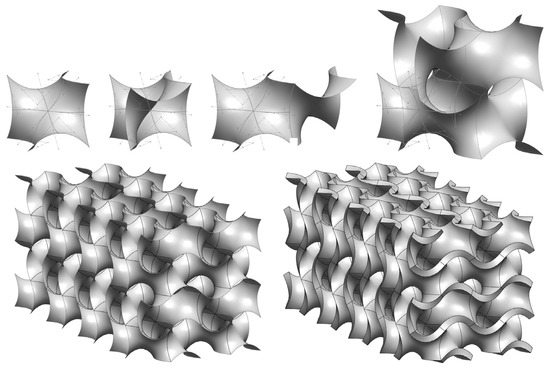
Figure 1.
Individual steps of creating a gyroid structure from the basic surface to the resulting object with dimensions of 40 × 40 × 80 mm, with a wall thickness of 2 mm.
The quantification of the design concepts of the proposed thermal energy storage unit was carried out using three models that reflected different possibilities of including the gyroid structure in the design itself. The highest level is the inclusion of the gyroid structure in the flowing heat transfer medium and also in the SAT volume (concept no. 1); the intermediate level represents the inclusion of the gyroid structure only in the part with the SAT (concept no. 2). For comparison, we also created a model where the gyroid structure is absent, and the heat exchange surface between the flowing medium and the heat-accumulating substance is formed only by a plane wall (concept no. 3). The dimensions of the created models were based on the gyroid structure described above, the size of which was limited by the possibilities of computing power. However, despite the dimensional limits, it is possible to claim that the chosen models represented the concept of the structural arrangement and, therefore, that the transfer of the concept to real dimensions will bring the same mutual evaluation of the concepts. The used models, as well as the boundary conditions of the numerical analysis, are shown in Figure 2.
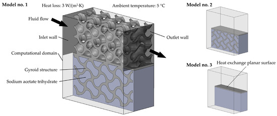
Figure 2.
Used models representing three concepts of the structural arrangement of the thermal energy storage unit based on SAT.
The composition of the models consists of bodies representing the heat exchange surface and bodies representing SAT. The essential parameters of these elements are summarized in Table 1. For the body representing the heat exchange surface, the thermophysical properties were based on a commercially available thermoplastic polymer with the coefficient of thermal conductivity 6 W·m−1·K−1 and the properties of the bodies representing thermal energy storage volume were defined based on SAT with precisely given chemical composition (CH3COONa·3H2O).

Table 1.
Summary of thermophysical properties of gyroid structure and SAT volume in numerical analysis.
The boundary conditions of the simulations (temperatures, volumetric flow of the heat transfer medium, etc.) represented the expected operating parameters of the proposed concept transferred to a reduced scale. In the process of the evaluation of the proposed concepts, two basic scenarios were considered, which describe the key areas of the SAT operation diagram that are most affected by its low thermal conductivity. The first scenario was focused on the charging phase, which is defined by the gradual increase in the SAT temperature up to 58 °C. As a heat source, we used a heat transfer media (water) with a flow rate of 10 L/h and a temperature of 95 °C. The second scenario was focused on the evaluation of discharge, i.e., the transfer of accumulated heat to a heat transfer medium (water) with a flow rate of 10 L/h and a temperature of 5 °C, which simulated the working fluids of an internal combustion engine during a cold start.
The key parameter affecting the results of the simulation of the second scenario was the correct definition of the temperature change during SAT discharge.
The temperature change of the SAT during the release of accumulated energy was mapped using 150 g of SAT, which corresponds to the volume and density of the object that represented the SAT in individual numerical simulations. During the described measurement, the SAT volume was placed in a measuring glass vessel and was initially in a liquid state. The measuring container was placed in the holder so that the entire surface was in contact with the ambient air at a temperature of 5 °C (see Figure 3). The temperature probe measuring the SAT temperature was placed in the center of its volume. Initiation of heat release was performed by supplying the SAT crystal, resulting in the immediate initiation of crystallization, releasing the accumulated heat, and thereby increasing the temperature of the SAT.
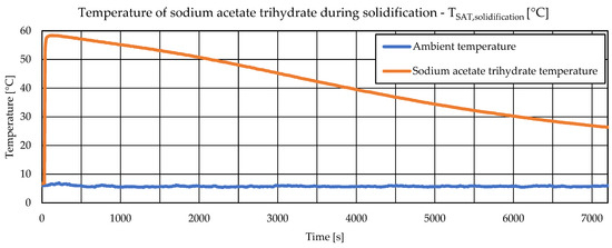
Figure 3.
Temperature change of sodium acetate trihydrate during discharge phase and temperature of ambient environment.
Temperatures were recorded for 7200 s with a measurement step of 3 s via a measuring apparatus consisting of a series of KIMO TTKE-363 thermocouples (type K, range −40 °C to +400 °C), which recorded the temperature of the SAT and the ambient temperature. Thermocouple data were recorded by the KIMO AMI 300 data acquisition system with a thermocouple module with an uncertainty of ±0.8 °C. Numerical simulations were performed using the Solidworks Flow Simulation software through a transient study with a duration of 7200 s and a step of recording the results of 5 s. The presented numerical study was carried out using commercially available software that offers a balanced combination of CAD and simulation tools. During the numerical study, we did not use user-defined functions or any separate code modifying the solution methods.
Due to the low volumetric flow rate of the heat transfer medium, the k-ε viscosity model was used. Thermal properties were calculated with the use of models of heat transfer by convection and conduction, while heat transfer by radiation was neglected. The influence of the external environment was simulated by heat transfer from the external wall with a value of 5 W·m−1·K−1 at an ambient temperature of 5 °C. The solution scheme works on the finite volume method principle, and the convergence conditions were defined at the level of 10−6. The governing equation of numerical analysis is summarized in Equations (2)–(6) [39]. In the fluid regions, SOLIDWORKS Flow Simulation solves the Navier–Stokes equations, which are formulations of mass, momentum, and energy conservation laws:
where u is fluid velocity, ρ is density, Si is the mass-distributed external force (gravity or forces of rotation), H = h + u2/2, h is enthalpy, QH is the heat source per unit volume, τij is viscous stress tensor, is Reynolds viscous stress tensor, and qi is diffusive heat flux. Indices indicate the summation in three coordinate directions. Heat transfer in solids and fluids with energy exchange between them (conjugate heat transfer) is an essential and implicit element of CAD-embedded CFD software. The phenomenon of heat conduction in solid media is described by the following equation:
where e is the specific internal energy, QH is specific heat release (or absorption) rate per unit volume, and λi are the eigenvalues of the thermal conductivity tensor. A more detailed description can be found in the supplied technical documentation [39].
The model of the heat accumulation unit was transformed into a computational mesh for simulation purposes. The Solidworks Flow Simulations software uses a unique mesh-creating methodology, which consists of using immersed-body mesh. With this approach, the creation of a mesh begins independently of the geometry itself, and each mesh cell can arbitrarily intersect the boundary between solid and liquid. This allows the use of Cartesian-based mesh. Such a mesh can be defined as a set of cuboids (rectangular cells) that are adjacent to each other and to the outer boundary of the computational space and, at the same time, are oriented along with Cartesian coordinates. These cells can be divided into solid cells, fluid cells, and partial cells (cells intersecting the immersed boundary). On partial cells, which intersect the surface separating the solid and fluid region is then applied the two-scale wall function, which consists of two methods for thin boundary layer treatment or thick boundary layer treatment. This approach at the fluid/solid interface allows the solution of Navier–Stokes equations in these defined volumes. A complete mathematical apparatus for grid formation methods is provided in the available technical documentation of the software [40].
The effort to minimize the necessary computing time can, under certain circumstances, lead to an error in the result, which is based on an oversimplification of the computational mesh. This unfavorable factor can be, to some extent, minimized by the grid-independent study. In the presented work, a grid-independent study was conducted as a steady state study with parameters of charging phase, when the average temperature of SAT was assessed with various levels of mesh adjustment for used three models. The results of the grid-independent study are shown in Figure 4, which depicts the stabilization of the assessed value.
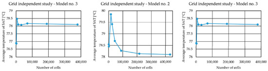
Figure 4.
Results of the grid independent study for models no. 1, no. 2, and no. 3.
Based on the results of the grid-independent study, we selected models with a computational network that ensured both a rational computing time and the accuracy of the results. The parameters of the computing network for individual models are summarized in Table 2.
Table 2.
The basic characteristic of used numerical meshes.
3. Results
The results of individual simulations, which compared the impact of three design concepts during two operation scenarios, were summarized in a spreadsheet and edited in a graphic editor for the needs of data presentation. The first part of the results is focused on the charging phase and monitors the necessary time to reach the average or minimum temperature of the volume representing the SAT, to 58 °C, which represents the temperature at which the given PCM changes its state. Figure 5 shows the course of the average temperature, from which it is possible to read the fastest achievement of the desired temperature of 58 °C for concept no. 1, which uses the gyroid structure for SAT as well as for the heat transfer medium. The results, of course, are not surprising, but the quantification of the charging rate with the use of the gyroid thermal conducting structure is a fundamental condition for designing the final prototype of the thermal energy storage unit. From the point of view of the evaluation of the time frame, the fastest charge took 1340 s (concept no. 1); 2180 s (concept no. 2), and 3510 s (concept no. 3). From this comparison, it is possible to draw the conclusion that even the use of the gyroid structure only in the SAT volume shortens the charging time by approximately one third.
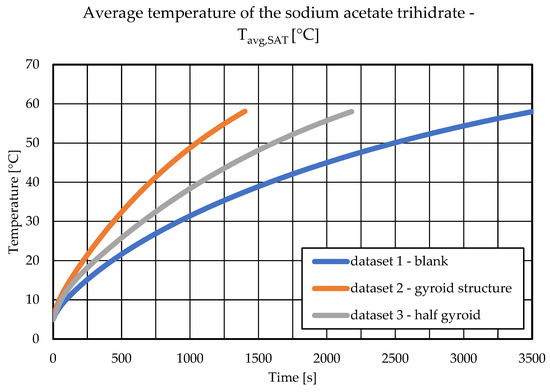
Figure 5.
The dependency of time and average temperature of the volume representing the SAT in area under 58 °C.
For a more accurate description of the situation, it is better to choose the minimum temperature of the SAT volume as the control parameter. In this case, it is also considered a value of 58 °C, but when following the minimum value, it is possible to claim that every place in the SAT volume has reached the required temperature. The time course of reaching the minimum temperature is shown in Figure 6. Here it can be seen not only different times of reaching a given temperature but also a different shape of the curve. In concept no. 1, the monitored temperature was reached in 2060 s, with concept no. 2 in 3060 s and with concept no. 3 in 6500 s. The shape of the curve for concept no. 2, but especially for concept no. 3, indicates a slower start of the entire process when in the first tens or hundreds of seconds, the temperature rises only slowly.
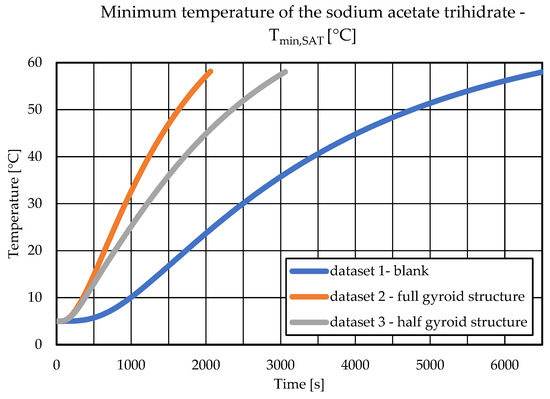
Figure 6.
The dependency of time and minimum temperature of the volume representing the SAT in area under 58 °C.
A significant advantage of concept no. 1 is the display of the temperature map of the gyroid structure in time steps from the start of the simulation until the minimum temperature of 58 °C is reached in the entire SAT volume, which is depicted in Figure 7. From each view, one can see a gradual increase in the temperature of the gyroid structure in the direction of the flow of the heat transfer medium (from left to right). Heat flow gradually increases the temperature of the gyroid structure, which is in contact with the SAT volume. The advantage of the used geometry of the gyroid structure consists in increasing the heat exchange surface in a uniform way throughout the entire volume of the proposed concept of the thermal energy storage unit.
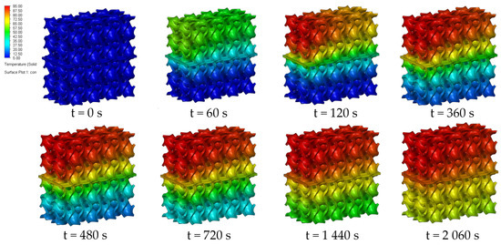
Figure 7.
The surface temperature of the gyroid structure in the charging process.
The overall results of the change in the temperature of the gyroid structure and SAT volume during the charging of model no. 1 is summarized in Figure 8, where it is possible to see the temperature map in a longitudinal section view. The display of the initial tens of seconds is particularly interesting, where one can see a significant increase in the temperature of the gyroid structure due to the heat flow from the heat transfer medium with a temperature of 95 °C. In the following course of charging, there is a gradual increase in the lower parts of the gyroid structure, which allows the transfer of heat flow into the SAT volume and its gradual temperature rise to monitored 58 °C.
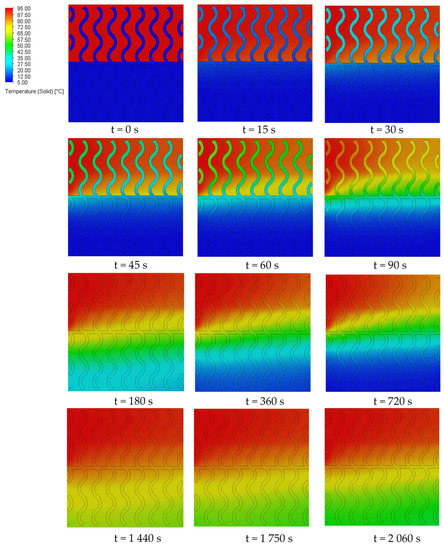
Figure 8.
Temperature map of SAT and gyroid structure in longitudinal section view of model no. 1.
Figure 9 displays heat maps in a section view of models no. 2 and no. 3 and provides a mutual comparison of the charging process with both present and absent gyroid thermally conductive structures. In the case of concept no. 3, the size of the heat exchange surface is clearly absent. The heat exchange process is limited only to the immediate vicinity of the surface (object), separating the channel from the flowing heat transfer medium and the SAT volume. The entire process is influenced by the formation of the boundary layer on both sides of the heat exchange surface. In this case, the SAT temperature changes evenly in parallel layers, but the required temperature is reached over a longer period of time than the other two concepts. In concept no. 2, more significant differences in the distribution of the regions of the temperature map can be seen, which is caused by the gradual increase in the temperature of the gyroid structure in the direction of the flowing heat transfer medium.
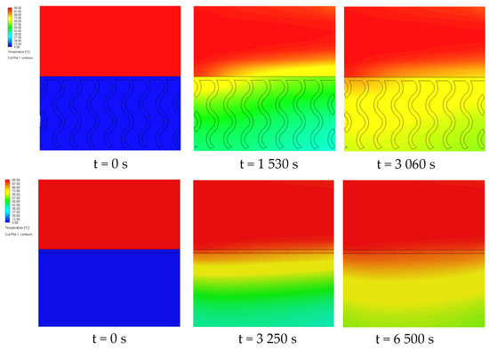
Figure 9.
Temperature map of SAT and gyroid structure in longitudinal section view of model no. 2 and model no. 3.
The results of the second part of the simulations, which covered the discharge process, are summarized in two graphs in Figure 10 (left and right). The resulting curves depict the output temperature of the heat transfer medium from the models of the three proposed concepts. The essential finding from this comparison is not only the achievement of the absolute highest temperature but also the time course, i.e., the rate of reaching this value. Even in this case, model no. 1 reaches, logically, the highest values thanks to the significantly higher value of the heat exchange surface between the SAT and the heat transfer medium. However, the difference in models no. 2 and no. 3, i.e., in the present, or the absence of a thermally conductive structure in the volume of the PCM, is fundamental. In the case of the incorporation of the gyroid structure, the temperature in the first seconds after initiation reached its maximum at 16.3 °C, while the concept without the gyroid structure reached its maximum earlier, but the temperature reached 9.6 °C. The maximum temperature is reached by concept no. 1, with a value of 23.4 °C. Figure 10 (left) depicts the absolute decrease in time 7200 s from the beginning of the initiation of the heat-accumulating substance. At the same time, in the simulation, concept no. 3 reaches only a third; specifically, half of the average temperature compared to concepts no. 1 and no. 2. Figure 10 (right) depicted an even more interesting view of the heat transfer medium temperature increase in the first 1000 s, where a rapid increase in temperature is visible in concept no. 2 compared to concept no. 3, but this increase stops quickly and the temperature of the heat transfer medium at the outlet no longer increases. A slight oscillation of the values of the monitored parameter in concept no. 1 is caused by the formation of backflow in the peripheral parts of the model due to the densification of the computational mesh.
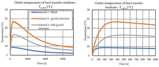
Figure 10.
Dependency of time and heat transfer medium outlet temperature in time 7200 s (left) and time 1000 (right).
A view of the temperature map in the section view of model no. 1 is shown in Figure 11, which shows the time course of the temperature change of the SAT and the gyroid structure. From the comparison, a rapid increase in the temperature of the SAT at the beginning of the simulation is clearly visible, which gradually increases the temperature of the gyroid structure in the channel with the heat transfer medium. As a result of which, the heat transfer medium gradually increases its temperature up to the point where the temperature of the SAT begins to decrease, and thermal energy is depleted.
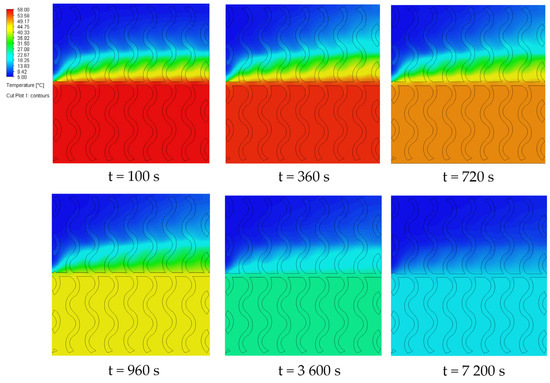
Figure 11.
Temperature map of SAT and gyroid structure in longitudinal section view of model no. 1 in the discharging phase.
The flow of the heat transfer medium in a channel with a gyroid structure, i.e., in concept no. 1, is shown in Figure 12. On the three perpendicular velocity flow maps that also depict streamlines, one can see an increase in flow velocity in narrowed areas; however, overall, thanks to the low velocity, locations in the structure with an increase in the value of turbulent kinetic energy, or locations where there is suppressed laminar flow in favor of turbulent flow are absent. According to low values of the flow velocity, one can conclude that the presented spatial structure would have an insignificant effect on the pressure loss of the flowing heat transfer medium.
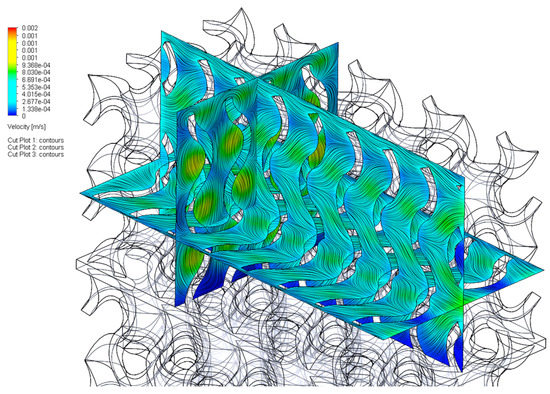
Figure 12.
Velocity map and streamlines of heat transfer medium.
4. Discussion
The introduction of the gyroid structure into the SAT volume represents a significant benefit from the point of view of thermal conductivity, as is demonstrated by the charging and discharging rate of the proposed concept of the thermal energy storage unit. However, when introducing technological improvements to SAT, it is necessary to think not only from the point of view of thermophysical properties but also from the point of view of the economic, manufacturing, or environmental demands. In a closer analysis of the concept that introduces a thermally conductive structure into the SAT volume, metals have an unrivaled advantage, especially in terms of structural strength, thermal conductivity, and specific heat capacity. However, even with the current state of technology and knowledge, the difficulty of producing such a structure from metals represents a significant obstacle, especially for scientific teams working from countries outside the mainstream of scientific research funding. However, when considering the required parameters of designs, or prototypes of thermal energy storage units in terms of heat flows, the use of metals can be exaggerated.
In specific cases, it might be appropriate to use a material with a lower thermal conductivity with the possibility of simplifying the production of a gyroid structure. Such an option is the use of additive manufacturing methods, using thermally conductive filaments based on a thermoplastic polymer. The use of this material is possible by standard 3D printers, thanks to which the creation of prototypes, or their modification, can be quick and affordable.
The gyroid structure, as a representative of the triply periodic minimal surface, offers unique properties from the point of view of directional homogeneity of the essential characteristics (strength of the structure, fluid characteristics, and heat conduction). This is advantageous when creating final prototypes by 3D printing processes, when the key problem is the orientation of the model with respect to the layering of the filament, while the homogeneity of the gyroid structure greatly facilitates the solution of the given problem. The often-declared problem of thermally conductive filaments, which reach higher values of the thermal conductivity coefficient in the plane of application of the filament layer than between the individual layers, also enters the issue of model orientation. However, the homogeneity of the gyroid structure significantly eliminates this issue. The use of the proposed concept of the gyroid structure, which is filled with SAT, brings not only a significant improvement of the key parameters of the charging rate (specifically, of the discharge of the thermal energy storage unit) but also in connection with the correctly selected thermally conductive filament, the simplicity of production.
The research in question confirmed the suitability of implementing a thermally conductive structure in the SAT volume compared to a thermal energy storage unit without a thermally conductive structure. The proposed design achieved shorter charging times, as well as a higher heat flow to the heated transfer medium in the discharge process. Further steps in the development process will be aimed at finding a design (or construction layout) that will ensure the maximization of the heat exchange process while maintaining problem-free reproducibility by standard 3D printing methods. Here, it is necessary to consider the orientation of the individual functional parts of the model with respect to the printing plane and the spatial limitation, which can lead to the segmentation of the total volume of the heat exchanger made of a gyroid structure.
5. Conclusions
The use of renewable energy sources, or sources of waste heat, requires a wider introduction of efficient thermal energy storage units; for example, with the use of PCM, which eliminates heat losses in the phase when the heat storage is in the so-called charged state. The disadvantage of PCM is their low thermal conductivity in the solid phase, i.e., in the key phase of the charging and discharging process. This problem can be solved by several approaches, one of which is the introduction of a thermally conductive matrix into the PCM volume. The presented contribution deals with the evaluation of the impact of the implementation of the gyroid thermally conductive structure in the SAT volume by comparing three concepts of structural arrangement depending on the degree of implementation of the gyroid structure in the design. The manufacturing of a gyroid structure from metals represents a relatively complex production problem. Therefore, the authors are considering the creation of this structure using additive manufacturing methods using a commercially available thermally conductive filament based on a thermoplastic polymer, which will save not only production costs but also will simplify production. The comparison of the design concepts was carried out based on monitoring the thermophysical parameters of the PCM and heat transfer medium in a time of 7200 s, in two work scenarios that simulated charging of the thermal energy storage unit to a temperature of 58 °C and discharging of the thermal energy storage unit at an ambient temperature of 5 °C. The significance of the results lies in the quantification of the introduction of a thermally conductive structure into the SAT volume, which shortened the time needed to charge the thermal energy storage unit, as well as ensuring a higher heat flow in the discharge process, which was manifested by an increase in the temperature of the heat transfer medium.
Author Contributions
Conceptualization, M.B., D.K. and R.R.; methodology, M.B.; data curation, D.K.; writing—original draft preparation, M.B.; writing—review and editing, R.R.; visualization, M.B.; supervision, D.K.; funding acquisition, M.B. All authors have read and agreed to the published version of the manuscript.
Funding
This research was funded by the Scientific Grant Agency of the Ministry of Education, Science, Research and Sport of the Slovak Republic, grant number VEGA 1/0290/21, Study of the behavior of heterogeneous structures based on PCM and metal foams as heat accumulators with application potential in technologies for obtaining and processing of the earth resources.
Data Availability Statement
Not applicable.
Conflicts of Interest
The authors declare no conflict of interest.
References
- Arteconi, A.; Hewitt, N.J.; Polonara, F. State of the art of thermal storage for demand-side management. Appl. Energy 2012, 93, 371–389. [Google Scholar] [CrossRef]
- Streimikiene, D.; Kyriakopoulos, G.L.; Lekavicius, V.; Pazeraite, A. How to support sustainable energy consumption in households? Acta Montan. Slovaca 2022, 27, 479–490. [Google Scholar]
- Rabe, M.; Drożdż, W.; Widera, K.; Łopatka, A.; Leżyński, P.; Streimikiene, D.; Bilan, Y. Assessment of energy storage for energy strategies development on a regional scale. Acta Montan. Slovaca 2022, 27, 163–177. [Google Scholar]
- Suresh, C.; Saini, R.P. Review on solar thermal energy storage technologies and their geometrical configurations. Int. J. Energy Res. 2020, 44, 4163–4195. [Google Scholar] [CrossRef]
- Chavan, S.; Rudrapati, R.; Manickam, S. A comprehensive review on current advances of thermal energy storage and its applications. Alex. Eng. J. 2022, 61, 5455–5463. [Google Scholar] [CrossRef]
- Mahon, H.; O’Connor, D.; Friedrich, D.; Hughes, B. A review of thermal energy storage technologies for seasonal loops. Energy 2022, 239, 122207. [Google Scholar] [CrossRef]
- Sarbu, I.; Sebarchievici, C. A Comprehensive Review of Thermal Energy Storage. Sustainability 2018, 10, 191. [Google Scholar] [CrossRef]
- Tyagi, V.V.; Chopra, K.; Sharma, R.K.; Pandey, A.K.; Tyagi, S.K.; Ahmad, M.S.; Sarı, A.; Kothari, R. A comprehensive review on phase change materials for heat storage applications: Development, characterization, thermal and chemical stability. Sol. Energy Mater. Sol. Cells 2022, 234, 111392. [Google Scholar] [CrossRef]
- Takahiro Nomura, T.; Noriyuki Okinaka, N.; Tomohiro Akiyama, T. Technology of Latent Heat Storage for High Temperature Application: A Review. ISIJ Int. 2010, 50, 1229–1239. [Google Scholar] [CrossRef]
- Sarbu, I.; Dorca, A. Review on heat transfer analysis in thermal energy storage using latent heat storage systems and phase change materials. Int. J. Energy Res. 2019, 43, 29–64. [Google Scholar] [CrossRef]
- Mellouli, S.; Alqahtani, T.; Algarni, S. Parametric Analysis of a Solar Water Heater Integrated with PCM for Load Shifting. Energies 2022, 15, 8741. [Google Scholar] [CrossRef]
- Beaupere, N.; Soupremanien, U.; Zalewski, L. Influence of Water Addition on the Latent Heat Degradation of SAT. Appl. Sci. 2021, 11, 484. [Google Scholar] [CrossRef]
- Zhou, G.; Li, Y.; Zhu, M. Experimental investigation on space heating performances of supercooled thermal storage units with SAT. Energy Build. 2022, 271, 112329. [Google Scholar] [CrossRef]
- Wang, G.; Liao, Z.; Xu, C.; Englmair, G.; Kong, W.; Fan, J.; Wei, G.; Furbo, S. Design optimization of a latent heat storage using SAT. J. Energy Storage 2022, 52, 104798. [Google Scholar] [CrossRef]
- Myat, L.P.; Ahmad, M.S.; Pulidindi, I.N.; Algarni, H.; Kumar, L.; Kalam, A.; Wageh, S.; Pandey, A.K.; Akbar, A.; Selvaraj, J. Effect of Polyethylene Glycol and Activated Carbon Macroparticles on Thermal Conductivity of Paraffin Wax for Thermal Storage Applications. Polymers 2022, 14, 4181. [Google Scholar] [CrossRef]
- Hua, W.; Zhang, X.; Muthoka, M.J.; Han, X. Preparation and Performance Analysis of Modified SAT. Materials 2018, 11, 1016. [Google Scholar] [CrossRef] [PubMed]
- Wang, S.; Wang, C.; Hussain, M.B.; Cheng, X.; Wang, Z. Study on Performance Improvement of SATin Thermal Energy Storage System by Disturbance. Processes 2022, 10, 1093. [Google Scholar] [CrossRef]
- Johansen, J.B.; Dannemand, M.; Kong, W.; Fan, J.; Dragsted, J.; Furbo, S. Thermal Conductivity Enhancement of SATby Adding Graphite Powder and the Effect on Stability of Supercooling. Energy Procedia 2015, 70, 249–256. [Google Scholar] [CrossRef]
- Dannemand, M.; Johansen, J.B.; Simon Furbo, S. Solidification behavior and thermal conductivity of bulk SATcomposites with thickening agents and graphite. Sol. Energy Mater. Sol. Cells 2016, 145, 287–295. [Google Scholar] [CrossRef]
- Lin, Y.; Jia, Y.; Guruprasad Alva, G.; Fang, G. Review on thermal conductivity enhancement, thermal properties and applications of phase change materials in thermal energy storage. Renew. Sustain. Energy Rev. 2018, 82, 2730–2742. [Google Scholar] [CrossRef]
- Garay Ramirez, B.M.L.; Glorieux, C.; San Martin Martinez, E.; Flores Cuautle, J.J.A. Tuning of thermal properties of SATby blending with polymer and silver nanoparticles. Appl. Therm. Eng. 2014, 62, 838–844. [Google Scholar] [CrossRef]
- Wang, Z.; Huang, G.; Jia, Z.; Gao, Q.; Li, Y.; Gu, Z. Eutectic Fatty Acids Phase Change Materials Improved with Expanded Graphite. Materials 2022, 15, 6856. [Google Scholar] [CrossRef] [PubMed]
- Liu, G.; Li, Y.; Wei, P.; Xiao, T.; Meng, X.; Yang, X. Thermo-Economic Assessments on a Heat Storage Tank Filled with Graded Metal Foam. Energies 2022, 15, 7213. [Google Scholar] [CrossRef]
- Hassan, F.; Hussain, A.; Jamil, F.; Arshad, A.; Ali, H.M. Passive Cooling Analysis of an Electronic Chipset Using Nanoparticles and Metal-Foam Composite PCM: An Experimental Study. Energies 2022, 15, 8746. [Google Scholar] [CrossRef]
- Falcone, M.; Rehman, D.; Dongellini, M.; Naldi, C.; Pulvirenti, B.; Morini, G.L. Experimental Investigation on Latent Thermal Energy Storages (LTESs) Based on Pure and Copper-Foam-Loaded PCMs. Energies 2022, 15, 4894. [Google Scholar] [CrossRef]
- Al-Najjar, H.M.T.; Mahdi, J.M.; Bokov, D.O.; Khedher, N.B.; Alshammari, N.K.; Catalan Opulencia, M.J.; Fagiry, M.A.; Yaïci, W.; Talebizadehsardari, P. Improving the Melting Duration of a PV/PCM System Integrated with Different Metal Foam Configurations for Thermal Energy Management. Nanomaterials 2022, 12, 423. [Google Scholar] [CrossRef]
- Chen, Q.; Wu, J.; Sun, K.; Zhang, Y. Numerical Study of Heat Transfer Enhancement by Arc-Shaped Fins in a Shell-Tube Thermal Energy Storage Unit. Energies 2022, 15, 7799. [Google Scholar] [CrossRef]
- Zhao, L.; Xing, Y.; Liu, X.; Luo, Y. Thermal performance of SAT based composite phase change material for thermal energy storage. Appl. Therm. Eng. 2018, 143, 172–181. [Google Scholar] [CrossRef]
- Szatkiewicz, T.; Laskowska, D.; Bałasz, B.; Mitura, K. The Influence of the Structure Parameters on the Mechanical Properties of Cylindrically Mapped Gyroid TPMS Fabricated by Selective Laser Melting with 316L Stainless Steel Powder. Materials 2022, 15, 4352. [Google Scholar] [CrossRef]
- Anwajler, B. The Thermal Properties of a Prototype Insulation with a Gyroid Structure—Optimization of the Structure of a Cellular Composite Made Using SLS Printing Technology. Materials 2022, 15, 1352. [Google Scholar] [CrossRef]
- Gawronska, E.; Dyja, R. A Numerical Study of Geometry’s Impact on the Thermal and Mechanical Properties of Periodic Surface Structures. Materials 2021, 14, 427. [Google Scholar] [CrossRef]
- Wallat, L.; Altschuh, P.; Reder, M.; Nestler, B.; Poehler, F. Computational Design and Characterisation of Gyroid Structures with Different Gradient Functions for Porosity Adjustment. Materials 2022, 15, 3730. [Google Scholar] [CrossRef] [PubMed]
- Ivanova, T.N.; Kuric, I.; Korshunov, A.I.; Koretckiy, V.P. Increasing the efficiency of operating time and reducing maintenance time of transport systems. Acta Montan. Slovaca 2022, 27, 723–736. [Google Scholar]
- Venkata Phani Babu, V.; Veeresh Kumar, G.B. A review on 3D printing process on metals and their surface roughness and dimensional accuracy. Mater. Today: Proc. 2022, 64, 525–530. [Google Scholar]
- Basavraj Gadagi, B.; Ramesh Lekurwale, R. A review on advances in 3D metal printing. Mater. Today Proc. 2021, 45, 277–283. [Google Scholar] [CrossRef]
- Devanuri, J.K.; Gaddala, U.M.; Kumar, V. Investigation on compatibility and thermal reliability of phase change materials for low-temperature thermal energy storage. Mater. Renew. Sustain. Energy 2020, 9, 1–16. [Google Scholar] [CrossRef]
- Cabeza, L.F.; Illa, J.; Roca, J.; Badia, F.; Mehling, H.; Hiebler, S.; Ziegler, F. Immersion corrosion tests on metal-salt hydrate pairs used for latent heat storage in the 32 to 36 °C temperature range. Mater. Corros. 2002, 52, 140–146. [Google Scholar] [CrossRef]
- Al-Ketan, O.; Abu Al-Rub, R.K. Multifunctional Mechanical Metamaterials Based on Triply Periodic Minimal Surface Lattices. Adv. Eng. Mater 2019, 21, 1900524. [Google Scholar] [CrossRef]
- Solidworks Flow Simulations Technical Reference, Dassault Systemes. 2017. Available online: https://www.solidworks.com/product/solidworks-flow-simulation (accessed on 10 October 2022).
- Sobachkin, A.; Dumnov, G. Numerical Basis of CAD-Embedded CFD. Solidworks Technical Reference, Dassault Systemes. 2017. Available online: https://www.solidworks.com/sw/docs/flow_basis_of_cad_embedded_cfd_whitepaper.pdf (accessed on 10 October 2022).


Disclaimer/Publisher’s Note: The statements, opinions and data contained in all publications are solely those of the individual author(s) and contributor(s) and not of MDPI and/or the editor(s). MDPI and/or the editor(s) disclaim responsibility for any injury to people or property resulting from any ideas, methods, instructions or products referred to in the content. |
© 2022 by the authors. Licensee MDPI, Basel, Switzerland. This article is an open access article distributed under the terms and conditions of the Creative Commons Attribution (CC BY) license (https://creativecommons.org/licenses/by/4.0/).