Article

Experimental Investigation of Heat Pipe Inclination Angle Effect on Temperature Nonuniformity in Electrical Machines

1
Advanced Electric Drive Centre, Yongjiang Laboratory, Ningbo 315202, China
2
Key Laboratory of More Electric Aircraft Technology of Zhejiang Province, University of Nottingham Ningbo China, Ningbo 315100, China
3
Power Electronics, Machines and Control Group, University of Nottingham, Nottingham NG7 2RD, UK
*
Author to whom correspondence should be addressed.
Energies 2023, 16(1), 350; https://doi.org/10.3390/en16010350
Submission received: 30 November 2022 / Revised: 23 December 2022 / Accepted: 26 December 2022 / Published: 28 December 2022

Abstract

:
Heat pipes (HPs) are gaining increasing popularity in the propulsion motors of transportation electrification due to their remarkable thermal properties. However, the inclination angle affects the HP thermal performance and, thus, results in temperature nonuniformity, which may generate unbalanced thermal stress on the motor. Such an issue has received less attention to date and requires corresponding solutions. This article performs an experimental investigation on motor temperature nonuniformity with HPs and further proposes an improved structure to address this problem. A specimen based on a stator-winding assembly with HPs is prepared and a dedicated experimental platform is established. Then, the temperature distribution across the specimen is studied, followed by an evaluation of the effects of current density and wind velocity. To compensate for the degradation of HP thermal performance, an improved structure with enlarged fins is proposed, and the equilibrium point is determined by fitting and comparing the obtained temperature data. Finally, the proposed structure is verified by the comparison between the original and improved specimens. The experimental results show that the non-uniform temperature distribution is significantly improved, with the temperature range and standard deviation reduced by 42% and 44.3%, respectively.

1. Introduction

With increasingly stringent environmental requirements and carbon emissions legislation, accelerated electrification at an unprecedented rate is underway in the context of transportation, such as aircraft, electric vehicles, rail and marine. High-power-density (kW/kg or kW/L) propulsion motors are at the heart of the related research topics and are being extensively investigated for enhanced output capacity [1,2,3]. The thermal management of electrical machines is one of the dominating factors in achieving a lightweight and compact structure; thus, advanced cooling systems are required for more effective heat dissipation [4,5,6].
With the merits of high equivalent thermal conductivity, small volume, light weight, low cost, easy molding and zero consumption of external energy, heat pipes (HPs) are being extensively applied in motor cooling scenarios, with remarkable cooling effectiveness reported [7,8,9,10,11]. During the application, HPs are normally installed in different orientations, which results in various inclination angles, i.e., the angle between the HP and the vertical direction, as shown in Figure 1a. According to the internal structure and working principle of the HP, it is clear that the gravitational effect of the interior working medium at different inclination angles could affect its backflow and, further, the HP thermal conductivity. Such effects can be divided into: (i) the gravity-assisted case (evaporator below condenser), where gravity assists the backflow of the working medium and the HP offers a favorable thermal performance; (ii) the gravity-opposed case (evaporator above condenser), where gravity blocks the reflux and, thus, degrades the HP thermal properties, as detailed in Figure 1b [12,13]. The above descriptions and analyses have also been confirmed by several studies in the field of thermology and mechanical engineering [14,15,16,17,18,19,20,21,22]. However, the HP inclination effect on motor cooling effectiveness and temperature nonuniformity, which needs to be fully investigated when applying HPs in motor cooling systems, has received less attention to date in the existing literature.
Figure 2 illustrates some of the typical HP applications in motor cooling systems [23,24]. It can be observed that HPs are installed evenly along the circumference into different modules of the motor to shorten the heat path from the heat source to the coolant. Under such circumstance, HPs operate at different inclination angles and provide different thermal benefits, which further results in a non-uniform temperature distribution in electrical machines. However, there are few published quantitative studies on this topic, and cooling structures for a more uniform temperature distribution are still lacking for engineers. Therefore, an intensive study is required to explore such effects, maximize the HP thermal benefits, and make motor temperature distribution more uniform.
This study aims to fill the above knowledge gaps. The main contributions of this article are summarized as follows.
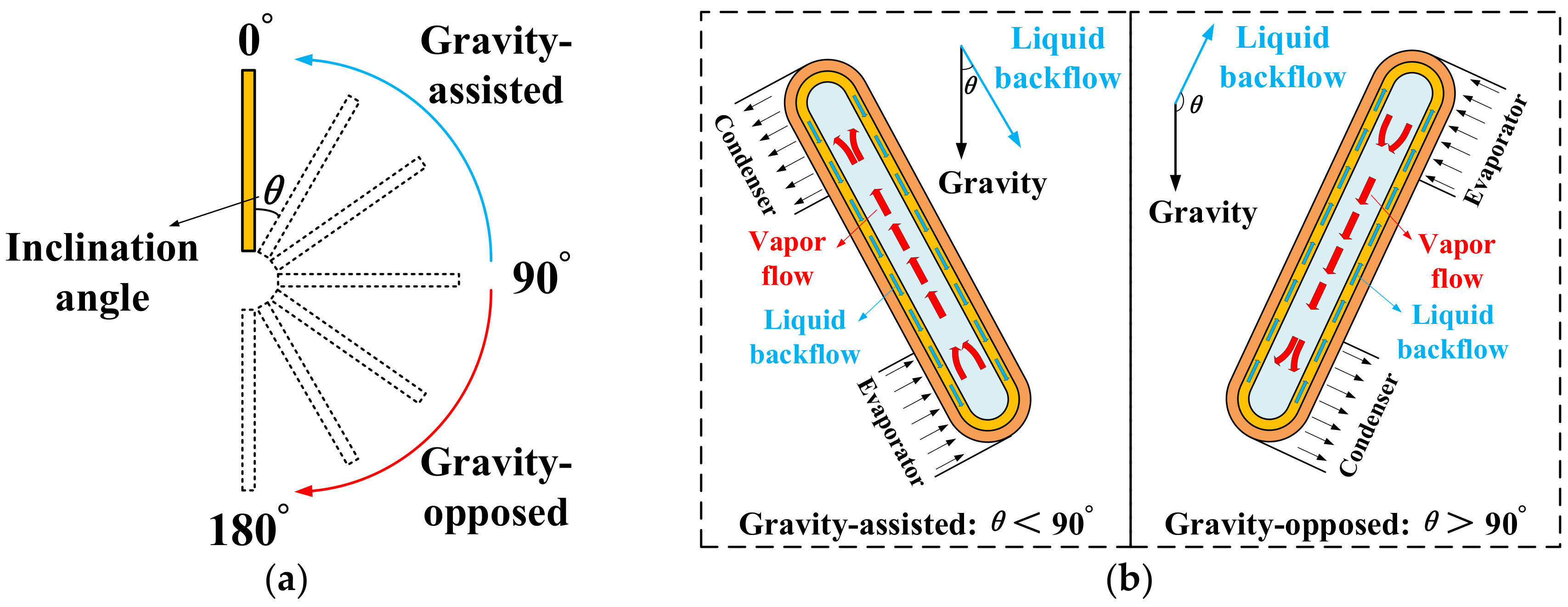
  • This paper quantitatively investigates motor temperature nonuniformity due to the HP inclination angle effect through experimentations.
  • An improved structure with enlarged fins is proposed to compensate for the degradation of HP thermal performance and improve motor temperature distribution.
  • The proposed structure is verified by comparative experiments between original and improved specimens.
The remainder of this article is structured as follows. Section 2 prepares an experimental specimen and establishes a dedicated experimental platform for thermal testing. An experimental study on temperature nonuniformity is performed in Section 3, followed by the effects of critical factors. Section 4 proposes an improved structure, and the rational solution is determined through comparative experiments. Section 5 experimentally verifies the proposed improved structure. Finally, a conclusion is drawn in Section 6.

2. Experimental Setup

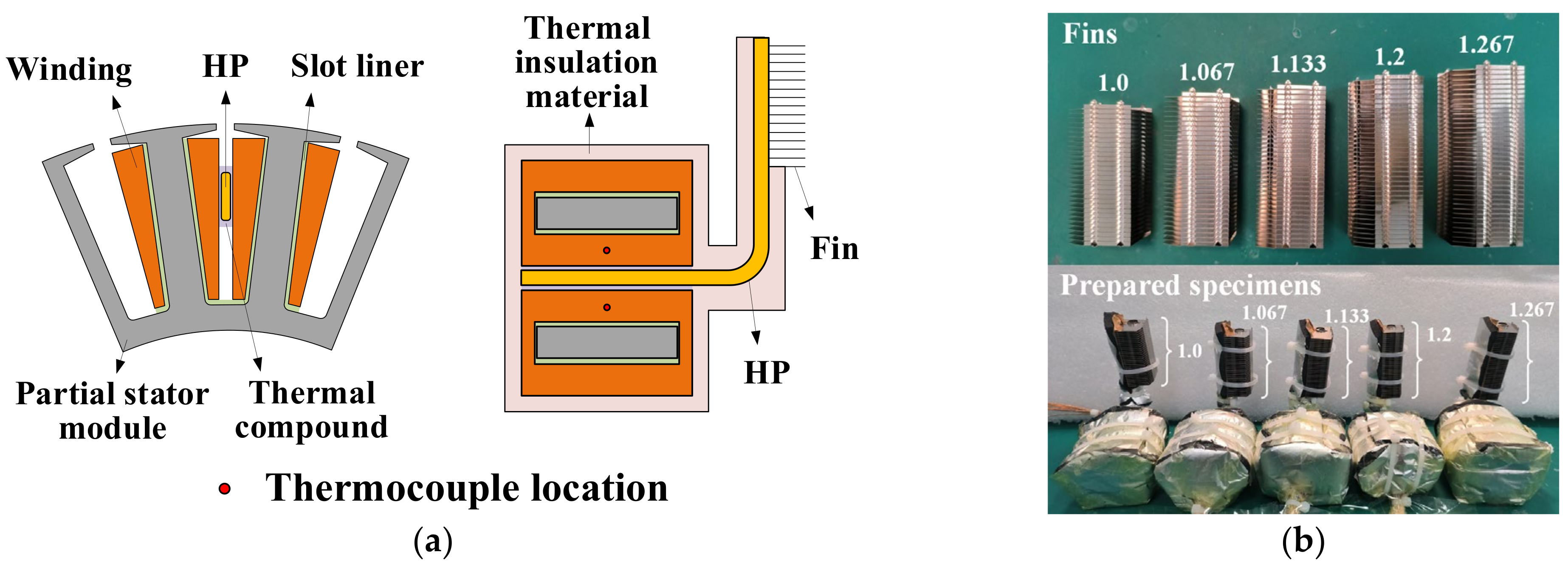
2.1. Specimen Preparation

To fully evaluate the HP inclination angle effect on temperature nonuniformity in electrical machines, an experimental specimen based on a 24-slot stator-winding assembly with a diameter of 160 mm is prepared for experimental investigation, according to the assembly diagram in Figure 3. A concentrated layout is adopted for copper wires wound on a stator module, which is made by mounting silicon steel sheets into a stator frame. The insulation boards and slot liner of class F insulation are applied between the winding and stator module for insulation consideration. HPs are evenly inserted into the clearances of different winding layers along the circumference, and the identical aluminum fins are attached to the HPs to enlarge the convective area. When the HPs are installed into the windings, tiny gaps at the contact interfaces between windings and HPs are inevitable, which largely reduces the contact area and weakens the heat transfer. To address this challenge, a type of 92% micronized diamond added a thermal compound (IC diamond) with high equivalent thermal conductivity of 2000 W/m·K to enhance heat conduction. During the application process, sufficient thermal compound is evenly applied to the contact interface to ensure favorable thermal conductivity between the windings and the HPs. Furthermore, due to the non-adhesive characteristics of IC diamond, the HPs are further bonded to the windings by using thermally conductive silica gel at the end region of the specimen to ensure a reliable connection. The entire specimen is wrapped with multi-layer thermal insulation material (Nitrile rubber), except for the fins, to ensure that the heat generated is only dissipated by the HPs, thus fully investigating the HP inclination angle effect on the motor temperature nonuniformity, as detailed in Figure 4. Finally, the prepared specimen is affixed to a dedicated iron bracket through a flange for thermal testing. As the preferred choice in the context of motor cooling, the copper-liquid HP with sintered wick structure is employed in this study, and its detailed parameters are listed in Table 1.

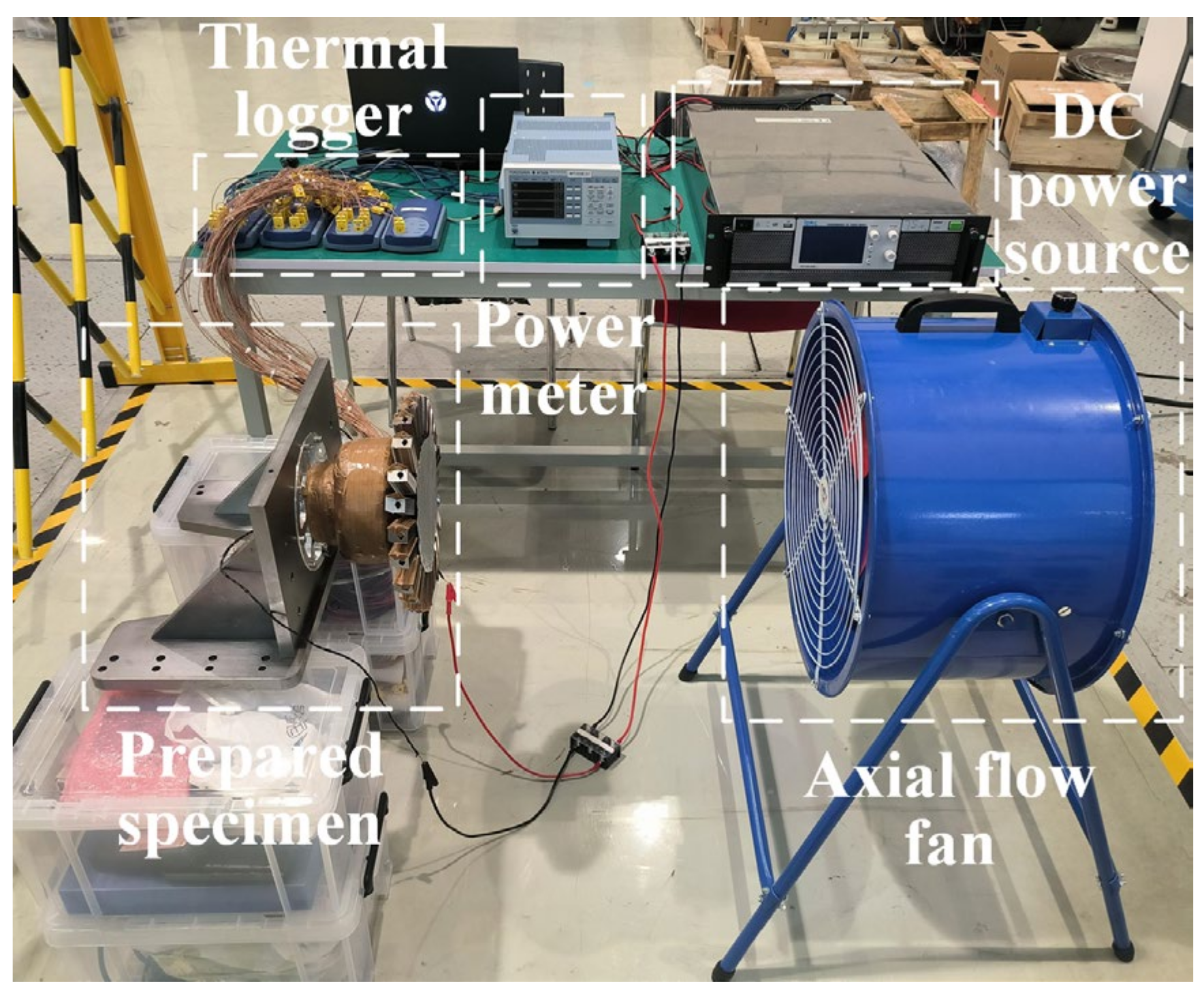
2.2. Experimental Platform

A dedicated experimental platform is established to perform thermal testing on the prepared specimen, as shown in Figure 5. The windings in the specimen are powered by an adjustable DC power supply (DSP1050-42WE), which operates in constant current mode throughout the experiment. A power meter (YOKOGAWA WT333E) is connected in series into the loop to measure the current fed into the specimen. A high-power axial flow fan equipped with a variable speed controller is employed to provide cooling air. The electric fan blades are large enough to ensure a uniform wind velocity across the specimen. Moreover, the center height of the fan is adjusted to be the same as the specimen, and the horizontal distance between them is also kept constant during the experiment. The temperature distribution across the specimen is recorded by thermal loggers (Pico TC-08).

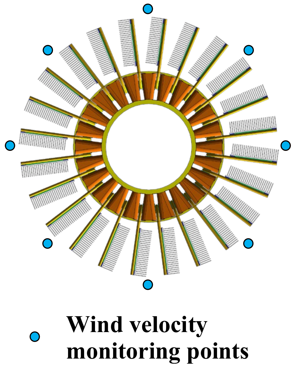
2.3. Instrumentation and Data Acquisition

The experimental platform is instrumented with a range of sensors and instruments to monitor the data required for further analysis, including temperature, current and wind velocity. To obtain a detailed temperature profile across the specimen, a total of 48 K-type thermocouples are affixed to the in-slot windings with cyanoacrylate adhesive, where half of them is located in the center of the left winding layers beside the HP and the other half on the right, as described in Figure 6. The average winding temperature is adopted to characterize the thermal performance of the inserted HP, which refers to the mean value of two thermocouples in each slot. The temperature sensor readings are logged every second throughout the experiment. When the temperature variation within 5 min is smaller than 0.2 K, thermal equilibrium is considered to be achieved, and the sensors’ data are recorded. Due to the choice of insulation class for the slot liner, the maximum winding temperature of the specimen is strictly limited to 130 °C for safety and reliability. Regarding uniform wind distribution, the wind velocities at the eight monitoring points around the specimen are collected by an anemometer (OMEGA HFF144), as detailed in Figure 7. The deviation between the obtained data is less than 5%, which indicates a uniform cooling condition for the specimen and identical wind velocity for each fin.

3. Experiments and Results

3.1. Data Processing

To better demonstrate the HP inclination angle effect on temperature distribution, the HPs mounted in the specimen are numbered clockwise from 1 to 24, where HPs 1 to 12 and 13 to 24 are orientated symmetrically to each other, as presented in Figure 8. Furthermore, the whole specimen is divided into four regions to facilitate the demonstration of comparative experimental results, as listed in Table 2.
All temperature data are collected when the experiment reaches steady state, i.e., when the temperature variation within 15 min is less than 0.5 K, the steady state is considered to be achieved. The temperature range △T and standard deviation σ are introduced in this study to characterize the temperature distribution across the specimen. The temperature range refers to the difference between the maximum and minimum winding temperatures across the specimen, given by
T = T max T min
Moreover, the standard deviation of the winding temperature is calculated by
σ = i = 1 n T i T a v 2 / n
where σ is the standard deviation, n is the number of HPs, Ti is the average winding temperature corresponding to the ith HP, Tav is the average temperature of all windings. The aforementioned parameters △T and σ are in K (Kelvin), and Ti and Tav are in °C (Celsius).

3.2. Temperature Distribution

To distinctly demonstrate temperature nonuniformity due to the HP inclination angle effect, thermal testing is conducted on the prepared specimen at a current density of 20.6 A/mm2 and a wind velocity of 2.2 m/s. The winding temperature distribution across the specimen is presented in Figure 9, where different colors represent the corresponding regions defined above. It can be noted that the temperature distribution presents an overall uptrend with the increasing HP inclination angle, with △T of 22.4 K and σ of 6.81 K. For the gravity-assisted cases in regions I and II, the HPs (1–6, 19–24) demonstrate favorable cooling effectiveness, with lower steady-state winding temperatures in the top half of the specimen. However, the winding temperatures at the bottom half of the specimen are significantly higher, as the HPs (7–18) in regions III and IV are at greater inclination angles, which degrades the HPs’ thermal performance.

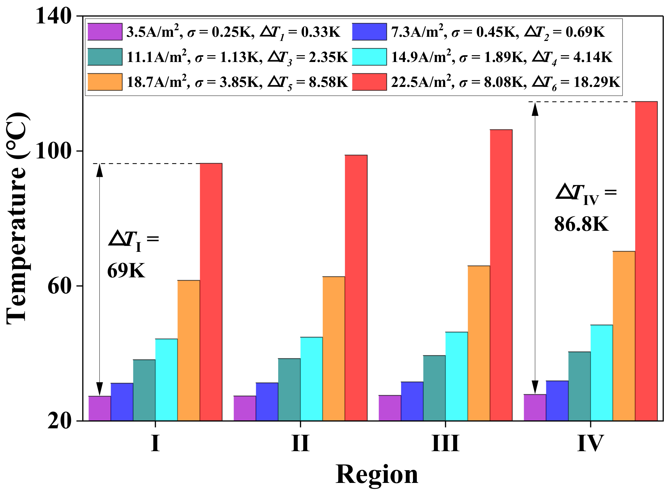
3.3. Effect of Current Density

Current density, a critical factor to characterize the thermal load, is one of the most concerning issues during the thermal design of an electrical machine. Its impact on the temperature distribution of the electrical machine with HPs is evaluated by comparative tests under different current densities, i.e., 3.5 A/mm2, 7.3 A/mm2, 11.1 A/mm2, 14.9 A/mm2, 18.7 A/mm2 and 22.5 A/mm2. To ensure that the winding temperature is within the permissible range at high current densities, the wind velocity is adjusted to a maximum of 4.7 m/s. As presented in Figure 10, all winding temperatures increase significantly with increasing current density, and the growth rate gets higher, especially after 14.9 A/mm2. A comparatively uniform temperature distribution is observed under lower current densities, while it deteriorates sharply at higher current densities, where △T rises from 0.33 K to 18.29 K and σ from 0.25 K to 8.08 K. The main reason lies in that the current density effect on temperature rise enhances with the increasing HP inclination angle, i.e., there is a temperature difference of 69 K in region I between 3.5 A/mm2 and 22.5 A/mm2, while it is 86.8 K in region IV. Thus, it can be inferred that the current density has a great impact on the motor temperature distribution, and particular attention should be paid to such temperature nonuniformity in high-power-density motors with HPs.

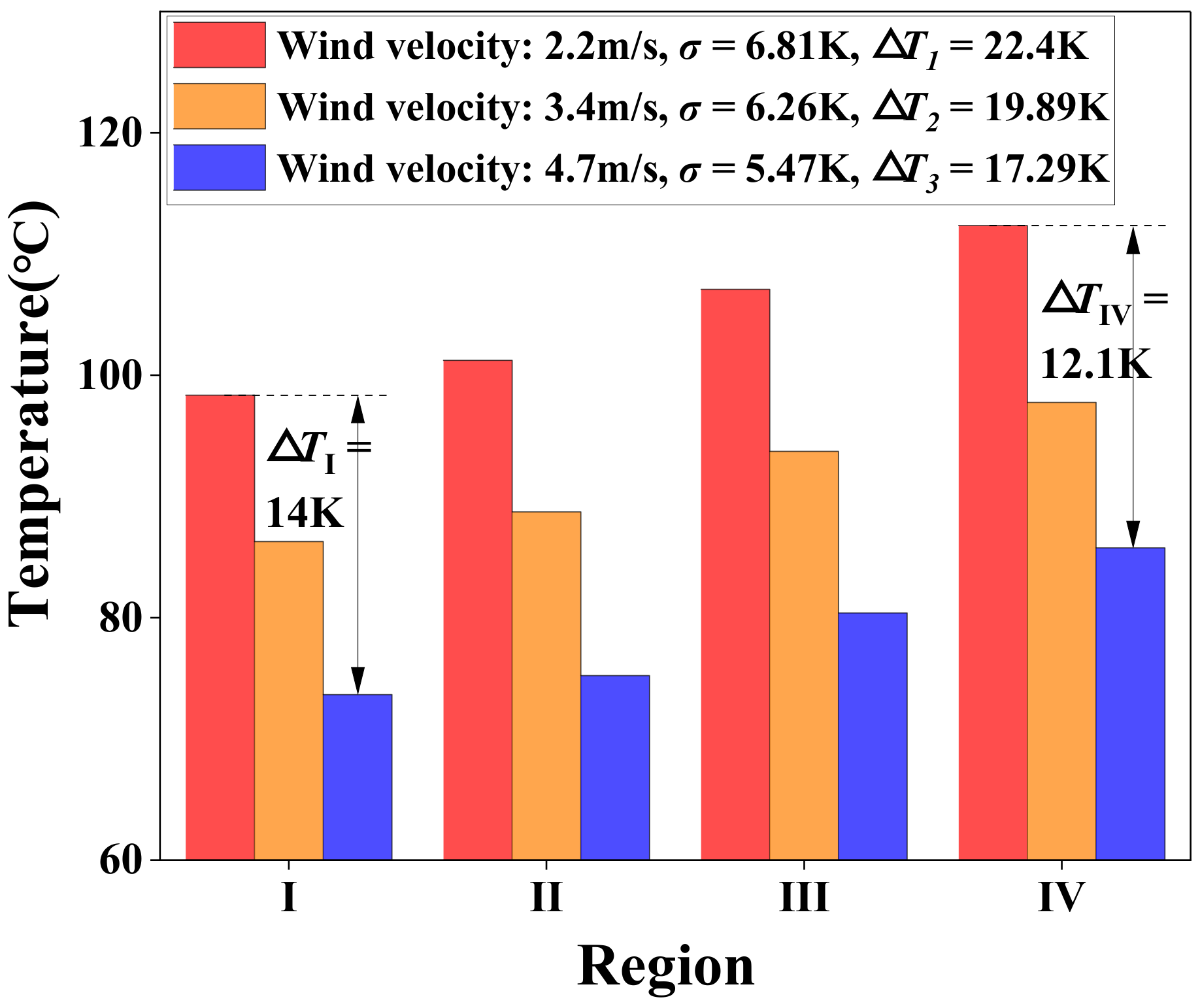
3.4. Effect of Wind Velocity

Wind velocity is a very important aspect of the cooling condition of electrical machines, especially for air-cooled motors. Its effect on temperature nonuniformity is experimentally investigated under different values, i.e., 2.2 m/s, 3.4 m/s and 4.7 m/s, and the same current density as Part B. As displayed in Figure 11, the winding temperatures decrease with enhanced wind velocity, and the temperature nonuniformity is slightly improved with △T reduced from 22.4 K to 17.29 K and σ from 6.81 K to 5.47 K. The main reason may lie in the poorer HP thermal performance when the operating temperature is too low. The working temperature for HPs in region I is lower than region IV due to the inclination angle effect, which results in worse thermal benefits, and it is less affected by incremental wind velocity. Consequently, as the wind velocity increases, the winding temperatures in region I decline slower than region IV, thus leading to a smaller temperature range and more uniform temperature distribution across the specimen.

4. An Improved Structure for More Uniform Temperature Distribution

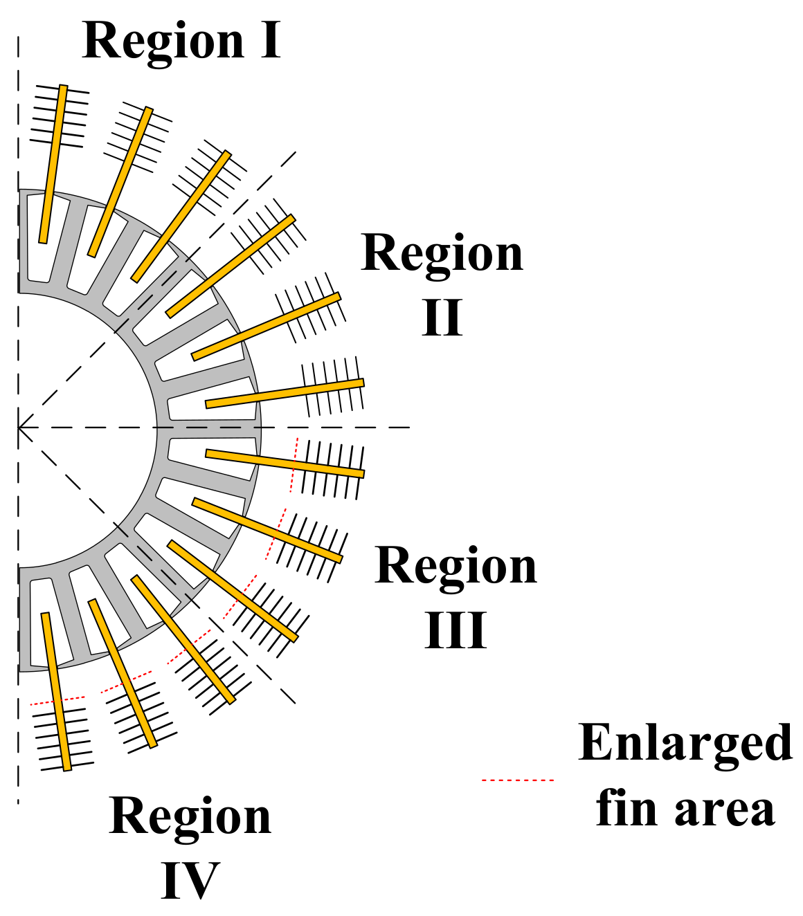
4.1. Proposed Improved Structure

To address such temperature nonuniformity, an improved structure with properly enlarged fins in the bottom half of the specimen is proposed to compensate for the degraded thermal performance of the HPs in the gravity-opposed case, as shown in Figure 12. It is evident that the thermal property of the HP and fin assembly is difficult to accurately quantify through analytical calculations due to the phase change principle of the HP and the convective heat transfer of the fin. Therefore, an experimental approach is adopted in this study to determine a reasonable fin size by comparing the cooling effectiveness of the fins with different surface areas.
In this study, the actual surface area of the original fin arrays with 15 pieces of fins is assumed as a base value, and the surface areas of linearly expanded fins are converted into per unit (pu) value, i.e., 1 (15), 1.067 (16), 1.133 (17), 1.2 (18) and 1.267 (19), as listed in Table 3.

4.2. Specimens Preparation with Different Fin Areas

To experimentally quantify the rational fin area, five specimens with the above candidate surface areas are prepared for the comparative tests. The schematic of the specimen construction based on partial stator lamination is illustrated in Figure 13a, which is processed in a similar way to the previous full stator-winding specimen. Copper wires are wound on a three-slot stator lamination, and slot liner is used for insulation consideration, as well. Identical HPs are inserted into the clearances of different winding layers, and fins in the different sizes listed above are attached to the HPs. To increase the contact area and enhance thermal conductivity, sufficient thermal compound (IC diamond) is applied to the contact interfaces between the HPs and the windings. The entire specimen is also wrapped with multi-layer thermal insulation material, except for the fin, to purely study the compensation effect of different fin areas. Two thermocouples are affixed to the center of the windings for temperature monitoring, and the average winding temperature is used to characterize the cooling performance of the fins. The prepared specimens corresponding to five different fin areas are presented in Figure 13b.

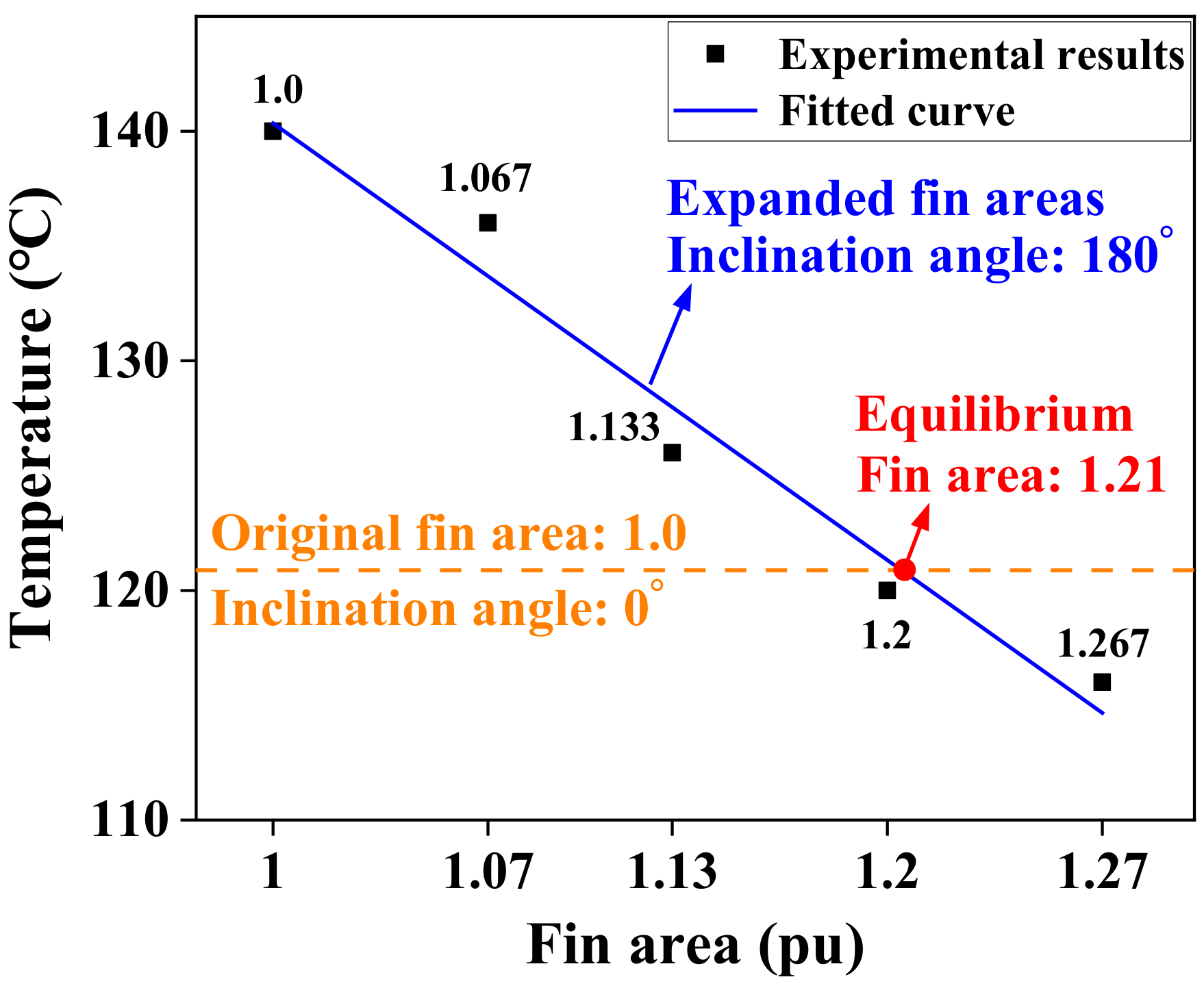
4.3. Experiments and Results

As presented in Figure 14, the specimen with the original fin area (1.0) is tested vertically upwards (0°) to simulate the gravity-assisted case, where the obtained steady-state winding temperature is defined as a reference value. Afterwards, the specimens with expanded fins are tested vertically downwards (180°) to simulate the gravity-opposed case, and the measured winding temperatures are compared to the reference value to evaluate the compensation effectiveness. The above two sets of experiments are conducted under the same conditions as the thermal test in Section 3.2, i.e., a current density of 20.6 A/mm2 and wind velocity of 2.2 m/s.
Figure 15 presents the results of the comparative experiments. The steady-state winding temperature for the original fin area (1.0) at an inclination angle of 0° is plotted as an orange dashed line. In addition, the temperature data for the linearly expanded fins at 180° are fitted as a solid blue line. Thus, the intersection of the above two lines is the equilibrium point, which indicates that the enhanced convective area can fully compensate the degradation in HP thermal performance due to the inclination angle effect. The fin area corresponding to the equilibrium point is 1.21; thus, 1.20 is determined as a reasonable fin size, which is the closest and feasible solution for enlarged fin arrays.

5. Experimental Verification

A new specimen based on the improved structure proposed above is prepared for experimental verification, according to the same assembly method in Figure 3. To reduce unnecessary workload and save time, copper wires are wound on half of the stator stack, with HPs mounted from the topmost to the bottommost end of the module, which fully covers the inclination angle from 0° to 180°, as illustrated in Figure 16.

5.1. Temperature Distribution for the Improved Specimen

The newly prepared specimen is tested under the same conditions as the original one in Section 3.2, and the experimental results are presented in Figure 17. Compared to the original specimen, a more uniform temperature distribution is clearly observed, with △T declining from 22.4 K to 13 K and σ from 6.81 K to 3.79 K. The winding temperature in the gravity-opposed zone is significantly reduced, though no great change is discovered in the gravity-assisted region, which is in line with the expected results of the improved structure. Additionally, it can also be noted that the winding temperature is the highest in Region II, while it is lowest in Region III. The main reason lies in that the HPs equipped with original fins in Region II are at a larger inclination angle (compared to Region I), while the HPs in Region III with enlarged fins have a smaller inclination angle (compared to Region IV).

5.2. Effects of Current Density and Wind Velocity

The effects of current density and wind velocity on the improved specimen are also studied under the same conditions as the original specimen, as presented in Figure 18 and Figure 19. As the current density increases and the wind velocity declines, a similar degradation trend in temperature nonuniformity is observed from the histograms, where a gradual growth in the temperature range and standard deviation is discovered.
Regarding typical current density intervals under different cooling methods in electrical machines, it is generally recognized that the achievable range is from 0–5 A/mm2 under natural convection, 5–12 A/mm2 under forced convection and 12–30 A/mm2 under liquid cooling [25]. Figure 18b shows a comparison of the temperature distribution between the original and improved specimens corresponding to the aforementioned current density intervals. It is evident that there is no significant change under light thermal load due to a comparatively uniform temperature distribution in the original specimen, with △T and σ less than 1 K. However, there is a considerable improvement in temperature distribution for the improved specimen under heavy thermal load, where △T and σ are reduced by 63.3% and 48.8%, respectively, at a current density of 22.5 A/mm2. As for the wind velocity effect in Figure 19b, a similar pattern can be obtained, in which △T and σ decline at an accelerated rate with the enhanced wind velocity, i.e., 41.9% and 44.3%, respectively, at the wind velocity of 2.2 m/s, while 65.9% and 52.5%, respectively, at 4.7 m/s.
It can be concluded from the above results and analyses that the proposed improved structure could provide a more uniform temperature distribution across the specimen, particularly under heavy thermal load and high wind velocity conditions, which is crucial for high-power-density motors.

6. Conclusions

In this study, the non-uniform temperature distribution due to the HP inclination angle effect has been investigated through experimentations on a prepared stator-winding specimen. Results have shown a clear temperature nonuniformity across the specimen, with a temperature range of 22.4 K and standard deviation of 6.81 K, which further deteriorates with the increasing current density and declining wind velocity. To address this issue, this study has proposed an improved structure with enlarged fins for the HPs in the gravity-opposed zone. The reasonable fin size has been determined to be 1.2 times the original area by fitting and comparing the winding temperatures of candidate fins with different surface areas. After the preparation of the improved specimen with enlarged fins, it has been experimentally verified that a more uniform temperature distribution was obtained under the same conditions, with a 42% reduction in temperature range and 44.3% in standard deviation. Moreover, a more distinct improvement in temperature distribution could be observed under heavy thermal load and enhanced wind velocity, which indicates a more effective enhancement in thermal management for high-power-density motors.
The conducted research and proposed improved structure could serve as practical guidelines for the implementation of a more uniform temperature distribution in electrical machines with HPs.

Author Contributions

Conceptualization and investigation, X.Z.; methodology and writing—original draft preparation, H.Z. (Han Zhao); writing—review and editing, J.L. and F.Z.; validation, Y.Z., H.Y. and Z.N.; supervision, D.G. and H.Z. (He Zhang). All authors have read and agreed to the published version of the manuscript.

Funding

This research was funded by Ningbo Key Technology Research and Development Programme, grant number 2021Z035. This research was also funded by Ministry of Science & Technology under National Key R&D Program of China, grant number 2021YFE0108600. This research was also funded by the Key International Cooperation of National Natural Science Foundation of China, grant number 51920105011.

Data Availability Statement

The data presented in this study are available on request from the corresponding author.

Conflicts of Interest

The authors declare no conflict of interest.

References

  1. Zhang, F.; Gerada, D.; Xu, Z.; Zhang, X.; Tighe, C.; Zhang, H.; Gerada, C. Back-iron extension thermal benefits for electrical machines with concentrated windings. IEEE Trans. Ind. Electron. 2019, 67, 1728–1738. [Google Scholar] [CrossRef]
  2. Ramesh, P.; Lenin, N.C. High Power Density Electrical Machines for Electric Vehicles—Comprehensive Review Based on Material Technology. IEEE Trans. Magn. 2019, 55, 1–21. [Google Scholar] [CrossRef]
  3. Dong, C.; Qian, Y.; Zhang, Y.; Zhuge, W. A Review of Thermal Designs for Improving Power Density in Electrical Machines. IEEE Trans. Transp. Electrif. 2020, 6, 1386–1400. [Google Scholar] [CrossRef]
  4. Zhang, F.; Gerada, D.; Xu, Z.; Liu, C.; Zhang, H.; Zou, T.; Chong, Y.; Gerada, C. A Thermal Modelling Approach and Experimental Validation for an Oil Spray-Cooled Hairpin Winding Machine. IEEE Trans. Transp. Electrif. 2021, 7, 2914–2926. [Google Scholar] [CrossRef]
  5. Wu, S.; Tian, C.; Zhang, P.; Huang, X.; Shan, X. Design and Optimization Analysis of Composite Water Cooling System Based On High Power Density Motor. In Proceedings of the 2019 22nd International Conference on Electrical Machines and Systems (ICEMS), Harbin, China, 11–14 August 2019; pp. 1–6. [Google Scholar] [CrossRef]
  6. Li, L.; Zhang, J.; Zhang, C.; Yu, J. Research on Electromagnetic and Thermal Issue of High-Efficiency and High-Power-Density Outer-Rotor Motor. IEEE Trans. Appl. Supercond. 2016, 26, 1–5. [Google Scholar] [CrossRef]
  7. Yu, Z.; Li, Y.; Jing, Y.; Wang, J. Cooling System of Outer Rotor SPMSM for a Two-Seater All-Electric Aircraft Based on Heat Pipe Technology. IEEE Trans. Transp. Electrif. 2021, 8, 1656–1664. [Google Scholar] [CrossRef]
  8. Le, W.; Lin, M.; Lin, K.; Liu, K.; Jia, L.; Yang, A.; Wang, S. A Novel Stator Cooling Structure for Yokeless and Segmented Armature Axial Flux Machine with Heat Pipe. Energies 2021, 14, 5717. [Google Scholar] [CrossRef]
  9. Geng, W.; Zhu, T.; Li, Q.; Zhang, Z. Windings Indirect Liquid Cooling Method for a Compact Outer-Rotor PM Starter/Generator with Concentrated Windings. IEEE Trans. Energy Convers. 2021, 36, 3282–3293. [Google Scholar] [CrossRef]
  10. Sun, Y.; Zhang, S.; Chen, G.; Tang, Y.; Liang, F. Experimental and numerical investigation on a novel heat pipe based cooling strategy for permanent magnet synchronous motors. Appl. Therm. Eng. 2020, 170, 114970. [Google Scholar] [CrossRef]
  11. Fang, G.; Yuan, W.; Yan, Z.; Sun, Y.; Tang, Y. Thermal management integrated with three-dimensional heat pipes for air-cooled permanent magnet synchronous motor. Appl. Therm. Eng. 2019, 152, 594–604. [Google Scholar] [CrossRef]
  12. Reay, D.; McGlen, R.; Kew, P. Heat Pipes: Theory, Design and Applications; Butterworth-Heinemann: Oxford, UK, 2013. [Google Scholar]
  13. Faghri, A. Heat Pipes: Review, Opportunities and Challenges. Front. Heat Pipes 2014, 5, 2–4. [Google Scholar] [CrossRef] [Green Version]
  14. Alammar, A.A.; Al-Dadah, R.K.; Mahmoud, S.M. Numerical investigation of effect of fill ratio and inclination angle on a thermosiphon heat pipe thermal performance. Appl. Therm. Eng. 2016, 108, 1055–1065. [Google Scholar] [CrossRef]
  15. Hu, M.; Zheng, R.; Pei, G.; Wang, Y.; Li, J.; Ji, J. Experimental study of the effect of inclination angle on the thermal performance of heat pipe photovoltaic/thermal (PV/T) systems with wickless heat pipe and wire-meshed heat pipe. Appl. Therm. Eng. 2016, 106, 651–660. [Google Scholar] [CrossRef] [Green Version]
  16. Noie, S.; Emami, M.S.; Khoshnoodi, M. Effect of inclination angle and filling ratio on thermal performance of a two-phase closed thermosyphon under normal operating conditions. Heat Transf. Eng. 2007, 28, 365–371. [Google Scholar] [CrossRef]
  17. Tang, H.; Weng, C.; Tang, Y.; Lu, Y.; Fu, T. Effect of inclination angle on the thermal performance of an ultrathin heat pipe with multi-scale wick structure. Int. Commun. Heat Mass Transf. 2020, 118, 104908. [Google Scholar] [CrossRef]
  18. Yousefi, T.; Mousavi, S.; Farahbakhsh, B.; Saghir, M. Experimental investigation on the performance of CPU coolers: Effect of heat pipe inclination angle and the use of nanofluids. Microelectron. Reliab. 2013, 53, 1954–1961. [Google Scholar] [CrossRef]
  19. Zhang, S.; Chen, J.; Sun, Y.; Li, J.; Zeng, J.; Yuan, W.; Tang, Y. Experimental study on the thermal performance of a novel ultra-thin aluminum flat heat pipe. Renew. Energy 2019, 135, 1133–1143. [Google Scholar] [CrossRef]
  20. Hossein, K.; Toghraie, D. A comprehensive study of the performance of a heat pipe by using of various nanofluids. Adv. Powder Technol. 2017, 28, 3074–3084. [Google Scholar]
  21. Jin, K.; Tai, Y.; Toghraie, D.; Hekmatifar, M. The effects of nanoparticle percentages and an external variable magnetic field on the atomic and thermal behaviors in an oscillating heat pipe via molecular dynamics simulation. J. Mol. Liq. 2022, 360, 119570. [Google Scholar] [CrossRef]
  22. Mostafazadeh, A.; Toghraie, D.; Mashayekhi, R.; Akbari, O.A. Effect of radiation on laminar natural convection of nanofluid in a vertical channel with single- and two- phase approaches. J. Therm. Anal. Calorim. 2019, 138, 779–794. [Google Scholar] [CrossRef]
  23. Zhang, X.; Zhang, C.; Fu, P.; Zhang, C.; Li, L. A Novel Cooling Technique for the Windings of High-Torque-Density Permanent Magnet Machines. In Proceedings of the 2018 21st International Conference on Electrical Machines and Systems (ICEMS), Jeju, Republic of Korea, 7–10 October 2018; pp. 332–337. [Google Scholar] [CrossRef]
  24. Putra, N.; Ariantara, B. Electric motor thermal management system using L-shaped flat heat pipes. Appl. Therm. Eng. 2017, 126, 1156–1163. [Google Scholar] [CrossRef]
  25. Gai, Y.; Kimiabeigi, M.; Chong, Y.; Widmer, J.D.; Deng, X.; Popescu, M.; Goss, J.; Staton, D.A.; Steven, A. Cooling of Automotive Traction Motors: Schemes, Examples, and Computation Methods. IEEE Trans. Ind. Electron. 2019, 66, 1681–1692. [Google Scholar] [CrossRef]
Figure 1. HP inclination angle effect. (a) Schematic of HP inclination angle. (b) Schematic of gravitational effect on the backflow of the interior working medium under the gravity-assisted case and gravity-opposed case.
Energies 16 00350 g001
Figure 2. HP applications in electrical machines at different inclination angles. (a) A cooling system with HPs inserted into the windings [23]. (b) A cooling structure with HPs mounted in the casing [24].
Energies 16 00350 g002
Figure 3. Schematic of specimen construction based on a stator-winding assembly. (a) Specimen outline. (b) Detailed view.
Energies 16 00350 g003
Figure 4. Prepared specimen wrapped with multi-layer thermal insulation material.
Energies 16 00350 g004
Figure 5. Experimental platform.
Energies 16 00350 g005
Figure 6. Thermocouples affixation for each slot of the specimen.
Energies 16 00350 g006
Figure 7. Wind velocity monitoring points around the specimen.
Energies 16 00350 g007
Figure 8. Numbering and partitioning of HPs in the specimen.
Energies 16 00350 g008
Figure 9. Winding temperature distribution under a current density of 20.6 A/mm2 and wind velocity of 2.2 m/s.
Energies 16 00350 g009
Figure 10. Winding temperature distribution under a wind velocity of 4.7 m/s and different current densities (3.5 A/mm2, 7.3 A/mm2, 11.1 A/mm2, 14.9 A/mm2, 18.7 A/mm2 and 22.5 A/mm2).
Energies 16 00350 g010
Figure 11. Winding temperature distribution under a current density of 20.6 A/mm2 and different wind velocities (2.2 m/s, 3.4 m/s and 4.7 m/s).
Energies 16 00350 g011
Figure 12. Proposed improved structure to address temperature nonuniformity.
Energies 16 00350 g012
Figure 13. Specimen preparation with five different fin areas. (a) Schematic of the specimen construction based on a partial stator-winding assembly. (b) Five prepared specimens.
Energies 16 00350 g013
Figure 14. Specimen testing at an inclination angle of 0 and 180 degrees.
Energies 16 00350 g014
Figure 15. Winding temperature comparison of original fin at an inclination angle of 0° and expanded fins at 180°.
Energies 16 00350 g015
Figure 16. Prepared specimen with expanded fins in the bottom half.
Energies 16 00350 g016
Figure 17. Winding temperature distribution for the new specimen under a current density of 20.6 A/mm2 and wind velocity of 2.2 m/s.
Energies 16 00350 g017
Figure 18. Current density effect on temperature distribution. (a) Winding temperature distribution for the improved specimen under a wind velocity of 4.7 m/s and different current densities (3.5 A/mm2, 7.3 A/mm2, 11.1 A/mm2, 14.9 A/mm2, 18.7 A/mm2 and 22.5 A/mm2). (b) Comparison of △T and σ between the original and improved specimens under typical current density intervals corresponding to common cooling methods.
Energies 16 00350 g018
Figure 19. Wind velocity effect on temperature distribution. (a) Winding temperature distribution for the improved specimen under a current density of 20.6 A/mm2 and different wind velocities (2.2 m/s, 3.4 m/s and 4.7 m/s). (b) Comparison of △T and σ between the original and improved specimens under different wind velocities.
Energies 16 00350 g019
Table 1. Parameters of the HPs used in this study.
ParametersValue
Length170 mm
Width8 mm
Thickness3 mm
MaterialCopper
Working mediumWater
Interior structureSintered wick structure
Table 2. Partitioning of HPs in the specimen.
DivisionHP NumberInclination Angle Range
Region I1, 2, 3, 22, 23, 240–45°
Region II4, 5, 6, 19, 20, 2145–90°
Region III7, 8, 9, 16, 17, 1890–135°
Region IV10, 11, 12, 13, 14, 15135–180°
Table 3. List of different fin areas.
SpecimenNo. of Fin ArraysFin Area (pu)Inclination Angle during Test
Original151.00° and 180°
Option 1161.067180°
Option 2171.133180°
Option 3181.2180°
Option 4191.267180°
Disclaimer/Publisher’s Note: The statements, opinions and data contained in all publications are solely those of the individual author(s) and contributor(s) and not of MDPI and/or the editor(s). MDPI and/or the editor(s) disclaim responsibility for any injury to people or property resulting from any ideas, methods, instructions or products referred to in the content.

