1. Introduction
Solar energy can be used for many applications, such as electric energy production via photovoltaic panels [
1] and solar-driven organic Rankine cycle plants [
2], or it can be converted to heat via solar collectors [
3,
4,
5]. Solar heat is mainly utilized for space heating and domestic hot water (DHW) applications, with solar DHW applications being one of the most viable renewable energy technologies. Of particular interest is that in the EU of 27, the industry of solar water heating systems (SWHSs) has been undergoing an annual reduction in new installations since 2010, with Cyprus and Greece being exceptions [
6]. Cyprus, Greece and Austria own the first three positions in the EU with the highest installed capacity of SWHSs per capita [
6].
A standard SWHS consist of solar collectors, where the conversion of solar energy to heat takes place, and a hot water storage tank. Conventionally, two main topologies can be used for the operation of the solar collectors in a SWHS: the natural circulation of the heat transfer fluid and the forced circulation via a pump [
7,
8,
9]. In the scientific literature, natural circulation systems are often called passive SWHSs, but a more widely used term is thermosyphon SWHSs. This type of system circulates the heat transfer fluid through the collector via the density difference between the bottom and the upper part of the collector. The density variation along the collector is formed due to the solar energy which heats up the absorber and this causes the density of the heat transfer fluid in the collector to decrease. Then, colder fluid from the tank of a higher density interchanges the warmer mass and, in turn, circulation through the collector is obtained. However, for the forced circulation systems, a circulation pump is responsible for removing the heat from the absorber. Commonly, the circulation pump is controlled by a differential thermostat which receives the temperatures from the bottom of the hot water tank and the outlet of the collector(s). A temperature difference of about 6 K to 8 K should be established for the operation of the circulation pump.
An experiment was carried out on a thermosyphon SWHS, with the aim to evaluate the distribution of the temperature and the flowrate on a flat plate collector (FPC) [
10]. The results shown a good agreement with the available mathematical models. The temperature difference between the inlet and the outlet of the FPC tended to be of a magnitude of 10 K, for a variety of ambient conditions [
7,
11]. Similarly, for a thermosyphon SWHS with a FPC, the pressure difference between the inlet and the outlet of the collector was estimated to be about 19 Pa with a flowrate of 0.005 L/s and to about 260 Pa with a flowrate of 0.05 L/s [
12]. The above pressure drops were estimated via a validated mathematical model of a thermosyphon SWHS.
Hasan [
13] undertook simulation-based work to evaluate the size and configuration of the DHW tank on a thermosyphon SWHS. Among the main findings of the study was that the direction (vertical or horizontal) in which the DHW tank is installed does not influence the energy performance of the SWHS. Additionally, the author concludes that the energy performance of the SWHS is assessed better via the solar fraction (SF) of the system, rather than the thermal performance of the solar collector or the useful heat produced. A forced circulation, with a heat pipe FPC SWHS was modeled via MATLAB and simulations were carried out for Fez, Morocco [
14]. The objective was to energetically and exergetically assess the SWHS. The results showed that the energy efficiency of the system was estimated to be up to 33% and the exergy efficiency up to 4%. At the same time, the SF was found to be 0.58. An annual performance comparative simulation-based study was carried out between similar SWHSs for Fuzhou city, China [
15]. The alteration between the systems was the layout of the tank, one was built as an indirect SWHS (heat exchanger between the fluid from the collector and the fluid in the tank) and the other as a direct SWHS (the fluid from the collector mixes with the fluid from the tank) [
7]. The main result was that for the direct SWHS, 15.07% of its heat stored int the tank was losses on an annual basis during nighttime, where at the same time, the indirect system had only 6.15% losses.
In existing research, a few experimental comparative studies between different types of SWHS can be found. Ananth and Jaisankar [
16] set up an experiment in Tamilnadu province in India, with the aim to evaluate the performance of a thermosyphon FPC-SWHS by applying a variety of layouts on the collector’s riser tubes (vertical pipes). Additionally, the assessment included the helical twisted tape in the riser tubes, then the use of a rod with the twisted tape and a variety of spacers (not covering part of the rod by the twisted tape). It was found that the helical twisted tape at the full length of the riser tube augmented the thermal efficiency of the collector by 0.15 compared to the case of the plain tubes. However, along with the improvement at the thermal efficiency of the collector by the utilization of the twisted tape, a pressure drop of 14 Pa was measured across the riser tubes. An experimental comparative study between a SWHS with 4 m
2 of a FPC and one with 3 m
2 with an evacuated tube collector was conducted in Dublin, Ireland [
17]. The systems were installed side by side, both systems were forced circulation, and both had a hot water tank of 300 L capacity. Additionally, equal DHW load was drawn off from both systems via solenoid valves and a programmable controller. The main aim of the work was to evaluate and compare the annual energy performance of the systems for northern maritime climate. The notable results were that regardless of the apparatuses’ area difference of the collectors, both SWHSs produce about equal heat, with 1984 kWh and 2056 kWh for the FPC and evacuated collector-based system, respectively; and the solar fraction (SF) of the systems turned out to be 0.38 and 0.40 for the FPC-SWHS and evacuated collector SWHS, respectively.
Currently, there insufficient comparative experiments between different types of SWHSs. A few of these works [
15,
16,
17] carried out trials with different types of collectors or alterations related to the layout of the system or the collector. To the best of the authors’ knowledge, no experimental study can be found that evaluates a forced circulation SWHS over an identical thermosyphon SWHS. With the aim of assessing the potential performance improvement which may be caused by the circulation pump to a SWHS, two alike SWHSs were installed at the Soft Energy Applications and Environmental Protection (SEA & ENVIPRO) laboratory of the University of West Attica, Athens, Greece. The two alike systems where installed side by side with the only difference being that one was a thermosyphon SWHS and the other was a forced circulation SWHS. DHW heating load was applied to both systems via solenoid valves and a microcontroller, which mimic the hourly DHW load profile. The trial period was from April to May 2022. The energy performance assessment of the SWHSs was based on two indicators: the SF and the overall thermal efficiency of the system.
2. Methodology
Two identical commercially available SWHSs were installed side by side (
Figure 1) on the roof of SEA & ENVIPRO, University of West Attica (38°0′7.11″ N/23°40′31.01″ E). The tilt angle of the FPC was 37.5° and their orientation was 30° west (γ = +30°). The two systems were similar, with the only difference being that one was a thermosyphon and the other was a forced circulation (FC) system, with a circulation pump of 10 W
max (
Figure 2).
The SWHSs were comprised of a selective painted FPC with an apparatus area of 1.5 m
2 and a DHW tank of 113 L capacity. Both tanks were horizontally installed with the internal diameter of the cylinder being 0.4 m. The SWHSs were indirect with a jacket (mantel) heat exchanger to enclose the water of the DHW (
Figure 2). Additionally, both systems were not equipped a temperature valve between the inlet and the outlet of the DHW tank. The heat removal fluid of the collectors (solar loop) was water. The utilization of water instead a glycol–water solution is a valid choice, since during this time of year, freezing temperatures are unlikely to occur in Athens. The main parameters of the systems are listed in
Table 1.
The circulation pump of the active SWHS was controlled via a differential thermostat which was built in the computer used as data logger (
Section 2.3). Additionally, the flowrate of the circulation pump was regulated by a pulse width modulator DC-to-DC power converter. The temperature at the outlet of the collector and at the bottom of the DHW tank was measured. The pump was switched on if ΔΤ between the collector (outlet) and the tank (bottom) was greater or equal to 6 K and the irradiance was higher than 200 W/m
2. The solar irradiance entered the pump’s control procedure with the aim of constraining unnecessary on and offs. Additionally, the circulation pump was switched off for a ΔΤ lower than 3 K, regardless of the irradiance level. A flowchart of the utilized methodology is depicted in
Figure 3 and the following sections provide a detailed description.
The analysis of the experimental results was made for two cases: the first was for three distinctive days with regard to the weather conditions and the second was for a four-day continuous operation of the SWHSs. Evaluation of the SWHSs under different weather conditions was carried out from 8:00 to 20:00 (except for the overcast day, where the ending time was 16:00 due to rain). The DHW demand was set to 90 L/per day (
Section 2.1) for this first case. During nighttime, the water from the DHW tanks was completely drawn off and replaced with cold water from the main. By doing so, both tanks contained water at an equal temperature level for the next day’s experiment. Regarding the evaluation of the SWHSs under nonstop operation for four days, this was conducted by the system operating for the entire day, with a break between 00:00 a.m. and 5:00 a.m., where nothing of interest occurred (
Figure 4). In this scenario, the tanks were not drawn off completely during nighttime, while the DHW load was regulated to 360 L per day (
Section 2.1).
2.1. DHW Load
With regard to the consumption of the DHW, the typical normalized profile suggested by Mutch [
18] was adopted and two daily DHW demands were applied (
Figure 4). The first DHW demand was 90 L per day and the second was four times bigger, at 360 L per day. The draw offs from the DHW tank were executed at the 25th minute of the hour and the required demand temperature was fixed at 50 °C. For the implementation of the DHW load, a microcontroller was programmed to automatically regulate the solenoid at the tank’s outlet (
Figure 2). A table with the hourly DHW demand was uploaded to the microcontroller and the water flowrate at the inlet of the tank was measured. By knowing the hourly DHW demand and the water withdrawal rates, the solenoid was activated or deactivated by the microcontroller with the aim of regulating the load.
2.2. Indicators for Energy Performance Analysis
Two energy performance indicators are used for the evaluation of the SWHS: the first is the SF and the second is the overall thermal efficiency (η
th). The SF illustrates the fraction of DHW load fulfilled by the SWHS (Equation (1)). The thermal efficiency of the SWHS is the ratio between the total energy delivered to the load and the total energy offered to the system. In this study, the major assumption made is that between the tank of the SWHS and the DWH load, no heat losses are considered. Thus, the temperature just after the outlet of the DHW tank is assumed to be equal to that delivered at the load. In reality, heat losses along the piping between the tank and the end user occur.
where
is the mass flowrate of the DHW, c
p is the specific heat capacity of the heat removal medium (water: 4185 J/kg K), T
o_tank and T
i_tank are the outlet and inlet water temperatures of the DHW, respectively, and T
d_DHW is the DHW demand temperature (50 °C). It is important to note that T
o_tank is assumed to be equal to the demanded temperature for instances when it is higher than 50 °C. The systems are not equipped with temperature valves and T
o_tank can occasionally be higher than 50 °C.
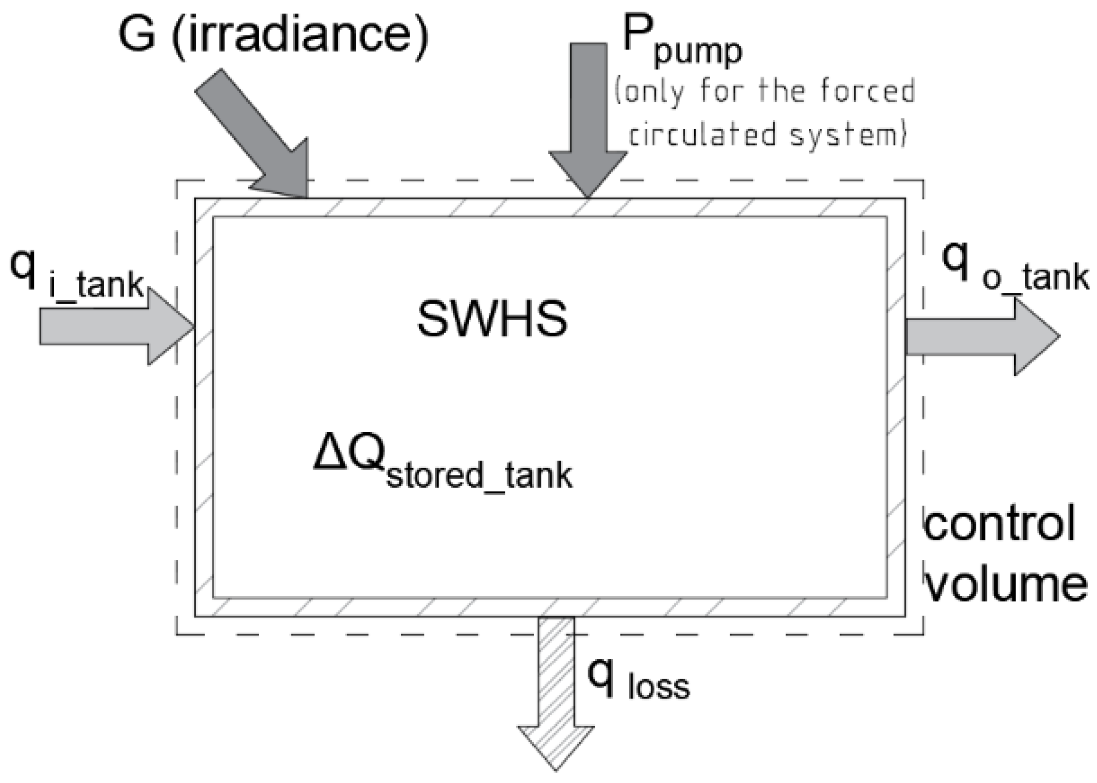
Figure 5 illustrates the energy flow of the SWHS across its control volume. In accordance with
Figure 5, Equation (2) illustrates the (first law) energy balance of the systems. It is worth mentioning that in
Figure 5, the heat stored in the collector is disregarded, due to the fact that it is significantly lower compared to the other heat flow components. Additionally, it did not examine the origins of the electricity consumed by the pump of the SWHS, which can be from a small PV panel or from the domestic power main. Further on, the electricity multiplied by the pump’s efficiency (η
pump) will be converted to pressure drop across the system and then to heat. In the thermal evaluation of the system, the electricity does not cross the control volume boundary of the system and only the pressure drop is considered (η
pump P
pump, Equations (2) and (3)). In other words, Equation (3) only gives the heat components, and the product of the pressure difference with the volume from the circulation pump is entered (work). For the sake of deriving the daily thermal efficiency from
Figure 5, the above assumptions are valid choices.
In accordance with
Figure 5, three energy rates contribute to the FC SWHS: the solar irradiance (G), the electric power of the pump (P
pump) and the stream of water entering the DHW tank from the main (q
i_tank,
Figure 5). For the thermosyphon SWHS, the power from the circulation pump is omitted. The energy rate leaving the control volume of the system can be as heat loss (q
loss) or as the stream of the DHW (q
o_tank). The change in the heat stored (Q
stored_tank) in the DHW tank is what remains to balance Equation (2). The absorbed solar heat by the collectors can be estimated by multiplying the irradiance with the product of the collector’s transmittance–absorptance (τα). Regarding the electricity consumed by the active system into the pump, this is converted mainly to flow work (
), and the energy needs to overcome the pressure losses (Δp) due to mass flow. Eventually the flow work is converted to heat.
where Q
stored_tank is the heat stored in the DHW tank, τα is the transmittance–absorptance product of the collector, G is the total incident solar irradiance, η
pump is the energy efficiency of the pump, P
pump is the electric power of the pump, q
loss is the heat rate loss, and q
DHW is the heat rate of the DHW.
The second index used for the analysis of the systems is η
th (daily or over a period). Based on Equation (2), Equation (3) is derived to estimate the thermal efficiency of the SWHS. This ratio (Equation (3)) depicts the heat supplied as DHW to the energy provided to the SWHS. The estimation of the thermal efficiency was based on measurements registered on minute basis. Thus, in Equation (3), the mass flowrate (
) is in L per minute and the other components are the minute-based measured mean values.
2.3. Data Logging and Error Analysis
The data logging was implemented via a Raspberry pi 4 (2 GB) single board computer. The script was written in Python programming language, with the aim of recording the values from the sensors and registering these on a spreadsheet. All the sensors were scanned continuously and their mean values were registered every minute.
Each SWHS was equipped with seven temperature sensors, as illustrated in
Figure 2 (T.1–T.7). Additionally, for both systems, the flowrate of the cold water entering from the main was measured, while for the forced circulation system, the flowrate of the collector was also measured (
Figure 2). For the present work, the volumetric flowrate was assumed to be equal to the mass flowrate, since water is used across the systems, and for the recorded temperatures, its density is about 1000 kg per m
3. Regarding the ambient parameters, the total incident solar irradiance was measured at the tilted level (37.5°), along with the wind speed (1 m above the collectors,
Figure 1) and the ambient relative humidity and the dry bulb ambient temperature of the air. In addition, the power consumption of the circulation pump was measured. In
Table 2, the utilized sensors and their uncertainty are listed.
Based on Equation (1) which estimates the SF, Equation (4) is utilized to calculate its uncertainty (u
SF). It is worth mentioning that the demand temperature (T
d_DHW) is a constant value (50 °C) and is not measured; therefore, no component of T
d_DHW exists in Equation (4). The average uncertainty of the SF (u
SF) is estimated via Equation (4) to be ±0.104 for both systems.
The uncertainty related to the thermal efficiency (Equation (3)) is estimated via Equation (5). The average uncertainty of η
th (u
ηth) is estimated via Equation (5)) to be ±0.16 for both systems.
3. Results and Discussion
The results are discussed in two sections: the first part (
Section 3.1) compares the DWHSs over three days with characteristic weather conditions and the second part (
Section 3.2) compares the SWHSs over a four-day period of continuous operation. The aim of the first (
Section 3.1) is to evaluate the potential influence of the ambient conditions on the energy performance of the systems and their comparison over a “cold start” (low level of heat to be stored in the tank and substantial DHW demand). It is to be noted that the experiment was carried out during the transition period, from spring to summer. Therefore, the results are, of course, for a variety of ambient conditions, but rather for mild temperatures (about 20 °C to 25 °C), which are far from the winter temperatures for Athens (about −2 °C to 10 °C). The goal of the second part is to illustrate in what way the diurnal heat storage component influences the energy performance of the investigated SWHSs.
3.1. Three Days of Independent Operation
The weather conditions during the three days are illustrated in
Figure 6 for the solar irradiance, in
Figure 7 for wind speed at one meter above the collectors, in
Figure 8 for the ambient dry bulb temperature and in
Figure 6. Total incident irradiance during the three days.
Figure 9 for the ambient relative humidity (RH), correspondingly. As it can be seen from these figures, the three days can be characterized distinctively as clear sky day, overcast day, and transient weather day.
The clear sky day has a dome-shaped solar irradiance, with a constantly increasing wind speed from about 1 m/s at 8:00 a.m. to about 5.2 m/s at 20:00. Regarding the ambient temperature, this follows the pattern of the irradiance, with a minimum value of 17 °C at the beginning and about 19 °C at the end of the day, with a peak of 23 °C at noon. The ambient RH oscillates between 42% and 35% throughout the day.
Regarding the overcast and the transient weather day, these have both periods with cloudiness and periods with a clear sky. The distinction between an overcast day and a transient weather day is difficult to be made here. In this study, the assumption of having days with quite similar weather conditions but with different names is made, with the aim of further studying both systems under unstable weather conditions. The main difference between these two days is that for the overcast day at 16:00, heavy cloudiness appeared with rain, and the transient weather day was without rain. Thus, it is unnecessary to further evaluate the overcast day, since the analysis stops at 16:00 due to rain. The ambient temperature for the overcast day was 17 °C at 8:00 a.m. and increased to 24.5 °C by the end of the measurement. The ambient temperature during the transient weather day starts at about 20 °C and ends (20:00) at 22 °C. The wind speed is light throughout the day for the overcast day. For the transient weather day, the wind speed is calm during the first few hours and then becomes moderate, at about 3–4 m/s.
3.1.1. DHW Temperatures in the Tanks
Clear Sky Day
In
Figure 10, the temperature of the water in the DHW tank is illustrated for all three levels (
Figure 2), for both SWHSs and for the clear sky day. Namely, the three levels are the water temperature at the bottom, in the middle and at the top of the tank. Along with the temperature of the water in the tanks, in
Figure 10 the DHW draw offs are shown. It is to be noted that both SWHSs share equal water draw offs as these are controlled by the microcontroller (
Section 2.1).
As shown in
Figure 10, the water temperature in both tanks (FC and thermosyphon SWHS) illustrates an increasing trend from the beginning to the end of the experiment. It is worth noting that for both SWHSs, the temperature at the top and at the middle are not influenced significantly by the draw offs. This is in contrast to the water temperature at the bottom, which is affected directly by the colder water entering the cylindrical tank from the main. A better understanding of this can be achieved by observing the main’s water inlet tube in
Figure 2, which is placed at the bottom of the tank and interacts directly with the water at that section.
Additionally, the FC SWHS illustrates a less stratified water temperature in the tank than the thermosyphon SWHS. Namely, the temperature difference of the water in the DHW tank between the top and the middle section at 14:00 is 7 K and 14 K for the FC and thermosyphon SWHS, respectively. Similarly, the difference between the middle and the bottom section is 2 K and 4 K for the FC and the thermosyphon SWHS, respectively. Until 16:00, the discrepancy of the water temperature in the tank illustrates an overall low value between the middle and the bottom layer compared to that between the top and the middle layer. After 16:00, the withdrawal of water substantially reduces the temperature of the water at the bottom and the difference from the middle section enlarges. The root cause of a better mixed water temperature in the tank for the FC SWHS is the flowrate of 104 L/h (fixed), imposed by the circulation pump (
Figure 2). The flowrate of the solar loop is higher for the FC than that of the passive SWHS; thus, a better heat transfer rate is established across the total area of the mantel heat exchanger. In contrast, the flowrate of the solar loop for the passive system is expected to be significantly lower than that of the FC and that causes a lower heat diffusion.
For the FC SWHS, the temperature at the upper part of the tank starts at 25 °C and reaches a maximum value of 58 °C at about 16:00. After this peak, the temperature drops smoothly to 55 °C until the end. The DWH draw offs are amounts of water removed from the tank’s upper section (
Figure 2); the delivered water completely fulfills the demand (50 °C) from about 14:15. With regard to the thermosyphon SWHS, the temperature at the top layer follows the trend of the FC system, by obtaining a slightly lower maximum value at about 16:00 and by being ready to totally fulfill the DHW demand from about 14:15.
The higher water temperatures at any level and for both systems are shown with lag in relation to the higher level of solar irradiance (
Figure 6). In particular, the higher solar irradiance was measured at about 14:30, when the higher temperature at the top layer was measured at about 16:00 (for both systems). This causes a time lag of about 1.5 h between the higher irradiance and the higher temperature at the top section. It is to be noted that the temperature of the water in the tank at any level is affected by the draw offs and an even higher temperature at an earlier time of day may have appeared due to the absence of the DHW demand. Lastly, the temperature at the middle section of the tanks illustrates its highest value with a greater lag with respect to the highest irradiance compared to that of the top section. This was caused by the large draw offs, which were demanded after 16:00 and forced the water in the tank to mix.
Overcast Day
In
Figure 11, the DHW tank temperatures for both systems and at all three temperature levels are illustrated along with the draw offs for the overcast day. The water temperatures in the DHW tank for both systems exhibit similar trends to those illustrated for the clear sky day. The temperatures increase steadily up to a maximum level of 52 °C at 15:45 for both systems. In the initial few hours of the experiment, a difference is recorded regarding the water temperature of the systems. Moreover, the FC system shows a greater stratification of water temperature than the thermosyphon system, with the difference between the top and the bottom level being 10 K and 3 K for the active and the passive SWHS, respectively. The reason for the greater stratification of the FC compared to that of the thermosyphon is due to the circulation pump, which was switched on after 9:00. The partly cloudy sky constrained the early initiation of the pump that morning (
Figure 6). This can be understood by observing
Figure 12 where the temperature difference of the outlet and the inlet in the FC system differs from that of the thermosyphon system, for the time period before and after 09:00. This is due to the control procedure of the pump, which turns on when ΔΤ is greater than 6 K and the irradiance is higher than 200 W/m
2 (
Section 2). After the initiation of the pump, the temperature across the tank of the FC system converges to a smaller stratification. Contrary to the FC system, the thermosyphon system operates without any restriction from the very first minute of the experiment (at 8:30, the irradiance was about 100 W/m
2;
Figure 6).
Transient Weather Day
The temperatures of the water in the DHW tanks for the transient weather day (
Figure 13) illustrate similar trends to those identified for the clear sky and overcast day. The highest temperature in the tank for both systems that day was measured to be slightly lower than 60 °C at 16:00 and at about 16:45 for the FC and the passive SWHS, respectively. The DHW demand (water temperature 50 °C) is fulfilled by the top water section of the tank. The DHW demand temperature was obtained by about 30 min earlier for the thermosyphon than the FC system. The faster response of the thermosyphon with regard to the water temperature at the top of the tank against the active SWHS was attained due to the interrupted operation of the circulation pump. As can be seen in
Figure 14, the operation of the pump is interrupted due to occasionally low irradiance, which switches off the pump (
Figure 6). It should be mentioned that the recording incident solar irradiance was recorded as mean minute-based value (as depicted in
Figure 6), while the control applied to the pump was recorded in real time with the measured values. During the experiment, there were instances where the irradiance was lower than 200 W/m
2; these cases were not recorded by the data logging procedure (seconds), but the operation of the circulation pump was affected. Regarding the middle and bottom sections of the tanks, the FC system was slightly quicker than the thermosyphon.
After the point with the highest temperature levels at the top sections of both tanks, a period with a temperature drop can be identified, from about 16:30 to 20:00 (
Figure 13). This declination was made by the large draw offs. As it can be observed, the decrease in the overall temperature in the tanks for this period was larger for the thermosyphon than for the FC system. The water temperatures in the tank of the FC system are higher at any level than those of the thermosyphon, at any specific time. Higher water temperatures in the tank entails more heat is stored. Thus, the high temperatures in the tank of the FC system are reduced less than those of the thermosyphon system, which justifies the smoother drop of the water temperatures for the FC system compared to the thermosyphon.
Summary
The list below summarizes the results related to the temperature of water in the DHW tank.
The temperature of the water in the tank of the FC system illustrated a lower stratification than that of the thermosyphon. Additionally, the temperature at the middle and at the bottom was found to be higher for the FC than the thermosyphon system in all cases.
For the clear sky day, the higher temperature difference between the top and the bottom section of the tank was found to be 9 K for the FC and 18 K for the thermosyphon system.
For the clear sky day, the temperature at the upper section of the tank was similar for both systems.
Both SWHSs were found to be capable of totally fulfilling the DHW load after 16:30.
Both systems were found to be capable of elevating the water temperature in the tank to 60 °C and that under the applied DHW load.
The passive system was found to be slightly more responsive than the FC system during the transient weather day, since it reached the threshold of 50 °C 30 min earlier.
3.1.2. Inlet and Outlet Temperature of the Collectors
The inlet and outlet temperature of the FPCs from both systems during the three experimental periods are shown in
Figure 12 for the clear sky day, in
Figure 15 for the overcast day and in
Figure 16 for the transient weather day, respectively. From all figures, it can be concluded that the temperature difference between the inlet and the outlet of the collectors (ΔT
coll) is larger for the thermosyphon SWHS than the FC system, due to the higher flowrate of the fluid in the FC system, caused by the pump. In particular, the average ΔT
coll for the passive system is at a magnitude of 14 K to 18 K, similar to the FC of about 4 K to 6 K. Existing experiments [
7,
11] have shown that for a variety of weather conditions, ΔT
coll has a magnitude of 10 °C. This value is somehow lower than the results of the current study, but a comparison cannot be made because these are different systems and are evaluated at different climates.
For the thermosyphon SWHS, the largest ΔT
coll by far is achieved during the clear sky day. It can be observed that for the passive SWHS, ΔT
coll increases proportionally to the solar irradiance. Furthermore, even during the partially cloudy days (
Figure 15 and
Figure 16), ΔT
coll for the thermosyphon exhibits high values, with the outlet temperature fluctuating with an overall increasing pattern. The abrupt drop in the outlet temperature during the absence of irradiance for both systems is constrained by the heat inertia of the absorber and of the water contained on it.
The collector’s inlet temperature (Ti_coll) of the FC system is higher than that of the thermosyphon at each time. Ti_coll is influenced directly by the temperature of the tank, with higher temperatures in the tank resulting in a higher Ti_coll. Additionally, it can be observed that the To_coll values for the FC system are high during the first one to two hours of the experiment, and then drop to a lower level. This is caused by the applied control in the operation of the circulation pump, which requires a ΔΤ of 6 K and an irradiance higher than 200 W/m2. Similarly, To_coll increases substantially during the last hour of the experiment, where the irradiance drops below the set threshold.
3.1.3. Energy Evaluation of the Systems
In the two sections above (
Section 3.1.1 and
Section 3.1.2), the temperature of the water in the tank and ΔT
coll are investigated for all three selected days. Both parameters are interrelated with the water temperature in the tank influencing T
i_coll and T
o_coll influencing the temperature of the water in the tank. Furthermore, the efficiency of the collector is affected by these parameters as well, with a high T
i_coll negatively influencing its performance. According to the discussion above, it turned out that the FC SWHS achieved higher DHW tank temperatures and, consequently, a higher T
i_coll than the thermosyphon. Another parameter which was evaluated above indirectly it is the flowrate of the heat removal fluid for the solar loop. The collector of the FC system operates with a substantially higher flowrate than the thermosyphon and, as is well known, a higher flowrate results in an improved thermal efficiency for the collector. As a result, the FC has a higher flowrate than the thermosyphon system, but also receives a higher T
i_coll.
With the aim of energetically evaluating the systems for these three days,
Table 3 and in
Table 4 lists the diurnal SF and the diurnal η
th of the systems, respectively. In
Table 3, the SF is calculated via Equation (1), with the numerator to be the supplied DHW heat by the system and the denominator to be the demanded DHW, respectively. It can be seen that the FC system slightly outperforms the passive system for all days. The difference varies from 6% to 4% (0.06 to 0.04) between the active and the passive SWHS and, thus, a considerable influence of the weather conditions on the SF cannot be detected. With regard to the supplied heat, the FC system supplied 1.38 kWh
th and 1.19 kWh
th for the clear sky and the transient weather days, respectively, whereas for these days, the passive system supplied 1.25 kWh
th and 1.13 kWh
th, respectively. The overcast day cannot be compared with the other two due to its shorter experimental span: 8:00 to 16:00 against 8:00 to 20:00. It must be noted that the DHW heat demand is influenced by the temperature of the water from the main entering the DHW tanks. In our case, this temperature is influenced by the ambient temperature, due to the supply pipe which is exposed to ambient conditions. Examining
Figure 8 in more detail, the ambient temperature during the clear sky day exhibits lower values than that of the transient weather day. This justifies the higher DHW demand for the clear sky day than that of the transient weather day, due to the lower T
i_tank.
Figure 17 shows the hour-based SF for both SWHSs for the three trial periods. In general, the SF increases in a similar way to the rise of DHW temperature in the tanks. For the clear sky day, both systems were capable of totally fulfilling the demand from about 15:30, while this was accomplished at 16:30 for the transient weather day. For the overcast day, the SF for both systems remains below 0.75 during the trial period. Regarding the profile of the SF during the transient weather day, this fluctuates during the six initial hours and then stably rises, similar to what is observed for the clear sky and overcast days. The variation of the SF for this day was caused by the draw offs and the cloudiness, which both constrained the increase in the water temperature in the tanks.
The diurnal η
th of the FC system was calculated to be slightly higher than that of the thermosyphon system across all days (
Table 4). Namely, η
th for the FC system is 5.81% and 20.8% for the overcast day and the transient weather day, respectively. Similarly, for the same days, the thermosyphon’s η
th is 4.88% and19.7%, respectively. For the clear sky day, η
th is lower than that calculated for the transient weather day. The above discrepancies can be explained via Equation (3) and
Table 4. The total solar incident irradiation is in the denominator of Equation (3) and lower values can produce higher thermal efficiencies. The DHW supplied heat is given in the nominator, which is not found to be significantly influenced by the cloudiness. Additionally, the consumed electricity is low, and this does not notably influence the outcome. The total incident solar irradiation for the clear sky day was about 3 kWh higher than that of the transient weather day. However, the difference in the DHW supplied heat between these days was of the magnitude of 0.1 kWh
th and 0.2 kWh
th. Thus, the calculation of η
th was affected mainly by the incident solar irradiation. The dramatically lower η
th for the overcast day in comparison to the other days is due to the limited DHW heat supplied.
3.2. Continuum Operation
In this section, the SWHSs are assessed through a period of four days with continuous operation. The aim is to evaluate the influence of the heat storage component on the systems’ energy performance. In
Figure 18, the total incident irradiance is shown for the four-day period. As is clearly observed in
Figure 18, all four days are sunny days, with the maximum incident irradiance exhibiting a moderate drop from the 21st to 24th of May. Additionally, a small disturbance is shown during the afternoon of the 22nd with a sharp drop in the irradiance.
The arithmetic mean temperature of the water in the DHW tanks over the total trial period is shown in
Figure 19. The arithmetic mean value of the water temperature in the tanks is derived from the temperatures measured at the three points: bottom, middle and top (
Figure 2). The mean temperature of the DHW tank offers the overall status but does not depict the detailed heat quality which is stored in the tank. In other words, from the mean temperature of the tank, no estimations can be made regarding the quality of the heat, and the use of the mean temperature is only for indicative reasons and simplicity.
It should be noted that for the four-day trial, the heat demand was set as four times bigger than the evaluation carried out for the three days with characteristic weather (
Figure 4), from 90 L/day to 360 L/day. This was a decision based on the aim to evaluate the systems (
Table 1) beyond normal use, for a family of three (30 L per person per day).
Table 5 lists the SF and the η
th attained by the SWHSs during the four-day trial period. The FC system outperformed the thermosyphon based on both the SF and the η
th energy indicators. The DHW demand was fulfilled by 62% from the FC and by 48% from the thermosyphon SWHS. This is about 5.4 kWh
th more heat provided to the load by the FC compared to the thermosyphon system. The η
th, of the FC system is calculated to be 68.2% and for the passive system it is 53.3%; thus, the FC system was about 28% more efficient than the thermosyphon. The energy performance superiority of the FC against the thermosyphon system is based on its ability to store more heat in the storage tank by further increasing the temperature of the water (
Figure 19). The ability of the FC system to provide more heat to the DHW tank is due to the solar loop flowrate, which augments the heat transfer rate (
Section 3.1.1).
The electrical energy consumed by the pump was measured to be 0.07 kWhe (68.8 Whe). The contribution of the pump to the heat supplied by the FC system was an additional 5.4 kWhth compared to the passive system. Thus, the consumed electricity is a considerably low fraction of the additional heat provided by the FC compared to the thermosyphon. The purchase cost of the circulation pump and the controller was estimated to be 120 EUR. This estimated cost is provided only for indicative reasons.
As it can be seen in
Figure 19 for the FC system, the mean temperature of the water occasionally surpasses the demand temperature (50 °C). For systems not equipped with temperature valves, water temperatures higher than the demand cannot contribute on the DHW load. Thus, with a DHW tank larger than the one utilized for the experiment, more heat can be stored and, in turn, a higher SF along with an augmented η
th can be achieved. Additionally, instead of the larger DHW tank, a smaller FPC can be paired with the existing tank, without any reduction in the performance of the system. Both aforementioned choices regarding the larger tank or the smaller collector establish the FC system as more energetically competitive. Nevertheless, attention must be paid, because tanks that are too large may be capable of storing more heat, and this influences the DHW temperature level. Thus, it is pertinent to carry out a parametric analysis and optimization, with the aim of estimating the best size of the DHW tank for such a system.
4. Conclusions
In the present work, a comparison was carried out via experimentation between a forced circulation (FC) and a thermosyphon solar water heating system (SWHS). The two systems were identical regarding their components (area of the collector and capacity of the tank) and were installed side by side at the University of West Attica, in Athens, Greece. Additionally, domestic hot water load was applied to both systems via a daily consumption profile and for two daily demands: water amounts of 90 L and 360 L per day. The data logging system was implemented via a single board computer and the data were recorded on one minute basis, in the last two months of spring. Analysis of the results was carried out for two scenarios: for three days with various weather conditions and a four-day nonstop operation. Additionally, two energy performance indicators were used for the assessment of the SWHS: the solar fraction (SF) and the overall thermal efficiency of the systems (ηth).
The stratification in the storage tank was found to be larger for the thermosyphon than for the FC system. The temperature difference during a clear sky day between the top and bottom section of the tank was measured to be 18 K and 9 K for the thermosyphon and for the FC SWHS, respectively.
Across all days and trials, the temperature different between the inlet and the outlet of the collector (ΔTcoll) was higher for the thermosyphon than for the FC SWHS. The ΔTcoll was measured to be at a magnitude of 16 K for the thermosyphon; similarly, for the FC, it was about 5 K. Additionally, the collector’s inlet temperature was measured to be higher by about 5 K for the FC than for the thermosyphon system.
Based on the results related to the three days with characteristic weather, the energy performance of both SWHSs was found to be about equal. Thus, no significant correlation between the weather conditions and the energy performance of the systems can be outlined. It is pertinent to note that the experiment was carried out during the last two months of spring with moderate temperatures; thus, during the summer or winter, different results may be obtained.
Throughout the four-day nonstop trial, the FC SWHS outperformed the thermosyphon SWHS at both energy indicators. In particular, the SF was found to be 0.62 and 0.48 for the FC and the thermosyphon SWHS, respectively. The ηth was calculated to be 68.2% and 53.3% for the FC and the thermosyphon SWHS, respectively. The FC system operates with a substantially higher flowrate in the loop of the collector compared to the thermosyphon system. Consequently, the heat transfer rate from the circulated fluid to the water into the is tank augmented and, as a result, an overall higher water temperature can be produced. Regarding the four-day nonstop trial, the circulation pump consumed 0.07 kWhe in total, and the additional domestic hot water heat compared to the thermosyphon was 5.4 kWhth.


