
Methods and Test Benches for Cutting Tools Testing—A Review

1
Department of Machinery Engineering and Transport, Faculty of Mechanical Engineering and Robotics, AGH University of Science and Technology, A. Mickiewicza Av. 30, 30-059 Krakow, Poland
2
KOMAG Institute of Mining Technology, Pszczyńska 27 Street, 44-101 Gliwice, Poland
*
Author to whom correspondence should be addressed.
Energies 2023, 16(1), 445; https://doi.org/10.3390/en16010445
Submission received: 29 November 2022
/
Revised: 13 December 2022
/
Accepted: 27 December 2022
/
Published: 30 December 2022
Abstract
:Mechanical mining is a widely used method of separating materials from the face to obtain a useful mineral (e.g., coal, metal ores, salts, and diamonds), to make underground workings (e.g., mine galleries, tunnels, and underground garages), level roads, shape slopes, or to dig ditches. Mechanical mining is applied in the mining branch, tunnelling, road, and construction industries. Depending on the mechanical properties of the rocks, most frequently described by uniaxial compression strength, various machines and tools are used. The methods of mining high-strength abrasive rocks that have been used and developed in recent years are particularly applicable to the mining of copper, gold, tungsten, platinum ores, diamond deposits, and tunnelling. In addition to rock strength, the effectiveness of the mining process is affected by abrasiveness, which influences the rate of abrasive tool wear. Therefore, in various research and development centres, but also in production companies, tools are tested on unique stands. Tests are carried out to determine the cutting resistance and assess the wear rate. This article reviews methods and benches for testing mining tools, conical picks, and discs. Various solutions for testing single tools and cutting heads have been presented. The analysis conducted has revealed that despite the large number and great diversity of different test benches, there are no appropriate methods and stands for testing the wear rate of materials intended for mining tools.
1. Introduction
Mechanical mining is applied to excavate of various types of rocks, but also for levelling a layer of concrete or a road surface. Many raw materials, for example, hard and brown coals, rock, and potassium salts or soda ash, are relatively easy to mine. However, there is an increasing need for effective extraction of hardly workable and abrasive rocks, such as granite, basalt, sandstone, melaphyre, porphyry, and dolomite. TBMs are ideal for boring long tunnels but are not suitable for the extraction of of useful minerals by standard mining methods. The same applies to shaft drilling, which is a separate problem [1].
The mechanical properties of rocks determine the method of their mining. The mechanical properties are usually described by uniaxial compressive strength [2]. However, the effectiveness of the mining process is also influenced by abrasiveness, which determines the rate of abrasive tool wear. Currently, in the case of abrasive, hardly workable rocks, the most commonly used and most developed method is disc mining by undercutting [3,4]. Undercutting can be used simultaneously with a high-pressure water jet or disc oscillation. Conical picks are typical tools used in the cutting heads of various working machines. They are also applied in the cutting heads of road headers excavating hardly workable rocks.
Methods for the mechanical mining of hard, hardly workable and abrasive rocks have been sought for many years [5,6,7,8,9,10,11,12].
Regardless of the method of mechanical mining, the critical issue is the mining tool and the process implemented by this tool. In mechanical rock mining, new methods and tools are being developed on an ongoing basis and tested on appropriate laboratory stands. The cutting tool is in direct contact with the face and generates cutting resistance transferred to the machine, wears out, and, finally, requires replacement. The speed of tool wear and the generated mining resistance are the subject of numerous laboratory tests.
There are many methods for determining the resistance of materials to abrasive wear. They are successfully applied to evaluate mechanical engineering materials used for structural nodes. In typical structural nodes, the elements are subject to relative motion and, as a result, suffer abrasive wear. This process is counteracted by using appropriate materials, surface treatments and coatings, the effectiveness of which is tested on unique benches. Such methods, however, are not reliable in the case of the rock mining process. For example, one study used a titanium nitride (TiN) coating, which has a high wear resistance in mechanical engineering, but comparative studies on wear rates revealed that picks with a titanium nitride coating wore out faster than hardened ones [13].
It should be emphasized that the testing of tools concerns not only the mining of hardly workable and abrasive rocks. Excavation of such minerals as hard coal or potassium and rock salts does not result in significant tool wear or high cutting resistance, but in this case, such tests enable the optimization of tool materials and drive power.
This article reviews and analyzes benches for testing the mining process and tools applied in cutting rocks. The stands are mainly used to determine tools’ cutting resistance and service life. However, investigations are also conducted into the validation of the FEM (finite element method) and DEM (discrete element method) methods [14,15] or the assessment of sparking or dusting [16].
2. Mechanical Mining of Rocks
Mechanical rock mining involves many methods such as boring, cutting, and planing. These methods use the processes of cutting, undercutting (chipping), impact cutting, or static pressure cutting. Over the years, unconventional methods such as thermal, electrohydraulic, water jet, laser, and other mining methods have also been tested [17,18,19,20,21].
In recent years, the method of undercutting with simultaneous disc oscillation has been intensively developed [10,17].
In the past few years, many unique solutions for mining machines have been developed. Some of them are part of special mining systems, i.e., sets of machines, while others are separate machines based on different mining methods [4,22,23].
Conical picks can have different sizes and shapes resulting from their application. There are many conical pick solutions intended for extracting coal and rocks with longwall shearers and road headers as well as for the mining of salt, concrete, or asphalt road surfaces (Figure 1a–e). In addition, the picks can be reinforced with coatings. Disc tools are mainly used for tunnelling, but also for rock mining with modern mining machines. Disc tools vary in size—they can be symmetrical, asymmetric, single, double, or reinforced (Figure 1 f–h) [4,9,17,24,25,26,27].
Examples of mining machines, the cutting heads of which are equipped with conical picks or discs, are shown in Figure 2. Leaders in the mining machinery industry, such as Joy (Komatsu), Epiroc (Atlas Copco), Sandvik, or Aker Wirth, have developed their own designs for mining machines based on both completely new ideas and the existing concepts. New solutions are also created in research centres. The companies listed above are developing machines for high-strength abrasive rocks. Various approaches have been used. Sandvik has developed heavy road headers for cutting rocks, and their strength is at most 120 MPa. Based on ICUTROC technology, Sandvik designed a range of cutting heads with many conical picks. Besides UCTROC technology, Sandvik has a machine that utilizes the undercutting method. It is a road header equipped with two-disc cutter heads attached to swing arms in two planes. Epiroc offers a series of three road headers (Mobile Miners). The Mobile Miner series is designed for cutting rocks with a strength of up to 150 MPa. These machines are comparable in mass and length to typical TBMs (tunnel boring machines). Komatsu Mining Corp. and CRCMining are working on a technology known under the trade name DynaCut. DynaCut uses the method of undercutting with discs, which oscillate. Aker Wirth GmbH has produced a road header intended for excavating tunnels in rocks with a uniaxial compressive strength of up to 150 MPa [17].
Some of the previously mentioned methods of mechanical rock mining are based on the use of conical picks and discs. Conical picks typically excavate rock by milling (cutting) (Figure 3a). In the process of tunnelling, discs destroy the rock by static pressure (Figure 3b). In recent years, many machine solutions have been based on undercutting (Figure 3c), which consists of splitting the rock off by shearing and tensioning it. The undercutting technique can also be used for mining with conical picks [17,28,29].
Figure 4 shows examples of tools that have suffered excessive abrasive wear. In real conditions, such tools may work for merely a few hours. In addition to abrasive wear, the tools are also subject to other types of damage, such as chipping or breaking. Depending on the place of work and the company’s size, mining tools generate significant costs, which can exceed EUR 1 million annually. Moreover, attention should be paid to the power of these machines’ drives. Engines drive the smallest mining machines with a power of more than 100 kW, and the largest—by engines with a power of even 3000 kW. Therefore, optimization in terms of reduced tool wear and energy brings measurable benefits [17,18,22,30,31].
3. Methods and Test Benches
Mechanical rock mining using conical picks and discs is the subject of numerous scientific publications. In most cases, the methods are described, and the tools are tested at various stands. Test benches are presented in the parts devoted to the discussion of research and are rarely the subject of separate articles.
This article discusses the issues of laboratory tests involving rock mining, where cutting resistance is usually the most important. A separate issue is the performance of such tests in real conditions to determine the workability of rocks. This topic is crucial for the selection of the mining method and the mining machines’ power [2,6,33,34].
3.1. Benches for Testing the Process of Rock Destruction
The simplest stands carry out only the process of pressing the tool into the face or perform a shortcut. As a result of this process, the rock is crushed by static pressure or chipped if the tool is close to the sample’s edge. Such tests are conducted to evaluate the process of sample destruction and to validate digital models developed using FEM and DEM methods. It is essential to perform a qualitative assessment of the resulting damage during the tests, but also to measure parameters such as penetration depth and forces.
An example of such simple tests is pressing a conical pick into the rock at different distances from the edge of the sample. One of the tests involved pushing the pick vertically down and measuring the resulting chips (Figure 5). During the tests, the force was recorded, which allowed for evaluation of the energy consumption of the process [35].
Similar testing of disc tools has been described in another article [36]. The tests were carried out on a special stand that enabled generating a tool’s normal force of up to 2000 kN. In the studies presented, crack propagation in the rock was analyzed.
In subsequent studies, in addition to the qualitative assessment of the resulting chips, the process was also numerically simulated. Examples of laboratory tests with FEM verification are shown in Figure 6. The tool was a rectangular steel plate set at an appropriate angle and moved rectilinearly [37].
FEM and DEM allow for advanced research of the rock destruction process. In the tests conducted, the forces of mining and the process of rock destruction were analyzed and they were then compared with the results of FEM or DEM simulations. The results were very consistent in the case of homogeneous and isotropic concrete samples. The results of testing natural rocks usually result in significant discrepancies.
In other studies, chipping was performed using an asymmetric disc and the process was simulated using the DEM method, while the disc itself was modelled by FEM (Figure 7) [38,39,40].
Modelling the rock destruction process with the DEM and FEM methods is complicated and requires knowledge and experience. However, these laboratory stands are usually not very complicated and, due to large simplifications, such investigations of the rock destruction process are not of great practical importance. However, they are very important from the cognitive perspective as they allow exploration of the process of rock cohesion destruction and enable validation of numerical models.
3.2. LCM (Linear-Cutting Machines) Test Benches
A frequently encountered group of stands are those simplifying the trajectory of the tool to a straight line. They are referred to as LCMs, which stands for linear-cutting machines. Such stands come in various sizes. They are used to test the resistance to cutting, dustiness, and tool wear. The depth of cut, pitch, and feed force are usually set using hydraulic cylinders and less frequently by electric drives. Sometimes the depth of cut and pitch are set by a non-powered mechanism. Depending on the size of the stand, the main movement, i.e., the feed, is performed by the entire sample, or the sample is stationary and it is the tool that moves. During the tests, the values of the forces in the feed mechanisms are measured and recorded, and special measuring heads are often used to measure at least one and sometimes even three perpendicular forces acting on the tool, the so-called 3-D load cells.
One of the largest stands is the one shown in Figure 8. It allows for generation of the forces that occur during the operation of the TBM. The stand generates the linear motion of a single tool and enables testing of the picks and discs. The depth of the cut, pitch, and feed are set using hydraulic cylinders [16].
An example of an LCM test bench that has been developed in recent years is shown in Figure 9. Being much smaller than the previous ones, it allows cutting with a length of approx. 300 mm. The maximum normal force is only 15 kN, and the drag force reaches 10 kN. The depth of the cut and feed are controlled using hydraulic cylinders. The mounting plate allows changing of the pick’s skew angle. The pitch of the cut is set by manually moving the sample. Three forces are measured in the measuring head and on the sample feed actuator [41].
LCM test benches are the most popular and commonly used. Hence, there are many similar hydraulic stands with the same or very similar principles of operation and capabilities. Some of them have been used for many various studies:
- Laboratory and numerical tests of the pick cutting process as a function of various process parameters [15],
- Laboratory and numerical tests of generated stresses and temperature during cutting [42],
- Investigations into the mining process in terms of the mining machine selection [43],
- Efficiency of granite mining with discs [44],
- Comparison of the efficiency of disc mining methods [45],
- Research on the impact of selected process parameters on the tangential force [46],
- Investigations into the impact of the mined rock’s strength on the cutting resistance [47],
- Investigations into the influence of the depth of cutting with discs on the normal force [48],
- Comparison of the results of laboratory tests and the theoretical model for calculating the cutting forces in terms of the stiffness of the LCM bench frame [49],
- Determination of the cutting process parameters with the greatest influence on the generated forces [50],
- Comparison of the theoretical model and the results of cutting resistance tests [51],
- Determination of the optimal cutting pitch when cutting with discs [52],
- Comparison of sandstone cutting resistance from laboratory tests and from the TBM machine [53],
- Testing of undercutting with discs for the needs of a narrow machine for vein deposits [54],
- Comparison of the results of investigations into pick cutting carried out on the LCM test bench with the results of tests conducted at a stand equipped with a rotary head (described in the next subsection) [55],
- Laboratory and numerical tests of the influence of selected parameters on the efficiency of the cutting process [56],
- Evaluation of the effectiveness of the use of picks coated in the SMART*CUT technology [57].
On some LCM benches, rock mining tests were supported by additional processes:
An interesting example of an LCM bench is the one shown in Figure 10. It is a small bench with a cut length of merely 400 mm. All three axes are electrically driven. The stand was used to assess the impact of the blade geometry on the resistance to cutting with a special tunnel boring machine [63].
LCM test benches are popular and widely used for testing single tools due to the possibility of testing both picks and discs, their simple construction, and the easy generation of motion, as well as the ability to obtain high forces and their simple measurement. Notably, nearly all of them enable direct measurement of the components of the cutting forces acting on a single tool. However, they are associated with several disadvantages, such as a simplified trajectory of movement and a short cut, which only allows for cyclical tests without the possibility of simulating a continuous cutting process. In addition, such benches do not allow testing the wear of tools, but only determining the impact of wear (tool geometry) on the cutting resistance.
3.3. Revolving Cutting Test Benches
Another category is benches with a rotary cutting head which work like the cutter heads of rock milling machines. These stands implement the actual cutting process the most accurately. Depending on the size of the bench, the translational motion is performed by the cutting head or by the specimen subjected to cutting. There is also a stand where the cutting head is mounted on the arm moving in two planes, which allows for simulation of the operation of the road header’s cutting head.
The subject literature reports the results of investigations into the cutting process carried out on such benches in two research centres. At the China University of Mining and Technology (CUMT) in Xuzhou, China, there is a stand with a revolving head that allows testing cutters with a diameter of up to approx. 350 mm (Figure 11). The drive system of the head is an electric motor with a gear, clutch, and bearing shaft. The drive system of the head is placed on a sliding frame moved by a hydraulic actuator. The tested specimen is also placed on a sliding frame, but it is moved using a gear rack cooperating with a gear wheel driven by a hydraulic motor. The stand is used for conducting various kinds of tests:
- Research on the impact of the strength of a sample subjected to cutting and of the cutting process parameters, such as the depth of the cut or the blade diameter, on the cutting forces [64],
- Investigations into the influence of the arrangement and pitch between the picks mounted on the head on the grain size of the output [65],
- Studies on the impact of the form and degree of wear of the conical pick on the cutting resistance [66],
- Research on the influence of the longitudinal geometry of the cutting head of a road header on the torque and normal force of the head [67].
Conical picks appear in all of the studies. The discs were not examined probably due to the small diameter of the cutting head.
The second research centre is the AGH University of Science and Technology in Krakow, Poland, which has two types of such benches. For many years, the AGH University of Science and Technology has used a full-size stand for testing cutter heads [68]. Recently, another stand for testing the cutting process has been developed based on experiences with the earlier bench. The new full-size stand enables the testing of cutter heads with a diameter of up to 2.2 m (Figure 12).
The rotational speed, as well as the longitudinal and transverse velocity of the sample, are set on the bench. During the tests, the rotational speed of the cutter head and the feed speed as well as the torque and longitudinal and transverse forces are measured. The bench is equipped with instruments for measuring grain size and dustiness. The cutting head is driven by a 250 kW motor, and the hydraulic actuators that move the specimen generate a force of up to 150 kN at a speed of up to 9.9 m/min. The tests can be carried out for conical picks and discs, single tools, and entire cutting heads.
The stand has great measurement capabilities and allows conduction of a wide range of tests:
- Testing of the quality of picks in order to select the optimal offer [70],
- Testing of new materials and coatings for conical picks [69],
- Research on grain size and dustiness,
- Investigations into the impact of process parameters on the cutting resistance,
- Research on the impact of the cutter head design on the cutting resistance and power demand.
In addition to the bench mentioned above, AGH also has a stand with a rotary cutter head placed on an arm, which is intended mainly for testing disc tools (Figure 13). The discs are placed on a rotating plate driven by a hydraulic motor. The diameter of such a cutter head is approximately 500 mm. The arm is pivotally attached to the platform, which is also pivotally attached to the sliding carriage. Hydraulic actuators generate all three motions. The bench allows for simulation of the process of cutting and undercutting [28,39].
It should be mentioned that mining machine producers and some research centres use real machines as test benches, for example a road header in a university laboratory [71]. Another example is the testing of a prototype cutting head on a real road header [39].
Test benches with a rotary cutting head are more complicated and expensive than LCM stands. Another limitation associated with this type of bench is more difficult testing of a single tool in the mining process and measurement of the components of the cutting forces per one tool. The advantages include, first and foremost, the compliance of the cutting process with reality. Mining with a cutting head enables exploration of the impact of the arrangement of tools on the cutting head on the cutting resistance, energy consumption, or excavated material grain size granulation and respirable dustiness. The continuous mining process allows for examination of the tool wear rate. In addition, the measured torque as well as the lateral and longitudinal forces have a direct reference to the machine, specifically: to the drive system of the cutter head or the actuators moving the arm.
3.4. Other Test Stands
An interesting stand, also owned by AGH, is the arm-equipped bench for testing single tools. The stand enables mapping of the rotational motion of the tool in the cutting process. The arm is driven by a hydraulic system. The depth of the cut and the distance between successive cuts are set manually using screws. Thanks to a special measuring head, it is possible to independently measure all three forces acting on the tool, i.e., the cutting force, normal force, and lateral force. The stand does not allow for continuous mining, as the arm must be retracted to the starting position, but owing to this, it is possible to use a three-axis measuring head in the holder. The stand can be used to test conical picks and discs. It is mainly used to assess the cutting resistance as a function of the tool design and form and the degree of tool wear, as well as to evaluate the cut’s depth and pitch (spacing) (Figure 14) [72].
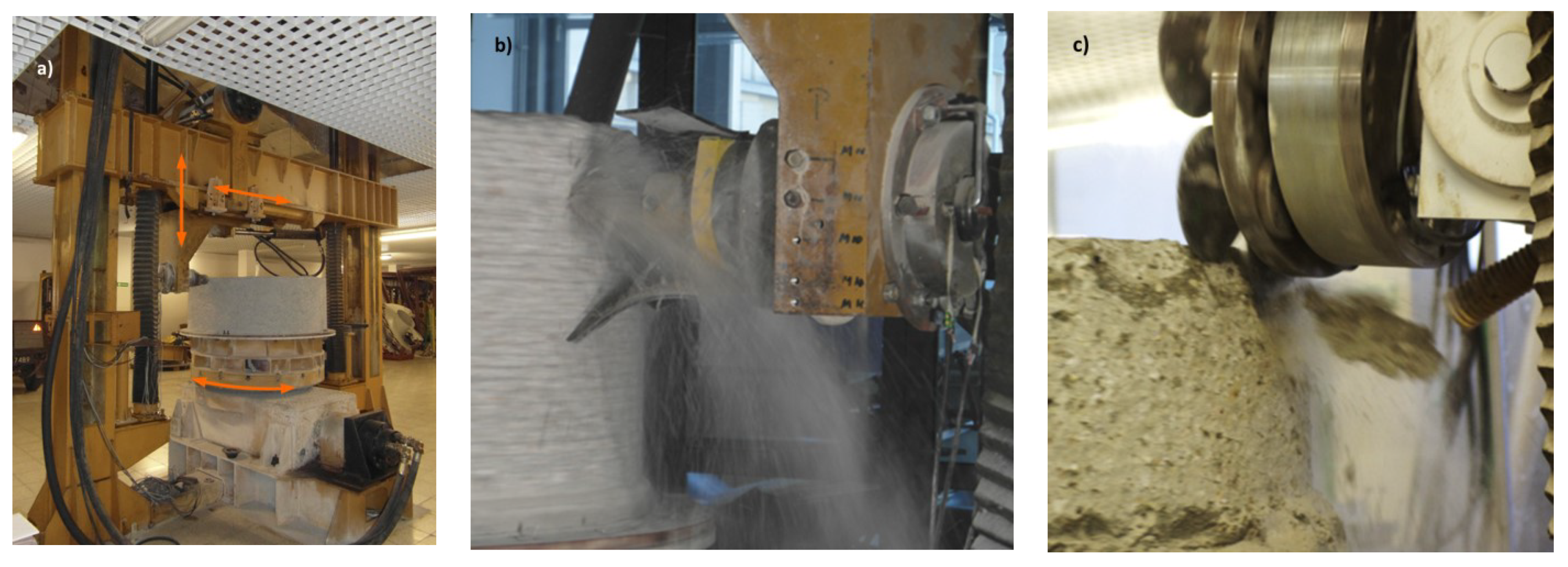
The stand presented in Figure 15 is another test bench used at AGH, which has extensive research capabilities. The stand has a characteristic design and principle of operation. The centrally installed cylindrical specimen subjected to cutting rotates during testing. A tool or a set of tools cuts the sample from the side or from the top. The stand allows for testing of conical picks and discs through cutting or static pressure. The use of an additional, driven plate enables examination of the process of undercutting. The tool or set of tools moves linearly in two directions. All of the elements are driven by motors and hydraulic actuators. The stand can be used to carry out cutting tests on the top surface of a stationary specimen, which boils down to the same principle of operation as in the case of LCM benches. Due to the cylindrical, rotating sample, an unusual cutting process is obtained. The measurement of torques and forces allows the for investigation of the impact of various parameters and tools on the cutting resistance [39].
This stand has also been used to study the impact of supporting the cutting process with a water jet [20].
The design and principle of operation of the above test benches differs from the previously discussed ones, which have been grouped into specific categories due to common features.
The variety of stands for testing tools and cutter heads and the very process of rock cutting indicates a continued interest in this subject. Testing on benches provides greater research and technical possibilities than testing on machines in real conditions.
4. Conclusions
Mechanical rock mining is widely applied in many industries. To solve the problem of tools’ short service life and the high energy consumption of the process, research in this field is being conducted in many centres around the world. Testing of mining tools in real conditions is rarely performed due to the cost and specificity of this industry. Investigations into the process of rock mining, new mining methods, and new designs and materials for tools require the use of appropriate test benches. Laboratory tests enable the measurement of many quantities that cannot be measured in real conditions.
In this article, the significant advantages, disadvantages, and limitations in the use of individual stands were pointed. Thus, guidelines and recommendations have been developed that are valuable when choosing a stand solution for a specific application. The test benches presented are intended for testing cutting discs and conical picks. Some allow interchangeably testing both types of tools, while others can only be used to test either discs or conical picks. Each stand enables recreation of the mining process in a simplified way. The test bench scale, maximum generated forces, and cutting speeds are the most common simplification. The scale of the stand is mainly connected with its size concerning the actual cutting heads. They usually allow one working tool to be tested at a time. Laboratory stands that enable testing of real-size cutting heads with real rotational speed and feed speed are unique.
The test benches presented are used for various purposes. Typically, the process of rock cohesion destruction or the generated cutting resistance is examined. The resistance generated by different tools and when cutting different materials can be compared. In addition, these test stands allow for examination of various methods of mechanical mining along with their modifications in the form of changed trajectory, introduced oscillations, and the use of liquid jet support or microwaves.
The testing of the rock destruction process in a fundamental scope by pressing the tool into a specimen is frequently used to validate numerical models, where mining processes are simulated using finite or discrete element methods.
The second important aspect is testing the wear rate or the durability of the tools. Discs and picks wear out during operation. Properly designed and manufactured tools wear abrasively. Such tests enable assessment of the abrasive wear resistance of specific materials and coatings. Due to the cutting time needed for tool wear to be measured, test benches with rotating cutting heads are the most effective.
Some test benches enable a broader assessment of the cutting process effects. The grain size of the excavated material or the generated dust is measured very often. Tests are also carried out to assess the tools’ temperature during mining. Another examined aspect related to friction and temperature is the formation of sparks. Vibrations and sound levels can also be measured.
In each case, the influence of individual parameters (e.g., cutting speed and tool geometry) on the aspect subjected to testing is examined.
This article shows that although the rock mining process has been studied for many years, it is still a topical subject. New research is being carried out on an ongoing basis, and new test benches are being created. The conditions that prevail in real conditions limit the possibility of simultaneous measurements; hence, laboratory stands and simulation tests based on the FEM and DEM methods very often provide the only possibility to carry out tests. However, using FEM and DEM methods also requires validation by laboratory tests.
5. Future Directions
The review and analysis conducted conclude that the test benches presented can be successfully used for testing the mining process, where the cutting resistance or the course of the rock destruction process are essential.
Tests of the process carried out on a scaled test bench or for a linear trajectory do not reflect reality. However, the results of such tests can be successfully used to compare different solutions and parameters and to validate computer simulations. In the computer simulation, the same scale, trajectory and, of course, parameters should be kept. However, special care ought to be taken when drawing conclusions on the basis of such studies if these conclusions are to apply to real machines and processes because the scale of the object as well as the trajectory of the tool movement have a significant impact on the process.
Tests on benches with a rotating head allow for measurement of the torque on the cutting head as well as the longitudinal and transverse feed forces. However, there is no information about the load of a single tool. Currently, various methods of wireless transmission of measurement data can be used; hence, it is possible to apply measurement systems on the cutting head to measure forces on the tool. This can be carried out for each or for selected tools. The measuring system can be powered by a battery installed on the rotating head, and the data can be transmitted wirelessly. This will allow full information about the load on the tools during the cutting process to be obtained.
The very important issue of the durability of mining tools is the subject of numerous studies. Currently, the following tests are performed:
- Testing of finished tools in laboratory conditions,
- Testing of ready tools in real conditions,
- Testing of wear rate by mechanical engineering methods.
Testing of finished tools’ wear rate is a very good and effective method, but it is also expensive and time-consuming due to the necessity of making a finished product and conducting tests in conditions that reflect the real ones. Therefore, a limited number of different geometries, materials, or coatings can be observed in this way.
Testing of ready-made tools in real conditions has a number of advantages, but it cannot be used as a research method due to the excessive heterogeneity and isotropic nature of rocks. In addition, tests in real conditions make the work of a mining plant difficult. Such tests are recommended for the proven solutions of tools selected in the earlier stages.
Standard methods of abrasive wear testing applied in mechanical engineering are only valid for the materials and coatings used in mechanical engineering. The process of abrasive wear applies only to the surface and is consistent with the manner of operation of typical structural nodes exposed to abrasive wear. However, it has been proven that these methods are not suitable for testing materials and coatings for mining tools, as the process of surface destruction is different.
Therefore, for testing materials and coatings to select suitable ones for cutting tools, developing a new methodology and test stand is recommended. A methodology for comparative testing of probes (testers) in laboratory conditions should be developed, in a process imitating the abrasive wear that occurs during rock mining. Small probes made of different materials, with different coatings and subjected to specific processes, e.g., thermo-chemical treatment should be compared with each other. Tests should be carried out on an artificial specimen, i.e., concrete with a controlled composition. Thanks to the low time consumption and weight, such probes as well as the tests themselves, will enable quick and cheap testing of dozens of solutions of various materials, coatings, or parameters of a thermo-chemical treatment process.
Using the proposed test bench as well as the other existing and applied test stands, it is recommended to design new tools in the following order:
- Testing of many solutions, various samples on the proposed test bench, ended with the selection of the several best solutions that will be used to produce mining tools. During these tests, cutting resistance is irrelevant.
- Testing of ready-made tools on a laboratory stand ended with the selection of the best solution. During these tests, cutting resistance should be checked in addition to wear rate.
- Testing of a selected solution of a mining tool in real conditions.
Such an approach will significantly increase the scope of the conducted research and will allow for testing of the possibility of using new materials, thermo-chemical processes, or coatings for mining tools on an ongoing basis.
Author Contributions
Ł.B. and W.B., analysis of the literature and the state of knowledge; W.B., introduction; W.B., simple test benches; Ł.B., LCM benches; W.B., rotary benches; Ł.B., other benches; W.B., conclusions; Ł.B., future directions; Ł.B., elaboration of paper. All authors have read and agreed to the published version of the manuscript.
Funding
This research received no external funding.
Institutional Review Board Statement
Not applicable.
Informed Consent Statement
Not applicable.
Data Availability Statement
Data are contained within the article.
Conflicts of Interest
The authors declare no conflict of interest.
References
- Krauze, K.; Bołoz, Ł.; Wydro, T. Mechanized Shaft Sinking System. Arch. Min. Sci. 2018, 63, 891–902. [Google Scholar] [CrossRef]
- Bołoz, Ł. Interpretation of the Results of Mechanical Rock Properties Testing with Respect to Mining Methods. AMS 2020, 25, 81–93. [Google Scholar] [CrossRef]
- Kotwica, K. Asymmetrical Mini Disk Tools—Possibilities of Use and Directions for Further Development. New Trends Prod. Eng. 2019, 2, 223–232. [Google Scholar] [CrossRef] [Green Version]
- Krzysztof, K.; Piotr, M. Methods of Mechanical Mining of Compact-Rock—A Comparison of Efficiency and Energy Consumption. Energies 2019, 12, 3562. [Google Scholar] [CrossRef] [Green Version]
- Biały, W.; Fries, J.; Galecki, G. Determination of Coal Cutting Forces Using the Cutting Head of POU-BW/01-WAP Device. Multidiscip. Asp. Prod. Eng. 2021, 4, 281–289. [Google Scholar] [CrossRef]
- Biały, W. Determination of Workloads in Cutting Head of Longwall Tumble Heading Machine. Manag. Syst. Prod. Eng. 2016, 21, 45–54. [Google Scholar] [CrossRef]
- Bołoz, Ł.; Krauze, K. Ability to Mill Rocks in Open-Pit Mining. In Proceedings of the 18th International Multidisciplinary Scientific GeoConference SGEM 2018, Albena, Bulgaria, 20 June 2018. [Google Scholar]
- Bołoz, Ł.; Krauze, K.; Kubín, T. Mechanisation of Longwall Extraction of Hard and Abrasive Rocks. Multidiscip. Asp. Prod. Eng. 2018, 1, 331–337. [Google Scholar] [CrossRef] [Green Version]
- Krauze, K.; Bołoz, Ł.; Wydro, T. Parametric Factors for the Tangential-Rotary Picks Quality Assessment. Arch. Min. Sci. 2015, 60, 265–281. [Google Scholar] [CrossRef]
- Dehkhoda, S.; Detournay, E. Rock Cutting Experiments with an Actuated Disc. Rock Mech. Rock Eng. 2019, 52, 3443–3458. [Google Scholar] [CrossRef]
- Gajewski, J.; Podgórski, J.; Jonak, J.; Szkudlarek, Z. Numerical Simulation of Brittle Rock Loosening during Mining Process. Comput. Mater. Sci. 2008, 43, 115–118. [Google Scholar] [CrossRef]
- Krauze, K.; Mucha, K.; Wydro, T.; Pieczora, E. Functional and Operational Requirements to Be Fulfilled by Conical Picks Regarding Their Wear Rate and Investment Costs. Energies 2021, 14, 3696. [Google Scholar] [CrossRef]
- Krauze, K.; Bołoz, Ł.; Wydro, T.; Mucha, K. Durability Testing of Tangential-Rotary Picks Made of Different Materials. Min. Inform. Autom. Electr. Eng. 2017, 1, 68. [Google Scholar] [CrossRef]
- Zhang, Z.; Zhang, K.; Dong, W.; Zhang, B. Study of Rock-Cutting Process by Disc Cutters in Mixed Ground Based on Three-Dimensional Particle Flow Model. Rock Mech. Rock Eng. 2020, 53, 3485–3506. [Google Scholar] [CrossRef]
- Li, H.S.; Liu, S.Y.; Xu, P.P. Numerical Simulation on Interaction Stress Analysis of Rock with Conical Picks. Tunn. Undergr. Space Technol. 2019, 85, 231–242. [Google Scholar] [CrossRef]
- Slouka, S.; Brune, J.; Rostami, J.; Tsai, C.; Sidrow, E. Characterization of Respirable Dust Generated from Full Scale Cutting Tests in Limestone with Conical Picks at Three Stages of Wear. Minerals 2022, 12, 930. [Google Scholar] [CrossRef]
- Bołoz, Ł.; Kalukiewicz, A. Machines for Mechanical Mining of Hardly Workable and Abrasive Rocks. Multidiscip. Asp. Prod. Eng. 2020, 3, 150–160. [Google Scholar] [CrossRef]
- Vogt, D. A Review of Rock Cutting for Underground Mining: Past, Present, and Future. J. South. Afr. Inst. Min. Metall. 2016, 116, 1011–1026. [Google Scholar] [CrossRef] [Green Version]
- Stoxreiter, T.; Martin, A.; Teza, D.; Galler, R. Hard Rock Cutting with High Pressure Jets in Various Ambient Pressure Regimes. Int. J. Rock Mech. Min. Sci. 2018, 108, 179–188. [Google Scholar] [CrossRef]
- Kotwica, K. Hard Rock Mining Using Disk Tools Supported by High-Pressure Water Jets in the Aspect of Reducing Energy Consumption. Energies 2021, 14, 2595. [Google Scholar] [CrossRef]
- Zhang, J.; Li, Y.; Zhang, Y.; Yang, F.; Liang, C.; Tan, S. Using a High-Pressure Water Jet-Assisted Tunnel Boring Machine to Break Rock. Adv. Mech. Eng. 2020, 12, 168781402096229. [Google Scholar] [CrossRef]
- Ramezanzadeh, A.; Hood, M. A State-of-the-Art Review of Mechanical Rock Excavation Technologies. J. Min. Environ. 2010, 1, 29–39. [Google Scholar] [CrossRef]
- Sifferlinger, N.A.; Hartlieb, P.; Moser, P. The Importance of Research on Alternative and Hybrid Rock Extraction Methods. Berg Huettenmaenn Mon. 2017, 162, 58–66. [Google Scholar] [CrossRef] [Green Version]
- Bołoz, Ł. Directions for Increasing Conical Picks’ Durability. New Trends Prod. Eng. 2019, 2, 277–286. [Google Scholar] [CrossRef] [Green Version]
- Shandong Techgong Geotechnical Engineering Equipment Co., Ltd. Available online: https://www.techgong.com (accessed on 19 November 2022).
- Bołoz, Ł. Conical Picks for Undeground Mining. New Trends Prod. Eng. 2020, 3, 221–230. [Google Scholar] [CrossRef]
- Bołoz, Ł.; Kalukiewicz, A.; Galecki, G.; Romanyshyn, L.; Romanyshyn, T.; Giménez, R.B. Conical Pick Production Process. New Trends Prod. Eng. 2020, 3, 231–240. [Google Scholar] [CrossRef]
- Gospodarczyk, P.; Kotwica, K.; Stopka, G. A New Generation Mining Head with Disc Tool of Complex Trajectory. Arch. Min. Sci. 2013, 58, 985–1006. [Google Scholar] [CrossRef] [Green Version]
- Dewangan, S.; Chattopadhyaya, S. Characterization of Wear Mechanisms in Distorted Conical Picks After Coal Cutting. Rock Mech. Rock Eng. 2016, 49, 225–242. [Google Scholar] [CrossRef]
- Bołoz, Ł. Results of a Study on the Quality of Conical Picks for Public Procurement Purposes. New Trends Prod. Eng. 2018, 1, 687–693. [Google Scholar] [CrossRef] [Green Version]
- Bołoz, Ł.; Krauze, K. Disc Unit Dedicated to Mine Abrasive Rocks and in Particular Copper Ores. In Proceedings of the 18th International Multidisciplinary Scientific GeoConference SGEM 2018, Albena, Bulgaria, 20 June 2018. [Google Scholar]
- The Next Revolution in EPB Cutters—New Cutter Designs Make an Impression in Mixed Ground. Available online: https://www.tunnel-online.info/en/artikel/tunnel_the_next_revolution_in_epb_cutters_new_cutter_designs_make_an_impression_1734178.html (accessed on 19 November 2022).
- Bołoz, Ł.; Midor, K. Process Innovations in the Mining Industry and the Effects of Their Implementation Presented on the Example of Longwall Milling Heads. AMS 2018, 23, 81–93. [Google Scholar]
- Biały, W. Innovative Solutions Applied in Tools for Determining Coal Mechanical Proprerties. Manag. Syst. Prod. Eng. 2015, 4, 202–209. [Google Scholar] [CrossRef]
- Wang, X.; Su, O. Specific Energy Analysis of Rock Cutting Based on Fracture Mechanics: A Case Study Using a Conical Pick on Sandstone. Eng. Fract. Mech. 2019, 213, 197–205. [Google Scholar] [CrossRef]
- Lin, Q.; Cao, P.; Cao, R. Experimental Investigation of Jointed Rock Breaking under a Disc Cutter with Different Confining Stresses. Comptes Rendus Mécanique 2018, 346, 833–843. [Google Scholar] [CrossRef]
- Jaime, M.C.; Zhou, Y.; Lin, J.-S.; Gamwo, I.K. Finite Element Modeling of Rock Cutting and Its Fragmentation Process. Int. J. Rock Mech. Min. Sci. 2015, 80, 137–146. [Google Scholar] [CrossRef] [Green Version]
- Stopka, G. Laboratory Research on the Influence of Selected Technological Parameters on Cutting Forces during Hard Rock Mining with Asymmetric Disc Tools. AMS 2020, 25, 94–104. [Google Scholar] [CrossRef]
- Kotwica, K.; Stopka, G.; Prostański, D. Study and Application of Asymmetrical Disk Tools for Hard Rock Mining. Energies 2021, 14, 1826. [Google Scholar] [CrossRef]
- Stopka, G. Modelling of Rock Cutting with Asymmetrical Disc Tool Using Discrete-Element Method (DEM). Rock Mech. Rock Eng. 2021, 54, 6265–6279. [Google Scholar] [CrossRef]
- Kang, H.; Cho, J.-W.; Park, J.-Y.; Jang, J.-S.; Kim, J.-H.; Kim, K.-W.; Rostami, J.; Lee, J.-W. A New Linear Cutting Machine for Assessing the Rock-Cutting Performance of a Pick Cutter. Int. J. Rock Mech. Min. Sci. 2016, 88, 129–136. [Google Scholar] [CrossRef]
- Dewangan, S.; Ponsingh Jomy, A.; Ashwin Nethran, G. Modelling and Simulation of Stress Generation and Temperature Distribution in Conical Picks during Linear Coal-Cutting Process. Mater. Today Proc. 2022, 62, 1458–1464. [Google Scholar] [CrossRef]
- Balci, C.; Bilgin, N. Correlative Study of Linear Small and Full-Scale Rock Cutting Tests to Select Mechanized Excavation Machines. Int. J. Rock Mech. Min. Sci. 2007, 44, 468–476. [Google Scholar] [CrossRef]
- Cho, J.-W.; Jeon, S.; Jeong, H.-Y.; Chang, S.-H. Evaluation of Cutting Efficiency during TBM Disc Cutter Excavation within a Korean Granitic Rock Using Linear-Cutting-Machine Testing and Photogrammetric Measurement. Tunn. Undergr. Space Technol. 2013, 35, 37–54. [Google Scholar] [CrossRef]
- Zhang, X.; Xia, Y.; Tan, Q.; Wu, D. Comparison Study on the Rock Cutting Characteristics of Disc Cutter under Free-Face-Assisted and Conventional Cutting Methods. KSCE J. Civ. Eng. 2018, 22, 4155–4162. [Google Scholar] [CrossRef]
- Copur, H.; Bilgin, N.; Balci, C.; Tumac, D.; Avunduk, E. Effects of Different Cutting Patterns and Experimental Conditions on the Performance of a Conical Drag Tool. Rock Mech. Rock Eng. 2017, 50, 1585–1609. [Google Scholar] [CrossRef]
- Wang, S.; Sun, L.; Li, X.; Zhou, J.; Du, K.; Wang, S.; Khandelwal, M. Experimental Investigation and Theoretical Analysis of Indentations on Cuboid Hard Rock Using a Conical Pick under Uniaxial Lateral Stress. Geomech. Geophys. Geo-Energy Geo-Resour. 2022, 8, 34. [Google Scholar] [CrossRef]
- Liu, Q.; Pan, Y.; Liu, J.; Kong, X.; Shi, K. Comparison and Discussion on Fragmentation Behavior of Soft Rock in Multi-Indentation Tests by a Single TBM Disc Cutter. Tunn. Undergr. Space Technol. 2016, 57, 151–161. [Google Scholar] [CrossRef]
- Pan, Y.; Liu, Q.; Liu, J.; Huang, X.; Liu, Q.; Peng, X. Comparison between Experimental and Semi-Theoretical Disc Cutter Cutting Forces: Implications for Frame Stiffness of the Linear Cutting Machine. Arab. J. Geosci. 2018, 11, 266. [Google Scholar] [CrossRef]
- Bilgin, N.; Demircin, M.A.; Copur, H.; Balci, C.; Tuncdemir, H.; Akcin, N. Dominant Rock Properties Affecting the Performance of Conical Picks and the Comparison of Some Experimental and Theoretical Results. Int. J. Rock Mech. Min. Sci. 2006, 43, 139–156. [Google Scholar] [CrossRef]
- Yasar, S.; Yilmaz, A.O. Drag Pick Cutting Tests: A Comparison between Experimental and Theoretical Results. J. Rock Mech. Geotech. Eng. 2018, 10, 893–906. [Google Scholar] [CrossRef]
- Xia, Y.; Shi, Y.; Lin, L.; Zhang, Y.; Tan, Q.; Yang, Y. Experimental Evaluation of Fragments from TBM Disc Cutting under Different Load Cases. Period. Polytech. Civ. Eng. 2018, 62, 746–756. [Google Scholar] [CrossRef] [Green Version]
- Pan, Y.; Liu, Q.; Kong, X.; Liu, J.; Peng, X.; Liu, Q. Full-Scale Linear Cutting Test in Chongqing Sandstone and the Comparison with Field TBM Excavation Performance. Acta Geotech. 2019, 14, 1249–1268. [Google Scholar] [CrossRef]
- Jackson, E.; Clarke, D. Minimole: Development and Field Testing of a Narrow—Vein Hard Rock Mechanical Mining Machine; SME: Chandler, AZ, USA, 2007. [Google Scholar]
- Xiaohui, L.; Songyong, L.; Xinxia, C.; Ping, T. Interference Model of Conical Pick in Cutting Process. J. Vibroengineering 2014, 16, 103–115. [Google Scholar]
- Wang, Z.; Zeng, Q.; Wan, L.; Lu, Z.; Wang, H. Investigation of the Influence of Cutting Parameters on Conical Pick Cutting Performance and Rock Damage. Machines 2022, 10, 1034. [Google Scholar] [CrossRef]
- Shao, W.; Li, X.; Sun, Y.; Huang, H. Parametric Study of Rock Cutting with SMART∗CUT Picks. Tunn. Undergr. Space Technol. 2017, 61, 134–144. [Google Scholar] [CrossRef]
- Li, B.; Zhang, B.; Hu, M.; Liu, B.; Cao, W.; Xu, B. Full-Scale Linear Cutting Tests to Study the Influence of Pre-Groove Depth on Rock-Cutting Performance by TBM Disc Cutter. Tunn. Undergr. Space Technol. 2022, 122, 104366. [Google Scholar] [CrossRef]
- Liu, X.; Liu, S.; Li, L.; Cui, X. Experiment on Conical Pick Cutting Rock Material Assisted with Front and Rear Water Jet. Adv. Mater. Sci. Eng. 2015, 2015, 506579. [Google Scholar] [CrossRef] [Green Version]
- Lu, G.; Zhou, J.; Zhang, L.; Gao, W. Experimental Investigation on the Influence of Microwave Exposure on the Cutting Performance of TBM Disc Cutter Cutting of Hard Rocks. Results Eng. 2021, 12, 100285. [Google Scholar] [CrossRef]
- Ghamgosar, M.; Erarslan, N. A Numerical Study on Oscillating Disc Cutting (ODC) Technology for Hard Rock Cutting. In Proceedings of the 13th ISRM International Congress of Rock Mechanics, Montreal, QC, Canada, 10–13 May 2015. [Google Scholar] [CrossRef]
- Rock Cutting Equipment Actuated Undercutting Disc Test-Unit Dubbed as Wobble. Available online: https://research.csiro.au/hardrockcutting/facilities/actuated-undercutting-disc-test-unit-wobble (accessed on 21 November 2022).
- Kim, H.; Nam, K.; Kyeon, T.; Rehman, H.; Yoo, H. Analysis of the Effect of the Tool Shape on the Performance of Pre-Cutting Machines during Tunneling Using Linear Cutting Tests. Appl. Sci. 2022, 12, 4489. [Google Scholar] [CrossRef]
- Liu, S.; Du, C.; Cui, X. Research on the Cutting Force of a Pick. Min. Sci. Technol. 2009, 19, 514–517. [Google Scholar] [CrossRef]
- Liu, X.; Liu, S.; Tang, P. Coal Fragment Size Model in Cutting Process. Powder Technol. 2015, 272, 282–289. [Google Scholar] [CrossRef]
- Liu, S.; Ji, H.; Liu, X.; Jiang, H. Experimental Research on Wear of Conical Pick Interacting with Coal-Rock. Eng. Fail. Anal. 2017, 74, 172–187. [Google Scholar] [CrossRef]
- Fu, L.; Du, C.; Li, J.; Zheng, K. Influence of Pick Working Angle on Cutting Performance of Auger Miner’s Aiguille. Adv. Mech. Eng. 2015, 7, 168781401558542. [Google Scholar] [CrossRef] [Green Version]
- Gajewski, J.; Jedliński, Ł.; Jonak, J. Classification of Wear Level of Mining Tools with the Use of Fuzzy Neural Network. Tunn. Undergr. Space Technol. 2013, 35, 30–36. [Google Scholar] [CrossRef]
- Krauze, K.; Bołoz, Ł.; Wydro, T.; Mucha, K. Investigations into the Wear Rate of Conical Picks with Abrasion-Resistant Coatings in Laboratory Conditions. IOP Conf. Ser. Mater. Sci. Eng. 2019, 679, 012012. [Google Scholar] [CrossRef]
- Bołoz, Ł.; Midor, K. The Procedure of Choosing an Optimal Offer for a Conical Pick as an Element of Realizing the Sustainable Development Concept in Mining Enterprises. AMS 2019, 24, 140–150. [Google Scholar]
- Cheluszka, P. Optimization of the Cutting Process Parameters to Ensure High Efficiency of Drilling Tunnels and Use the Technical Potential of the Boom-Type Roadheader. Energies 2020, 13, 6597. [Google Scholar] [CrossRef]
- Krauze, K.; Bołoz, Ł.; Mucha, K.; Rożenek, Z. Badania Laboratoryjne Określające Wpływ Zużycia Ściernego Noży Styczno-Obrotowych Na Opory Urabiania. In Mechanizacja, Automatyzacja i Robotyzacja w Górnictwie; Centrum Badań i Dozoru Górnictwa Podziemnego Sp. z o.o.: Lędziny, Poland, 2017; Volume 2. [Google Scholar]
Figure 1.
Cutting tools: (a). conical picks of longwall shearers, (b). conical picks of road headers, (c). conical picks of salt mining machines, (d). conical picks of concrete milling machines, (e). conical picks of milling machines for asphalt road surfaces, (f). symmetrical discs, (g). asymmetric double discs, and h. reinforced discs (a–e) [9], (g–h) [25]).

Figure 2.
Examples of mining machines with conical picks and discs [17]: (a). ICUTROC road header produced by Sandvik and (b). Epiroc Mobile Miner 22H.
Figure 2.
Examples of mining machines with conical picks and discs [17]: (a). ICUTROC road header produced by Sandvik and (b). Epiroc Mobile Miner 22H.

Figure 3.
Mining methods based on the use of conical picks and discs: (a). cutting [29], (b). static pressure [4], and (c). undercutting [28] (D—disc diameter, α—disc angle, t1—cutting depth, t—cutting spacing, Pb—side force, Pd—normal force).
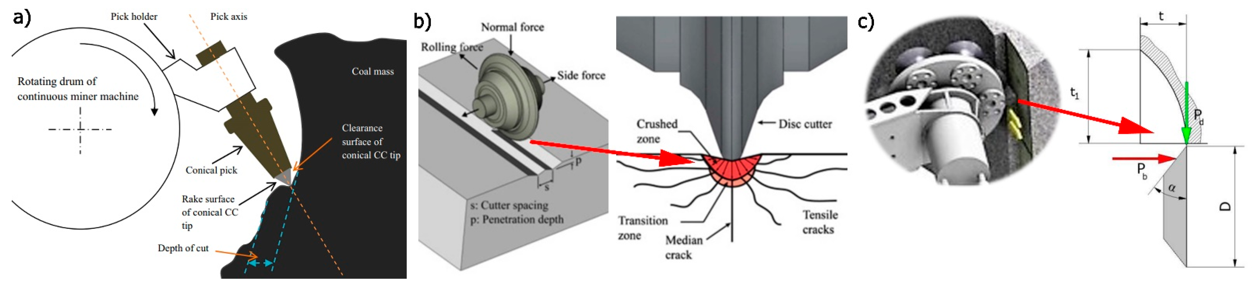
Figure 4.
Examples of excessively worn tools: (a–c). conical picks (the shape of the new pick has been marked in colour) [30], (d). symmetrical disk [32], and (e). asymmetric disk [31].

Figure 5.
Laboratory tests of rock chipping with a conical pick for different distances from the sample edge [35]: (a). general view of pick and rock, (b). experimental model, (c). exemplary rock chips.
Figure 5.
Laboratory tests of rock chipping with a conical pick for different distances from the sample edge [35]: (a). general view of pick and rock, (b). experimental model, (c). exemplary rock chips.
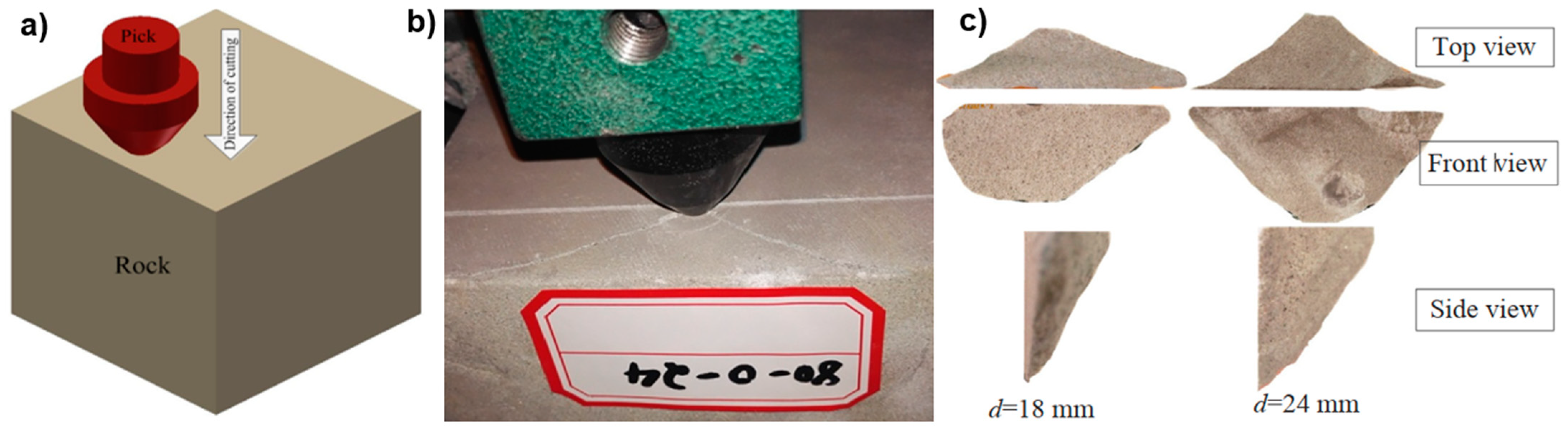
Figure 6.
Comparison of the course of face destruction conducted by the FEM method and on a laboratory stand [37]: (a). FEM results, (b). laboratory tests (frame from high speed camera).
Figure 6.
Comparison of the course of face destruction conducted by the FEM method and on a laboratory stand [37]: (a). FEM results, (b). laboratory tests (frame from high speed camera).

Figure 7.
Laboratory and DEM tests of the process of chipping the face with a disc tool [38,39,40]: (a). test bench with rock and disc, (b). chip after test, (c). DEM results (top and side view).

Figure 8.
LCM stand for testing picks and discs [16].
Figure 8.
LCM stand for testing picks and discs [16].

Figure 9.
Compact LCM bench for testing picks [41].
Figure 9.
Compact LCM bench for testing picks [41].
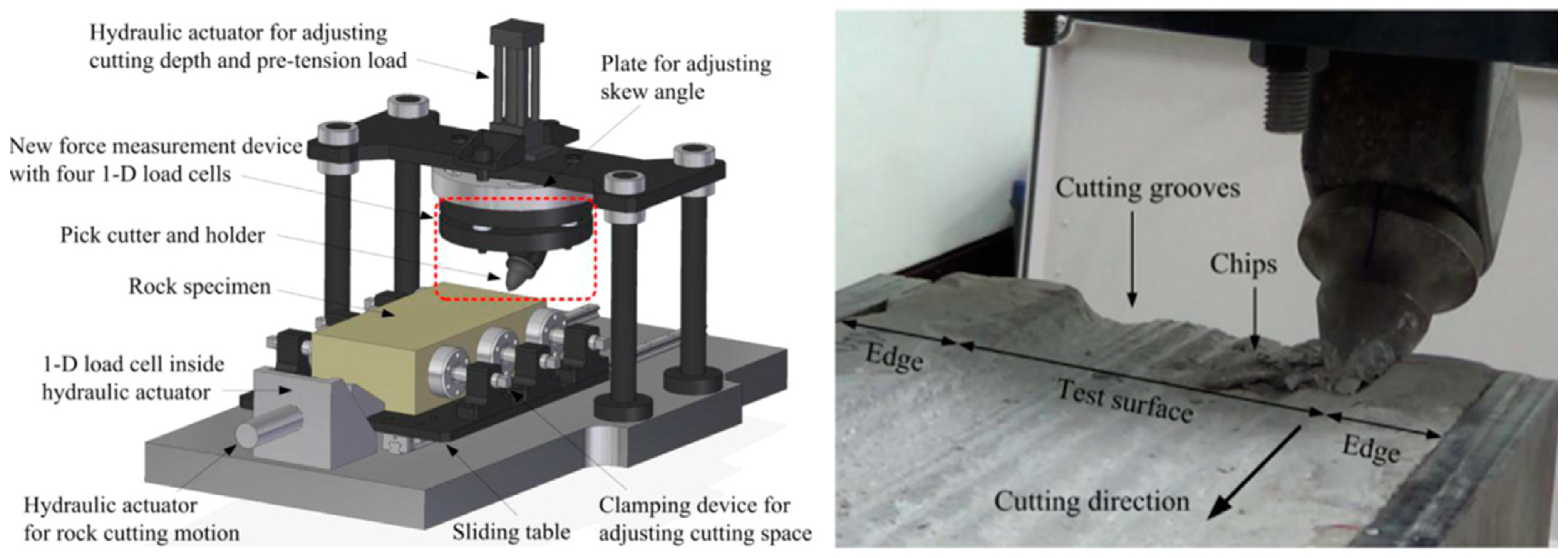
Figure 10.
Electrically-driven LCM test bench [63].
Figure 10.
Electrically-driven LCM test bench [63].
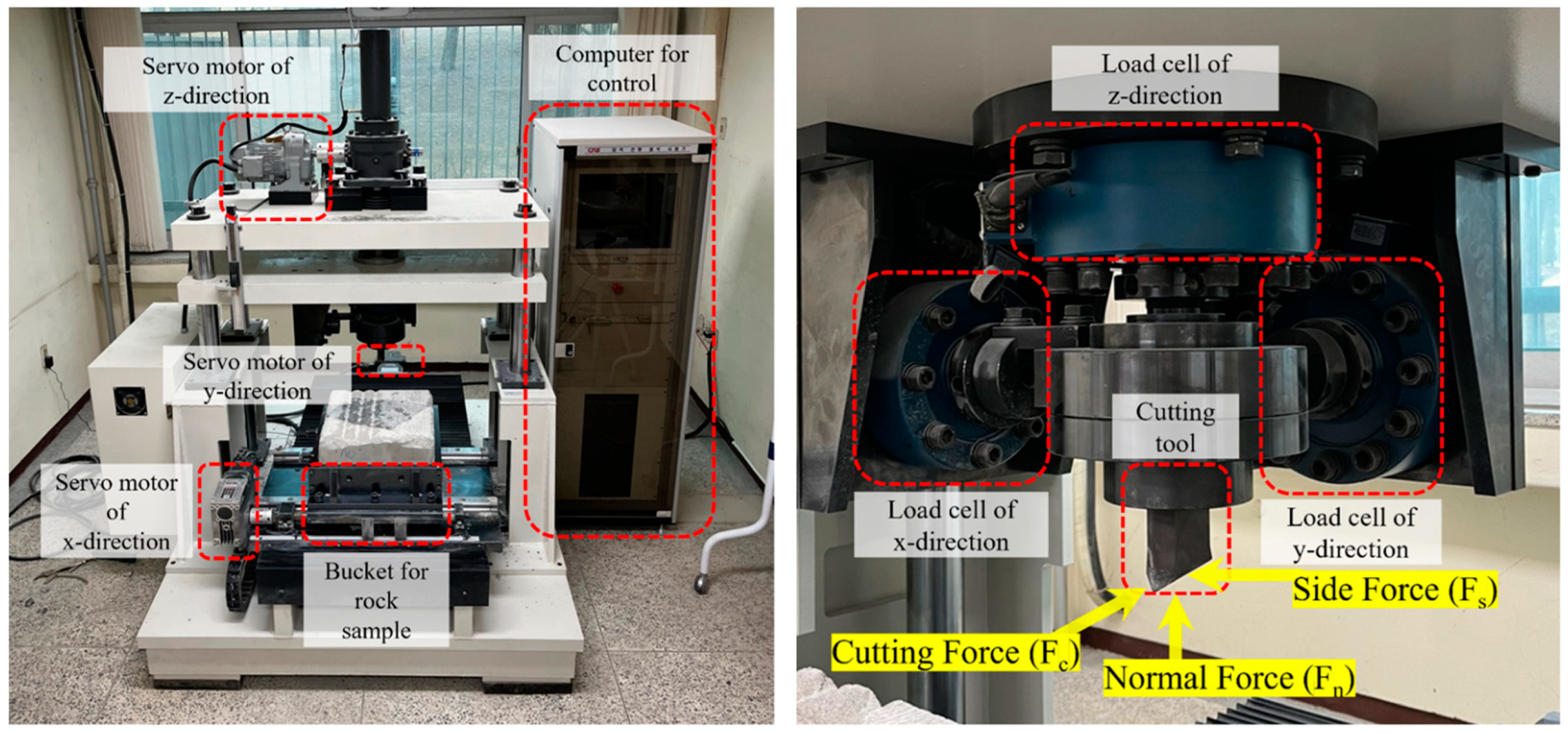
Figure 11.
Revolving cutting bench at the CUMT [65].
Figure 11.
Revolving cutting bench at the CUMT [65].

Figure 12.
Full-size bench for testing the cutting process: (a). measuring cabin, (b). the test plate with a sample, (c). 250 kW drive system, (d). disc cutter head, and (e). cutting with a disc cutter head (a–c) [69], (d,e) [31].

Figure 13.
Bench with a rotating cutter head placed on an arm for testing discs [39].
Figure 13.
Bench with a rotating cutter head placed on an arm for testing discs [39].

Figure 14.
Arm-equipped stand for testing single tools [72].
Figure 14.
Arm-equipped stand for testing single tools [72].
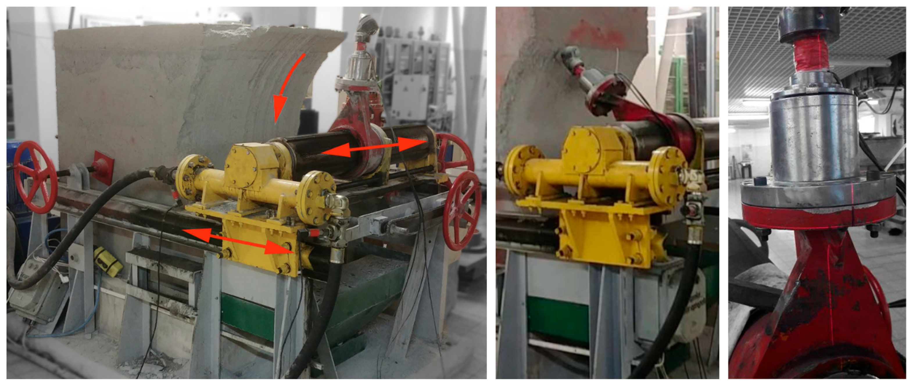
Figure 15.
Stand for testing conical picks and discs: (a). general view of the stand, (b). the testing of a conical pick, and (c). the testing of a driven plate with discs [39].
Figure 15.
Stand for testing conical picks and discs: (a). general view of the stand, (b). the testing of a conical pick, and (c). the testing of a driven plate with discs [39].
Disclaimer/Publisher’s Note: The statements, opinions and data contained in all publications are solely those of the individual author(s) and contributor(s) and not of MDPI and/or the editor(s). MDPI and/or the editor(s) disclaim responsibility for any injury to people or property resulting from any ideas, methods, instructions or products referred to in the content. |
© 2022 by the authors. Licensee MDPI, Basel, Switzerland. This article is an open access article distributed under the terms and conditions of the Creative Commons Attribution (CC BY) license (https://creativecommons.org/licenses/by/4.0/).
Share and Cite
MDPI and ACS Style
Bołoz, Ł.; Biały, W. Methods and Test Benches for Cutting Tools Testing—A Review. Energies 2023, 16, 445. https://doi.org/10.3390/en16010445
AMA Style
Bołoz Ł, Biały W. Methods and Test Benches for Cutting Tools Testing—A Review. Energies. 2023; 16(1):445. https://doi.org/10.3390/en16010445
Chicago/Turabian StyleBołoz, Łukasz, and Witold Biały. 2023. "Methods and Test Benches for Cutting Tools Testing—A Review" Energies 16, no. 1: 445. https://doi.org/10.3390/en16010445
Note that from the first issue of 2016, this journal uses article numbers instead of page numbers. See further details here.