Article

Dynamic Simulation of Partial Load Operation of an Organic Rankine Cycle with Two Parallel Expanders

by
Michael Chukwuemeka Ekwonu
1,
Mirae Kim
1,†,
Binqi Chen
2,†,
Muhammad Tauseef Nasir
1 and
Kyung Chun Kim
1,*
1
School of Mechanical Engineering, Eco-Friendly Smart Ship Parts Technology Innovation Center, Pusan National University, Busan 46241, Republic of Korea
2
School of Aeronautics and Astronautics, University of Electronic Science and Technology of China, Chengdu 611730, China
*
Author to whom correspondence should be addressed.
These authors contributed equally to this work.
Energies 2023, 16(1), 519; https://doi.org/10.3390/en16010519
Submission received: 15 November 2022 / Revised: 28 December 2022 / Accepted: 28 December 2022 / Published: 3 January 2023
(This article belongs to the Section J: Thermal Management)

Abstract

:
The parallel expander ORC system is one of the solutions for providing an additional power output by improving the partial-load performance of an ORC. The parallel expander system corresponds to partial-load conditions by switching between various combinations of the expanders. During this process, the dynamic behavior occurs, which have not been characterized well in the open literature according to the best of the authors’ knowledge. In this study, we developed a dynamic modeling of an ORC system using dual expanders (DE-ORC) to study the dynamic responses during its mode changes. System components were simulated using an open-source library of ThermoCycle written in Modelica language. For each component, empirical parameters were implemented based on the experimental results. Furthermore, during the mode change that involved going from dual expander mode to singular expander mode, and to prevent the formation of the droplet in the expanders, a control strategy was proposed and simulated. The strategy involved lowering of the mass flow rate and then shifting the mode. Several timings between flow rate lowering and shifting the mode were analyzed, and the optimum shifting time was found to be in between 40 to 50 s.

1. Introduction

The thermal efficiency plays an important role in the competitiveness of the energy intensive industries. Therefore, various technologies have been proposed, developed and applied to enhance the efficiency [1]. Moreover, considering the waste heat released from the European industrial sectors, approximately, 30% are reported to present at temperature below 200 °C, and around 25% were reported to be in between 200 °C to 500 °C [2]. Another potential waste heat source is the exhaust from the cars, buses, trucks, and ships [3,4]. The temperature in this range can be harnessed by using the organic Rankine cycle (ORC) technology in a relatively efficient and economical way compared to other devices [5].
The ORC uses organic compounds as its working fluids which enables the exploitation of the low-grade heat from the above-mentioned heat sources at low to medium temperatures, attributing to their low normal boiling temperatures [6]. The ORC has been studied extensively and there are many dimensions along which the research could be conducted. In this regard, the review on the selection of the working fluids was performed by Bao et al. [7]. Similarly, for the working fluids with inclusion of heat sources and cooling media was provided by Qyyum et al. [8]. Moreover, for different architectures for the ORC was provided by Lecompte et al. [9]. Furthermore, regarding the expanders, the review was conducted by Song et al. [10], Imran et al. [11], Zhao et al. [12], and by Pethurajan et al. [13].
It has been reported that the heat source characteristics and system design have a significant impact on ORC systems performance [14]. One of the major concerns pertaining to the ORC operation is the management of fluctuations, particularly related to the vehicular and solar applications. Proper address of this concern is beneficial in order to yield maximum benefit in terms of economics and environment [15]. The issues that can arise from poor handling of the ORC system can be sought from the review performed by Imran et al. [16]. In order to achieve his aim, the dynamic modelling is the prerequisite of developing the appropriate control strategy. In this regard, Wei et al. [17] reported two methodologies for the transient modelling of heat exchangers of an ORC unit. Furthermore, Quoilin et al. [18] developed a dynamic model and presented a control strategy for a variable heat source. Casella et al. [19] presented a component library based on experimentally validated systems. Additionally, in another study, Quolin et al. [20] presented a Modellica library containing the dynamic models. An innovative method for incorporating the dynamic performance of the ORC system into the initial design phase was provided by Pierobon et al. [21]. The thermodynamic cycle computation and system component design were carried out by the numerical model. A multiobjective optimization approach was utilized to find several equally ideal system configurations using the results of these simulations. Other than this, an ORC-based solar thermal power system with an integrated multitube shell and tube thermal storage system was dynamically modelled by Lakhani et al. [22]. Apart from it, a verified transient model of an ORC unit for waste heat utilization in a diesel truck was given by Hustler et al. [23]. The transient behavior of the ORC system is further influenced by the thermal and physical characteristics of the working fluids. According to the rise and settling time, and time constant, Shu et al. [24] evaluated the dynamic response of 14 distinct working fluids. The findings imply that working fluids with low critical temperatures respond more quickly than those with high critical temperatures. The knowledge of the system is based on measurements or prior simulations, and the data-driven models use computational techniques like machine learning [25] or transfer function identification to create models with great computational efficiency [26]. Additionally, a numerical study was conducted by Bamgbopa and Uzgoren [27] investigated the dynamic reaction of the ORC and presented a dynamic model when the thermal energy available changed, either gradually or suddenly. It was shown that changing flow rates assisted preserve steady state operation in addition to increasing thermal efficiency. Similarly, Yousefzadeh and Uzgoren [28] introduced a dynamic numerical model to capture the dynamic response of the ORC for the changes in some key parameters like the working fluid pump and expander speed while still operating with the same heat source condition. In addition to it, Zhou et al. [29] also presented a modelling for a small scale ORC, capable of delivering 4 kW of electricity. The variations of the ORC against the heat source variations were identified and reported.
Expanders are a crucial component of an ORC. In this regard, Zhu et al. [30] conducted experimental findings of the effect of resistive loads on a scroll expander ORC system. The expanders are generally classified into positive displacement type and the turbomachines. Kaczmarczyk [31] presented experimental findings of the expanders parameters and isentropic efficiency of the ORC system operated in series and parallel modes respectively. The maximum efficiency of the system in series and parallel modes are reported. In this regard, Witanowski et al. [32] performed the computational fluid dynamics (CFD) analysis of a single stage axial turbine. The prospects of the turbine at various operational parameters were studied. Kaczmarczyk and Żywica [33] conducted investigation on ORC based scroll expanders under constant electrical load and thermal power of heat source. They reported the maximum efficiency of the systems as 49% with a maximum power generation of 976 W. While Kaczmarczyk et al. [34] reported the performance scroll expanders operated in parallel in a regenerative ORC system. They concluded that scroll expander could be used in a small, distributed cogeneration system.
Considering the efficacy and wide utilization of the models developed and discussed above, a model of similar nature has been attempted for the parallel expander with different capacities (DE-ORC) [35]. The experiments on the ORC rig [35], established and supervised by one of the authors, revealed good practical demonstration to handle the variations in the heat source. The switching between different modes of operations enabled to ensure a better thermal performance of the system as compared to the single expander ORC system. Despite, this, the rigorous dynamic modelling required for such an ORC system remains unexplored, to the best of the authors’ knowledge. Therefore, in this study, the dynamic modeling and its validation is carried out and the discussion has been provided. The results presented thereof can be implemented and utilized for the applications that employ heat sources with variable parameters.

2. Overview of Experimental Setup and Data

The schematic of the experimental setup is shown below in Figure 1a, and the pictorial view of the expanders are shown in Figure 1b. For the experimental inquiry, a PE-ORC system having two scroll expanders of various capacities was developed. The other prominent components were a pump, an evaporator, and a condenser. The open drive expander, altered from an air compressor, manufactured by Kyungwon Machinery Co., LTD, had the upper pressure limit, expansion ratio, and the swept volumes of 10 bar, 4.05, and 25 cm3/rev, respectively. Whereas, the semi hermetic expander, manufactured by Air Squared, Inc., Lafayette, USA, possessed the upper pressure limit of 13.8 bar, expansion ratio of 3.5, and swept volume ratio of 12 cm3/rev. An electromagnetic permanent magnet motor and a torque sensor were both directly coupled to both of the scroll expanders. Furthermore, motor drivers managed the rotational speeds of expanders.
To measure the pressure, the Piezo resistive pressure transmitters with ranges 0–5 bar/0–15 bar with an accuracy of ±0.5% F.S. were used. On the other hand, the mass flow rate was determined using the Coriolis flow meter, was employed having the range from 0–0.305 kg/s, with an accuracy of ±0.1% reading. A Magneto type motor and strain gauges were used to control the rotational speed and measure the torque. The motor had a range of 0–10,000 rpm, and that of the strain gauges was 0–50 Nm. Whereas the accuracy of the rotational speed and the strain gauge was ±1 rpm and ±1 F.S. Apart from it, the k-type thermocouples were used to measure the temperature.
To conduct the experimental study, R245fa was chosen as the working fluid in this investigation because of its suitability for the ORC system in terms of thermodynamic, environmental, and safety parameters. Apart from it, the air infiltration issue into the cycle can be avoided since the condensing pressure of R245fa is similar to the atmospheric pressure at ambient temperature. The working fluid was pumped using a volumetric pump, and the evaporator and condenser were both plate-type heat exchangers. The evaporator received pressured hot water produced by a 150 kW electric heater as a heat source. The condenser received cooling water from an air-cooled chiller that served as a heat sink. The straightforward on/off controls in each component can be used to regulate the temperatures of the heat source and heat sink. Frequency drivers regulate the flow rates of the working fluid, heat source, and heat sink. A Coriolis flow meter was fitted to monitor the mass flow rate of the working fluid, and pressure transmitters, and k-type thermocouples were placed at the inlets and outputs of the major components.
The control modes and the experimental conditions are provided in Table 1 and Table 2.

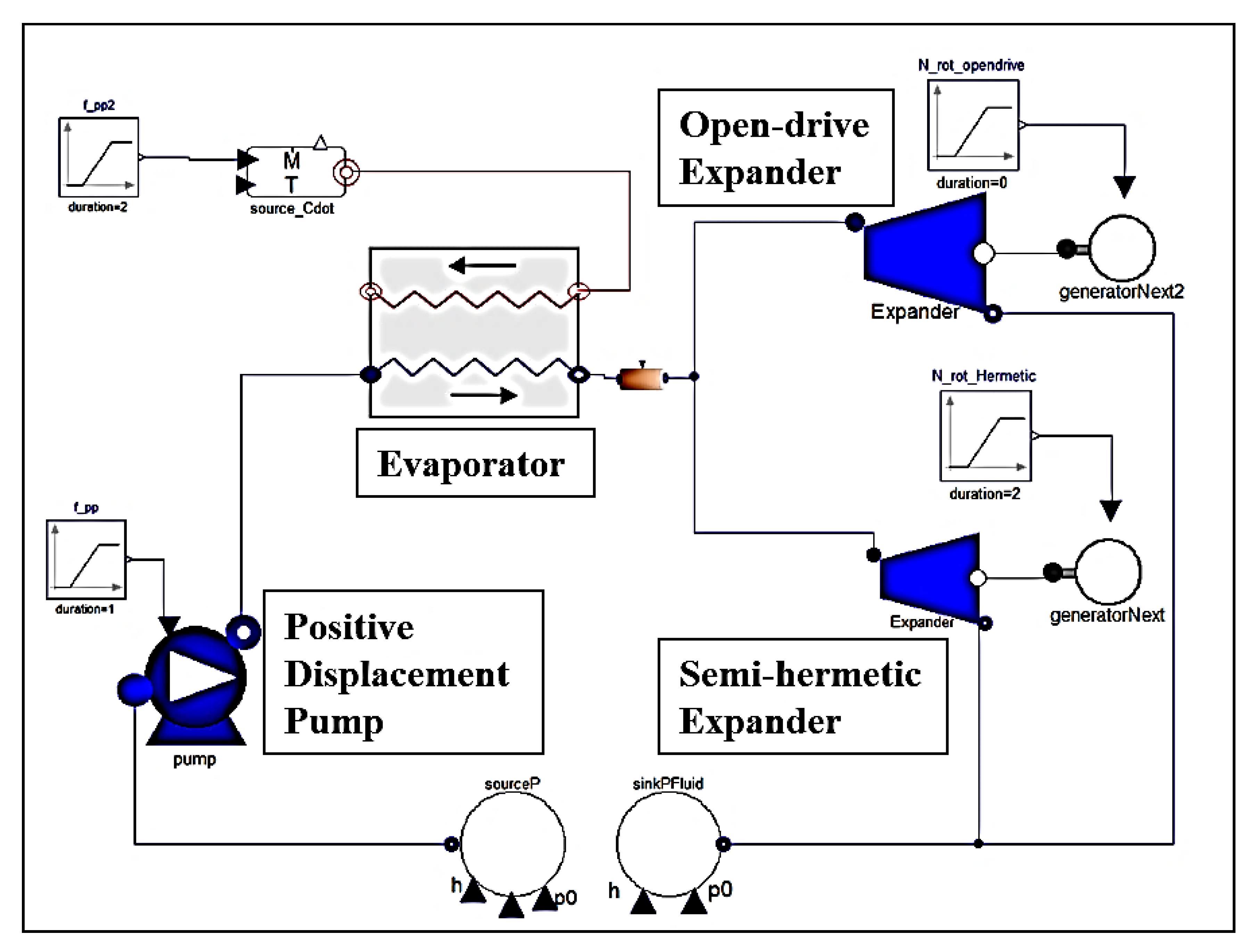
3. Mathematical Modelling

The mathematical modelling of the expander, evaporator, and pump were modeled in the Modelica programming language (Dymola 17). To conduct the dynamic modelling, the open-source library of ThermoCycle was used. ExternalMedia library was used for calculating thermophysical properties of fluids. Figure 2 shows the dynamic modeling of DE-ORC with different capacity expanders.

3.1. Expander

The angular momentum of the expander is negligible because it is small compared to the dynamic response due to the phase change of the heat exchanger [36]. Thus, the steady state model of the scroll expander can be used to study dynamic operating characteristics [18]. For each scroll expander, a model developed by Lemort et al. [37] was used to derive the empirical parameters as shown in Figure 3. This expander model calculates the filling factor, and expander efficiency, η exp considering internal leakage, pressure losses, mechanical losses, and thermal losses. The expander power output was calculated using Equation (1):
W ˙ shaft = m ˙ wf · w shaft · η exp
where W ˙ shaft is the expander shaft power, m ˙ w f is the working fluid mass flow rate, and w shaft is the shaft work. The expander inlet density was calculated using the following Equations (2) and (3):
ρ exp , in = 60 · m ˙ wf / ϕ · V swept · N rot
ϕ = m ˙ wf · v exp , in V ˙ exp , swept
where ρ exp , in is the expander inlet density, V swept is the expander swept volume, v exp , in is the expander inlet specific volume, and N rot is the expander rotational speed. V ˙ exp , swept is the theoretical volume flow rate, and it can be calculated by multiplying the swept volume and the rotating speed.
The filling factor and the expander efficiency are the functions of the rotating speed and the pressure ratio.
ϕ = f N rot , r e x p
η exp = f N rot , r e x p
These functions were simplified to a linear equation to reduce the computing cost as Equations (6)–(9). Figure 4 shows the filling factor and efficiency over different pressure ratios and rotating speeds.
o p = 2.091 0.0008011 · N rot + 0.011 · r e x p + 0.0000001441 · N rot 2 0.000006749 · N rot · r e x p
η exp , op = 95.47 0.08464 · N rot + 135.7 · r e x p + 1.449 × 10 5 · N rot 2 + 0.04124 · N rot · r e x p 43.17 · r e x p 2 7.195 × 10 6 · N rot 2 r e x p 0.004323 · N rot · r e x p 2 + 5.433 · r e x p 3 + 6.301 × 10 7 · N rot 2 · r e x p 2 + 9.576 × 10 5 · N rot · r e x p 3 0.2376 · r e x p 4
s m = 2.87 0.0007611 · N rot + 0.02955 · r e x p + 0.000000091 · N rot 2 0.000004562 · N rot · r e x p
η exp , sm = 74.53 0.08233 · N rot + 59.81 · r e x p + 2.287 × 10 6 · N rot 2 + 0.04543 · N rot · r e x p 34.01 · r e x p 2 4.889 × 10 7 · N rot 2 r e x p 0.008325 · N rot · r e x p 2 + 6.096 · r e x p 3 + 7.662 × 10 8 · N rot 2 · r e x p 2 + 0.0004664 · N rot · r e x p 3 0.3509 · r e x p 4

3.2. Evaporator

The most important factor to consider in dynamic modeling is the heat exchanger, which, unlike the other factors, has the greatest effect on the response time over time in the ORC system due to the phase change of the refrigerant [36]. The dynamic modeling methods of the heat exchanger can be classified into moving boundary (MB) method and finite volume (FV) method. The MB method is a method of dividing the heat exchanger into three parts by dividing the inside of the heat exchanger into the liquid phase, ideal phase and vapor phase. The FV model simplifies the heat exchanger in one dimension, divides the interior into equal volumes. Both models well predicted the dynamic operating characteristic, but MB model overestimated the dynamics when it is used for a small size heat exchanger [38]. In this study, we used FV method to avoid this overestimation as shown in Equation (10) and Figure 5. Table 3 shows the evaporator parameters used for the evaporator.
m ˙ wf , i c p d T wf , i d t = Q ˙ hf , i Q ˙ wf , i

3.3. Pump

The diaphragm pump deforms the diaphragm membrane to draw liquid from the inlet to the pump chamber and to discharge the liquid to the upper discharge pipe. The flow rate of the diaphragm pump is determined by the volume of the inner chamber and the RPM of the pump. The flow rate of the pump is given by the following equation when the temperature and pressure of the fluid at the inlet side of the pump are constant. The pump performance curve, for the modes have been provided in Figure 6.
m ˙ pp = V ˙ su , pp , max v su , pp H z 60

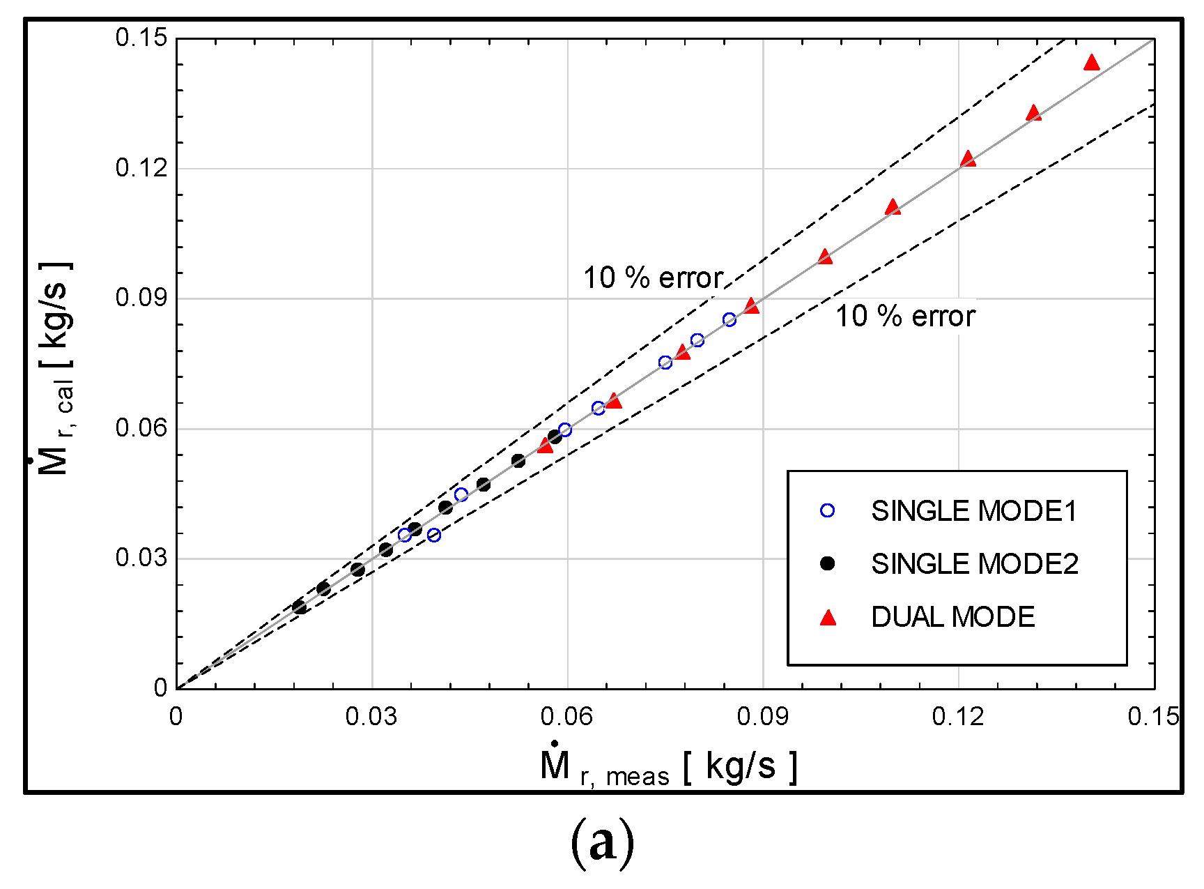
3.4. Model Validation

Figure 7 shows the differences for the working fluid mass flow rate, the expander inlet pressure, the evaporator heat rate, and the expander shaft power. In Figure 7a, the working fluid mass flow rate was within 10% error. In Figure 7b, the expander inlet pressure was also within 10%, however single mode 1 showed lower value in the simulation case. On the other hand, single mode 2 showed higher value in the simulation. In Figure 7c, the shaft power was overestimated. This error has resulted from the simplification of the expander model for dynamic simulation. In Figure 7d, the evaporation heat rate was well predicted within 10% error range.

4. Results and Discussion

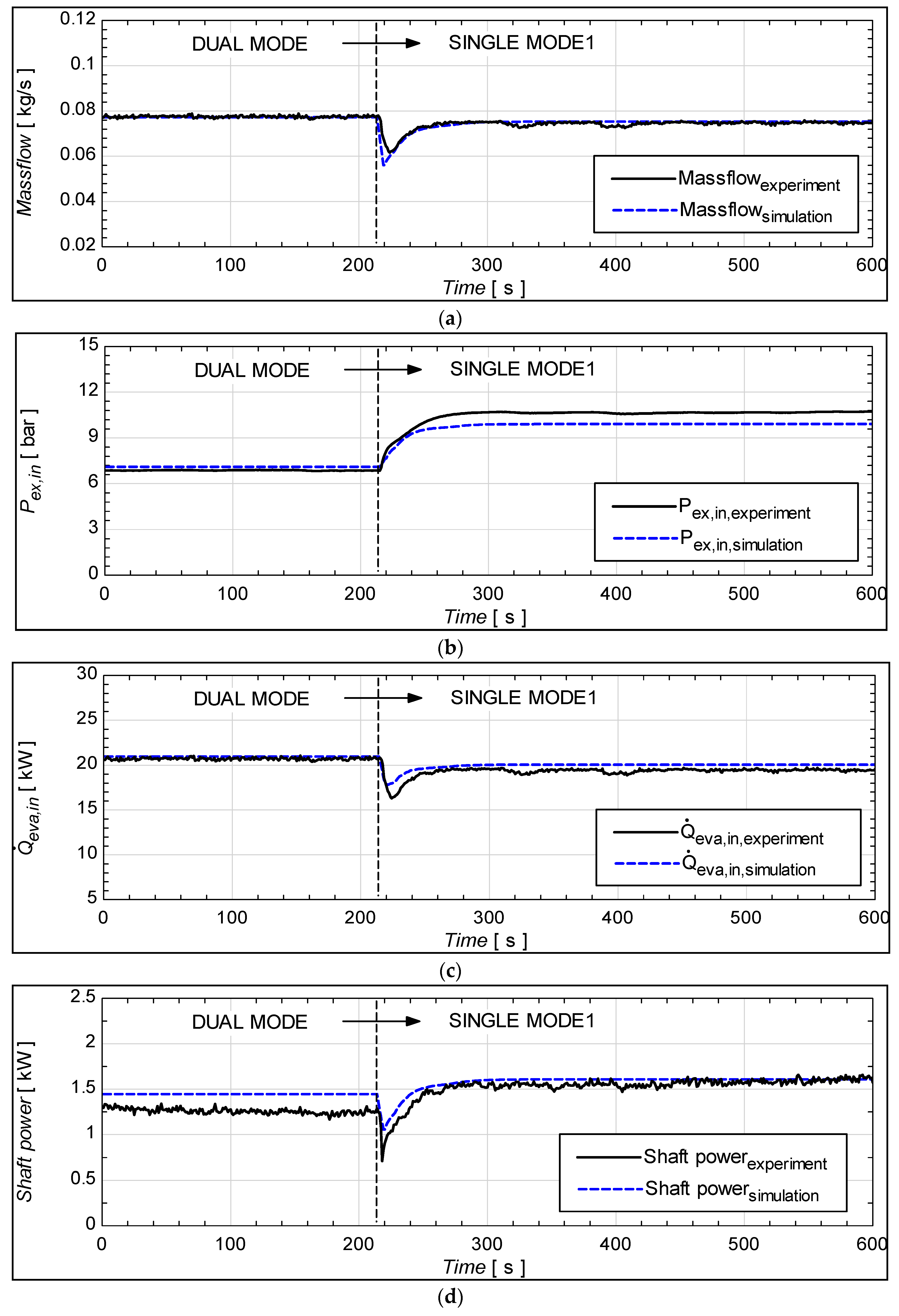
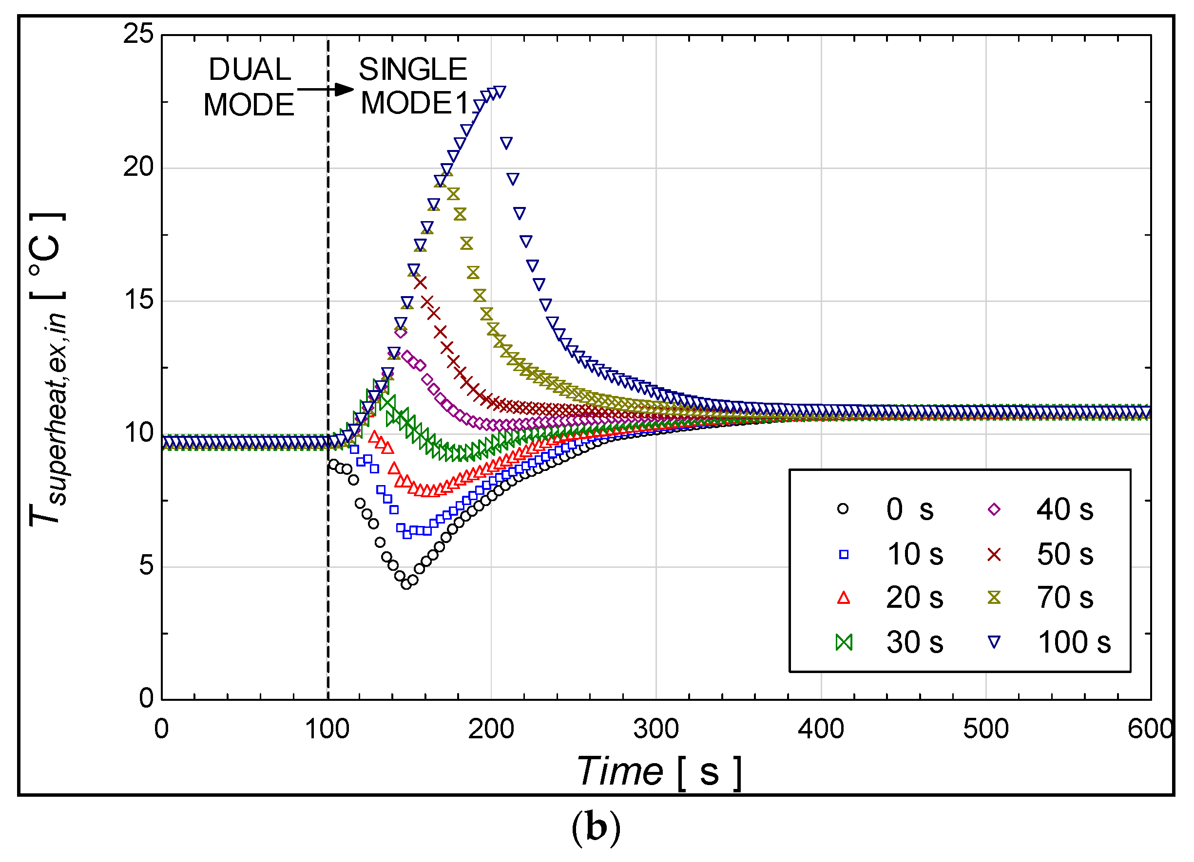
4.1. Mode Change Operation

As shown in Table 1, the ORC system was controlled to change the operating mode. Figure 8 shows the dynamic characteristics of when the ORC system was controlled from dual expander mode to single expander mode 1. When the mode was changed, the working fluid pump frequency was controlled as 16 Hz, and the ball valves installed before and after one of the expanders was closed at the same time. In Figure 8a, the working fluid mass flow rate shows a well-matched response time of 80 s with a slightly lower undershoot. In Figure 8b, both pressures took 90 s for approaching the steady-state condition with a 0.68 bar lower pressure in the simulation result. As mentioned in model validation, the overvalued filling factor caused the undervalued expander inlet pressure. As in Equation (2), the overvalued filling factor decreases the density of the expander inlet fluid. In Figure 8d, the shaft powers took 80 s, but the error was large in dual mode, and it was small in single mode. This error also occurred due to the simplified expander model.
In addition to turning on and off one of the expanders, the DE-ORC with different capacity expanders can change its operation from one expander to another. In Figure 9 shows the comparison for this case. The working fluid pump was controlled as 10 Hz. In Figure 9a, the mass flow rate showed a large difference. The experiment results took 6 s for approaching the steady-state condition, however, the stabilization taken 52 s. This error occurred because the internal volume was not taken into account. When the semihermetic expander has been turning on, the working fluid first filled the internal volume of the expander, and the expander inlet pressure is also suddenly dropped (Figure 9b). In Figure 9c, the evaporator heat rate also showed the opposite response characteristics because of the flow rate change. In Figure 9d, the shaft power was overestimated due to the simplification of the expander.

4.2. Pump Control Simulation

When the heat source condition is changing, the ORC pump needs to be controlled to avoid liquid entrainment to the expander. Excessive mass flow rate provides the turbine with fluid that has not fully evaporated yet. The DE-ORC system changes the operating mode according to the variation of the heat source to generate the power continuously. Stopping one of the two expanders sharply reduces the volumetric flow rate of the expanders. At this time, maintaining the working fluid pump rpm increases the density of the expander inlet according to Equation (11). If the expander inlet temperature is constant, the expander inlet pressure rises and thus the superheat decreases. Thus, enough superheating is needed to be secured before the mode change by controlling the pump speed. To ensure the sufficient degree of superheating at the expander inlet, working fluid mass flow rate is required to be lowered prior to shifting from DUAL MODE to SINGLE MODE 1. This is because as the mass flow rate is decreased, the evaporator pressure consequently decreases, and the degree of superheating increases. This can be seen from the shifting from line 1 to line 2 in Figure 10. Afterwards, the degree of heating is sustainable, the process 2 to process 3 in Figure 10. Meanwhile, when the vice versa operation is needed, that is the shifting from lower to higher capacity, the inlet pressure of the expander decreases by default. This eliminates the concerns related to degree of superheating as it increases with decrement in pressure. This scheme was modeled and simulated as shown in Figure 11.
Using the developed dynamic model, the control strategy was simulated as shown in Figure 10. Initial conditions were heat source temperature of 110 °C, and heat source mass flow rate of 0.8 kg/s. The working fluid pump rotating speed was controlled from 27 Hz to 10 Hz. The dual mode ORC has a superheat of 10°C when the pump speed is 27 Hz. Single mode ORC has the same superheat at 10 Hz. If the mode was changed before 30 s, the superheat rapidly decreases and then goes to the 10°C. The pressure increased up to 13.1 bar and superheat decreased to 4.1 °C in the simultaneous control (zero delay) case. If the mode was changed after 40 s, the pressure and superheat show opposite changes. As a result, the system pressure ratio decreased, and the system power was decreased. From this simulation study, it is recommended that mode change delay ranges from 40 to 50 s to produce the maximum power output and provides a stable operation.

5. Conclusions

The DE-ORC holds great potential to enhance the ability of using the ORC for the cases, where the variations of the heat source parameters are imminent. The main concern for the DE-ORC is that there exists a threat for the formation of the droplets in the expander, as the operating mode is switched from high to low capacity due to the significant decrement of superheating.
To prevent the formation of droplets, the devised control strategy involved the reduction of the working fluid mass flow rate. Forwarded to lowering of the working fluid flow rate, the expander inlet pressure should be suitably lowered to ensure sufficient degree of superheating prior to mode change.
In this study, the empirical models for the rotational components, the expander and pump, and the evaporator were developed. The developed models were compared with the experimental results to understand and perform the analytical evaluation of the devised control strategy. From the carried out simulations, it was concluded that the best time when lower and shifting the mode is in between 40 to 50 s. The presented study can provide beneficial outcomes for the potential utilization of the multiple expanders for the applications that involves fluctuating heat source conditions.
The proposed mathematical models for the transient operation can be useful for the potential researchers to conduct further research regarding the control system design for the DE-ORCs.

Author Contributions

M.C.E.: Conceptualization, Formal analysis, Software, Investigation, Writing—Original Draft. M.K.: Conceptualization, Methodology, Investigation, Funding acquisition, Writing—Original Draft. B.C.: Conceptualization, Investigation, Validation, Visualization, Writing—Original Draft. M.T.N.: Resources, Visualization, Data curation, Writing—Review and Editing. K.C.K.: Supervision, Conceptualization, Funding acquisition, Validation, Writing—Review and Editing. All authors have read and agreed to the published version of the manuscript.

Funding

This work was supported by the National Research Foundation of Korea (NRF) grant, which is funded by the Korean government (MSIT) (No. 2020R1A5A8018822, No. 2021R1C1C2009287). This work was also supported by the Korea Institute of Energy Technology Evaluation and Planning (KETEP) and the Ministry of Trade, Industry & Energy (MOTIE) of the Republic of Korea (No. 20223030040120).

Data Availability Statement

The data presented in this study are available on request from the corresponding author.

Conflicts of Interest

The authors declare no conflict of interest.

Abbreviations

c p Specific heat, kJ/kg.K
m ˙ Mass flow rate, kg/s
N Rotational speed, Revolutions Per Minute (RPM)
P Pressure, kPa
Q ˙ Heat capacity, kW
r Pressure ratio
T Temperature, °C
t Time, s
V Volumetric flow rate, m3
w Shaft work, kJ
Greek Letter
η Isentropic efficiency
υSpecific volume, m3/kg
ρ Density, kg/m3
Δ Difference
ϕ Filling factor
Subscript
e x p Expander
hfHot fluid
inInlet
opOpen drive
pPressure ratio
p p Pump
r o tRotational
s u Supply
s m Semi hermetic
wfWorking fluid

References

  1. Fan, J.; Yeom, E. Numerical investigation on thermal hydraulic performance of supercritical LNG in PCHEs with straight, zigzag, and sinusoidal channels. J. Vis. 2022, 25, 247–261. [Google Scholar] [CrossRef]
  2. Papapetrou, M.; Kosmadakis, G.; Cipollina, A.; La Commare, U.; Micale, G. Industrial waste heat: Estimation of the technically available resource in the EU per industrial sector, temperature level and country. Appl. Therm. Eng. 2018, 138, 207–216. [Google Scholar] [CrossRef]
  3. Cimac Working Group Gas Engines. Transient Response Behaviour of Gas Engines; Position Paper; International Council on Combustion Engines: Frankfurt, Germany, 2011; pp. 1–7. [Google Scholar]
  4. Hoang, A.T. Waste heat recovery from diesel engines based on Organic Rankine Cycle. Appl. Energy 2018, 231, 138–166. [Google Scholar] [CrossRef]
  5. Lecompte, S.; Oyewunmi, O.A.; Markides, C.N.; Lazova, M.; Kaya, A.; Van Den Broek, M.; De Paepe, M. Case study of an organic Rankine cycle (ORC) for waste heat recovery from an electric arc furnace (EAF). Energies 2017, 10, 649. [Google Scholar] [CrossRef]
  6. Tauseef Nasir, M.; Chukwuemeka Ekwonu, M.; Esfahani, J.A.; Kim, K.C. Integrated vapor compression chiller with bottoming organic rankine cycle and onsite low-grade renewable energy. Energies 2021, 14, 6401. [Google Scholar] [CrossRef]
  7. Bao, J.; Zhao, L. A review of working fluid and expander selections for organic Rankine cycle. Renew. Sustain. Energy Rev. 2013, 24, 325–342. [Google Scholar] [CrossRef]
  8. Qyyum, M.A.; Khan, A.; Ali, S.; Khurram, M.S.; Mao, N.; Naquash, A.; Noon, A.A.; He, T.; Lee, M. Assessment of working fluids, thermal resources and cooling utilities for Organic Rankine Cycles: State-of-the-art comparison, challenges, commercial status, and future prospects. Energy Convers. Manag. 2022, 252, 115055. [Google Scholar] [CrossRef]
  9. Lecompte, S.; Huisseune, H.; Van Den Broek, M.; Vanslambrouck, B.; De Paepe, M. Review of organic Rankine cycle (ORC) architectures for waste heat recovery. Renew. Sustain. Energy Rev. 2015, 47, 448–461. [Google Scholar] [CrossRef]
  10. Song, P.; Wei, M.; Shi, L.; Danish, S.N.; Ma, C. A review of scroll expanders for organic rankine cycle systems. Appl. Therm. Eng. 2015, 75, 54–64. [Google Scholar] [CrossRef]
  11. Imran, M.; Usman, M.; Park, B.S.; Lee, D.H. Volumetric expanders for low grade heat and waste heat recovery applications. Renew. Sustain. Energy Rev. 2016, 57, 1090–1109. [Google Scholar] [CrossRef]
  12. Zhao, Y.; Liu, G.; Li, L.; Yang, Q.; Tang, B.; Liu, Y. Expansion devices for organic Rankine cycle (ORC) using in low temperature heat recovery: A review. Energy Convers. Manag. 2019, 199, 111944. [Google Scholar] [CrossRef]
  13. Pethurajan, V.; Sivan, S.; Joy, G.C. Issues, comparisons, turbine selections and applications—An overview in organic Rankine cycle. Energy Convers. Manag. 2018, 166, 474–488. [Google Scholar] [CrossRef]
  14. Schuster, S.; Markides, C.N.; White, A.J. Design and off-design optimisation of an organic Rankine cycle (ORC) system with an integrated radial turbine model. Appl. Therm. Eng. 2020, 174, 115192. [Google Scholar] [CrossRef]
  15. Imran, M.; Park, B.S.; Kim, H.J.; Lee, D.H.; Usman, M. Economic assessment of greenhouse gas reduction through low-grade waste heat recovery using organic Rankine cycle (ORC). J. Mech. Sci. Technol. 2015, 29, 835–843. [Google Scholar] [CrossRef]
  16. Imran, M.; Pili, R.; Usman, M.; Haglind, F. Dynamic modeling and control strategies of organic Rankine cycle systems: Methods and challenges. Appl. Energy 2020, 276, 115537. [Google Scholar] [CrossRef]
  17. Wei, D.; Lu, X.; Lu, Z.; Gu, J. Dynamic modeling and simulation of an Organic Rankine Cycle (ORC) system for waste heat recovery. Appl. Therm. Eng. 2008, 28, 1216–1224. [Google Scholar] [CrossRef]
  18. Quoilin, S.; Aumann, R.; Grill, A.; Schuster, A.; Lemort, V.; Spliethoff, H. Dynamic modeling and optimal control strategy of waste heat recovery Organic Rankine Cycles. Appl. Energy 2011, 88, 2183–2190. [Google Scholar] [CrossRef]
  19. Casella, F.; Mathijssen, T.; Colonna, P.; van Buijtenen, J. Dynamic Modeling of Organic Rankine Cycle Power Systems. J. Eng. Gas Turbines Power 2013, 135, 042310. [Google Scholar] [CrossRef]
  20. Quoilin, S.; Desideri, A.; Wronski, J.; Bell, I.; Lemort, V. ThermoCycle: A Modelica library for the simulation of thermodynamic systems. In Proceedings of the 10th International Modelica Conference, Lund, Sweden, 10–12 March 2014; Volume 96, pp. 683–692. [Google Scholar] [CrossRef] [Green Version]
  21. Pierobon, L.; Casati, E.; Casella, F.; Haglind, F.; Colonna, P. Design methodology for flexible energy conversion systems accounting for dynamic performance. Energy 2014, 68, 667–679. [Google Scholar] [CrossRef]
  22. Lakhani, S.; Raul, A.; Saha, S.K. Dynamic modelling of ORC-based solar thermal power plant integrated with multitube shell and tube latent heat thermal storage system. Appl. Therm. Eng. 2017, 123, 458–470. [Google Scholar] [CrossRef]
  23. Huster, W.R.; Vaupel, Y.; Mhamdi, A.; Mitsos, A. Validated dynamic model of an organic Rankine cycle (ORC) for waste heat recovery in a diesel truck. Energy 2018, 151, 647–661. [Google Scholar] [CrossRef]
  24. Shu, G.; Wang, X.; Tian, H.; Liu, P.; Jing, D.; Li, X. Scan of working fluids based on dynamic response characters for Organic Rankine Cycle using for engine waste heat recovery. Energy 2017, 133, 609–620. [Google Scholar] [CrossRef]
  25. Palagi, L.; Pesyridis, A.; Sciubba, E.; Tocci, L. Machine Learning for the prediction of the dynamic behavior of a small scale ORC system. Energy 2019, 166, 72–82. [Google Scholar] [CrossRef]
  26. Peralez, J.; Nadri, M.; Dufour, P.; Tona, P.; Sciarretta, A. Organic Rankine Cycle for Vehicles: Control Design and Experimental Results. IEEE Trans. Control Syst. Technol. 2017, 25, 952–965. [Google Scholar] [CrossRef]
  27. Bamgbopa, M.O.; Uzgoren, E. Numerical analysis of an organic Rankine cycle under steady and variable heat input. Appl. Energy 2013, 107, 219–228. [Google Scholar] [CrossRef]
  28. Yousefzadeh, M.; Uzgoren, E. Mass-conserving dynamic organic Rankine cycle model to investigate the link between mass distribution and system state. Energy 2015, 93, 1128–1139. [Google Scholar] [CrossRef]
  29. Zhou, Y.; Ruan, J.; Hong, G.; Miao, Z. Dynamic Modeling and Comparison Study of Control Strategies of a Small-Scale Organic Rankine Cycle. Energies 2022, 15, 5505. [Google Scholar] [CrossRef]
  30. Zhu, J.; Chen, Z.; Huang, H.; Yan, Y. Effect of resistive load on the performance of an organic Rankine cycle with a scroll expander. Energy 2016, 95, 21–28. [Google Scholar] [CrossRef]
  31. Kaczmarczyk, T.Z. Experimental research of a small biomass organic Rankine cycle plant with multiple scroll expanders intended for domestic use. Energy Convers. Manag. 2021, 244, 114437. [Google Scholar] [CrossRef]
  32. Witanowski, Ł.; Klonowicz, P.; Lampart, P.; Klimaszewski, P.; Suchocki, T.; Jędrzejewski, Ł.; Zaniewski, D.; Ziółkowski, P. Impact of Rotor Geometry Optimization on the Off-Design ORC Turbine Performance. SSRN Electron. J. 2022, 265. [Google Scholar] [CrossRef]
  33. Kaczmarczyk, T.Z.; Żywica, G. Experimental research of a micropower volumetric expander for domestic applications at constant electrical load. Sustain. Energy Technol. Assess. 2022, 49, 101755. [Google Scholar] [CrossRef]
  34. Kaczmarczyk, T.Z.; Żywica, G.; Ihnatowicz, E. Experimental research on scroll expanders operating in parallel in an organic Rankine cycle system with a biomass boiler. Energy Convers. Manag. 2020, 224, 113390. [Google Scholar] [CrossRef]
  35. Yun, E.; Kim, D.; Lee, M.; Baek, S.; Yoon, S.Y.; Kim, K.C. Parallel-expander Organic Rankine cycle using dual expanders with different capacities. Energy 2016, 113, 204–214. [Google Scholar] [CrossRef]
  36. Guangbin, L.; Yuanyang, Z.; Yunxia, L.; Liansheng, L. Simulation of the dynamic processes in a scroll expander-generator used for small-scale organic Rankine cycle system. Proc. Inst. Mech. Eng. Part A J. Power Energy 2011, 225, 141–149. [Google Scholar] [CrossRef]
  37. Lemort, V.; Quoilin, S.; Cuevas, C.; Lebrun, J. Testing and modeling a scroll expander integrated into an Organic Rankine Cycle. Appl. Therm. Eng. 2009, 29, 3094–3102. [Google Scholar] [CrossRef] [Green Version]
  38. Desideri, A.; Dechesne, B.; Wronski, J.; Van Den Broek, M.; Gusev, S.; Lemort, V.; Quoilin, S. Comparison of moving boundary and finite-volume heat exchanger models in the Modelica language. Energies 2016, 9, 339. [Google Scholar] [CrossRef]
  39. Farraj, A.R.; Farraj, A.; Hrnjak, P. Local Heat Transfer Coefficient of R245fa Flow Boiling in Plate Heat Exchanger with Simultaneous Flow Visualization. In Proceedings of the 19th International Refrigeration and Air Conditioning Conference, West Lafayette, IN, USA, 10–14 July 2022. [Google Scholar]
Figure 1. (a) Schematics of the DE-ORC system and (b) a photograph of the test bench.
Energies 16 00519 g001aEnergies 16 00519 g001b
Figure 2. Dynamic Modelling of DE-ORC with different capacity expanders.
Energies 16 00519 g002
Figure 3. Calculation process for empirical parameters of the expanders.
Energies 16 00519 g003
Figure 4. Filling factor and efficiency of (a,b) semihermetic expander, and (c,d) open-drive expander for different pressure ratios and rotating speeds.
Energies 16 00519 g004aEnergies 16 00519 g004b
Figure 5. Schematics of discretized heat exchanger model [18] (Permitted by Elsevier: 5398540451127).
Energies 16 00519 g005
Figure 6. Variation of pressure difference against mass flow rate for all modes of operation.
Energies 16 00519 g006
Figure 7. Comparison between simulation and measured (a) working fluid mass flow rate; (b) expander inlet pressure; (c) expander shaft power; and (d) evaporator heat rate of the DE-ORC system.
Energies 16 00519 g007aEnergies 16 00519 g007b
Figure 8. Comparison between the experimental and simulation results for mode change of DUAL MODE to SINGLE MODE 1. Transient responses of (a) the working fluid mass flow rate, (b) the expander inlet pressure, (c) the evaporator heat rate, and (d) the expander shaft power.
Energies 16 00519 g008
Figure 9. Comparison between the experimental and simulation results for mode change of SINGLE MODE 1 to SINGLE MODE 2. Transient responses of (a) the working fluid mass flow rate, (b) the expander inlet pressure, (c) the evaporator heat rate, and (d) the expander shaft power.
Energies 16 00519 g009aEnergies 16 00519 g009b
Figure 10. Dual expander mode change control strategy proposed by Yun et al. [32] (Permitted by Elsevier: 5454101359328).
Energies 16 00519 g010
Figure 11. Transient behaviors of the expander inlet (a) pressure and (b) superheat for different delayed times to change the mode of DE-ORC system.
Energies 16 00519 g011aEnergies 16 00519 g011b
Table 1. Control modes of DE-ORC system.
Operating ModeOpen-Drive Scroll Expander (Rotating Speed: 2000 rpm)Hermetic Scroll Expander (Rotating Speed:
2200 rpm)
SINGLE MODE 1ONOFF
SINGLE MODE 2OFFON
DUAL MODEONON
Table 2. Experimental conditions of DE-ORC under different operating modes.
Operating Mode m ˙ h f [ kg / s ] Thf,in
[°C]
Pump
[Hz]
m ˙ r [ kg / s ] Pexp,
in
[bar]
Texp,in
[°C]
Pexp,
out
[bar]
Texp,
out
[°C]
Qin
[kW]
Wshaft
[kW]
SINGLE1.6611080.03525.54888.51.45470.459.4480.368
MODE 1 90.03966.14692.751.50770.7910.590.5428
100.04386.73595.421.57470.3511.630.705
110.04857.50397.361.75968.9012.820.9007
120.05478.18498.711.67168.0014.421.065
130.05988.83299.941.68766.9315.71.236
140.06489.431101.21.66566.29171.393
150.069910.06102.21.66266.1018.261.507
160.075110.71103.31.66665.5319.571.657
170.0811.221041.56965.0320.761.767
180.084911.88104.91.62164.5321.921.895
SINGLE1.6512050.01895.169100.81.23377.725.2740.3198
MODE 2 60.02286.053101.91.30576.696.2920.4049
70.02797.337103.51.52675.187.6810.5354
80.03228.29104.71.58374.338.8250.6366
90.03679.279105.91.63473.2810.010.7502
100.041410.31107.41.68572.6411.230.8676
110.047211.31108.41.47771.7312.740.9736
120.052612.38109.71.42171.3114.091.067
130.058113.26110.71.15570.3515.481.163
DUAL1.65120120.05665.15889.511.52670.7015.130.6906
MODE 140.06715.98393.61.49271.0517.910.9839
160.07776.79998.841.44373.5220.761.275
180.08818.287100.342.07770.9123.381.685
200.09949.175101.352.04069.6926.231.955
220.109910.03102.42.04168.5528.812.228
240.121410.71103.41.78267.5031.562.49
260.131511.44104.11.68866.7533.952.669
280.140412.02104.71.54165.5435.992.89
Table 3. Evaporator parameters.
ParameterValueUnit
A8.06m2
Mw30kg
N50-
Uhotfluid1000W/m2 K
Ufluid,liquid260W/m2 K
Ufluid,twophase [39]900W/m2 K
Ufluid,gas360W/m2 K
Disclaimer/Publisher’s Note: The statements, opinions and data contained in all publications are solely those of the individual author(s) and contributor(s) and not of MDPI and/or the editor(s). MDPI and/or the editor(s) disclaim responsibility for any injury to people or property resulting from any ideas, methods, instructions or products referred to in the content.

